EP3328259B1 - Geschirrspülmaschine mit wärmerückgewinnungssystem - Google Patents
Geschirrspülmaschine mit wärmerückgewinnungssystem Download PDFInfo
- Publication number
- EP3328259B1 EP3328259B1 EP16745327.3A EP16745327A EP3328259B1 EP 3328259 B1 EP3328259 B1 EP 3328259B1 EP 16745327 A EP16745327 A EP 16745327A EP 3328259 B1 EP3328259 B1 EP 3328259B1
- Authority
- EP
- European Patent Office
- Prior art keywords
- refrigerant medium
- speed
- machine
- subcooled
- heat recovery
- Prior art date
- Legal status (The legal status is an assumption and is not a legal conclusion. Google has not performed a legal analysis and makes no representation as to the accuracy of the status listed.)
- Active
Links
Images
Classifications
-
- A—HUMAN NECESSITIES
- A47—FURNITURE; DOMESTIC ARTICLES OR APPLIANCES; COFFEE MILLS; SPICE MILLS; SUCTION CLEANERS IN GENERAL
- A47L—DOMESTIC WASHING OR CLEANING; SUCTION CLEANERS IN GENERAL
- A47L15/00—Washing or rinsing machines for crockery or tableware
- A47L15/42—Details
- A47L15/4285—Water-heater arrangements
-
- A—HUMAN NECESSITIES
- A47—FURNITURE; DOMESTIC ARTICLES OR APPLIANCES; COFFEE MILLS; SPICE MILLS; SUCTION CLEANERS IN GENERAL
- A47L—DOMESTIC WASHING OR CLEANING; SUCTION CLEANERS IN GENERAL
- A47L15/00—Washing or rinsing machines for crockery or tableware
- A47L15/24—Washing or rinsing machines for crockery or tableware with movement of the crockery baskets by conveyors
- A47L15/241—Washing or rinsing machines for crockery or tableware with movement of the crockery baskets by conveyors the dishes moving in a horizontal plane
-
- A—HUMAN NECESSITIES
- A47—FURNITURE; DOMESTIC ARTICLES OR APPLIANCES; COFFEE MILLS; SPICE MILLS; SUCTION CLEANERS IN GENERAL
- A47L—DOMESTIC WASHING OR CLEANING; SUCTION CLEANERS IN GENERAL
- A47L15/00—Washing or rinsing machines for crockery or tableware
- A47L15/0018—Controlling processes, i.e. processes to control the operation of the machine characterised by the purpose or target of the control
- A47L15/0047—Energy or water consumption, e.g. by saving energy or water
-
- A—HUMAN NECESSITIES
- A47—FURNITURE; DOMESTIC ARTICLES OR APPLIANCES; COFFEE MILLS; SPICE MILLS; SUCTION CLEANERS IN GENERAL
- A47L—DOMESTIC WASHING OR CLEANING; SUCTION CLEANERS IN GENERAL
- A47L15/00—Washing or rinsing machines for crockery or tableware
- A47L15/42—Details
- A47L15/4214—Water supply, recirculation or discharge arrangements; Devices therefor
-
- A—HUMAN NECESSITIES
- A47—FURNITURE; DOMESTIC ARTICLES OR APPLIANCES; COFFEE MILLS; SPICE MILLS; SUCTION CLEANERS IN GENERAL
- A47L—DOMESTIC WASHING OR CLEANING; SUCTION CLEANERS IN GENERAL
- A47L15/00—Washing or rinsing machines for crockery or tableware
- A47L15/42—Details
- A47L15/4291—Recovery arrangements, e.g. for the recovery of energy or water
-
- A—HUMAN NECESSITIES
- A47—FURNITURE; DOMESTIC ARTICLES OR APPLIANCES; COFFEE MILLS; SPICE MILLS; SUCTION CLEANERS IN GENERAL
- A47L—DOMESTIC WASHING OR CLEANING; SUCTION CLEANERS IN GENERAL
- A47L15/00—Washing or rinsing machines for crockery or tableware
- A47L15/42—Details
- A47L15/48—Drying arrangements
- A47L15/483—Drying arrangements by using condensers
-
- F—MECHANICAL ENGINEERING; LIGHTING; HEATING; WEAPONS; BLASTING
- F25—REFRIGERATION OR COOLING; COMBINED HEATING AND REFRIGERATION SYSTEMS; HEAT PUMP SYSTEMS; MANUFACTURE OR STORAGE OF ICE; LIQUEFACTION SOLIDIFICATION OF GASES
- F25B—REFRIGERATION MACHINES, PLANTS OR SYSTEMS; COMBINED HEATING AND REFRIGERATION SYSTEMS; HEAT PUMP SYSTEMS
- F25B39/00—Evaporators; Condensers
-
- A—HUMAN NECESSITIES
- A47—FURNITURE; DOMESTIC ARTICLES OR APPLIANCES; COFFEE MILLS; SPICE MILLS; SUCTION CLEANERS IN GENERAL
- A47L—DOMESTIC WASHING OR CLEANING; SUCTION CLEANERS IN GENERAL
- A47L15/00—Washing or rinsing machines for crockery or tableware
- A47L15/0076—Washing or rinsing machines for crockery or tableware of non-domestic use type, e.g. commercial dishwashers for bars, hotels, restaurants, canteens or hospitals
- A47L15/0078—Washing or rinsing machines for crockery or tableware of non-domestic use type, e.g. commercial dishwashers for bars, hotels, restaurants, canteens or hospitals with a plurality of fluid recirculation arrangements, e.g. with separated washing liquid and rinsing liquid recirculation circuits
-
- A—HUMAN NECESSITIES
- A47—FURNITURE; DOMESTIC ARTICLES OR APPLIANCES; COFFEE MILLS; SPICE MILLS; SUCTION CLEANERS IN GENERAL
- A47L—DOMESTIC WASHING OR CLEANING; SUCTION CLEANERS IN GENERAL
- A47L2401/00—Automatic detection in controlling methods of washing or rinsing machines for crockery or tableware, e.g. information provided by sensors entered into controlling devices
- A47L2401/18—Air temperature
-
- A—HUMAN NECESSITIES
- A47—FURNITURE; DOMESTIC ARTICLES OR APPLIANCES; COFFEE MILLS; SPICE MILLS; SUCTION CLEANERS IN GENERAL
- A47L—DOMESTIC WASHING OR CLEANING; SUCTION CLEANERS IN GENERAL
- A47L2401/00—Automatic detection in controlling methods of washing or rinsing machines for crockery or tableware, e.g. information provided by sensors entered into controlling devices
- A47L2401/34—Other automatic detections
-
- A—HUMAN NECESSITIES
- A47—FURNITURE; DOMESTIC ARTICLES OR APPLIANCES; COFFEE MILLS; SPICE MILLS; SUCTION CLEANERS IN GENERAL
- A47L—DOMESTIC WASHING OR CLEANING; SUCTION CLEANERS IN GENERAL
- A47L2501/00—Output in controlling method of washing or rinsing machines for crockery or tableware, i.e. quantities or components controlled, or actions performed by the controlling device executing the controlling method
- A47L2501/01—Water supply, e.g. opening or closure of the water inlet valve
-
- A—HUMAN NECESSITIES
- A47—FURNITURE; DOMESTIC ARTICLES OR APPLIANCES; COFFEE MILLS; SPICE MILLS; SUCTION CLEANERS IN GENERAL
- A47L—DOMESTIC WASHING OR CLEANING; SUCTION CLEANERS IN GENERAL
- A47L2501/00—Output in controlling method of washing or rinsing machines for crockery or tableware, i.e. quantities or components controlled, or actions performed by the controlling device executing the controlling method
- A47L2501/05—Drain or recirculation pump, e.g. regulation of the pump rotational speed or flow direction
-
- A—HUMAN NECESSITIES
- A47—FURNITURE; DOMESTIC ARTICLES OR APPLIANCES; COFFEE MILLS; SPICE MILLS; SUCTION CLEANERS IN GENERAL
- A47L—DOMESTIC WASHING OR CLEANING; SUCTION CLEANERS IN GENERAL
- A47L2501/00—Output in controlling method of washing or rinsing machines for crockery or tableware, i.e. quantities or components controlled, or actions performed by the controlling device executing the controlling method
- A47L2501/10—Air circulation, e.g. air intake or venting arrangements
-
- A—HUMAN NECESSITIES
- A47—FURNITURE; DOMESTIC ARTICLES OR APPLIANCES; COFFEE MILLS; SPICE MILLS; SUCTION CLEANERS IN GENERAL
- A47L—DOMESTIC WASHING OR CLEANING; SUCTION CLEANERS IN GENERAL
- A47L2501/00—Output in controlling method of washing or rinsing machines for crockery or tableware, i.e. quantities or components controlled, or actions performed by the controlling device executing the controlling method
- A47L2501/12—Air blowers
-
- A—HUMAN NECESSITIES
- A47—FURNITURE; DOMESTIC ARTICLES OR APPLIANCES; COFFEE MILLS; SPICE MILLS; SUCTION CLEANERS IN GENERAL
- A47L—DOMESTIC WASHING OR CLEANING; SUCTION CLEANERS IN GENERAL
- A47L2501/00—Output in controlling method of washing or rinsing machines for crockery or tableware, i.e. quantities or components controlled, or actions performed by the controlling device executing the controlling method
- A47L2501/36—Other output
-
- F—MECHANICAL ENGINEERING; LIGHTING; HEATING; WEAPONS; BLASTING
- F25—REFRIGERATION OR COOLING; COMBINED HEATING AND REFRIGERATION SYSTEMS; HEAT PUMP SYSTEMS; MANUFACTURE OR STORAGE OF ICE; LIQUEFACTION SOLIDIFICATION OF GASES
- F25B—REFRIGERATION MACHINES, PLANTS OR SYSTEMS; COMBINED HEATING AND REFRIGERATION SYSTEMS; HEAT PUMP SYSTEMS
- F25B39/00—Evaporators; Condensers
- F25B39/04—Condensers
Definitions
- This application relates generally to warewashers such as those used in commercial applications such as cafeterias and restaurants and, more particularly, to a heat recovery system that adapts to operating conditions of the warewasher.
- a warewash machine as defined in the preamble fo claim 1 is known from WO 2015/080928 A1 .
- warewashers commonly include a housing area which defines washing and rinsing zones for dishes, pots, pans and other wares. Heat recovery systems have been used to recover heat from the machine that would ordinarily be lost to the machine exhaust.
- Waste heat recovery systems such as a heat pump or refrigeration system uses evaporator(s), compressor(s) and condenser(s) such that the operation involves thermal fluids (including refrigerant) for recovering waste energy and re-using captured energy at areas of interest.
- the systems require the thermal fluid to operate within a specified envelope to prevent system shut down from high or low pressure, hence, the need for effective controls.
- a warewash machine for washing wares includes a chamber for receiving wares, the chamber having at least one wash zone.
- a waste heat recovery unit is arranged to transfer heat from exhaust air of the machine to incoming water traveling along a water flow path through the waste heat recovery unit to a booster heater of the machine.
- a refrigerant medium circuit includes at least a first condenser arranged to deliver refrigerant medium heat to the incoming water.
- a control arrangement monitors subcooled refrigerant medium condition and responsively modifies operation of one or more of: (i) speed of a compressor of the refrigerant medium circuit, (ii) speed of an exhaust fan the causes air flow across the waste heat recovery unit or (iii) speed of a pump that controls incoming water flow along the water flow path.
- a method for adaptively controlling a warewash machine that includes a chamber for receiving wares, the chamber having at least one wash zone, a refrigerant medium circuit including at least one condenser through which the incoming water to the machine flows, and a waste heat recovery unit through which incoming water to the machine flows.
- the method involves: identifying an under-condensed condition of subcooled refrigerant medium in the refrigerant medium circuit or an over-condensed condition of subcooled refrigerant medium in the refrigeration medium circuit; and in response to identification of the under-condensed or over-condensed condition, varying at least one of (i) a speed of a compressor of the refrigerant medium circuit, (ii) a speed of an exhaust fan that causes air flow across the waste heat recovery unit or (iii) a speed of a pump that controls incoming water flow through the waste heat recovery unit and the condenser.
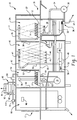
- Warewash machine 10 includes a housing 11 that can receive racks 12 of soiled wares 14 from an input side 16. The wares are moved through tunnel-like chambers from the input side toward a blower dryer unit 18 at an opposite exit end 17 of the warewash system by a suitable conveyor mechanism 20. Either continuously or intermittently moving conveyor mechanisms or combinations thereof may be used, depending, for example, on the style, model and size of the warewash system 10. Flight-type conveyors in which racks are not used are also possible.
- the racks 12 of soiled wares 14 enter the warewash system 10 through a flexible curtain 22 into a pre-wash chamber or zone 24 where sprays of liquid from upper and lower pre-wash manifolds 26 and 28 above and below the racks, respectively, function to flush heavier soil from the wares.
- the liquid for this purpose comes from a tank 30 and is delivered to the manifolds via a pump 32 and supply conduit 34.
- a drain structure 36 provides a single location where liquid is pumped from the tank 30 using the pump 32. Via the same drain structure, liquid can also be drained from the tank and out of the machine via drain path 37, for example, for a tank cleaning operation.
- the racks proceed to a next curtain 38 into a main wash chamber or zone 40, where the wares are subject to sprays of cleansing wash liquid (e.g., typically water with detergent) from upper and lower wash manifolds 42 and 44 with spray nozzles 47 and 49, respectively, these sprays being supplied through a supply conduit 46 by a pump 48, which draws from a main tank 50.
- a heater 58 such as an electrical immersion heater provided with suitable thermostatic controls (not shown), maintains the temperature of the cleansing liquid in the tank 50 at a suitable level.
- a device for adding a cleansing detergent to the liquid in tank 50 is During normal operation, pumps 32 and 48 are continuously driven, usually by separate motors, once the warewash system 10 is started for a period of time.
- the warewash system 10 may optionally include a power rinse (also known as post-wash) chamber or zone (not shown) that is substantially identical to main wash chamber 40.
- a power rinse also known as post-wash
- racks of wares proceed from the wash chamber 40 into the power rinse chamber, within which heated rinse water is sprayed onto the wares from upper and lower manifolds.
- the racks 12 of wares 14 exit the main wash chamber 40 through a curtain 52 into a final rinse chamber or zone 54.
- the final rinse chamber 54 is provided with upper and lower spray heads 56, 57 that are supplied with a flow of fresh hot water via pipe 62 running from a hot water booster 70 under the control of a variable speed pump 114 (or alternatively any other suitable valve capable of automatic control).
- a rack detector 64 may be actuated when a rack 12 of wares 14 is positioned in the final rinse chamber 54 and through suitable electrical controls (e.g., the controller mentioned below), the detector causes actuation of pump 114 which delivers incoming water and causes hot rinse water to move from the booster 70 to the spray heads 56, 57.
- the water then drains from the wares and is directed into the tank 50 by gravity flow.
- the rinsed rack 12 of wares 14 then exits the final rinse chamber 54 through curtain 66, moving into dryer unit 18, before exiting the outlet end 17 of the machine.
- An exhaust system 80 for pulling hot moist air from the machine may be provided.
- a cold water input 72 line may run through a waste heat recovery unit 82 (e.g., a fin-and-tube heat exchanger through which the incoming water flows, though other variations are possible) to recover heat from the exhaust air flowing across and/or through the unit 82.
- the water line or flow path 72 then runs through one or more condensers 84 (e.g., in the form of a plate heat exchanger or shell-and-tube heat exchangers, though other variations are possible), before delivering the water to the booster 70 for final heating.
- a condenser 88 may be located in the wash tank and a condenser 90 may be located in the blower dryer unit 18.
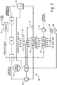
- a second waste heat recovery unit 92 may also be provided.
- the refrigerant medium circuit 100 includes an electronic thermal expansion valve 101, which leads to a waste heat recovery unit 92 to recover heat from warm waste air (e.g., the exhaust air flow) after some heat has already been removed from the exhaust air flow by unit 82.
- a compressor 102 compresses the refrigerant to produce superheated refrigerant, which then flows sequentially through the condensers 88, 90 and 84.
- condenser 88 may take the form of coil submerged in the wash tank 50 to deliver refrigerant heat to the wash water
- condenser 90 may take the form of a coil over which the drying air blows to deliver some refrigerant heat to the drying air
- condenser 84 which may be a plate-type heat exchanger, delivers residual refrigerant heat to the incoming fresh water.
- the incoming water to the booster heater passes through both the waste heat recovery unit 82 and condenser 84. In the event of undesired conditions within the machine, adjustments can be made to compensate.
- one or more sensors 110 are provided to monitor the conditions of the subcooled refrigerant.
- the monitoring may be continuous, periodic or triggered by some event (e.g., identification of a rack at a certain location in the machine).
- a temperature sensor and a pressure sensor may be used to monitor the subcooled refrigerant medium downstream of the last condenser 84 and upstream of the thermal expansion valve 101. If the monitoring indicates that the condition of the subcooled refrigerant medium has departed from a set specification, then corrective action can be take.
- any of the following conditions within the machine could lead to the condition of the subcooled refrigerant medium falling below a desired condition operating range, meaning the refrigerant medium has not been condensed sufficiently: an increase in the incoming cold water temperature, a decrease in the incoming cold water rate, an increase in the incoming cold water temperature and a decrease in the incoming cold water rate, an increase in waste moist hot air rate, an increase in waste moist hot air temperature, both increase in the waste moist hot air rate and waste moist hot air temperature, a decrease in the load on the warewash machine with an increase in the waste moist hot air rate and/or waste moist hot air temperature, or an inability of one of the condenser(s) to absorb or transfer the intended heat, as well as any combination of the above. All of these conditions will cause a decrease in the amount of condensation of the refrigerant medium that takes place in the refrigerant medium circuit 100 and could eventually cause the below range condition of the subcooled refrigerant medium.
- any or all of the following corrective actions could be initiated: controlling the compressor 102 to slow down while the electronic thermal expansion valve 101 automatically adjusts to maintain the necessary superheat to the compressor (e.g., based upon indications from a temperature sensor 115), decreasing the speed of exhaust fan 81 while monitoring air flow via meter 106 to maintain the necessary heat load across the waste heat recovery units 82 and 92 and to maintain the necessary superheat to the compressor 102, or increasing the speed of variable speed pump 114 that delivers the incoming cool fresh water. Any of these actions will increase the level of condensation that takes place and can be used to bring the condition of the subcooled refrigerant medium back up into the desired operating range.
- any of the following conditions within the machine could lead to the condition of the subcooled refrigerant medium falling above a desired condition operating range, meaning the refrigerant medium has been overly condensed or subcooled: a decrease in the incoming cold water temperature, an increase in the incoming cold water rate, both decrease in the incoming cold water temperature and increase of incoming cold water rate, a decrease in waste moist hot air rate, a decrease in waste moist hot air temperature, a decrease in both the waste moist hot air rate and waste moist hot air temperature, an increase in the load on the warewash machine with a decrease in the waste moist hot air rate and/or waste moist hot air temperature. All of these conditions will cause an increase in the amount of condensation of the refrigerant medium that takes place in the refrigerant medium circuit 100 and could eventually cause the above range condition of the subcooled refrigerant medium.
- any or all of the following corrective actions can be initiated: controlling the compressor 102 to speed up while the electronic thermal expansion valve 101 adjusts to maintain the necessary superheat to the compressor, or increasing the speed of the exhaust fan 81 to maintain the necessary heat load across the waste heat recovery units 82 and 92 in order to maintain the necessary superheat to the compressor 102, or decreasing the speed of the variable speed pump 114 that delivers the incoming cool fresh water. Any of these actions will decrease the level of condensation that takes place and can be used to bring the condition of the subcooled refrigerant medium back down into the desired operating range.
- the speed of both the compressor 102 and exhaust fan 81 may be decreased, relying upon the excess heat load to maintain the minimum heat required in the machine and also to prevent unnecessary steam escape from the loading and unloading ends of the machine.
- the speed of the exhaust fan 81 may be decreased to conserve heat in the machine.
- the exhaust fan 81 is typically on when the compressor 102 is on to prevent low pressure, unless conditions are close to high pressure, in which case the fan 81 may be shutdown.
- the moist hot air temperature (as indicated by temperature sensor 108) and flowrate (as indicated by sensor 106) may be used to determine the fan speed to maintain a desired set temperature drop across the waste heat recovery units 82 and 92, thereby maintaining the needed superheat and exhaust conditions.
- the subcooled condition of the refrigerant medium may be a difference between the actual temperature indicated by the temperature sensor 110 less a condenser saturation temperature corresponding to the pressure indicated by pressure sensor 110.
- An exemplary acceptable subcooled condition operating range may be between 10°F and 15°F, though variations are possible. Above 15°F indicates the refrigerant medium has been overly condensed or subcooled, and below 10°F indicates that the refrigerant medium has not been condensed enough (e.g., gas may be present).
- the condenser saturation temperature may be determined by reading the pressure indicated by pressure sensor 110 and (i) using a refrigerant pressure/temperature chart or table (e.g., stored in controller memory) to convert the pressure reading to the condenser saturation temperature or (ii) using an equation fitted to a refrigerant medium pressure/temperature chart to convert the pressure reading to the condenser saturation temperature.
- a refrigerant pressure/temperature chart or table e.g., stored in controller memory
- a controller 150 may be provided to effect initiation and control of any of the corrective actions mentioned above based upon indications from the temperature sensor and pressure sensor, as well as for controlling other functions and operations of the machine as discussed above.
- the term controller is intended to broadly encompass any circuit (e.g., solid state, application specific integrated circuit (ASIC), an electronic circuit, a combinational logic circuit, a field programmable gate array (FPGA)), processor (e.g., shared, dedicated, or group - including hardware or software that executes code) or other component, or a combination of some or all of the above, that carries out the control functions of the machine or the control functions of any component thereof.
- the controller may include variable adjustment functionality that enables, for example, the acceptable subcooled condition operating range to be varied (e.g., via an operator interface associated with the controller 150 or via a restricted service/maintenance personnel interface).
- Ensuring that the refrigerant medium remains in a desired operating range as indicated above can help system operation by (i) assuring that the refrigerant medium is fully condensed to assist efficient operation of the thermal expansion valve 101, and/or (ii) reducing or eliminating the presence of gas in the refrigerant medium at the upstream side of the thermal expansion valve as the presence of such gas will tend to restrict refrigerant medium flow hence starving the evaporator of refrigerant medium, and/or (ii) assuring that the refrigerant medium is not overcooled coming out of the condenser chain, as such overcooling will require more energy delivery to the refrigerant medium at the evaporator in order to raise the refrigerant medium to desired compressor suction conditions, and if the evaporator is unable to deliver sufficient energy the performance and/or life of the compressor may be adversely impacted.
- the above machine provides an advantageous method of correcting undesired conditions of a refrigerant medium circuit in a warewash machine.
- the method involves: identifying an under-condensed condition of subcooled refrigerant medium in the refrigerant medium circuit or an over-condensed condition of subcooled refrigerant medium in the refrigeration medium circuit; and in response to identification of the under-condensed or over-condensed condition, varying at least one of (i) a speed of a compressor of the refrigerant medium circuit, (ii) a speed of an exhaust fan that causes air flow across the waste heat recovery unit or (iii) a speed of a pump that controls incoming water flow through the waste heat recovery unit and the condenser.
- the identifying step includes sensing a refrigerant medium temperature and a refrigerant medium pressure downstream of all condensers in the refrigerant medium circuit. In one example of such an implementation, the identifying step includes determining a difference between the sensed refrigerant medium temperature less a condenser saturation temperature corresponding to the sensed refrigerant medium pressure. If the under-condensed condition of subcooled refrigerant medium is identified, the varying step involves at least one of: (i) reducing the speed of the compressor, (ii) reducing the speed of the exhaust fan or (iii) increasing the speed of the pump.
- the varying step involves at least one of: (i) increasing the speed of the compressor, (ii) increasing the speed of the exhaust fan or (iii) decreasing the speed of the pump.
- the method may also involve monitoring temperature and flow rate of exhaust air and responsively adjusting the speed of the exhaust fan to maintain a set temperature drop across the waste heat recovery unit.
- refrigerant commonly refers to known acceptable refrigerants, but other thermal fluids could be used in refrigerant type circuits.
- refrigerant medium is intended to encompass all such traditional refrigerants and other thermal fluids. Embodiments with varying numbers of waste heat recovery units and/or numbers of condensers are also contemplated.
Landscapes
- Engineering & Computer Science (AREA)
- Water Supply & Treatment (AREA)
- Physics & Mathematics (AREA)
- Mechanical Engineering (AREA)
- Thermal Sciences (AREA)
- General Engineering & Computer Science (AREA)
- Drying Of Solid Materials (AREA)
- Air Conditioning Control Device (AREA)
Claims (13)
- Geschirrspülmaschine (10) zum Spülen von Geschirr (14), die Folgendes umfasst:einen Raum zum Aufnehmen von Geschirr (14), wobei der Raum mindestens eine Spülzone (40) aufweist;eine Abwärmerückgewinnungseinheit (82), die angeordnet ist, Wärme aus der Abluft der Maschine (10) auf einströmendes Wasser, das sich entlang eines Wasserströmungswegs durch die Abwärmerückgewinnungseinheit (82) bewegt, an eine Zusatzheizung (70) der Maschine (10) zu übertragen;einen Kühlmittelkreislauf (100), der mindestens einen ersten Kondensator (84) aufweist, der angeordnet ist, dem einströmenden Wasser Kühlmittelwärme zuzuführen;gekennzeichnet durcheine Steuerungsanordnung zum Überwachen einer Unterkühlungsbedingung des Kühlmittels und zum darauf ansprechenden Modifizieren des Betriebs von einem oder mehreren aus Folgenden: (i) einer Drehzahl eines Kompressors (102) des Kühlmittelkreislaufs (100), (ii) einer Drehzahl eines Abluftgebläses (81), das einen Luftstrom über die Abwärmerückgewinnungseinheit (82) verursacht, oder (iii) einer Drehzahl einer Pumpe (114), die den einströmenden Wasserstrom entlang des Wasserströmungswegs steuert.
- Maschine (10) nach Anspruch 1,
wobei die Steuerungsanordnung einen Kühlmitteltemperatursensor (108, 110, 115) und einen Kühlmitteldrucksensor (110) stromabwärts von allen Kondensatoren (84, 88, 90) in dem Kühlmittelkreislauf (100) beinhaltet. - Maschine (10) nach Anspruch 2,
wobei die Steuerungsanordnung eine Steuerung (150) beinhaltet, die mit dem Kühlmitteltemperatursensor (108, 110, 115) und dem Kühlmitteldrucksensor (110) verbunden ist, wobei die Steuerung (150) konfiguriert ist zum Bestimmen einer Unterkühlungsbedingung des Kühlmittels und zum darauf ansprechenden Steuern von mindestens einem aus Folgenden: (i) der Drehzahl des Kompressors (102), (ii) der Drehzahl des Abluftgebläses (81) oder (iii) der Drehzahl der Pumpe (114). - Maschine (10) nach Anspruch 3,
wobei die Unterkühlungsbedingung des Kühlmittels eine Differenz zwischen einer tatsächlichen Temperatur, die von dem Kühlmitteltemperatursensor (108, 110, 115) angegeben wird, und einer Kondensatorsättigungstemperatur, die einem Druck entspricht, der von dem Kühlmitteldrucksensor (110) angegeben wird, ist. - Maschine (10) nach Anspruch 4,
wobei die Steuerung (150) konfiguriert ist zum Identifizieren einer vordefinierten Unterkühlungsbedingung, die eine Unterverdichtung des Kühlmittels anzeigt, und zum darauf ansprechenden Bewirken von mindestens einem aus Folgenden: (i) einer Reduktion der Drehzahl des Kompressors (102), (ii) einer Reduktion der Drehzahl des Abluftgebläses (81) oder (iii) einer Zunahme der Drehzahl der Pumpe (114). - Maschine (10) nach Anspruch 4,
wobei die Steuerung (150) konfiguriert ist zum Identifizieren einer vordefinierten Unterkühlungsbedingung, die eine Überverdichtung des Kühlmittels anzeigt und zum darauf ansprechenden Bewirken von mindestens einem aus: (i) einer Zunahme der Drehzahl des Kompressors (102), (ii) einer Zunahme der Drehzahl des Abluftgebläses (81) oder (iii) einer Abnahme der Drehzahl der Pumpe (114). - Maschine (10) nach einem der vorhergehenden Ansprüche,
wobei die Steuerungsanordnung ferner konfiguriert ist zum Überwachen der Temperatur und der Strömungsrate der Abluft und zum darauf ansprechenden Anpassen der Drehzahl des Abluftgebläses, um einen eingestellten Temperaturabfall über die Abwärmerückgewinnungseinheit (82) aufrecht zu erhalten. - Verfahren zum adaptiven Steuern einer Geschirrspülmaschine (10), die Folgendes beinhaltet:einen Raum zum Aufnehmen von Geschirr (14), wobei der Raum mindestens eine Spülzone (40) aufweist, einen Kühlmittelkreislauf (100), der mindestens einen Kondensator (84) beinhaltet, durch welchen einströmendes Wasser zur Maschine (10) strömt, und eine Abwärmerückgewinnungseinheit (82), durch welche einströmendes Wasser zur Maschine (10) strömt,gekennzeichnet durchIdentifizieren einer Unterverdichtungsbedingung von unterkühltem Kühlmittel in dem Kühlmittelkreislauf (100) oder einer Überverdichtungsbedingung von unterkühltem Kühlmittel im Kühlmittelkreislauf (100);
undin Reaktion auf die Identifikation der Unterverdichtungs- oder Überverdichtungsbedingung, Variieren von mindestens einem aus Folgenden (i) einer Drehzahl eines Kompressors (102) des Kühlmittelkreislaufs (100), (ii) einer Drehzahl eines Abluftgebläses (81), das einen Luftstrom über die Abwärmerückgewinnungseinheit (82) verursacht, oder (iii) einer Drehzahl einer Pumpe (114), die einen einströmenden Wasserstrom durch die Abwärmerückgewinnungseinheit (82) und den Kondensator (84) steuert. - Verfahren nach Anspruch 8,
wobei der Identifizierungsschritt Erfassen einer Kühlmitteltemperatur und eines Kühlmitteldrucks stromabwärts von allen Kondensatoren (84, 88, 90) in dem Kühlmittelkreislauf (100) beinhaltet. - Verfahren nach Anspruch 9,
wobei der Identifizierungsschritt Bestimmen einer Differenz zwischen der erfassten Kühlmitteltemperatur und einer Kondensatorsättigungstemperatur, die dem erfassten Kühlmitteldruck entspricht, beinhaltet. - Verfahren nach Anspruch 10,
wobei, wenn die Unterverdichtungsbedingung von unterkühltem Kühlmittel identifiziert wird, der Variierungsschritt mindestens eins aus Folgenden beinhaltet: (i) Reduzieren der Drehzahl des Kompressors (102), (ii) Reduzieren der Drehzahl des Abluftgebläses (81) oder (iii) Erhöhen der Drehzahl der Pumpe (114). - Verfahren nach Anspruch 10,
wobei, wenn die Überverdichtungsbedingung von unterkühltem Kühlmittel identifiziert wird, der Variierungsschritt mindestens eins aus Folgenden beinhaltet: (i) Erhöhen der Drehzahl des Kompressors (102), (ii) Erhöhen der Drehzahl des Abluftgebläses (81) oder (iii) Verringern der Drehzahl der Pumpe (114). - Verfahren nach einem der Ansprüche 8 bis 12, das ferner beinhaltet:
Überwachen der Temperatur und der Strömungsrate der Abluft und darauf ansprechendes Anpassen der Drehzahl des Abluftgebläses (81), um einen eingestellten Temperaturabfall über die Abwärmerückgewinnungseinheit (82) aufrecht zu erhalten.
Applications Claiming Priority (3)
| Application Number | Priority Date | Filing Date | Title |
|---|---|---|---|
| US201562199367P | 2015-07-31 | 2015-07-31 | |
| US15/178,596 US20170027409A1 (en) | 2015-07-31 | 2016-06-10 | Warewasher with heat recovery system |
| PCT/US2016/043071 WO2017023549A1 (en) | 2015-07-31 | 2016-07-20 | Warewasher with heat recovery system |
Publications (2)
| Publication Number | Publication Date |
|---|---|
| EP3328259A1 EP3328259A1 (de) | 2018-06-06 |
| EP3328259B1 true EP3328259B1 (de) | 2020-02-05 |
Family
ID=57886672
Family Applications (1)
| Application Number | Title | Priority Date | Filing Date |
|---|---|---|---|
| EP16745327.3A Active EP3328259B1 (de) | 2015-07-31 | 2016-07-20 | Geschirrspülmaschine mit wärmerückgewinnungssystem |
Country Status (4)
| Country | Link |
|---|---|
| US (1) | US20170027409A1 (de) |
| EP (1) | EP3328259B1 (de) |
| CN (1) | CN108135428B (de) |
| WO (1) | WO2017023549A1 (de) |
Families Citing this family (8)
| Publication number | Priority date | Publication date | Assignee | Title |
|---|---|---|---|---|
| KR101778172B1 (ko) * | 2016-11-15 | 2017-09-26 | 주식회사프라임 | 식기 세척기 |
| US20210015339A1 (en) * | 2018-03-29 | 2021-01-21 | Illinois Tool Works Inc. | Warewash machine with submersible cutlery basket |
| ES2727308A1 (es) * | 2018-04-12 | 2019-10-15 | Bsh Electrodomesticos Espana Sa | Máquina lavavajillas doméstica con condensador variable en una disposición de bomba de calor. |
| ES2727310A1 (es) * | 2018-04-12 | 2019-10-15 | Bsh Electrodomesticos Espana Sa | Máquina lavavajillas doméstica con un evaporador variable en su disposición de bomba de calor. |
| CN112437628A (zh) * | 2018-04-24 | 2021-03-02 | 伊利诺斯工具制品有限公司 | 热器皿的能量回收 |
| EP3901531A4 (de) * | 2018-12-18 | 2021-12-29 | Mitsubishi Electric Corporation | Klimatisierungsvorrichtung |
| DE102023100906A1 (de) * | 2023-01-16 | 2024-07-18 | Illinois Tool Works Inc. | Spülmaschine mit wärmerückgewinnungsvorrichtung |
| DE102023130573A1 (de) * | 2023-11-06 | 2025-05-08 | Winterhalter Product & Technology GmbH | Geschirrspülmaschine mit wärmepumpenvorrichtung und ansaugvorrichtung für maschinenluft und umgebungsluft |
Family Cites Families (7)
| Publication number | Priority date | Publication date | Assignee | Title |
|---|---|---|---|---|
| US4553401A (en) * | 1982-03-05 | 1985-11-19 | Fisher Ralph H | Reversible cycle heating and cooling system |
| JP3971364B2 (ja) * | 2002-11-01 | 2007-09-05 | 三星電子株式会社 | 食器洗い機 |
| JP2004154565A (ja) * | 2002-11-01 | 2004-06-03 | Samsung Electronics Co Ltd | 温風発生器を備えた食器洗い機 |
| WO2008106774A1 (en) * | 2007-03-02 | 2008-09-12 | Victor Juchymenko | Controlled organic rankine cycle system for recovery and conversion of thermal energy |
| CN101581294B (zh) * | 2009-06-12 | 2011-03-30 | 南京师范大学 | 一种冷凝热量回收型制冷压缩机性能试验系统 |
| DE102013224440A1 (de) * | 2013-11-28 | 2015-05-28 | Illinois Tool Works Inc. | Transportspülmaschine, insbesondere gewerbliche Transportspülmaschine |
| PL3148392T3 (pl) * | 2014-06-02 | 2018-08-31 | Electrolux Appliances Aktiebolag | Urządzenie gospodarstwa domowego |
-
2016
- 2016-06-10 US US15/178,596 patent/US20170027409A1/en not_active Abandoned
- 2016-07-20 WO PCT/US2016/043071 patent/WO2017023549A1/en not_active Ceased
- 2016-07-20 EP EP16745327.3A patent/EP3328259B1/de active Active
- 2016-07-20 CN CN201680044115.8A patent/CN108135428B/zh active Active
Non-Patent Citations (1)
| Title |
|---|
| None * |
Also Published As
| Publication number | Publication date |
|---|---|
| WO2017023549A1 (en) | 2017-02-09 |
| US20170027409A1 (en) | 2017-02-02 |
| CN108135428A (zh) | 2018-06-08 |
| CN108135428B (zh) | 2021-11-05 |
| EP3328259A1 (de) | 2018-06-06 |
Similar Documents
| Publication | Publication Date | Title |
|---|---|---|
| EP3328259B1 (de) | Geschirrspülmaschine mit wärmerückgewinnungssystem | |
| US10722099B2 (en) | Warewasher with heat recovery system | |
| US10722097B2 (en) | Warewasher with heat recovery system | |
| EP3328258B1 (de) | Geschirrspülmaschine mit wärmerückgewinnungssystem | |
| CN108697296B (zh) | 器皿清洗机器干燥系统和方法 | |
| US10921046B2 (en) | Method for defrosting an evaporator of a sealed system | |
| US11369247B2 (en) | Ware washing machine with heat pump and modulating valve | |
| US11751747B2 (en) | Warewash machine energy conservation incorporating vent controls | |
| US20210361140A1 (en) | Energy recovery from hot wares | |
| CN115868815B (zh) | 液体处理装置及其控制方法、控制装置和可读存储介质 | |
| EP3878341A1 (de) | Spülmaschine mit leerlaufsystem |
Legal Events
| Date | Code | Title | Description |
|---|---|---|---|
| STAA | Information on the status of an ep patent application or granted ep patent |
Free format text: STATUS: THE INTERNATIONAL PUBLICATION HAS BEEN MADE |
|
| PUAI | Public reference made under article 153(3) epc to a published international application that has entered the european phase |
Free format text: ORIGINAL CODE: 0009012 |
|
| STAA | Information on the status of an ep patent application or granted ep patent |
Free format text: STATUS: REQUEST FOR EXAMINATION WAS MADE |
|
| 17P | Request for examination filed |
Effective date: 20180116 |
|
| AK | Designated contracting states |
Kind code of ref document: A1 Designated state(s): AL AT BE BG CH CY CZ DE DK EE ES FI FR GB GR HR HU IE IS IT LI LT LU LV MC MK MT NL NO PL PT RO RS SE SI SK SM TR |
|
| AX | Request for extension of the european patent |
Extension state: BA ME |
|
| DAV | Request for validation of the european patent (deleted) | ||
| DAX | Request for extension of the european patent (deleted) | ||
| GRAP | Despatch of communication of intention to grant a patent |
Free format text: ORIGINAL CODE: EPIDOSNIGR1 |
|
| STAA | Information on the status of an ep patent application or granted ep patent |
Free format text: STATUS: GRANT OF PATENT IS INTENDED |
|
| INTG | Intention to grant announced |
Effective date: 20190725 |
|
| GRAS | Grant fee paid |
Free format text: ORIGINAL CODE: EPIDOSNIGR3 |
|
| GRAJ | Information related to disapproval of communication of intention to grant by the applicant or resumption of examination proceedings by the epo deleted |
Free format text: ORIGINAL CODE: EPIDOSDIGR1 |
|
| GRAL | Information related to payment of fee for publishing/printing deleted |
Free format text: ORIGINAL CODE: EPIDOSDIGR3 |
|
| STAA | Information on the status of an ep patent application or granted ep patent |
Free format text: STATUS: REQUEST FOR EXAMINATION WAS MADE |
|
| GRAJ | Information related to disapproval of communication of intention to grant by the applicant or resumption of examination proceedings by the epo deleted |
Free format text: ORIGINAL CODE: EPIDOSDIGR1 |
|
| GRAR | Information related to intention to grant a patent recorded |
Free format text: ORIGINAL CODE: EPIDOSNIGR71 |
|
| STAA | Information on the status of an ep patent application or granted ep patent |
Free format text: STATUS: GRANT OF PATENT IS INTENDED |
|
| INTC | Intention to grant announced (deleted) | ||
| GRAA | (expected) grant |
Free format text: ORIGINAL CODE: 0009210 |
|
| STAA | Information on the status of an ep patent application or granted ep patent |
Free format text: STATUS: THE PATENT HAS BEEN GRANTED |
|
| INTG | Intention to grant announced |
Effective date: 20191218 |
|
| AK | Designated contracting states |
Kind code of ref document: B1 Designated state(s): AL AT BE BG CH CY CZ DE DK EE ES FI FR GB GR HR HU IE IS IT LI LT LU LV MC MK MT NL NO PL PT RO RS SE SI SK SM TR |
|
| REG | Reference to a national code |
Ref country code: GB Ref legal event code: FG4D |
|
| REG | Reference to a national code |
Ref country code: AT Ref legal event code: REF Ref document number: 1229364 Country of ref document: AT Kind code of ref document: T Effective date: 20200215 |
|
| REG | Reference to a national code |
Ref country code: DE Ref legal event code: R096 Ref document number: 602016029125 Country of ref document: DE |
|
| REG | Reference to a national code |
Ref country code: IE Ref legal event code: FG4D |
|
| REG | Reference to a national code |
Ref country code: CH Ref legal event code: EP |
|
| REG | Reference to a national code |
Ref country code: NL Ref legal event code: MP Effective date: 20200205 |
|
| PG25 | Lapsed in a contracting state [announced via postgrant information from national office to epo] |
Ref country code: PT Free format text: LAPSE BECAUSE OF FAILURE TO SUBMIT A TRANSLATION OF THE DESCRIPTION OR TO PAY THE FEE WITHIN THE PRESCRIBED TIME-LIMIT Effective date: 20200628 Ref country code: RS Free format text: LAPSE BECAUSE OF FAILURE TO SUBMIT A TRANSLATION OF THE DESCRIPTION OR TO PAY THE FEE WITHIN THE PRESCRIBED TIME-LIMIT Effective date: 20200205 Ref country code: FI Free format text: LAPSE BECAUSE OF FAILURE TO SUBMIT A TRANSLATION OF THE DESCRIPTION OR TO PAY THE FEE WITHIN THE PRESCRIBED TIME-LIMIT Effective date: 20200205 Ref country code: NO Free format text: LAPSE BECAUSE OF FAILURE TO SUBMIT A TRANSLATION OF THE DESCRIPTION OR TO PAY THE FEE WITHIN THE PRESCRIBED TIME-LIMIT Effective date: 20200505 |
|
| REG | Reference to a national code |
Ref country code: LT Ref legal event code: MG4D |
|
| PG25 | Lapsed in a contracting state [announced via postgrant information from national office to epo] |
Ref country code: BG Free format text: LAPSE BECAUSE OF FAILURE TO SUBMIT A TRANSLATION OF THE DESCRIPTION OR TO PAY THE FEE WITHIN THE PRESCRIBED TIME-LIMIT Effective date: 20200505 Ref country code: HR Free format text: LAPSE BECAUSE OF FAILURE TO SUBMIT A TRANSLATION OF THE DESCRIPTION OR TO PAY THE FEE WITHIN THE PRESCRIBED TIME-LIMIT Effective date: 20200205 Ref country code: GR Free format text: LAPSE BECAUSE OF FAILURE TO SUBMIT A TRANSLATION OF THE DESCRIPTION OR TO PAY THE FEE WITHIN THE PRESCRIBED TIME-LIMIT Effective date: 20200506 Ref country code: LV Free format text: LAPSE BECAUSE OF FAILURE TO SUBMIT A TRANSLATION OF THE DESCRIPTION OR TO PAY THE FEE WITHIN THE PRESCRIBED TIME-LIMIT Effective date: 20200205 Ref country code: SE Free format text: LAPSE BECAUSE OF FAILURE TO SUBMIT A TRANSLATION OF THE DESCRIPTION OR TO PAY THE FEE WITHIN THE PRESCRIBED TIME-LIMIT Effective date: 20200205 Ref country code: IS Free format text: LAPSE BECAUSE OF FAILURE TO SUBMIT A TRANSLATION OF THE DESCRIPTION OR TO PAY THE FEE WITHIN THE PRESCRIBED TIME-LIMIT Effective date: 20200605 |
|
| PG25 | Lapsed in a contracting state [announced via postgrant information from national office to epo] |
Ref country code: NL Free format text: LAPSE BECAUSE OF FAILURE TO SUBMIT A TRANSLATION OF THE DESCRIPTION OR TO PAY THE FEE WITHIN THE PRESCRIBED TIME-LIMIT Effective date: 20200205 |
|
| PG25 | Lapsed in a contracting state [announced via postgrant information from national office to epo] |
Ref country code: ES Free format text: LAPSE BECAUSE OF FAILURE TO SUBMIT A TRANSLATION OF THE DESCRIPTION OR TO PAY THE FEE WITHIN THE PRESCRIBED TIME-LIMIT Effective date: 20200205 Ref country code: EE Free format text: LAPSE BECAUSE OF FAILURE TO SUBMIT A TRANSLATION OF THE DESCRIPTION OR TO PAY THE FEE WITHIN THE PRESCRIBED TIME-LIMIT Effective date: 20200205 Ref country code: DK Free format text: LAPSE BECAUSE OF FAILURE TO SUBMIT A TRANSLATION OF THE DESCRIPTION OR TO PAY THE FEE WITHIN THE PRESCRIBED TIME-LIMIT Effective date: 20200205 Ref country code: SM Free format text: LAPSE BECAUSE OF FAILURE TO SUBMIT A TRANSLATION OF THE DESCRIPTION OR TO PAY THE FEE WITHIN THE PRESCRIBED TIME-LIMIT Effective date: 20200205 Ref country code: SK Free format text: LAPSE BECAUSE OF FAILURE TO SUBMIT A TRANSLATION OF THE DESCRIPTION OR TO PAY THE FEE WITHIN THE PRESCRIBED TIME-LIMIT Effective date: 20200205 Ref country code: CZ Free format text: LAPSE BECAUSE OF FAILURE TO SUBMIT A TRANSLATION OF THE DESCRIPTION OR TO PAY THE FEE WITHIN THE PRESCRIBED TIME-LIMIT Effective date: 20200205 Ref country code: RO Free format text: LAPSE BECAUSE OF FAILURE TO SUBMIT A TRANSLATION OF THE DESCRIPTION OR TO PAY THE FEE WITHIN THE PRESCRIBED TIME-LIMIT Effective date: 20200205 Ref country code: LT Free format text: LAPSE BECAUSE OF FAILURE TO SUBMIT A TRANSLATION OF THE DESCRIPTION OR TO PAY THE FEE WITHIN THE PRESCRIBED TIME-LIMIT Effective date: 20200205 |
|
| REG | Reference to a national code |
Ref country code: DE Ref legal event code: R097 Ref document number: 602016029125 Country of ref document: DE |
|
| REG | Reference to a national code |
Ref country code: AT Ref legal event code: MK05 Ref document number: 1229364 Country of ref document: AT Kind code of ref document: T Effective date: 20200205 |
|
| PLBE | No opposition filed within time limit |
Free format text: ORIGINAL CODE: 0009261 |
|
| STAA | Information on the status of an ep patent application or granted ep patent |
Free format text: STATUS: NO OPPOSITION FILED WITHIN TIME LIMIT |
|
| 26N | No opposition filed |
Effective date: 20201106 |
|
| PG25 | Lapsed in a contracting state [announced via postgrant information from national office to epo] |
Ref country code: IT Free format text: LAPSE BECAUSE OF FAILURE TO SUBMIT A TRANSLATION OF THE DESCRIPTION OR TO PAY THE FEE WITHIN THE PRESCRIBED TIME-LIMIT Effective date: 20200205 Ref country code: AT Free format text: LAPSE BECAUSE OF FAILURE TO SUBMIT A TRANSLATION OF THE DESCRIPTION OR TO PAY THE FEE WITHIN THE PRESCRIBED TIME-LIMIT Effective date: 20200205 |
|
| PG25 | Lapsed in a contracting state [announced via postgrant information from national office to epo] |
Ref country code: PL Free format text: LAPSE BECAUSE OF FAILURE TO SUBMIT A TRANSLATION OF THE DESCRIPTION OR TO PAY THE FEE WITHIN THE PRESCRIBED TIME-LIMIT Effective date: 20200205 Ref country code: MC Free format text: LAPSE BECAUSE OF FAILURE TO SUBMIT A TRANSLATION OF THE DESCRIPTION OR TO PAY THE FEE WITHIN THE PRESCRIBED TIME-LIMIT Effective date: 20200205 Ref country code: SI Free format text: LAPSE BECAUSE OF FAILURE TO SUBMIT A TRANSLATION OF THE DESCRIPTION OR TO PAY THE FEE WITHIN THE PRESCRIBED TIME-LIMIT Effective date: 20200205 |
|
| REG | Reference to a national code |
Ref country code: CH Ref legal event code: PL |
|
| GBPC | Gb: european patent ceased through non-payment of renewal fee |
Effective date: 20200720 |
|
| REG | Reference to a national code |
Ref country code: BE Ref legal event code: MM Effective date: 20200731 |
|
| PG25 | Lapsed in a contracting state [announced via postgrant information from national office to epo] |
Ref country code: LI Free format text: LAPSE BECAUSE OF NON-PAYMENT OF DUE FEES Effective date: 20200731 Ref country code: LU Free format text: LAPSE BECAUSE OF NON-PAYMENT OF DUE FEES Effective date: 20200720 Ref country code: CH Free format text: LAPSE BECAUSE OF NON-PAYMENT OF DUE FEES Effective date: 20200731 Ref country code: FR Free format text: LAPSE BECAUSE OF NON-PAYMENT OF DUE FEES Effective date: 20200731 Ref country code: GB Free format text: LAPSE BECAUSE OF NON-PAYMENT OF DUE FEES Effective date: 20200720 |
|
| PG25 | Lapsed in a contracting state [announced via postgrant information from national office to epo] |
Ref country code: BE Free format text: LAPSE BECAUSE OF NON-PAYMENT OF DUE FEES Effective date: 20200731 |
|
| PG25 | Lapsed in a contracting state [announced via postgrant information from national office to epo] |
Ref country code: IE Free format text: LAPSE BECAUSE OF NON-PAYMENT OF DUE FEES Effective date: 20200720 |
|
| PG25 | Lapsed in a contracting state [announced via postgrant information from national office to epo] |
Ref country code: TR Free format text: LAPSE BECAUSE OF FAILURE TO SUBMIT A TRANSLATION OF THE DESCRIPTION OR TO PAY THE FEE WITHIN THE PRESCRIBED TIME-LIMIT Effective date: 20200205 Ref country code: MT Free format text: LAPSE BECAUSE OF FAILURE TO SUBMIT A TRANSLATION OF THE DESCRIPTION OR TO PAY THE FEE WITHIN THE PRESCRIBED TIME-LIMIT Effective date: 20200205 Ref country code: CY Free format text: LAPSE BECAUSE OF FAILURE TO SUBMIT A TRANSLATION OF THE DESCRIPTION OR TO PAY THE FEE WITHIN THE PRESCRIBED TIME-LIMIT Effective date: 20200205 |
|
| PG25 | Lapsed in a contracting state [announced via postgrant information from national office to epo] |
Ref country code: MK Free format text: LAPSE BECAUSE OF FAILURE TO SUBMIT A TRANSLATION OF THE DESCRIPTION OR TO PAY THE FEE WITHIN THE PRESCRIBED TIME-LIMIT Effective date: 20200205 Ref country code: AL Free format text: LAPSE BECAUSE OF FAILURE TO SUBMIT A TRANSLATION OF THE DESCRIPTION OR TO PAY THE FEE WITHIN THE PRESCRIBED TIME-LIMIT Effective date: 20200205 |
|
| P01 | Opt-out of the competence of the unified patent court (upc) registered |
Effective date: 20230606 |
|
| PGFP | Annual fee paid to national office [announced via postgrant information from national office to epo] |
Ref country code: DE Payment date: 20250729 Year of fee payment: 10 |