EP3327905A1 - Electric machine for a motor vehicle - Google Patents
Electric machine for a motor vehicle Download PDFInfo
- Publication number
- EP3327905A1 EP3327905A1 EP17203499.3A EP17203499A EP3327905A1 EP 3327905 A1 EP3327905 A1 EP 3327905A1 EP 17203499 A EP17203499 A EP 17203499A EP 3327905 A1 EP3327905 A1 EP 3327905A1
- Authority
- EP
- European Patent Office
- Prior art keywords
- annular
- piece
- cover
- face
- electric machine
- Prior art date
- Legal status (The legal status is an assumption and is not a legal conclusion. Google has not performed a legal analysis and makes no representation as to the accuracy of the status listed.)
- Withdrawn
Links
Images


Classifications
-
- H—ELECTRICITY
- H02—GENERATION; CONVERSION OR DISTRIBUTION OF ELECTRIC POWER
- H02K—DYNAMO-ELECTRIC MACHINES
- H02K5/00—Casings; Enclosures; Supports
- H02K5/24—Casings; Enclosures; Supports specially adapted for suppression or reduction of noise or vibrations
-
- H—ELECTRICITY
- H02—GENERATION; CONVERSION OR DISTRIBUTION OF ELECTRIC POWER
- H02K—DYNAMO-ELECTRIC MACHINES
- H02K5/00—Casings; Enclosures; Supports
- H02K5/04—Casings or enclosures characterised by the shape, form or construction thereof
- H02K5/20—Casings or enclosures characterised by the shape, form or construction thereof with channels or ducts for flow of cooling medium
- H02K5/203—Casings or enclosures characterised by the shape, form or construction thereof with channels or ducts for flow of cooling medium specially adapted for liquids, e.g. cooling jackets
Definitions
- the present invention relates to a housing of an electric machine as well as an electric machine and a motor equipped with such a housing.
- turbocharger In the case where the torque setpoint of a combustion engine varies suddenly and where the engine boost to help him follow the torque setpoint, is only obtained through a turbocharger, the response time of the latter, still called “turbolag", is a problem.
- various solutions are known, for example the use of several selectively active turbochargers, an electric compressor or a centrifugal mechanical compressor.
- An electric supercharger is conventionally implemented in the air intake line of a combustion engine of a motor vehicle, upstream or downstream of a turbocharger.
- the figure 1 represents an electric motor 10 for powering the compressor.
- the electric motor 10 comprises a guided rotor 12 rotated in an annular stator 14 of the electric motor 10.
- the annular stator 14 is mounted in a housing 16 of an annular housing 18 which comprises in its thickness an annular cavity 20 in which a coolant of the electric machine in operation.
- the compressor comprises a cover 22 resting on the casing 18 and providing rotational guidance of the rotor 12.
- the cover 22 comprises a central orifice 24 for the shaft passage of the rotor 12 and its connection to a compressor wheel as is well known to those skilled in the art.
- the electric motor provides the power necessary for the rotation of the compression wheel thus allowing the temporary increase of the compression efficiency.
- this assembly is a source of noise pollution in the motor vehicle. Indeed, the electromagnetic forces applied to the rotor and the stator in operation lead to microdetrations of the rotor and the stator relative to each other at high audible frequencies, typically between 1000 and 20000Hz. These vibrations, which are transmitted by the stator to the casing integral with the structural frame of the motor vehicle, induce an increase in audible background noise in the immediate environment of the vehicle. Unlike other sources of noise, this type of sound source is intrinsic to the operation of the electric motor and it is difficult to eliminate.
- the invention proposes to provide an effective, simple and economical solution to the aforementioned problems.
- a support assembly for an electrical machine comprising a housing having a housing, of longitudinal axis, inside which is intended to be mounted the stator of the electric machine and a closure cover of an opening of the housing intended to be traversed by the rotor of the electric machine, characterized in that the casing comprises a first annular piece intended to support radially internally the stator of the electric machine and a second part supporting the first part, the first annular piece being connected to the second piece and to the lid by means of elastically deformable means.
- the stator of the electric machine is connected to the housing and to the cover by intermediate means which are elastically deformable, thereby avoiding the transmission of high frequency vibrations from the stator to the housing. Therefore, the noise pollution is reduced, which improves the acoustic comfort inside a passenger compartment of a motor vehicle.
- the elastically deformable means comprise annular seals interposed between a first longitudinal end of the first annular piece and the second piece and between the cover and a second longitudinal end of the first annular piece opposite the first end.
- one of the first annular piece and the second piece may comprise an annular centering and bearing face of the first piece on the second piece, this annular face being slanted obliquely by relative to the longitudinal axis and an annular seal being applied thereto and held in an annular recess of an annular L-shaped portion of the other of the first annular piece and the second piece.
- This type of configuration makes it possible to absorb the vibrations while achieving, in a simple way, the centering of the first part of the casing on the second part of the casing by means of obliquely inclined faces.
- one of the first annular part and the cover may comprise an annular centering and bearing face of the cover on the first part, this face being inclined obliquely with respect to the longitudinal axis and an annular seal being applied. thereon and held in an annular recess of an annular L-shaped portion of the other of the first annular member and the cover. In this configuration, it is easy to center the cover on the first part of the housing.
- the annular centering and bearing face of the first piece on the second piece is formed on the second piece and the annular centering and bearing face of the lid on the first piece is formed. on the lid, the normals to said annular faces converge towards each other towards the longitudinal axis.
- the cover may comprise another annular face inclined obliquely to the longitudinal axis bearing on an annular seal arranged in an annular recess of an annular portion L of the second part for centering and pressing the cover on. the second room.
- the lid is thus centered and bears on the second end of each of the first piece and the second piece.
- first end and the second end of the first part each comprise two coaxial annular grooves formed in a cylindrical face and a radial face, each of said cylindrical and radial faces receiving an annular seal compressed on corresponding cylindrical and radial faces vis-à-vis the second part and the cover.
- the second piece may be annular and surround the first piece so as to define therewith an annular space for circulation of a coolant.
- the invention also relates to an electric machine, comprising an assembly as described above, a stator being arranged inside the first part and a rotor being engaged inside the stator.
- the invention also relates to an electric supercharger compressor for a motor vehicle, comprising a compression wheel and an electric machine for driving the compression wheel in rotation.
- FIGS. 2 and 3 represent a first embodiment of the invention.
- figure 1 relating to the prior art has already been described above. Items with the same names are referenced by a number increased by one hundred.
- the electric machine according to the invention is configured to prevent the propagation of the frequencies created by the electromagnetic forces applied to the stator and the rotor, forces which lead to microdetrations of the rotor and the stator relatively to one another at high frequencies. audible, typically between 1000 and 20000Hz.
- the invention consists in decoupling the stator 114 from the rest of the electrical machine by the use of elastically deformable means.
- the casing 118 surrounding the stator 114 of the electric motor is made of two distinct pieces, namely the first piece 126 and the second piece 128.
- the first piece 126 and the second piece 128_ are annular pieces.
- the first piece 126 internally defines a housing 116 receiving the stator 114 and the rotor (not shown) in a manner similar to that described with reference to the figure 1 . It surrounds the stator 114 and is itself surrounded by the second annular piece 128.
- the first 126 and the second 128 parts define between them an annular space 120 for circulating a cooling liquid.
- the housing 116 receiving the stator 114 and the rotor is tubular.
- the first annular piece 126 comprises a cylindrical wall 130 having axis 132 that of the housing 116.
- the first piece 126 comprises a first longitudinal end 134 and a second longitudinal end 136, along the axis 132, the second end 136 being arranged vis-à-vis the cover 122.
- the term "radially” is used with reference to the axis 132 of the housing 116.
- An annular flange 138 extending radially inwards is formed at the first longitudinal end 136 of the cylindrical wall of the first part 126.
- This radial annular flange 138 is arranged vis-a-vis the longitudinal axis of a radial inner annular shoulder 140 of the second piece 128 without however being in contact with the latter to avoid a transmission of vibrations from the first piece 126 to the second piece 128 as will appear more clearly later.
- the first end 134 of the first piece 126 comprises an annular portion 142 made of L formed by an end portion 142a of the cylindrical wall 130 and a radial annular flange 142b extending radially outwards ( figure 4 ).
- This annular portion 142 at L of the first end 134 of the first piece 126 delimits radially outwardly an annular recess 142c in L.
- the first piece 126 comprises an annular portion 144 formed L by an end portion 144a of the cylindrical wall 130 and a flange radial annulus 144b extending radially outwardly.
- This annular portion 144 L of the second end 136 of the first piece 126 delimits radially outwardly an annular recess 144c L. Note that the portions 142, 144 L of the first piece 126 are symmetrical one of the other relative to a plane perpendicular to the axis 132 of the housing 116.
- the second annular piece 128 comprises a first end 146 and a second end 148, the second end 148 being arranged vis-à-vis the cover 122.
- the first end 146 of the second piece 128 is extended to level of the annular shoulder 140 by a cylindrical wall 150.
- the second piece 128 comprises a cylindrical wall 152 having at its first end 146 a radially inner annular bulge 154 having an annular face 156 inclined obliquely so that the normal 156a to this face 156 is oriented towards the cover 122 and the longitudinal axis 132.
- This face 156 is arranged vis-à-vis the annular recess 142c L of the first end 136 of the first piece 126.
- the second end 148 of the second piece 128 comprises a portion 160 L formed by a cylindrical end portion 160a and a radial annular rim 160b extends radially outward.
- This annular portion 160 L of the second end 148 of the second piece 128 delimits radially outwardly an annular recess 160c L.
- This portion 160 L of the second end 148 of the second piece 128 is oriented in space in the same way as the L-shaped portion 144 of the second end 136 of the first piece 126 and is arranged longitudinally at the same position along the axis 132.
- the cover 122 comprises two radially inner annular ribs 162 and radially outer 164 projecting inside the housing 116 each comprising an annular face 166, 168 obliquely inclined relative to the axis 132.
- the normals 166a, 168a to the annular faces 166, 168 of the internal ribs 162 and external 164 are oriented towards the longitudinal axis 132.
- Each of these normals 166a, 168a converge towards the normal 156 to the annular face 156 of the first end 136 of the cylindrical wall 130 of the second piece 126, in the direction of the axis 132 of the housing 116.
- the normals 166a, 168a of the annular faces 166, 168 of the ribs 162, 164 are substantially parallel to each other.
- the ribs 162, 164 of the cover 122 are positioned and dimensioned so that the annular face 168 of the outer rib 164 comes opposite the annular recess 160c L of the second end 148 of the second piece and that the directory face 166 of the internal rib 162 comes opposite the annular recess 144c L of the second end 136 of the first piece 126.
- elastically deformable means are mounted in the annular recesses 142c, 144c, 160c of the portions 142, 144, 160, in an L-shaped manner so as to be interposed between the annular faces 156, 166, 168 of the second piece 128 and the cover 122 and the portions 142, 144, 160 L of the first piece 126 and second piece 128.
- These elastically deformable means are, for example, annular seals 170, extending over 360 °, which may be made of elastomer. These annular seals 170 have a circular section but other shapes could also be suitable.
- the L-shaped portion 142 of the first end 134 of the first piece 126 could be formed on the first end 146 of the second piece 128, the first end 134 of the first piece 126 then comprising an inclined face for the support of the annular seal 170.
- the 144 portion L of the second end 136 of the first piece 126 could be formed on the internal rib 162 of the cover 122, the second end 136 of the first piece 126 then comprising an inclined face for the support of the annular seal 170.
- the portion 160 L of the second end 148 of the second piece 128 could be formed on the outer rib 164, the second end 148 the second piece 128 then comprising an inclined face for the support of the annular seal 170.
- the cover 122 also comprises two internal annular ribs 172 and outer 164.
- the radially outer rib 164 of this embodiment is identical to the radially outer rib 164 of the previous embodiment.
- the radially internal rib 172 is devoid of obliquely inclined face.
- the internal rib 172 thus has a substantially rectangular section.
- the first piece 174 comprises a cylindrical wall 152 whose first end 134 comprises a radial face 176 and a cylindrical face 178 connected to each other and each having an annular groove 180.
- the second end 136 of the first part 174 comprises a radial face 182 and a cylindrical face 184 connected to each other and each having an annular groove 180.
- each annular groove 180 houses an annular seal 170 similar to those described with reference to the previous embodiment.
- the annular seals 170 of the annular grooves 180 of the first end 134 of the first part 174 bear against radial and cylindrical faces of the second part 186 while the annular seals 170 of the annular grooves 180 of the second end 136 of the first part piece 174 are supported on one face of the cover 122 and on a radial face of the internal rib 172.
- the second end 148 of the second piece 186 is connected to sealing and damping of the vibrations by an annular seal 170 in a manner similar to that described with reference to FIG.
- the annular seals 170 are dimensioned so that there is no contact between the first piece 126, 174 and the second piece 128, 186.
- the interposition of elastically deformable means between the first piece 126, 174 and second piece 128, 186 makes it possible to achieve a static decoupling of the first piece 126, 174 supporting the stator 114 of the motor electrical with the second piece 128, 186, which avoids transmissions vibrations intrinsic to the operation of the electric motor to the frame of the motor vehicle and the cockpit.
Abstract
L'invention concerne un ensemble de support d'une machine électrique (100) comprenant un carter (118) comportant un logement (116) d'axe longitudinal (132) à l'intérieur duquel est destiné à être monté le stator (114) de la machine électrique (100) et un couvercle (122) d'obturation d'une ouverture du logement (116) destinée à être traversée par le rotor de la machine électrique (100). Selon l'invention, le carter (1118) comprend une première pièce annulaire (126, 174) destiné à supporter radialement intérieurement le stator (114) de la machine électrique (100) et une seconde pièce (128, 186) supportant la première pièce (126, 174), la première pièce annulaire (126, 174) étant reliée à la seconde pièce (128, 186) et au couvercle (122) par l'intermédiaire de moyens élastiquement déformables.The invention relates to a support assembly for an electric machine (100) comprising a housing (118) having a housing (116) of longitudinal axis (132) inside which the stator (114) is to be mounted (114). of the electric machine (100) and a cover (122) for closing an opening in the housing (116) to be traversed by the rotor of the electric machine (100). According to the invention, the casing (1118) comprises a first annular piece (126, 174) for radially inwardly supporting the stator (114) of the electric machine (100) and a second piece (128, 186) supporting the first piece (126, 174), the first annular piece (126, 174) being connected to the second piece (128, 186) and the cover (122) by means of elastically deformable means.
Description
La présente invention concerne un boîtier d'une machine électrique ainsi qu'une machine électrique et un moteur équipé d'un tel boîtier.The present invention relates to a housing of an electric machine as well as an electric machine and a motor equipped with such a housing.
Dans le cas où la consigne de couple d'un moteur thermique varie brutalement et où la suralimentation du moteur visant à l'aider à suivre la consigne de couple, est uniquement obtenue grâce à un turbocompresseur, le temps de réponse de ce dernier, encore appelé « turbolag », pose problème. Pour remédier à ce problème, différentes solutions sont connues, par exemple l'utilisation de plusieurs turbocompresseurs sélectivement actifs, d'un compresseur électrique ou encore d'un compresseur mécanique centrifuge.In the case where the torque setpoint of a combustion engine varies suddenly and where the engine boost to help him follow the torque setpoint, is only obtained through a turbocharger, the response time of the latter, still called "turbolag", is a problem. To remedy this problem, various solutions are known, for example the use of several selectively active turbochargers, an electric compressor or a centrifugal mechanical compressor.
Un compresseur électrique de suralimentation est classiquement mis en oeuvre dans la ligne d'admission d'air d'un moteur à combustion thermique d'un véhicule automobile, en amont ou en aval d'un turbocompresseur.An electric supercharger is conventionally implemented in the air intake line of a combustion engine of a motor vehicle, upstream or downstream of a turbocharger.
La
En fonctionnement, le moteur électrique fournit la puissance nécessaire à la rotation de la roue de compression permettant ainsi l'augmentation temporaire du rendement de compression. Toutefois, cet assemblage est source de nuisances sonores dans le véhicule automobile. En effet, les efforts électromagnétiques appliqués au rotor et au stator en fonctionnement conduisent à des microdéplacements du rotor et du stator relativement l'un à l'autre à des hautes fréquences audibles, typiquement entre 1000 et 20000Hz. Ces vibrations qui sont transmises par le stator au carter solidaire du bâti structural du véhicule automobile, induisent une augmentation du fond sonore audible dans l'environnement immédiat du véhicule. A la différence des autres sources de bruits, ce type de sources sonores est intrinsèque au fonctionnement du moteur électrique et cela s'avère difficile à éliminer.In operation, the electric motor provides the power necessary for the rotation of the compression wheel thus allowing the temporary increase of the compression efficiency. However, this assembly is a source of noise pollution in the motor vehicle. Indeed, the electromagnetic forces applied to the rotor and the stator in operation lead to microdetrations of the rotor and the stator relative to each other at high audible frequencies, typically between 1000 and 20000Hz. These vibrations, which are transmitted by the stator to the casing integral with the structural frame of the motor vehicle, induce an increase in audible background noise in the immediate environment of the vehicle. Unlike other sources of noise, this type of sound source is intrinsic to the operation of the electric motor and it is difficult to eliminate.
L'invention propose d'apporter une solution efficace, simple et économique aux problèmes précités.The invention proposes to provide an effective, simple and economical solution to the aforementioned problems.
A cette fin, elle propose un ensemble de support d'une machine électrique comprenant un carter comportant un logement, d'axe longitudinal, à l'intérieur duquel est destiné à être monté le stator de la machine électrique et un couvercle d'obturation d'une ouverture du logement destinée à être traversée par le rotor de la machine électrique, caractérisé en ce que le carter comprend une première pièce annulaire destinée à supporter radialement intérieurement le stator de la machine électrique et une seconde pièce supportant la première pièce, la première pièce annulaire étant reliée à la seconde pièce et au couvercle par l'intermédiaire de moyens élastiquement déformables.To this end, it proposes a support assembly for an electrical machine comprising a housing having a housing, of longitudinal axis, inside which is intended to be mounted the stator of the electric machine and a closure cover of an opening of the housing intended to be traversed by the rotor of the electric machine, characterized in that the casing comprises a first annular piece intended to support radially internally the stator of the electric machine and a second part supporting the first part, the first annular piece being connected to the second piece and to the lid by means of elastically deformable means.
Selon l'invention, le stator de la machine électrique est relié au carter et au couvercle par des moyens intercalaires qui sont élastiquement déformables, permettant ainsi d'éviter la transmission des vibrations haute fréquence du stator vers le carter. Dès lors, les nuisances sonores sont réduites, ce qui permet d'améliorer le confort acoustique à l'intérieur d'un habitacle d'un véhicule automobile.According to the invention, the stator of the electric machine is connected to the housing and to the cover by intermediate means which are elastically deformable, thereby avoiding the transmission of high frequency vibrations from the stator to the housing. Therefore, the noise pollution is reduced, which improves the acoustic comfort inside a passenger compartment of a motor vehicle.
Dans une réalisation possible, les moyens élastiquement déformables comprennent des joints annulaires intercalés entre une première extrémité longitudinale de la première pièce annulaire et la seconde pièce et entre le couvercle et une seconde extrémité longitudinale de la première pièce annulaire opposée à la première extrémité.In one possible embodiment, the elastically deformable means comprise annular seals interposed between a first longitudinal end of the first annular piece and the second piece and between the cover and a second longitudinal end of the first annular piece opposite the first end.
Selon une autre caractéristique de l'invention, l'une de la première pièce annulaire et de la seconde pièce peut comprendre une face annulaire de centrage et d'appui de la première pièce sur la seconde pièce, cette face annulaire étant inclinée en oblique par rapport à l'axe longitudinal et un joint annulaire étant appliquée sur celle-ci et maintenu dans un renfoncement annulaire d'une portion annulaire en L de l'autre de la première pièce annulaire et de la seconde pièce.According to another characteristic of the invention, one of the first annular piece and the second piece may comprise an annular centering and bearing face of the first piece on the second piece, this annular face being slanted obliquely by relative to the longitudinal axis and an annular seal being applied thereto and held in an annular recess of an annular L-shaped portion of the other of the first annular piece and the second piece.
Ce type de configuration permet d'absorber les vibrations tout en réalisant, de manière simple, le centrage de la première pièce du carter sur la seconde pièce du carter au moyen des faces inclinées en oblique.This type of configuration makes it possible to absorb the vibrations while achieving, in a simple way, the centering of the first part of the casing on the second part of the casing by means of obliquely inclined faces.
Egalement, l'une de la première pièce annulaire et du couvercle peut comprendre une face annulaire de centrage et d'appui du couvercle sur la première pièce, cette face étant inclinée en oblique par rapport à l'axe longitudinal et un joint annulaire étant appliquée sur celle-ci et maintenu dans un renfoncement annulaire d'une portion annulaire en L de l'autre de la première pièce annulaire et du couvercle. Dans cette configuration, on réalise de manière simple le centrage du couvercle sur la première pièce du carter.Also, one of the first annular part and the cover may comprise an annular centering and bearing face of the cover on the first part, this face being inclined obliquely with respect to the longitudinal axis and an annular seal being applied. thereon and held in an annular recess of an annular L-shaped portion of the other of the first annular member and the cover. In this configuration, it is easy to center the cover on the first part of the housing.
Selon une autre caractéristique de l'invention, la face annulaire de centrage et d'appui de la première pièce sur la seconde pièce est formée sur la seconde pièce et la face annulaire de centrage et d'appui du couvercle sur la première pièce est formée sur le couvercle, les normales auxdites faces annulaires convergents l'une vers l'autre vers l'axe longitudinal.According to another characteristic of the invention, the annular centering and bearing face of the first piece on the second piece is formed on the second piece and the annular centering and bearing face of the lid on the first piece is formed. on the lid, the normals to said annular faces converge towards each other towards the longitudinal axis.
Le couvercle peut comprendre une autre face annulaire inclinée en oblique par rapport à l'axe longitudinal en appui sur un joint annulaire agencé dans un renfoncement annulaire d'une portion annulaire en L de la seconde pièce pour le centrage et l'appui du couvercle sur la seconde pièce. De cette manière, le couvercle est ainsi centré et en appui sur la seconde extrémité de chacune de la première pièce et de la seconde pièce.The cover may comprise another annular face inclined obliquely to the longitudinal axis bearing on an annular seal arranged in an annular recess of an annular portion L of the second part for centering and pressing the cover on. the second room. In this way, the lid is thus centered and bears on the second end of each of the first piece and the second piece.
Dans une autre réalisation pratique de l'invention, la première extrémité et la seconde extrémité de la première pièce comprennent chacune deux gorges annulaires coaxiales formées dans une face cylindrique et une face radiale, chacune desdites faces cylindriques et radiale recevant un joint annulaire compressé sur des faces cylindriques et radiales correspondantes en vis-à-vis de la seconde pièce et du couvercle.In another practical embodiment of the invention, the first end and the second end of the first part each comprise two coaxial annular grooves formed in a cylindrical face and a radial face, each of said cylindrical and radial faces receiving an annular seal compressed on corresponding cylindrical and radial faces vis-à-vis the second part and the cover.
La seconde pièce peut être annulaire et entourer la première pièce de manière à définir avec celle-ci une espace annulaire de circulation d'un liquide de refroidissement.The second piece may be annular and surround the first piece so as to define therewith an annular space for circulation of a coolant.
L'invention concerne également une machine électrique, comprenant un ensemble tel que décrit précédemment, un stator étant agencé à l'intérieur de la première pièce et un rotor étant engagé à l'intérieur du stator.The invention also relates to an electric machine, comprising an assembly as described above, a stator being arranged inside the first part and a rotor being engaged inside the stator.
L'invention concerne encore un compresseur électrique de suralimentation pour véhicule automobile, comportant une roue de compression et une machine électrique d'entrainement de la roue de compression en rotation.The invention also relates to an electric supercharger compressor for a motor vehicle, comprising a compression wheel and an electric machine for driving the compression wheel in rotation.
L'invention sera mieux comprise et d'autres détails, caractéristiques et avantages de l'invention apparaîtront à la lecture de la description suivante faite à titre d'exemple non limitatif en référence aux dessins annexés dans lesquels :
- la
figure 1 , décrite précédemment, est une vue schématique en coupe d'une machine électrique selon la technique antérieure ; - la
figure 2 est une demi-vue schématique en coupe d'une machine électrique selon une première réalisation de l'invention ; - la
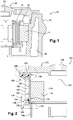
figure 3A est une vue schématique à plus grande échelle de la zone rectangulaire délimitée en pointillée sur lafigure 2 ; - la
figure 3B est une vue similaire à lafigure 3A sans le joint annulaire ; - la
figure 4A est une vue schématique à plus grande échelle de la zone ovale délimitée en pointillée sur lafigure 2 ; - la
figure 4B est une vue similaire à lafigure 4A sans les joints annulaires ; - la
figure 5 est une vue schématique en coupe d'une seconde réalisation de l'invention.
- the
figure 1 , described above, is a schematic sectional view of an electric machine according to the prior art; - the
figure 2 is a schematic half-sectional view of an electric machine according to a first embodiment of the invention; - the
figure 3A is a schematic view on a larger scale of the rectangular zone bounded in dotted line on thefigure 2 ; - the
figure 3B is a view similar to thefigure 3A without the annular seal; - the
Figure 4A is a schematic view on a larger scale of the oval area bounded in dotted line on thefigure 2 ; - the
Figure 4B is a view similar to theFigure 4A without the annular seals; - the
figure 5 is a schematic sectional view of a second embodiment of the invention.
On se réfère simultanément aux
La machine électrique selon l'invention est configurée pour empêcher la propagation des fréquences créée par les efforts électromagnétiques appliqués au stator et au rotor, efforts qui conduisent à des microdéplacements du rotor et du stator relativement l'un à l'autre à des hautes fréquences audibles, typiquement entre 1000 et 20000Hz.The electric machine according to the invention is configured to prevent the propagation of the frequencies created by the electromagnetic forces applied to the stator and the rotor, forces which lead to microdetrations of the rotor and the stator relatively to one another at high frequencies. audible, typically between 1000 and 20000Hz.
Comme expliqué précédemment, ces vibrations qui sont transmises par le stator au carter solidaire du bâti structural du véhicule automobile, induisent une augmentation du fond sonore audible dans l'environnement immédiat du véhicule.As explained above, these vibrations which are transmitted by the stator to the housing integral with the structural frame of the motor vehicle, induce an increase in audible background noise in the immediate environment of the vehicle.
Pour cela, l'invention consiste à découpler le stator 114 du reste de la machine électrique par l'utilisation de moyens élastiquement déformables.For this, the invention consists in decoupling the
Ainsi, aucun contact rigide n'existe entre le stator 114 et le reste de la machine électrique ce qui permet de stopper correctement le bruit.Thus, no rigid contact exists between the
Plus précisément, dans la machine électrique selon l'invention 100 le carter 118 entourant le stator 114 du moteur électrique est réalisé en deux pièces distinctes que sont la première pièce 126 et la seconde pièce 128.More precisely, in the electrical machine according to the
Selon un mode de réalisation, la première pièce 126 et la seconde pièce 128_ sont des pièces annulaires. La première pièce 126 définit intérieurement un logement 116 recevant le stator 114 et le rotor (non représenté) de manière similaire à ce qui a été décrit en référence à la
Selon un mode de réalisation de l'invention, le logement 116 recevant le stator 114 et le rotor, est tubulaire.According to one embodiment of the invention, the
Selon un mode de réalisation, la première pièce 126 annulaire comprend une paroi cylindrique 130 ayant pour axe 132 celui du logement 116. La première pièce 126 comprend une première extrémité 134 longitudinale et une seconde extrémité 136 longitudinale, selon l'axe 132, la seconde extrémité 136 étant agencée en vis-à-vis du couvercle 122. Dans la description, le terme « radialement » est utilisé en référence à l'axe 132 du logement 116. Un rebord annulaire 138 s'étendant radialement vers l'intérieur est formé au niveau de la première extrémité 136 longitudinale de la paroi cylindrique de la première pièce 126. Ce rebord annulaire radial 138 est agencé en vis-à-vis longitudinal d'un épaulement 140 annulaire interne radial de la seconde pièce 128 sans toutefois être en contact avec celui-ci pour éviter une transmission des vibrations de la première pièce 126 vers la seconde pièce 128 comme cela apparaitra plus clairement ultérieurement.According to one embodiment, the first
Selon un mode de réalisation, la première extrémité 134 de la première pièce 126 comprend une portion annulaire 142 en L formée par une portion d'extrémité 142a de la paroi cylindrique 130 et un rebord annulaire radial 142b s'étendant radialement vers l'extérieur (
Selon un mode de réalisation, la seconde pièce annulaire 128 comprend une première extrémité 146 et une seconde extrémité 148, la seconde extrémité 148 étant agencée en vis-à-vis du couvercle 122. La première extrémité 146 de la seconde pièce 128 se prolonge au niveau de l'épaulement annulaire 140 par une paroi cylindrique 150. La seconde pièce 128 comprend une paroi cylindrique 152 comportant à sa première extrémité 146 un renflement annulaire 154 radialement interne comportant une face 156 annulaire inclinée en oblique de manière à ce que la normale 156a à cette face 156 soit orientée en direction du couvercle 122 et de l'axe longitudinal 132. Cette face 156 est agencée en vis-à-vis du renfoncement annulaire 142c en L de la première extrémité 136 de la première pièce 126. La seconde extrémité 148 de la seconde pièce 128 comprend une portion 160 en L formée par une portion d'extrémité cylindrique 160a et un rebord annulaire radial 160b s'étendant radialement vers l'extérieur. Cette portion annulaire 160 en L de la seconde extrémité 148 de la seconde pièce 128 délimite radialement vers l'extérieur un renfoncement annulaire 160c en L. Cette portion 160 en L de la seconde extrémité 148 de la seconde pièce 128 est orientée dans l'espace de la même façon que la portion 144 en L de la seconde extrémité 136 de la première pièce 126 et est agencée longitudinalement à la même position le long de l'axe 132.According to one embodiment, the second
Selon un mode de réalisation, le couvercle 122 comprend deux nervures annulaires radialement interne 162 et radialement externe 164 en saillie à l'intérieur du logement 116 comprenant chacune une face annulaire 166, 168 inclinée en oblique par rapport à l'axe 132. Les normales 166a, 168a aux faces annulaires 166, 168 des nervures internes 162 et externe 164 sont orientées en direction de l'axe longitudinal 132. Chacune de ces normales 166a, 168a convergent vers la normale 156 à la face annulaire 156 de la première extrémité 136 de la paroi cylindrique 130 de la seconde pièce 126, en direction de l'axe 132 du logement 116. Les normales 166a, 168a des faces annulaires 166, 168 des nervures 162, 164 sont sensiblement parallèles entre elles.According to one embodiment, the
Selon un mode de réalisation, les nervures 162, 164 du couvercle 122 sont positionnées et dimensionnés de manière à ce que la face annulaire 168 de la nervure externe 164 vienne en vis-à-vis du renfoncement annulaire 160c en L de la seconde extrémité 148 de la seconde pièce et à ce que la face annuaire 166 de la nervure interne 162 vienne en vis-à-vis du renfoncement annulaire 144c en L de la seconde extrémité 136 de la première pièce 126.According to one embodiment, the
Selon l'invention, des moyens élastiquement déformables sont montés dans les renfoncements annulaires 142c, 144c, 160c des portions 142, 144, 160, en L de manière à être intercalés entre les faces annulaires 156, 166, 168 de la seconde pièce 128 et du couvercle 122 et les portions 142, 144, 160 en L des première pièce 126 et seconde pièce 128. Ces moyens élastiquement déformables sont par exemple des joints annulaires 170, s'étendant sur 360°, qui peuvent être réalisés en élastomère. Ces joints annulaires 170 ont une section circulaire mais d'autres formes pourraient également convenir.According to the invention, elastically deformable means are mounted in the
La réalisation de la
Dans une autre variante, la portion 142 en L de la première extrémité 134 de la première pièce 126 pourrait être formée sur la première extrémité 146 de la seconde pièce 128, la première extrémité 134 de la première pièce 126 comprenant alors une face inclinée pour l'appui du joint annulaire 170. De même, la portion 144 en L de la seconde extrémité 136 de la première pièce 126 pourrait être formée sur la nervure interne 162 du couvercle 122, la seconde extrémité 136 de la première pièce 126 comprenant alors une face inclinée pour l'appui du joint annulaire 170. Egalement, la portion 160 en L de la seconde extrémité 148 de la seconde pièce 128 pourrait être formée sur la nervure externe 164, la seconde extrémité 148 de la seconde pièce 128 comprenant alors une face inclinée pour l'appui du joint annulaire 170.In another variant, the L-shaped
Dans une seconde réalisation de l'invention représentée en
Selon un mode de réalisation, chaque gorge annulaire 180 loge un joint annulaire 170 similaire à ce qui a ceux décrits en référence à la précédente réalisation. Les joints annulaires 170 des gorges annulaires 180 de la première extrémité 134 de la première pièce 174 sont en appui sur des faces radiale et cylindrique de la seconde pièce 186 tandis que les joints annulaires 170 des gorges annulaires 180 de la seconde extrémité 136 de la première pièce 174 sont en appui sur une face du couvercle 122 et sur une face radiale de la nervure interne 172. La seconde extrémité 148 de la seconde pièce 186 est reliée à étanchéité et amortissement des vibrations par un joint annulaire 170 de manière similaire à ce qui a été décrit en référence à la figue 2.According to one embodiment, each
Dans les réalisations représentées aux figures, les joints annulaires 170 sont dimensionnés de manière à ce qu'il n'y ait aucun contact entre la première pièce 126, 174 et la seconde pièce 128, 186.In the embodiments shown in the figures, the
Ainsi, dans les différentes réalisations de l'invention, l'interposition de moyens élastiquement déformables entre les première pièce 126, 174 et seconde pièce 128, 186 permet de réaliser un découplage statique de la première pièce 126, 174 supportant le stator 114 du moteur électrique d'avec la seconde pièce 128, 186, ce qui permet d'éviter la transmissions des vibrations intrinsèques au fonctionnement du moteur électrique jusqu'au bâti du véhicule automobile puis à l'habitacle.Thus, in the various embodiments of the invention, the interposition of elastically deformable means between the
Claims (10)
Applications Claiming Priority (1)
| Application Number | Priority Date | Filing Date | Title |
|---|---|---|---|
| FR1661479A FR3059488A1 (en) | 2016-11-25 | 2016-11-25 | ELECTRIC MACHINE FOR A MOTOR VEHICLE |
Publications (1)
| Publication Number | Publication Date |
|---|---|
| EP3327905A1 true EP3327905A1 (en) | 2018-05-30 |
Family
ID=59520940
Family Applications (1)
| Application Number | Title | Priority Date | Filing Date |
|---|---|---|---|
| EP17203499.3A Withdrawn EP3327905A1 (en) | 2016-11-25 | 2017-11-24 | Electric machine for a motor vehicle |
Country Status (2)
| Country | Link |
|---|---|
| EP (1) | EP3327905A1 (en) |
| FR (1) | FR3059488A1 (en) |
Citations (5)
| Publication number | Priority date | Publication date | Assignee | Title |
|---|---|---|---|---|
| JP2001280501A (en) * | 2000-03-31 | 2001-10-10 | Sanyo Denki Co Ltd | Sealing structure and dynamo-electric machine |
| DE10141892A1 (en) * | 2001-08-28 | 2003-03-20 | Bosch Gmbh Robert | Electrical generator for automobile, has liquid cooling circuit defined by one rotor bearing plate with flow-cross-section limited by second rotor bearing plate |
| DE10142174A1 (en) * | 2001-08-29 | 2003-03-20 | Bosch Gmbh Robert | Electric motor for ventilation fan for automobile air-conditioning device, has integral fixings for securing motor housing in cylindrical seating |
| EP2093865A2 (en) * | 2008-02-25 | 2009-08-26 | Sanyo Denki Co., Ltd. | Airtight-type electric motor |
| WO2014016063A2 (en) * | 2012-07-25 | 2014-01-30 | Siemens Aktiengesellschaft | Cooling jacket comprising a sealing means |
-
2016
- 2016-11-25 FR FR1661479A patent/FR3059488A1/en active Pending
-
2017
- 2017-11-24 EP EP17203499.3A patent/EP3327905A1/en not_active Withdrawn
Patent Citations (5)
| Publication number | Priority date | Publication date | Assignee | Title |
|---|---|---|---|---|
| JP2001280501A (en) * | 2000-03-31 | 2001-10-10 | Sanyo Denki Co Ltd | Sealing structure and dynamo-electric machine |
| DE10141892A1 (en) * | 2001-08-28 | 2003-03-20 | Bosch Gmbh Robert | Electrical generator for automobile, has liquid cooling circuit defined by one rotor bearing plate with flow-cross-section limited by second rotor bearing plate |
| DE10142174A1 (en) * | 2001-08-29 | 2003-03-20 | Bosch Gmbh Robert | Electric motor for ventilation fan for automobile air-conditioning device, has integral fixings for securing motor housing in cylindrical seating |
| EP2093865A2 (en) * | 2008-02-25 | 2009-08-26 | Sanyo Denki Co., Ltd. | Airtight-type electric motor |
| WO2014016063A2 (en) * | 2012-07-25 | 2014-01-30 | Siemens Aktiengesellschaft | Cooling jacket comprising a sealing means |
Also Published As
| Publication number | Publication date |
|---|---|
| FR3059488A1 (en) | 2018-06-01 |
Similar Documents
| Publication | Publication Date | Title |
|---|---|---|
| FR3015380A1 (en) | TRANSMISSION ASSEMBLY FOR A HYBRID VEHICLE EQUIPPED WITH A PENDULAR SHOCK ABSORBER | |
| EP2140178A2 (en) | Double seal with pressurised lip | |
| CA2754090A1 (en) | Rotor element with a fluid passage and passage-blocking member, and turbine engine including the rotor element | |
| EP0511105A1 (en) | Rollbearing with speed sensor | |
| CA2646976A1 (en) | Bearing bracket sealed fitting in a turbine engine | |
| FR2881382A1 (en) | Reversible rotating machine rotor and transmission input shaft coupling device for motor vehicle, has rotor with hub whose one end is arranged against bearing of transmission and centered on shaft by plain bearing | |
| WO2015162386A1 (en) | Torque transmission device for a motor vehicle | |
| EP3327905A1 (en) | Electric machine for a motor vehicle | |
| WO2014202898A1 (en) | Turbomachine accessory gearbox equipped with a centrifugal pump | |
| FR2798530A1 (en) | DRIVE SYSTEM INCLUDING AN ARRANGEMENT FOR DAMPING TORSIONAL OSCILLATIONS BETWEEN A ROTOR AND A STATOR | |
| FR2885393A1 (en) | Torque transmission device for engine, has rotating shaft extended outside water tight joint, rotating units facing each other to form covering in space between them, sealing device closing space leading towards exterior of clutch | |
| FR3057931B1 (en) | COUPLER TORQUE TRANSMISSION DEVICE FOR A MOTOR VEHICLE | |
| FR3066533B1 (en) | SEALING ASSEMBLY FOR A TURBOMACHINE | |
| EP1200751A1 (en) | Disc for rigid friction clutch | |
| FR2767370A1 (en) | Vehicle automatic transmission torque converter with locking clutch | |
| WO2018104139A1 (en) | Torsion damping device | |
| EP3997317A1 (en) | Assembly for retaining a gear train in a turbomachine | |
| FR3087511A1 (en) | SHOCK ABSORBER | |
| WO2024078947A1 (en) | Ventilation device comprising retention means | |
| FR3140656A1 (en) | Ventilation device comprising retention means | |
| FR3059060A1 (en) | DEVICE FOR MAINTAINING AN ELECTRIC MOTOR IN AN ACTUATOR BODY | |
| FR2886697A1 (en) | SEALING DEVICE FOR CLUTCH COVER | |
| FR2987069A1 (en) | AUBEE RADIAL WHEEL WITH RADIAL FREE BASE CROWN | |
| FR2752028A1 (en) | VISCOUS FRICTION CLUTCH | |
| FR3105328A1 (en) | Torque transmission device |
Legal Events
| Date | Code | Title | Description |
|---|---|---|---|
| PUAI | Public reference made under article 153(3) epc to a published international application that has entered the european phase |
Free format text: ORIGINAL CODE: 0009012 |
|
| 17P | Request for examination filed |
Effective date: 20171124 |
|
| AK | Designated contracting states |
Kind code of ref document: A1 Designated state(s): AL AT BE BG CH CY CZ DE DK EE ES FI FR GB GR HR HU IE IS IT LI LT LU LV MC MK MT NL NO PL PT RO RS SE SI SK SM TR |
|
| AX | Request for extension of the european patent |
Extension state: BA ME |
|
| STAA | Information on the status of an ep patent application or granted ep patent |
Free format text: STATUS: THE APPLICATION IS DEEMED TO BE WITHDRAWN |
|
| 18D | Application deemed to be withdrawn |
Effective date: 20181201 |