EP3327770A1 - Kühlkörpersteckerstift und anordnung - Google Patents
Kühlkörpersteckerstift und anordnung Download PDFInfo
- Publication number
- EP3327770A1 EP3327770A1 EP16204147.9A EP16204147A EP3327770A1 EP 3327770 A1 EP3327770 A1 EP 3327770A1 EP 16204147 A EP16204147 A EP 16204147A EP 3327770 A1 EP3327770 A1 EP 3327770A1
- Authority
- EP
- European Patent Office
- Prior art keywords
- substrate
- heat sink
- pin
- fingers
- sleeve
- Prior art date
- Legal status (The legal status is an assumption and is not a legal conclusion. Google has not performed a legal analysis and makes no representation as to the accuracy of the status listed.)
- Granted
Links
Images


Classifications
-
- H—ELECTRICITY
- H05—ELECTRIC TECHNIQUES NOT OTHERWISE PROVIDED FOR
- H05K—PRINTED CIRCUITS; CASINGS OR CONSTRUCTIONAL DETAILS OF ELECTRIC APPARATUS; MANUFACTURE OF ASSEMBLAGES OF ELECTRICAL COMPONENTS
- H05K7/00—Constructional details common to different types of electric apparatus
- H05K7/20—Modifications to facilitate cooling, ventilating, or heating
- H05K7/2039—Modifications to facilitate cooling, ventilating, or heating characterised by the heat transfer by conduction from the heat generating element to a dissipating body
- H05K7/20436—Inner thermal coupling elements in heat dissipating housings, e.g. protrusions or depressions integrally formed in the housing
- H05K7/2049—Pressing means used to urge contact, e.g. springs
-
- H—ELECTRICITY
- H10—SEMICONDUCTOR DEVICES; ELECTRIC SOLID-STATE DEVICES NOT OTHERWISE PROVIDED FOR
- H10W—GENERIC PACKAGES, INTERCONNECTIONS, CONNECTORS OR OTHER CONSTRUCTIONAL DETAILS OF DEVICES COVERED BY CLASS H10
- H10W40/00—Arrangements for thermal protection or thermal control
- H10W40/60—Securing means for detachable heating or cooling arrangements, e.g. clamps
-
- F—MECHANICAL ENGINEERING; LIGHTING; HEATING; WEAPONS; BLASTING
- F16—ENGINEERING ELEMENTS AND UNITS; GENERAL MEASURES FOR PRODUCING AND MAINTAINING EFFECTIVE FUNCTIONING OF MACHINES OR INSTALLATIONS; THERMAL INSULATION IN GENERAL
- F16B—DEVICES FOR FASTENING OR SECURING CONSTRUCTIONAL ELEMENTS OR MACHINE PARTS TOGETHER, e.g. NAILS, BOLTS, CIRCLIPS, CLAMPS, CLIPS OR WEDGES; JOINTS OR JOINTING
- F16B19/00—Bolts without screw-thread; Pins, including deformable elements; Rivets
- F16B19/04—Rivets; Spigots or the like fastened by riveting
- F16B19/08—Hollow rivets; Multi-part rivets
- F16B19/10—Hollow rivets; Multi-part rivets fastened by expanding mechanically
- F16B19/1027—Multi-part rivets
- F16B19/1036—Blind rivets
- F16B19/109—Temporary rivets, e.g. with a spring-loaded pin
-
- F—MECHANICAL ENGINEERING; LIGHTING; HEATING; WEAPONS; BLASTING
- F16—ENGINEERING ELEMENTS AND UNITS; GENERAL MEASURES FOR PRODUCING AND MAINTAINING EFFECTIVE FUNCTIONING OF MACHINES OR INSTALLATIONS; THERMAL INSULATION IN GENERAL
- F16B—DEVICES FOR FASTENING OR SECURING CONSTRUCTIONAL ELEMENTS OR MACHINE PARTS TOGETHER, e.g. NAILS, BOLTS, CIRCLIPS, CLAMPS, CLIPS OR WEDGES; JOINTS OR JOINTING
- F16B5/00—Joining sheets or plates, e.g. panels, to one another or to strips or bars parallel to them
- F16B5/02—Joining sheets or plates, e.g. panels, to one another or to strips or bars parallel to them by means of fastening members using screw-thread
- F16B5/0266—Joining sheets or plates, e.g. panels, to one another or to strips or bars parallel to them by means of fastening members using screw-thread using springs
-
- H—ELECTRICITY
- H05—ELECTRIC TECHNIQUES NOT OTHERWISE PROVIDED FOR
- H05K—PRINTED CIRCUITS; CASINGS OR CONSTRUCTIONAL DETAILS OF ELECTRIC APPARATUS; MANUFACTURE OF ASSEMBLAGES OF ELECTRICAL COMPONENTS
- H05K1/00—Printed circuits
- H05K1/02—Details
- H05K1/0201—Thermal arrangements, e.g. for cooling, heating or preventing overheating
- H05K1/0203—Cooling of mounted components
-
- H—ELECTRICITY
- H05—ELECTRIC TECHNIQUES NOT OTHERWISE PROVIDED FOR
- H05K—PRINTED CIRCUITS; CASINGS OR CONSTRUCTIONAL DETAILS OF ELECTRIC APPARATUS; MANUFACTURE OF ASSEMBLAGES OF ELECTRICAL COMPONENTS
- H05K7/00—Constructional details common to different types of electric apparatus
- H05K7/20—Modifications to facilitate cooling, ventilating, or heating
- H05K7/20009—Modifications to facilitate cooling, ventilating, or heating using a gaseous coolant in electronic enclosures
- H05K7/20136—Forced ventilation, e.g. by fans
- H05K7/20154—Heat dissipaters coupled to components
-
- H—ELECTRICITY
- H10—SEMICONDUCTOR DEVICES; ELECTRIC SOLID-STATE DEVICES NOT OTHERWISE PROVIDED FOR
- H10W—GENERIC PACKAGES, INTERCONNECTIONS, CONNECTORS OR OTHER CONSTRUCTIONAL DETAILS OF DEVICES COVERED BY CLASS H10
- H10W40/00—Arrangements for thermal protection or thermal control
- H10W40/20—Arrangements for cooling
- H10W40/22—Arrangements for cooling characterised by their shape, e.g. having conical or cylindrical projections
- H10W40/226—Arrangements for cooling characterised by their shape, e.g. having conical or cylindrical projections characterised by projecting parts, e.g. fins to increase surface area
-
- H—ELECTRICITY
- H10—SEMICONDUCTOR DEVICES; ELECTRIC SOLID-STATE DEVICES NOT OTHERWISE PROVIDED FOR
- H10W—GENERIC PACKAGES, INTERCONNECTIONS, CONNECTORS OR OTHER CONSTRUCTIONAL DETAILS OF DEVICES COVERED BY CLASS H10
- H10W40/00—Arrangements for thermal protection or thermal control
- H10W40/60—Securing means for detachable heating or cooling arrangements, e.g. clamps
- H10W40/641—Snap-on arrangements, e.g. clips
-
- F—MECHANICAL ENGINEERING; LIGHTING; HEATING; WEAPONS; BLASTING
- F16—ENGINEERING ELEMENTS AND UNITS; GENERAL MEASURES FOR PRODUCING AND MAINTAINING EFFECTIVE FUNCTIONING OF MACHINES OR INSTALLATIONS; THERMAL INSULATION IN GENERAL
- F16B—DEVICES FOR FASTENING OR SECURING CONSTRUCTIONAL ELEMENTS OR MACHINE PARTS TOGETHER, e.g. NAILS, BOLTS, CIRCLIPS, CLAMPS, CLIPS OR WEDGES; JOINTS OR JOINTING
- F16B21/00—Means for preventing relative axial movement of a pin, spigot, shaft or the like and a member surrounding it; Stud-and-socket releasable fastenings
- F16B21/10—Means for preventing relative axial movement of a pin, spigot, shaft or the like and a member surrounding it; Stud-and-socket releasable fastenings by separate parts
- F16B21/12—Means for preventing relative axial movement of a pin, spigot, shaft or the like and a member surrounding it; Stud-and-socket releasable fastenings by separate parts with locking-pins or split-pins thrust into holes
-
- H—ELECTRICITY
- H05—ELECTRIC TECHNIQUES NOT OTHERWISE PROVIDED FOR
- H05K—PRINTED CIRCUITS; CASINGS OR CONSTRUCTIONAL DETAILS OF ELECTRIC APPARATUS; MANUFACTURE OF ASSEMBLAGES OF ELECTRICAL COMPONENTS
- H05K2201/00—Indexing scheme relating to printed circuits covered by H05K1/00
- H05K2201/06—Thermal details
- H05K2201/066—Heatsink mounted on the surface of the printed circuit board [PCB]
-
- H—ELECTRICITY
- H05—ELECTRIC TECHNIQUES NOT OTHERWISE PROVIDED FOR
- H05K—PRINTED CIRCUITS; CASINGS OR CONSTRUCTIONAL DETAILS OF ELECTRIC APPARATUS; MANUFACTURE OF ASSEMBLAGES OF ELECTRICAL COMPONENTS
- H05K2201/00—Indexing scheme relating to printed circuits covered by H05K1/00
- H05K2201/09—Shape and layout
- H05K2201/09009—Substrate related
- H05K2201/09063—Holes or slots in insulating substrate not used for electrical connections
-
- H—ELECTRICITY
- H10—SEMICONDUCTOR DEVICES; ELECTRIC SOLID-STATE DEVICES NOT OTHERWISE PROVIDED FOR
- H10W—GENERIC PACKAGES, INTERCONNECTIONS, CONNECTORS OR OTHER CONSTRUCTIONAL DETAILS OF DEVICES COVERED BY CLASS H10
- H10W40/00—Arrangements for thermal protection or thermal control
- H10W40/60—Securing means for detachable heating or cooling arrangements, e.g. clamps
- H10W40/611—Bolts or screws
Definitions
- a heat sink connector pin for attaching a heatsink to a top surface of a substrate and in thermal contact with a heat dissipating device, includes a pin assembly having a pin head at a fist end and a plurality of moveable fingers at a second end.
- a shaft structure is operably engaged to the moveable fingers and to the pin head.
- the shaft structure is configured for downward movement, via rotational movement of pin head, pressing down on the pin head or any other suitable action causing downward movement of the shaft structure.
- the plurality of moveable fingers are configured to be in a retracted position that allows insertion of the second end through an opening in the substrate without deforming the plurality of movable fingers.
- the fingers are also configured to mechanically move outward to an extended position in a manner that positions the plurality of fingers to contact a bottom surface of the substrate, in response to downward movement of the shaft structure.
- the moveable fingers have a substrate engagement surface adapted to engage a bottom surface of the substrate when in the outward extended position.
- the pin assembly includes a sleeve adapted to receive the shaft structure and is adapted to engage with the pin head.
- the sleeve includes a substrate stop surface adapted to contact a top surface of the substrate during insertion of the second end through the substrate opening.
- the pin head has a shape so that the user can determine whether a heat sink connector pin is properly installed.
- a compression spring is employed, rotating or turning the pin head causes the compression of the spring which can further cause an upward force to be applied by the outwardly extended fingers, however any suitable structure may be employed.
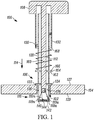
- FIG. 1 is a cross sectional view illustrating one example of a heat sink connector pin 100 that is being inserted through an opening 102 of a substrate 104 such as a printed circuit board, chip carrier, or any other suitable substrate.
- a heat sink see FIG. 5
- a heat sink coupling portion 106 that engages with an arm of a heat sink is employed however, such a portion may not be necessary depending upon the design of the heat sink. For example, there would be no need if the heat sink does not include attachment arms and instead includes through-holes through another portion of the heat sink.
- the fingers 110a-110n are then extended outward to grasp the bottom surface 129 of the substrate 104.
- the heels of the fingers contact the surface 142 pushing the fingers outward.
- the surface 142 may not be needed depending on the design as long as the fingers 110a-110n are caused to extend outwardly.
- the shape of the pin head 108 at the top of the pin head is shaped in a manner that allows a user to visually identify that the pin head 102 has been rotated thereby indicating proper installation. To remove the pin from a heat sink assembly, the pin head is rotated in the opposite direction.
- the shaft 112 is secured for vertical (axial) movement with pin head but not rotational movement via a "C" clamp or other suitable structure inside the pin head area that receives the end of the shaft.
- a "C” clamp or other suitable structure inside the pin head area that receives the end of the shaft.
- a heat sink assembly 402 is shown illustrating the substrate 102 that supports a heat generating device 404 which in this example is shown to be a microprocessor, APU, GPU, or any other suitable integrated circuit.
- the integrated circuit is in a package that is also shown to be in a carrier 406 although any suitable heat dissipating device may benefit.
- a heat sink 408 is in thermal contact with the heat generating device 404 when placed in contact with the heat dissipating device through any suitable heat conducting members if a direct connection is not employed.
- the heat sink connector pins 100 are inserted through the through-holes 102 of the substrate and are configured to affix the heat sink 408 to the substrate 104.
- a fan assembly 410 is also shown to be affixed to the heat sink through attachment screws 412.
- the heat sink connector pins are of the type described above with reference to FIGs. 1 and 2 .
- one or more embodiments simplifies the installation experience and can improve installation time using a system that has bottom fingers that automatically grab onto the bottom of the substrate with little vertical compressive force.
- a user may simply insert the heat sink connector pin into the heat sink and substrate and rotate the pin head to engage the fingers to the bottom surface of the substrate and rotate the pin head on an opposite direction to remove retract the moveable fingers.
- Non rotational mechanisms may also be used.
Landscapes
- Engineering & Computer Science (AREA)
- General Engineering & Computer Science (AREA)
- Microelectronics & Electronic Packaging (AREA)
- Mechanical Engineering (AREA)
- Physics & Mathematics (AREA)
- Thermal Sciences (AREA)
- Cooling Or The Like Of Electrical Apparatus (AREA)
- Cooling Or The Like Of Semiconductors Or Solid State Devices (AREA)
- Theoretical Computer Science (AREA)
- Dowels (AREA)
- Mounting Components In General For Electric Apparatus (AREA)
- General Physics & Mathematics (AREA)
- Human Computer Interaction (AREA)
Applications Claiming Priority (1)
| Application Number | Priority Date | Filing Date | Title |
|---|---|---|---|
| US15/362,064 US10117356B2 (en) | 2016-11-28 | 2016-11-28 | Heat sink connector pin and assembly |
Publications (2)
| Publication Number | Publication Date |
|---|---|
| EP3327770A1 true EP3327770A1 (de) | 2018-05-30 |
| EP3327770B1 EP3327770B1 (de) | 2019-03-06 |
Family
ID=57799449
Family Applications (1)
| Application Number | Title | Priority Date | Filing Date |
|---|---|---|---|
| EP16204147.9A Active EP3327770B1 (de) | 2016-11-28 | 2016-12-14 | Kühlkörpersteckerstift und anordnung |
Country Status (6)
| Country | Link |
|---|---|
| US (1) | US10117356B2 (de) |
| EP (1) | EP3327770B1 (de) |
| JP (1) | JP7106536B2 (de) |
| KR (1) | KR102443652B1 (de) |
| CN (1) | CN109891581B (de) |
| WO (1) | WO2018098456A1 (de) |
Families Citing this family (3)
| Publication number | Priority date | Publication date | Assignee | Title |
|---|---|---|---|---|
| CN113251047A (zh) * | 2021-04-29 | 2021-08-13 | 成都飞机工业(集团)有限责任公司 | 一种可单边操作的安全插销及其使用方法 |
| US11758690B2 (en) * | 2021-06-18 | 2023-09-12 | Nanning Fulian Fugui Precision Industrial Co., Ltd. | Heat-dissipation device allowing easy detachment from heat-generating component |
| US12471221B2 (en) * | 2022-10-21 | 2025-11-11 | Raytheon Company | Clamping device with pivoting retainer |
Citations (1)
| Publication number | Priority date | Publication date | Assignee | Title |
|---|---|---|---|---|
| US20110194257A1 (en) * | 2010-02-05 | 2011-08-11 | Fu Tai Hua Industry (Shenzhen) Co., Ltd. | Fixing device and heat sink assembly using the same |
Family Cites Families (21)
| Publication number | Priority date | Publication date | Assignee | Title |
|---|---|---|---|---|
| US4213642A (en) * | 1979-02-12 | 1980-07-22 | Hartwell Corporation | Rotary latch and method of operation |
| US4760495A (en) * | 1987-04-16 | 1988-07-26 | Prime Computer Inc. | Stand-off device |
| US5199733A (en) * | 1991-09-09 | 1993-04-06 | Delorme Glen E | Safety hitch pin |
| US5517734A (en) * | 1995-04-10 | 1996-05-21 | Korpi; John G. | Quick fastener |
| US5870286A (en) | 1997-08-20 | 1999-02-09 | International Business Machines Corporation | Heat sink assembly for cooling electronic modules |
| US6118659A (en) * | 1998-03-09 | 2000-09-12 | International Business Machines Corporation | Heat sink clamping spring additionally holding a ZIF socket locked |
| US6752577B2 (en) * | 2002-02-27 | 2004-06-22 | Shu-Chen Teng | Heat sink fastener |
| KR100457220B1 (ko) | 2002-02-27 | 2004-11-16 | 잘만테크 주식회사 | 칩셋 냉각용 히트싱크장치 |
| JP3894070B2 (ja) | 2002-08-06 | 2007-03-14 | 富士通株式会社 | ヒートシンク、ヒートシンク装置、該ヒートシンクの固定方法及び該ヒートシンクを使用した電子装置 |
| US20040238947A1 (en) | 2003-05-28 | 2004-12-02 | Intel Corporation | Package and method for attaching an integrated heat spreader |
| US20050072558A1 (en) | 2003-10-03 | 2005-04-07 | Aavid Thermalloy, Llc | Heat sink assembly and connecting device |
| TWM248206U (en) * | 2003-10-17 | 2004-10-21 | Hon Hai Prec Ind Co Ltd | Clip for heat sink |
| US7516948B2 (en) * | 2004-04-02 | 2009-04-14 | Phd, Inc. | Pin clamp accessories |
| JP4212511B2 (ja) * | 2004-05-06 | 2009-01-21 | 富士通株式会社 | 半導体装置及び半導体装置の組立方法 |
| US7489511B2 (en) * | 2006-12-28 | 2009-02-10 | Hon Hai Precision Industry Co., Ltd. | Heat sink clip |
| US7852633B2 (en) * | 2008-07-24 | 2010-12-14 | Yamaichi Electronics Co., Ltd. | Connector for connection to a module board |
| DE102009002992B4 (de) * | 2009-05-11 | 2014-10-30 | Infineon Technologies Ag | Leistungshalbleitermodulanordnung mit eindeutig und verdrehsicher auf einem Kühlkörper montierbarem Leistungshalbleitermodul und Montageverfahren |
| JP3153773U (ja) | 2009-07-08 | 2009-09-17 | 本俊 游 | 放熱モジュール用固定部材 |
| JP2011023491A (ja) | 2009-07-15 | 2011-02-03 | Nec Corp | 係止治具及び半導体装置 |
| US20110027038A1 (en) * | 2009-07-28 | 2011-02-03 | Pen-Chun YU | Heat sink anchoring apparatus |
| KR101508467B1 (ko) | 2014-09-23 | 2015-04-07 | 삼성전기주식회사 | 히트 싱크가 결합된 반도체 모듈 |
-
2016
- 2016-11-28 US US15/362,064 patent/US10117356B2/en active Active
- 2016-12-14 EP EP16204147.9A patent/EP3327770B1/de active Active
-
2017
- 2017-11-28 CN CN201780066991.5A patent/CN109891581B/zh active Active
- 2017-11-28 JP JP2019528492A patent/JP7106536B2/ja active Active
- 2017-11-28 KR KR1020197012083A patent/KR102443652B1/ko active Active
- 2017-11-28 WO PCT/US2017/063367 patent/WO2018098456A1/en not_active Ceased
Patent Citations (1)
| Publication number | Priority date | Publication date | Assignee | Title |
|---|---|---|---|---|
| US20110194257A1 (en) * | 2010-02-05 | 2011-08-11 | Fu Tai Hua Industry (Shenzhen) Co., Ltd. | Fixing device and heat sink assembly using the same |
Also Published As
| Publication number | Publication date |
|---|---|
| JP2020501354A (ja) | 2020-01-16 |
| EP3327770B1 (de) | 2019-03-06 |
| JP7106536B2 (ja) | 2022-07-26 |
| KR20190082204A (ko) | 2019-07-09 |
| WO2018098456A1 (en) | 2018-05-31 |
| CN109891581A (zh) | 2019-06-14 |
| US10117356B2 (en) | 2018-10-30 |
| US20180150114A1 (en) | 2018-05-31 |
| CN109891581B (zh) | 2022-12-30 |
| KR102443652B1 (ko) | 2022-09-15 |
Similar Documents
| Publication | Publication Date | Title |
|---|---|---|
| US7180743B2 (en) | Fastener for heat sink | |
| US7283368B2 (en) | Heat dissipating assembly | |
| EP3327770B1 (de) | Kühlkörpersteckerstift und anordnung | |
| US20070217159A1 (en) | Clip assembly for attaching a heat sink to an electronic device | |
| CN1848035A (zh) | 锁固组件 | |
| US8422233B2 (en) | Motherboard system having heat dissipating device | |
| US5999402A (en) | Heat sink fastener retention apparatus and method for computer systems | |
| CN101825937A (zh) | 散热装置 | |
| CN101541155A (zh) | 散热装置组合 | |
| US20060067053A1 (en) | Locking device for heat dissipating device | |
| US20110149506A1 (en) | Adjustable mounting bracket for a computer component | |
| US11800634B2 (en) | Heat sink fastening structure | |
| US20080158828A1 (en) | Heatsink structure and assembly fixture thereof | |
| US9917033B2 (en) | Multicomponent heat sink with movable fin support portion | |
| US7315449B2 (en) | Apparatus for supporting a heatsink | |
| US20110108234A1 (en) | Fastening device and heat dissipation apparatus using the same | |
| CN101309569A (zh) | 扣具及散热装置组合 | |
| US7405938B2 (en) | Heat sink clip | |
| US6822870B2 (en) | Retaining apparatus | |
| US20040233617A1 (en) | Component retention mechanism and method | |
| CN101193536A (zh) | 散热器结构及其组装治具 | |
| CN216775289U (zh) | 一种双层电路板卡接固定结构 | |
| TWM519264U (zh) | 微處理器之扣件模組 | |
| US6616471B2 (en) | Integrated horizontal cam lever for zero-insertion force (ZIF) socket actuation | |
| JP3153773U (ja) | 放熱モジュール用固定部材 |
Legal Events
| Date | Code | Title | Description |
|---|---|---|---|
| STAA | Information on the status of an ep patent application or granted ep patent |
Free format text: STATUS: EXAMINATION IS IN PROGRESS |
|
| PUAI | Public reference made under article 153(3) epc to a published international application that has entered the european phase |
Free format text: ORIGINAL CODE: 0009012 |
|
| 17P | Request for examination filed |
Effective date: 20161214 |
|
| AK | Designated contracting states |
Kind code of ref document: A1 Designated state(s): AL AT BE BG CH CY CZ DE DK EE ES FI FR GB GR HR HU IE IS IT LI LT LU LV MC MK MT NL NO PL PT RO RS SE SI SK SM TR |
|
| AX | Request for extension of the european patent |
Extension state: BA ME |
|
| GRAP | Despatch of communication of intention to grant a patent |
Free format text: ORIGINAL CODE: EPIDOSNIGR1 |
|
| STAA | Information on the status of an ep patent application or granted ep patent |
Free format text: STATUS: GRANT OF PATENT IS INTENDED |
|
| RIC1 | Information provided on ipc code assigned before grant |
Ipc: F16B 21/12 20060101ALN20181005BHEP Ipc: F16B 19/10 20060101ALI20181005BHEP Ipc: F16B 5/02 20060101ALI20181005BHEP Ipc: H05K 7/20 20060101ALI20181005BHEP Ipc: H01L 23/40 20060101AFI20181005BHEP Ipc: H05K 1/02 20060101ALI20181005BHEP |
|
| INTG | Intention to grant announced |
Effective date: 20181029 |
|
| GRAS | Grant fee paid |
Free format text: ORIGINAL CODE: EPIDOSNIGR3 |
|
| GRAA | (expected) grant |
Free format text: ORIGINAL CODE: 0009210 |
|
| STAA | Information on the status of an ep patent application or granted ep patent |
Free format text: STATUS: THE PATENT HAS BEEN GRANTED |
|
| AK | Designated contracting states |
Kind code of ref document: B1 Designated state(s): AL AT BE BG CH CY CZ DE DK EE ES FI FR GB GR HR HU IE IS IT LI LT LU LV MC MK MT NL NO PL PT RO RS SE SI SK SM TR |
|
| REG | Reference to a national code |
Ref country code: GB Ref legal event code: FG4D |
|
| REG | Reference to a national code |
Ref country code: CH Ref legal event code: EP Ref country code: AT Ref legal event code: REF Ref document number: 1105694 Country of ref document: AT Kind code of ref document: T Effective date: 20190315 |
|
| REG | Reference to a national code |
Ref country code: DE Ref legal event code: R096 Ref document number: 602016010672 Country of ref document: DE |
|
| REG | Reference to a national code |
Ref country code: IE Ref legal event code: FG4D |
|
| REG | Reference to a national code |
Ref country code: NL Ref legal event code: MP Effective date: 20190306 |
|
| REG | Reference to a national code |
Ref country code: LT Ref legal event code: MG4D |
|
| PG25 | Lapsed in a contracting state [announced via postgrant information from national office to epo] |
Ref country code: FI Free format text: LAPSE BECAUSE OF FAILURE TO SUBMIT A TRANSLATION OF THE DESCRIPTION OR TO PAY THE FEE WITHIN THE PRESCRIBED TIME-LIMIT Effective date: 20190306 Ref country code: LT Free format text: LAPSE BECAUSE OF FAILURE TO SUBMIT A TRANSLATION OF THE DESCRIPTION OR TO PAY THE FEE WITHIN THE PRESCRIBED TIME-LIMIT Effective date: 20190306 Ref country code: NO Free format text: LAPSE BECAUSE OF FAILURE TO SUBMIT A TRANSLATION OF THE DESCRIPTION OR TO PAY THE FEE WITHIN THE PRESCRIBED TIME-LIMIT Effective date: 20190606 Ref country code: SE Free format text: LAPSE BECAUSE OF FAILURE TO SUBMIT A TRANSLATION OF THE DESCRIPTION OR TO PAY THE FEE WITHIN THE PRESCRIBED TIME-LIMIT Effective date: 20190306 |
|
| PG25 | Lapsed in a contracting state [announced via postgrant information from national office to epo] |
Ref country code: NL Free format text: LAPSE BECAUSE OF FAILURE TO SUBMIT A TRANSLATION OF THE DESCRIPTION OR TO PAY THE FEE WITHIN THE PRESCRIBED TIME-LIMIT Effective date: 20190306 Ref country code: RS Free format text: LAPSE BECAUSE OF FAILURE TO SUBMIT A TRANSLATION OF THE DESCRIPTION OR TO PAY THE FEE WITHIN THE PRESCRIBED TIME-LIMIT Effective date: 20190306 Ref country code: LV Free format text: LAPSE BECAUSE OF FAILURE TO SUBMIT A TRANSLATION OF THE DESCRIPTION OR TO PAY THE FEE WITHIN THE PRESCRIBED TIME-LIMIT Effective date: 20190306 Ref country code: BG Free format text: LAPSE BECAUSE OF FAILURE TO SUBMIT A TRANSLATION OF THE DESCRIPTION OR TO PAY THE FEE WITHIN THE PRESCRIBED TIME-LIMIT Effective date: 20190606 Ref country code: GR Free format text: LAPSE BECAUSE OF FAILURE TO SUBMIT A TRANSLATION OF THE DESCRIPTION OR TO PAY THE FEE WITHIN THE PRESCRIBED TIME-LIMIT Effective date: 20190607 Ref country code: HR Free format text: LAPSE BECAUSE OF FAILURE TO SUBMIT A TRANSLATION OF THE DESCRIPTION OR TO PAY THE FEE WITHIN THE PRESCRIBED TIME-LIMIT Effective date: 20190306 |
|
| REG | Reference to a national code |
Ref country code: AT Ref legal event code: MK05 Ref document number: 1105694 Country of ref document: AT Kind code of ref document: T Effective date: 20190306 |
|
| PG25 | Lapsed in a contracting state [announced via postgrant information from national office to epo] |
Ref country code: EE Free format text: LAPSE BECAUSE OF FAILURE TO SUBMIT A TRANSLATION OF THE DESCRIPTION OR TO PAY THE FEE WITHIN THE PRESCRIBED TIME-LIMIT Effective date: 20190306 Ref country code: SK Free format text: LAPSE BECAUSE OF FAILURE TO SUBMIT A TRANSLATION OF THE DESCRIPTION OR TO PAY THE FEE WITHIN THE PRESCRIBED TIME-LIMIT Effective date: 20190306 Ref country code: PT Free format text: LAPSE BECAUSE OF FAILURE TO SUBMIT A TRANSLATION OF THE DESCRIPTION OR TO PAY THE FEE WITHIN THE PRESCRIBED TIME-LIMIT Effective date: 20190706 Ref country code: AL Free format text: LAPSE BECAUSE OF FAILURE TO SUBMIT A TRANSLATION OF THE DESCRIPTION OR TO PAY THE FEE WITHIN THE PRESCRIBED TIME-LIMIT Effective date: 20190306 Ref country code: IT Free format text: LAPSE BECAUSE OF FAILURE TO SUBMIT A TRANSLATION OF THE DESCRIPTION OR TO PAY THE FEE WITHIN THE PRESCRIBED TIME-LIMIT Effective date: 20190306 Ref country code: ES Free format text: LAPSE BECAUSE OF FAILURE TO SUBMIT A TRANSLATION OF THE DESCRIPTION OR TO PAY THE FEE WITHIN THE PRESCRIBED TIME-LIMIT Effective date: 20190306 Ref country code: RO Free format text: LAPSE BECAUSE OF FAILURE TO SUBMIT A TRANSLATION OF THE DESCRIPTION OR TO PAY THE FEE WITHIN THE PRESCRIBED TIME-LIMIT Effective date: 20190306 Ref country code: CZ Free format text: LAPSE BECAUSE OF FAILURE TO SUBMIT A TRANSLATION OF THE DESCRIPTION OR TO PAY THE FEE WITHIN THE PRESCRIBED TIME-LIMIT Effective date: 20190306 |
|
| PG25 | Lapsed in a contracting state [announced via postgrant information from national office to epo] |
Ref country code: SM Free format text: LAPSE BECAUSE OF FAILURE TO SUBMIT A TRANSLATION OF THE DESCRIPTION OR TO PAY THE FEE WITHIN THE PRESCRIBED TIME-LIMIT Effective date: 20190306 Ref country code: PL Free format text: LAPSE BECAUSE OF FAILURE TO SUBMIT A TRANSLATION OF THE DESCRIPTION OR TO PAY THE FEE WITHIN THE PRESCRIBED TIME-LIMIT Effective date: 20190306 |
|
| REG | Reference to a national code |
Ref country code: DE Ref legal event code: R097 Ref document number: 602016010672 Country of ref document: DE |
|
| PG25 | Lapsed in a contracting state [announced via postgrant information from national office to epo] |
Ref country code: AT Free format text: LAPSE BECAUSE OF FAILURE TO SUBMIT A TRANSLATION OF THE DESCRIPTION OR TO PAY THE FEE WITHIN THE PRESCRIBED TIME-LIMIT Effective date: 20190306 Ref country code: IS Free format text: LAPSE BECAUSE OF FAILURE TO SUBMIT A TRANSLATION OF THE DESCRIPTION OR TO PAY THE FEE WITHIN THE PRESCRIBED TIME-LIMIT Effective date: 20190706 |
|
| PLBE | No opposition filed within time limit |
Free format text: ORIGINAL CODE: 0009261 |
|
| STAA | Information on the status of an ep patent application or granted ep patent |
Free format text: STATUS: NO OPPOSITION FILED WITHIN TIME LIMIT |
|
| PG25 | Lapsed in a contracting state [announced via postgrant information from national office to epo] |
Ref country code: DK Free format text: LAPSE BECAUSE OF FAILURE TO SUBMIT A TRANSLATION OF THE DESCRIPTION OR TO PAY THE FEE WITHIN THE PRESCRIBED TIME-LIMIT Effective date: 20190306 |
|
| 26N | No opposition filed |
Effective date: 20191209 |
|
| PG25 | Lapsed in a contracting state [announced via postgrant information from national office to epo] |
Ref country code: TR Free format text: LAPSE BECAUSE OF FAILURE TO SUBMIT A TRANSLATION OF THE DESCRIPTION OR TO PAY THE FEE WITHIN THE PRESCRIBED TIME-LIMIT Effective date: 20190306 |
|
| REG | Reference to a national code |
Ref country code: CH Ref legal event code: PL |
|
| REG | Reference to a national code |
Ref country code: BE Ref legal event code: MM Effective date: 20191231 |
|
| PG25 | Lapsed in a contracting state [announced via postgrant information from national office to epo] |
Ref country code: MC Free format text: LAPSE BECAUSE OF FAILURE TO SUBMIT A TRANSLATION OF THE DESCRIPTION OR TO PAY THE FEE WITHIN THE PRESCRIBED TIME-LIMIT Effective date: 20190306 |
|
| PG25 | Lapsed in a contracting state [announced via postgrant information from national office to epo] |
Ref country code: FR Free format text: LAPSE BECAUSE OF NON-PAYMENT OF DUE FEES Effective date: 20191231 Ref country code: LU Free format text: LAPSE BECAUSE OF NON-PAYMENT OF DUE FEES Effective date: 20191214 Ref country code: IE Free format text: LAPSE BECAUSE OF NON-PAYMENT OF DUE FEES Effective date: 20191214 |
|
| PG25 | Lapsed in a contracting state [announced via postgrant information from national office to epo] |
Ref country code: BE Free format text: LAPSE BECAUSE OF NON-PAYMENT OF DUE FEES Effective date: 20191231 Ref country code: LI Free format text: LAPSE BECAUSE OF NON-PAYMENT OF DUE FEES Effective date: 20191231 Ref country code: CH Free format text: LAPSE BECAUSE OF NON-PAYMENT OF DUE FEES Effective date: 20191231 |
|
| PG25 | Lapsed in a contracting state [announced via postgrant information from national office to epo] |
Ref country code: CY Free format text: LAPSE BECAUSE OF FAILURE TO SUBMIT A TRANSLATION OF THE DESCRIPTION OR TO PAY THE FEE WITHIN THE PRESCRIBED TIME-LIMIT Effective date: 20190306 |
|
| PG25 | Lapsed in a contracting state [announced via postgrant information from national office to epo] |
Ref country code: HU Free format text: LAPSE BECAUSE OF FAILURE TO SUBMIT A TRANSLATION OF THE DESCRIPTION OR TO PAY THE FEE WITHIN THE PRESCRIBED TIME-LIMIT; INVALID AB INITIO Effective date: 20161214 Ref country code: MT Free format text: LAPSE BECAUSE OF FAILURE TO SUBMIT A TRANSLATION OF THE DESCRIPTION OR TO PAY THE FEE WITHIN THE PRESCRIBED TIME-LIMIT Effective date: 20190306 |
|
| PG25 | Lapsed in a contracting state [announced via postgrant information from national office to epo] |
Ref country code: SI Free format text: LAPSE BECAUSE OF FAILURE TO SUBMIT A TRANSLATION OF THE DESCRIPTION OR TO PAY THE FEE WITHIN THE PRESCRIBED TIME-LIMIT Effective date: 20190306 |
|
| PG25 | Lapsed in a contracting state [announced via postgrant information from national office to epo] |
Ref country code: MK Free format text: LAPSE BECAUSE OF FAILURE TO SUBMIT A TRANSLATION OF THE DESCRIPTION OR TO PAY THE FEE WITHIN THE PRESCRIBED TIME-LIMIT Effective date: 20190306 |
|
| P01 | Opt-out of the competence of the unified patent court (upc) registered |
Effective date: 20230530 |
|
| REG | Reference to a national code |
Ref country code: DE Ref legal event code: R079 Ref document number: 602016010672 Country of ref document: DE Free format text: PREVIOUS MAIN CLASS: H01L0023400000 Ipc: H10W0040600000 |
|
| PGFP | Annual fee paid to national office [announced via postgrant information from national office to epo] |
Ref country code: DE Payment date: 20251113 Year of fee payment: 10 |
|
| PGFP | Annual fee paid to national office [announced via postgrant information from national office to epo] |
Ref country code: GB Payment date: 20251203 Year of fee payment: 10 |