EP3327737B1 - Stationäre induktionsvorrichtung - Google Patents
Stationäre induktionsvorrichtung Download PDFInfo
- Publication number
- EP3327737B1 EP3327737B1 EP15900982.8A EP15900982A EP3327737B1 EP 3327737 B1 EP3327737 B1 EP 3327737B1 EP 15900982 A EP15900982 A EP 15900982A EP 3327737 B1 EP3327737 B1 EP 3327737B1
- Authority
- EP
- European Patent Office
- Prior art keywords
- extension
- outer peripheral
- winding
- winding layer
- insulating
- Prior art date
- Legal status (The legal status is an assumption and is not a legal conclusion. Google has not performed a legal analysis and makes no representation as to the accuracy of the status listed.)
- Active
Links
Images



Classifications
-
- H—ELECTRICITY
- H01—ELECTRIC ELEMENTS
- H01F—MAGNETS; INDUCTANCES; TRANSFORMERS; SELECTION OF MATERIALS FOR THEIR MAGNETIC PROPERTIES
- H01F27/00—Details of transformers or inductances, in general
- H01F27/28—Coils; Windings; Conductive connections
- H01F27/32—Insulating of coils, windings, or parts thereof
- H01F27/327—Encapsulating or impregnating
-
- H—ELECTRICITY
- H01—ELECTRIC ELEMENTS
- H01F—MAGNETS; INDUCTANCES; TRANSFORMERS; SELECTION OF MATERIALS FOR THEIR MAGNETIC PROPERTIES
- H01F27/00—Details of transformers or inductances, in general
- H01F27/08—Cooling; Ventilating
- H01F27/10—Liquid cooling
- H01F27/12—Oil cooling
-
- H—ELECTRICITY
- H01—ELECTRIC ELEMENTS
- H01F—MAGNETS; INDUCTANCES; TRANSFORMERS; SELECTION OF MATERIALS FOR THEIR MAGNETIC PROPERTIES
- H01F27/00—Details of transformers or inductances, in general
- H01F27/28—Coils; Windings; Conductive connections
- H01F27/288—Shielding
- H01F27/2885—Shielding with shields or electrodes
-
- H—ELECTRICITY
- H01—ELECTRIC ELEMENTS
- H01F—MAGNETS; INDUCTANCES; TRANSFORMERS; SELECTION OF MATERIALS FOR THEIR MAGNETIC PROPERTIES
- H01F27/00—Details of transformers or inductances, in general
- H01F27/28—Coils; Windings; Conductive connections
- H01F27/32—Insulating of coils, windings, or parts thereof
- H01F27/323—Insulation between winding turns, between winding layers
-
- H—ELECTRICITY
- H01—ELECTRIC ELEMENTS
- H01F—MAGNETS; INDUCTANCES; TRANSFORMERS; SELECTION OF MATERIALS FOR THEIR MAGNETIC PROPERTIES
- H01F27/00—Details of transformers or inductances, in general
- H01F27/02—Casings
- H01F27/022—Encapsulation
-
- H—ELECTRICITY
- H01—ELECTRIC ELEMENTS
- H01F—MAGNETS; INDUCTANCES; TRANSFORMERS; SELECTION OF MATERIALS FOR THEIR MAGNETIC PROPERTIES
- H01F27/00—Details of transformers or inductances, in general
- H01F27/28—Coils; Windings; Conductive connections
- H01F27/2871—Pancake coils
Definitions
- the present invention relates to stationary induction apparatuses, and particularly, to a stationary induction apparatus including an insulating barrier.
- Patent Document 1 JP-S63245915-A is a prior art publication that discloses a configuration of a stationary induction apparatus including an insulating barrier.
- an insulating sheet is provided on the inner periphery of a winding wound into a square tube, and a portion of the insulating sheet, which projects from the end of the winding, is folded outwardly and overlapped with the end of the winding.
- Slits extending axially are provided at least at the portions of the insulating paper which correspond to the positions of the corners of the square-tube-shaped winding, thereby forming small pieces. The bases of these small pieces are folded inwardly and then folded outwardly, thereby forming a folded insulating barrier.
- JP-S63 245915-A commented above;
- JP-S60 60705-A discloses an induction apparatus comprising insulating barriers made of two plates assembled together at a juncture where a curved part of the first plate and the second plate are stacked (but an air bubble formation and a risk of electrical discharges appear at the acute angle present at the juncture);
- US-2 246 159-A which discloses other insulating barriers, comprising corrugations facing peripheral ends of the windings and which extends only at one side of a radial part separating two neighbor windings, so that the manufacture is more complicated and a greater number of barriers is necessary.
- the end of the winding is covered only by a portion of the insulating sheet extending from the folded portion toward one side in the central axis direction of the winding. This fails to prevent the progression of an electric discharge generated from the other side in the central axis direction of the winding with respect to the insulating barrier, leaving a room for further improvement in insulating performance.
- any air bubble inside the apparatus may cause an electric discharge in the air bubble.
- an insulating sheet is folded back to form an insulating barrier, as described in Patent Document 1, an air bubble is likely to remain inside the folded portion, and accordingly, an electric discharge is likely to occur. Thus, insulating property cannot be improved stably.
- the present invention has been made in view of the above problem, and has an object to provide a stationary induction apparatus having stably improved insulating performance.
- a stationary induction apparatus includes a winding formed of a plurality of winding layers arranged in a central axis direction, an insulating barrier disposed between outer peripheral ends, which are not connected to each other, of the winding layers adjacent to each other in the central axis direction, and an insulating oil in which each of the winding and the insulating barrier is immersed.
- the insulating barrier includes a first extension extending radially outwardly of the winding and partitioning between the outer peripheral ends, a second extension bent from an end of the first extension, extending toward one side in the central axis direction, and covering at least a part of one outer peripheral end of the outer peripheral ends; and it is characterized by a third extension bent from an end of the second extension and extending radially outwardly of the winding, and a fourth extension bent from an end of the third extension, extending toward the other side in the central axis direction, and covering at least a part of the other outer peripheral end of the outer peripheral ends.
- the fourth extension faces the second extension with a spacing therebetween.
- the present invention can prevent the progression of an electric discharge generated from each of one side and the other side in the central axis direction of the winding with respect to the insulating barrier, and also restrict the generation of an electric discharge due to a remaining air bubble, thereby stably improving the insulating performance of the stationary induction apparatus.
- stationary induction apparatuses according to the respective embodiments of the present invention will be described below with reference to the drawings.
- the same or corresponding components are denoted by the same reference signs, and a description thereof will not be repeated.
- the stationary induction apparatus is not limited to a shell-type transformer and may be, for example, a core-type transformer or a reactor.
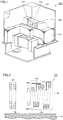
- Fig. 1 is a perspective view showing a configuration of a stationary induction apparatus according to Embodiment 1 of the present invention.
- Fig. 2 is a partial sectional view of the stationary induction apparatus according to Embodiment 1 of the present invention.
- Fig. 3 is a sectional view of the stationary induction apparatus according to Embodiment 1 of the present invention, showing a portion III of Fig. 2 in enlarged view.
- Fig. 1 shows each component in cutaway view.
- Fig. 2 shows windings and insulating barriers 170 located above cores 110.
- a stationary induction apparatus 100 is a shell-type transformer.
- Stationary induction apparatus 100 includes cores 110, windings (low-voltage windings 120 and a high-voltage winding 130) concentrically wound around the main legs of cores 110, where each of the main legs is a central axis, a tank 140, and insulating barriers 170.
- the axial direction of the winding will be hereinafter referred to as a central axis direction.
- Core 110 is formed of a plurality of layered magnetic steel plates.
- two cuboid-shaped cores 110 each having an opening at its middle portion are disposed to be adjacent to each other.
- the windings (low-voltage windings 120 and high-voltage winding 130) are wound around the adjacent main legs of the two cores 110 so as to pass through the respective openings of the two cores 110.
- High-voltage winding 130 is disposed in the central axis direction so as to be sandwiched between low-voltage windings 120.
- the windings are each formed of a plurality of discal winding layers (discal windings) layered to be arranged in the central axis direction.
- Each of the winding layers is formed of a flat-type electric wire 150 wound in a disc shape.
- Flat-type electric wire 150 includes an electric wire portion 151, which has an approximately rectangular shape in transverse section, and an insulating coating 152, which coats electric wire portion 151.
- low-voltage winding 120 also has a configuration similar to that of high-voltage winding 130.
- winding layers adjacent in the central axis direction are connected to each other by an electric conductor (not shown) at their respective outer peripheral ends or inner peripheral ends to be electrically connected to each other.
- a first winding layer 150a and a second winding layer 150b are connected to each other at their inner peripheral ends
- second winding layer 150b and a third winding layer 150c are connected to each other at their outer peripheral ends
- third winding layer 150c and a fourth winding layer 150d are connected to each other at their inner peripheral ends.
- Tank 140 is filled with an insulating oil that is an insulating medium as well as a cooling medium.
- Cores 110, windings (low-voltage windings 120 and high-voltage winding 130), and insulating barriers 170 are each housed in tank 140 and immersed in the insulating oil.
- Stationary induction apparatus 100 further includes a plurality of annular electrostatic shields 160 disposed adjacent to the respective ends of low-voltage windings 120 and high-voltage winding 130 in the central axis direction.
- Fig. 2 shows only one electrostatic shield 160 adjacent to high-voltage winding 130.
- Insulating barrier 170 is disposed between the outer peripheral ends, which are not connected to each other, of the winding layers adjacent to each other in the central axis direction. In the present embodiment, insulating barrier 170 is disposed between the outer peripheral ends of first winding layer 150a and second winding layer 150b and between the outer peripheral ends of third winding layer 150c and fourth winding layer 150d. A plurality of insulating barriers 170 are disposed between the adjacent winding layers so as to be successively disposed over the entire periphery of the winding.
- Fig. 4 is a side view showing a structure of an insulating barrier of the stationary induction apparatus according to Embodiment 1 of the present invention.
- insulating barrier 170 includes a first extension 171 extending radially outwardly of the winding and partitioning the outer peripheral ends, a second extension 172 bent from an end of first extension 171, extending toward one side in the central axis direction, and covering at least a part of one outer peripheral end of the outer peripheral ends, a third extension 173 bent from an end of second extension 172 and extending radially outwardly of the winding, and a fourth extension 174 bent from an end of third extension 173, extending toward the other side in the central axis direction, and covering at least a part of the other outer peripheral end of the outer peripheral ends.
- Fourth extension 174 faces second extension 172 with a spacing D therebetween.
- First extension 171 is inserted between a portion of first winding layer 150a, which is close to the outer periphery, and a portion of second winding layer 150b, which is close to the outer periphery.
- Second extension 172 is bent or curved at the extreme end of first extension 171 and extends toward the outer peripheral end of second winding layer 150b in the central axis direction. Second extension 172 covers at least a part of the outer peripheral end of second winding layer 150b.
- first extension 171 and second extension 172 are approximately perpendicular to each other. The extreme end of second extension 172 reaches above one end in the central axis direction at the outer peripheral end of second winding layer 150b.
- Third extension 173 is bent or curved at the extreme end of second extension 172 and extends radially outwardly of the winding.
- third extension 173 has a flat shape.
- Second extension 172 and third extension 173 are approximately perpendicular to each other.
- third extension 173 may have a semicircular cylindrical shape convexly projecting toward one side in the central axis direction.
- Fourth extension 174 is bent or curved at the extreme end of third extension 173 and extends toward the outer peripheral end of first winding layer 150a in the central axis direction. Fourth extension 174 covers at least a part of the outer peripheral end of first winding layer 150a.
- third extension 173 and fourth extension 174 are approximately perpendicular to each other. The extreme end of fourth extension 174 reaches above the other end in the central axis direction at the outer peripheral end of first winding layer 150a.
- Second extension 172 and fourth extension 174 may extend in the directions opposite to the above directions. Specifically, second extension 172 may extend toward the outer peripheral end of first winding layer 150a in the central axis direction and cover at least a part of the outer peripheral end of first winding layer 150a, and fourth extension 174 may extend toward the outer peripheral end of second winding layer 150b in the central axis direction and cover at least a part of the outer peripheral end of second winding layer 150b.
- Fig. 5 is a side view showing the shape of an insulating plate forming the insulating barrier of the stationary induction apparatus according to Embodiment 1 of the present invention.
- insulating barrier 170 is formed of one insulating plate 10.
- insulating plate 10 is a pressboard.
- a first notch na which is located at a boundary between first extension 171 and second extension 172.
- a second notch nb On the other main surface of insulating plate 10 are provided a second notch nb, which is located at a boundary between second extension 172 and third extension 173, and a third notch nc, which is located at a boundary between third extension 173 and fourth extension 174.
- First notch na, second notch nb, and third notch nc are each provided having a V-shape in side view.
- Fig. 6 is a side view of the insulating barrier of the stationary induction apparatus according to Embodiment 1 of the present invention, which is bent at the first notch. As shown in Fig. 6 , insulating plate 10 is bent such that first notch na is located inwardly. With the inside surfaces of first notch na being in contact with each other, first extension 171 and second extension 172 are approximately perpendicular to each other.
- Fig. 7 is a side view of the insulating barrier of the stationary induction apparatus according to Embodiment 1 of the present invention, which is bent at the second notch. As shown in Fig. 7 , insulating plate 10 is bent such that second notch nb is located inwardly. With the inside surfaces of second notch nb being in contact with each other, second extension 172 and third extension 173 are approximately perpendicular to each other.
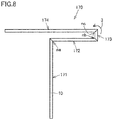
- Fig. 8 is a side view of the insulating barrier of the stationary induction apparatus according to Embodiment 1 of the present invention, which is bent at the third notch. As shown in Fig. 8 , insulating plate 10 is bent such that third notch nc is located inwardly. With the inside surfaces of third notch nc being in contact with each other, third extension 173 and fourth extension 174 are approximately perpendicular to each other.
- an insulating barrier 170 can be formed by bending one insulating plate 10.
- the sequence of bending one insulating plate 10 is not limited to the above, and one insulating plate 10 may be bent in the sequence of third notch nc, second notch nb, and first notch na.
- an insulating barrier 170 may be formed by integrally shaping an insulating resin such as polypropylene, not limited to the formation by bending one insulating plate 10.
- a potential difference Va is generated between the outer peripheral ends of first winding layer 150a and second winding layer 150b, and a potential difference Vb is generated between the outer peripheral ends of third winding layer 150c and fourth winding layer 150d, in the winding.
- Vb reaches an adjacent winding layer, a dielectric breakdown occurs in stationary induction apparatus 100.
- second extension 172 extends toward the outer peripheral end of second winding layer 150b in the central axis direction and covers at least a part of the outer peripheral end of second winding layer 150b
- fourth extension 174 extends toward the outer peripheral end of first winding layer 150a in the central axis direction and covers at least a part of the outer peripheral end of first winding layer 150a
- first extension 171 and third extension 173 partition the outer peripheral end of first winding layer 150a and the outer peripheral end of second winding layer 150b in the central axis direction.
- Insulating barrier 170 formed of one insulating plate 10 can partition the outer peripheral end of first winding layer 150a and the outer peripheral end of second winding layer 150b while covering both of these ends. In addition, the creepage distance between the outer peripheral end of first winding layer 150a and the outer peripheral end of second winding layer 150b can be increased.
- an electric discharge generated in the vicinity of the outer peripheral end of first winding layer 150a can be prevented from progressing toward the outer peripheral end of second winding layer 150b.
- an electric discharge generated in the vicinity of the outer peripheral end of second winding layer 150b can be prevented from progressing toward the outer peripheral end of first winding layer 150a.
- second extension 172 extends toward the outer peripheral end of fourth winding layer 150d in the central axis direction and covers at least a part of the outer peripheral end of fourth winding layer 150d
- fourth extension 174 extends toward the outer peripheral end of third winding layer 150c in the central axis direction and covers at least a part of the outer peripheral end of third winding layer 150c
- first extension 171 and third extension 173 partition the outer peripheral end of third winding layer 150c and the outer peripheral end of fourth winding layer 150d in the central axis direction.
- Insulating barrier 170 formed of one insulating plate 10 can partition the outer peripheral end of third winding layer 150c and the outer peripheral end of fourth winding layer 150d while covering both of these ends. In addition, the creepage distance between the outer peripheral end of third winding layer 150c and the outer peripheral end of fourth winding layer 150d can be increased.
- an electric discharge generated in the vicinity of the outer peripheral end of third winding layer 150c can be prevented from progressing toward the outer peripheral end of fourth winding layer 150d.
- An electric discharge generated in the vicinity of the outer peripheral end of fourth winding layer 150d can be prevented from progressing toward the outer peripheral end of third winding layer 150c.
- insulating barrier 170 can prevent the progression of both of an electric discharge generated from one side in the central axis direction of the winding with respect to insulating barrier 170, and an electric discharge generated from the other side in the central axis direction of the winding with respect to insulating barrier 170.
- the thickness of the portion of insulating barrier 170 which is inserted between the adjacent winding layers is only the thickness of one insulating plate 10. This can prevent the progression of electric discharges generated from the opposite sides of insulating barrier 170 in the central axis direction of the winding while restricting stationary induction apparatus 100 from increasing in size due to the spacing between the winding layers increased by the space for insulating barrier 170.
- fourth extension 174 faces second extension 172 with a spacing D therebetween, an insulating oil is more likely to permeate between second extension 172 and fourth extension 174, and an air bubble is less likely to reside therebetween. The generation of an electric discharge can thus be restricted.
- stationary induction apparatus 100 can prevent, by one insulating barrier 170, the progression of an electric discharge generated from each of one side and the other side in the central axis direction of the winding with respect to insulating barrier 170.
- the stationary induction apparatus 100 can also restrict the generation of an electric discharge due to a remaining air bubble to have stably improved insulating performance.
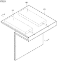
- FIG. 9 is a perspective view showing a structure of an insulating barrier of a stationary induction apparatus according to a modification of Embodiment 1 of the present invention.
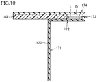
- Fig. 10 is a sectional view of the insulating barrier of Fig. 9 , seen from the direction indicated by the arrow X-X.
- an insulating barrier 170 of the stationary induction apparatus further includes an insulating spacer 180 that is fixed to each of the surface of second extension 172 that faces a fourth extension 174 and the surface of fourth extension 174 that faces second extension 172, and extends in the central axis direction.
- two insulating spacers 180 are provided so as to be arranged with a spacing therebetween.
- insulating spacer 180 has a cuboid outside shape and has a thickness D.
- the outside shape of insulating spacer 180 is not limited to a cuboid shape and may be, for example, a triangular prism shape.
- Insulating spacer 180 is formed of, for example, polypropylene or pressboard.
- One main surface of insulating spacer 180 and second extension 172 are fixed to each other with an adhesive.
- the other main surface of insulating spacer 180 and fourth extension 174 are fixed to each other with an adhesive. Spacing D between second extension 172 and fourth extension 174 can be stably maintained for a long period of time by fixing second extension 172 and fourth extension 174 to each other with insulating spacer 180 therebetween as described above.
- a clearance having a length L is left between a third extension 173 and the end of insulating spacer 180 which faces third extension 173.
- This clearance serves as a flow path for an insulating oil, and accordingly, the insulating oil is more likely to permeate between second extension 172 and fourth extension 174, and an air bubble is less likely to reside therebetween. This stably restricts the generation of an electric discharge due to a residing air bubble.
- FIG. 11 is a sectional view of the stationary induction apparatus according to Embodiment 2 of the present invention.
- Fig. 11 shows the same portion as that of Fig. 3 .
- an insulating barrier 270 of the stationary induction apparatus according to Embodiment 2 of the present invention is disposed between the outer peripheral ends, which are not connected to each other, of the winding layers adjacent in the central axis direction.
- insulating barrier 270 is disposed between the outer peripheral ends of a first winding layer 150a and a second winding layer 150b and between the outer peripheral ends of a third winding layer 150c and a fourth winding layer 150d.
- a plurality of insulating barriers 270 are disposed so as to be successively disposed over the entire periphery of the winding.
- Insulating barrier 270 includes a first extension 271 extending radially outwardly of the winding and partitioning the outer peripheral ends, a second extension 272 bent from an end of first extension 271, extending toward one side in the central axis direction, and covering at least a part of one outer peripheral end of the outer peripheral ends, a third extension 273 bent from an end of second extension 272 and extending radially outwardly of the winding, and a fourth extension 274 bent from an end of third extension 273, extending toward the other side in the central axis direction, and covering at least a part of the other outer peripheral end of the outer peripheral ends.
- Fourth extension 274 faces second extension 272 with a spacing D therebetween.
- Insulating barrier 270 further includes a fifth extension 275 bent from an end of fourth extension 274 and extending radially outwardly of the winding and a sixth extension 276 bent from an end of fifth extension 275, extending toward the one side in the central axis direction, and covering at least a part of the one outer peripheral end.
- Sixth extension 276 faces fourth extension 274 with spacing D therebetween.
- First extension 271 is inserted between a portion of first winding layer 150a, which is close to the outer periphery, and a portion of second winding layer 150b, which is close to the outer periphery.
- Second extension 272 is bent or curved at the extreme end of first extension 271 and extends toward the outer peripheral end of second winding layer 150b in the central axis direction. Second extension 272 covers at least a part of the outer peripheral end of second winding layer 150b.
- first extension 271 and second extension 272 are approximately perpendicular to each other. The extreme end of second extension 272 reaches above the other end in the central axis direction at the outer peripheral end of second winding layer 150b.
- Third extension 273 is bent or curved at the extreme end of second extension 272 and extends radially outwardly of the winding.
- third extension 273 has a flat shape.
- Second extension 272 and third extension 273 are approximately perpendicular to each other.
- third extension 273 may have a semicircular cylindrical shape convexly projecting toward the one side in the central axis direction.
- Fourth extension 274 is bent or curved at the extreme end of third extension 273 and extends toward the outer peripheral end of first winding layer 150a in the central axis direction. Fourth extension 274 covers at least a part of the outer peripheral end of first winding layer 150a.
- third extension 273 and fourth extension 274 are approximately perpendicular to each other. The extreme end of fourth extension 274 reaches above the other end in the central axis direction at the outer peripheral end of first winding layer 150a.
- Fifth extension 275 is bent or curved at the extreme end of fourth extension 274 and extends radially outwardly of the winding.
- fifth extension 275 has a flat shape.
- Fourth extension 274 and fifth extension 275 are approximately perpendicular to each other.
- fifth extension 275 may have a semicircular cylindrical shape convexly projecting toward the other side in the central axis direction.
- Sixth extension 276 is bent or curved at the extreme end of fifth extension 275 and extends toward the outer peripheral end of second winding layer 150b in the central axis direction.
- the distal end of sixth extension 276 is located at the one side in the central axis direction with respect to third extension 273.
- Sixth extension 276 covers at least a part of the outer peripheral end of second winding layer 150b.
- fifth extension 275 and sixth extension 276 are approximately perpendicular to each other. The extreme end of sixth extension 276 reaches above one end in the central axis direction at the outer peripheral end of second winding layer 150b.
- Insulating barrier 270 is formed of one insulating plate.
- the insulating plate is a pressboard.
- Insulating barrier 270 is formed by bending one insulating plate.
- a potential difference Va is generated between the outer peripheral ends of first winding layer 150a and second winding layer 150b, and a potential difference Vb is generated between the outer peripheral ends of third winding layer 150c and fourth winding layer 150d, in the winding.
- Vb reaches an adjacent winding layer, a dielectric breakdown occurs in the stationary induction apparatus.
- second extension 272 and sixth extension 276 extend toward the outer peripheral end of second winding layer 150b in the central axis direction and cover at least a part of the outer peripheral end of second winding layer 150b
- fourth extension 274 extends toward the outer peripheral end of first winding layer 150a in the central axis direction and covers at least a part of the outer peripheral end of first winding layer 150a
- first extension 271, third extension 173, and fifth extension 275 partition the outer peripheral end of first winding layer 150a and the outer peripheral end of second winding layer 150b in the central axis direction.
- Insulating barrier 270 formed of one insulating plate can partition the outer peripheral end of first winding layer 150a and the outer peripheral end of second winding layer 150b while covering both of these ends.
- the creepage distance between the outer peripheral end of first winding layer 150a and the outer peripheral end of second winding layer 150b can be increased further.
- an electric discharge generated in the vicinity of the outer peripheral end of first winding layer 150a can be prevented from progressing toward the outer peripheral end of second winding layer 150b.
- An electric discharge generated in the vicinity of the outer peripheral end of second winding layer 150b can be prevented from progressing toward the outer peripheral end of first winding layer 150a.
- second extension 272 and sixth extension 276 extend toward the outer peripheral end of fourth winding layer 150d in the central axis direction and cover at least a part of the outer peripheral end of fourth winding layer 150d
- fourth extension 274 extends toward the outer peripheral end of third winding layer 150c in the central axis direction and covers at least a part of the outer peripheral end of third winding layer 150c
- first extension 271, third extension 273, and fifth extension 275 partition the outer peripheral end of third winding layer 150c and the outer peripheral end of fourth winding layer 150d in the central axis direction.
- Insulating barrier 270 formed of one insulating plate can partition the outer peripheral end of third winding layer 150c and the outer peripheral end of fourth winding layer 150d while covering both of these ends.
- the creepage distance between the outer peripheral end of third winding layer 150c and the outer peripheral end of fourth winding layer 150d can be increased further.
- an electric discharge generated in the vicinity of the outer peripheral end of third winding layer 150c can be prevented from progressing toward the outer peripheral end of fourth winding layer 150d.
- An electric discharge generated in the vicinity of the outer peripheral end of fourth winding layer 150d can be prevented from progressing toward the outer peripheral end of third winding layer 150c.
- insulating barrier 270 can prevent the progression of both of an electric discharge generated from one side in the central axis direction of the winding with respect to insulating barrier 270 and an electric discharge generated from the other side in the central axis direction of the winding with respect to insulating barrier 270.
- the thickness of the portion of insulating barrier 270 which is inserted between the adjacent windings is only the thickness of one insulating plate. This can prevent the progression of electric discharges generated from the opposite sides of insulating barrier 270 in the central axis direction of the winding while restricting the stationary induction apparatus from increasing in size due to the spacing between the adjacent winding layers which is increased by the space for insulating barrier 270.
- fourth extension 274 faces second extension 272 with a spacing D therebetween, the insulating oil is more likely to permeate between second extension 272 and fourth extension 274, and an air bubble is less likely to reside therebetween. The generation of an electric discharge due to a remaining air bubble can thus be restricted.
- sixth extension 276 faces fourth extension 274 with spacing D therebetween, the insulating oil is more likely to permeate between fourth extension 274 and sixth extension 276, and an air bubble is less likely to reside therebetween. The generation of an electric discharge due to a remaining air bubble can thus be restricted.
- the stationary induction apparatus can prevent, by one insulating barrier 270, the progression of an electric discharge generated from each of one side and the other side in the central axis direction of the winding with respect to insulating barrier 270.
- the stationary induction apparatus can also restrict the generation of an electric discharge due to a remaining air bubble to have stably improved insulating performance.
- 10 insulating plate; 100: stationary induction apparatus; 110: core; 120: low-voltage winding; 130: high-voltage winding; 140: tank; 150: flat-type electric wire; 150a: first winding layer; 150b: second winding layer; 150c: third winding layer; 150d: fourth winding layer; 151: electric wire portion; 152: insulating coating; 160: electrostatic shield; 170, 270: insulating barrier; 171, 271: first extension; 172, 272: second extension; 173, 273: third extension; 174, 274: fourth extension; 180: insulating spacer; 275: fifth extension; 276: sixth extension; na: first notch; nb: second notch; nc: third notch.
Landscapes
- Engineering & Computer Science (AREA)
- Power Engineering (AREA)
- Insulating Of Coils (AREA)
Claims (5)
- Stationäre Induktionsvorrichtung, umfassend:eine Wicklung (120, 130), die aus einer Vielzahl von Wicklungsschichten gebildet ist, welche in einer Mittelachsenrichtung angeordnet sind;eine isolierende Barriere (170, 270), die zwischen zueinander in der Mittelachsenrichtung benachbarten äußeren Umfangsenden der Wicklungsschichten , angeordnet ist, wobei die äußeren Umfangsenden nicht miteinander verbunden sind; undein Isolieröl, in das sowohl die Wicklung (120, 130) als auch die isolierende Barriere (170, 270) eingetaucht sind,wobei die isolierende Barriere (170, 270) aufweist:einen ersten Fortsatz (171, 271), der sich von der Wicklung (120, 130) radial nach außen erstreckt und die äußeren Umfangenden unterteilt,einen zweiten Fortsatz (172, 272), der ausgehend von einem Ende des ersten Fortsatzes (171, 271) gebogen ist, sich zu einer Seite in der Mittelachsenrichtung erstreckt und zumindest einen Teil eines äußeren Umfangsendes der äußeren Umfangsenden abdeckt, gekennzeichnet durcheinen dritten Fortsatz (173, 273), der ausgehend von einem Ende des zweiten Fortsatzes (172, 272) gebogen ist und sich von der Wicklung (120, 130) radial nach außen erstreckt, undeinen vierten Fortsatz (174, 274), der ausgehend von einem Ende des dritten Fortsatzes (173, 273) gebogen ist, sich zur anderen Seite in der Mittelachsenrichtung erstreckt und zumindest einen Teil des anderen äußeren Umfangsendes der äußeren Umfangsenden bedeckt,wobei der vierte Fortsatz (174, 274) dem zweiten Fortsatz (172, 272) mit einem Abstand dazwischen zugewandt ist.
- Stationäre Induktionsvorrichtung nach Anspruch 1, wobei
die isolierende Barriere (170, 270) durch Biegen einer isolierenden Platte (10) an ersten, zweiten und dritten Einkerbungen (na, nb, nc) gebildet wird,
wobei eine Hauptfläche der isolierenden Platte (10) die erste Einkerbung (na) an einer Grenze zwischen dem ersten Fortsatz (171, 271) und dem zweiten Fortsatz (172, 272) aufweist, und
die andere Hauptfläche der isolierenden Platte (10)
die zweite Einkerbung (nb) an einer Grenze zwischen dem zweiten Fortsatz (172, 272) und dem dritten Fortsatz (173, 273) aufweist, und
wobei sich die dritte Einkerbung (nc) an einer Grenze zwischen dem dritten Fortsatz (173, 273) und dem vierten Fortsatz (174, 274) befindet. - Stationäre Induktionsvorrichtung nach Anspruch 1 oder 2, wobei
die isolierende Barriere (170) ferner einen isolierenden Abstandshalter (180) aufweist, der an jeder von einer Oberfläche des zweiten Fortsatzes (172), welche dem vierten Fortsatz (174) zugewandt ist, und einer Oberfläche des vierten Fortsatzes (174), welche dem zweiten Fortsatz (172) zugewandt ist, fixiert ist, wobei sich der isolierende Abstandshalter (180) in der Mittelachsenrichtung erstreckt, und
ein Freiraumraum zwischen dem dritten Fortsatz (173) und einem dem dritten Fortsatz (173) zugewandten Ende des isolierenden Abstandshalters (180) verbleibt. - Stationäre Induktionsvorrichtung nach einem der Ansprüche 1 bis 3, wobei die isolierende Barriere (270) ferner aufweist:einen fünften Fortsatz (275), der ausgehend von einem Ende des vierten Fortsatzes (274) gebogen ist und sich von der Wicklung (120, 130) radial nach außen erstreckt, undeinen sechsten Fortsatz (276), der ausgehend von einem Ende des fünften Fortsatzes (275) gebogen ist, sich zu der einen Seite in der Mittelachsenrichtung erstreckt und zumindest einen Teil des einen äußeren Umfangsendes bedeckt,wobei der sechste Fortsatz (276) dem vierten Fortsatz (274) mit einem Abstand dazwischen zugewandt ist, undwobei sich ein distales Ende des sechsten Fortsatzes (276) auf der einen Seite in Mittelachsenrichtung in Bezug auf den dritten Fortsatz (273) befindet.
- Stationäre Induktionsvorrichtung nach Anspruch 2, wobei die isolierende Platte (10) eine Pressspanplatte umfasst.
Applications Claiming Priority (1)
| Application Number | Priority Date | Filing Date | Title |
|---|---|---|---|
| PCT/JP2015/072629 WO2017026028A1 (ja) | 2015-08-10 | 2015-08-10 | 静止誘導機器 |
Publications (3)
| Publication Number | Publication Date |
|---|---|
| EP3327737A1 EP3327737A1 (de) | 2018-05-30 |
| EP3327737A4 EP3327737A4 (de) | 2019-03-06 |
| EP3327737B1 true EP3327737B1 (de) | 2020-01-01 |
Family
ID=55523938
Family Applications (1)
| Application Number | Title | Priority Date | Filing Date |
|---|---|---|---|
| EP15900982.8A Active EP3327737B1 (de) | 2015-08-10 | 2015-08-10 | Stationäre induktionsvorrichtung |
Country Status (4)
| Country | Link |
|---|---|
| US (1) | US10714258B2 (de) |
| EP (1) | EP3327737B1 (de) |
| JP (1) | JP5885898B1 (de) |
| WO (1) | WO2017026028A1 (de) |
Families Citing this family (1)
| Publication number | Priority date | Publication date | Assignee | Title |
|---|---|---|---|---|
| KR102001940B1 (ko) * | 2018-02-05 | 2019-07-22 | 효성중공업 주식회사 | 변압기용 소음저감장치 |
Family Cites Families (19)
| Publication number | Priority date | Publication date | Assignee | Title |
|---|---|---|---|---|
| US2246159A (en) * | 1938-12-01 | 1941-06-17 | Gen Electric | Electrical coil |
| JPS42251Y1 (de) * | 1965-05-12 | 1967-01-10 | ||
| US3376530A (en) * | 1966-04-27 | 1968-04-02 | Westinghouse Electric Corp | Axially spaced transformer pancake coils having static plate |
| US3602857A (en) * | 1970-07-10 | 1971-08-31 | Westinghouse Electric Corp | Shielded winding with cooling ducts |
| JPS5350819Y2 (de) * | 1973-02-01 | 1978-12-05 | ||
| JPS5343646B2 (de) * | 1974-12-23 | 1978-11-21 | ||
| JPS5534669U (de) * | 1978-08-30 | 1980-03-06 | ||
| JPS6060705A (ja) * | 1983-09-14 | 1985-04-08 | Toshiba Corp | 箔巻変圧器 |
| JPS6113904U (ja) | 1984-06-30 | 1986-01-27 | 東芝テック株式会社 | 電磁コイル |
| JPS62168620U (de) * | 1986-04-16 | 1987-10-26 | ||
| JPS63245915A (ja) | 1987-03-31 | 1988-10-13 | Toshiba Corp | 巻線体 |
| GB2331853A (en) * | 1997-11-28 | 1999-06-02 | Asea Brown Boveri | Transformer |
| JP2000277353A (ja) * | 1999-03-26 | 2000-10-06 | Takaoka Electric Mfg Co Ltd | 変圧器巻線 |
| JP2001351820A (ja) * | 2000-06-07 | 2001-12-21 | Mitsubishi Electric Corp | 電気機器 |
| DE10117847C1 (de) * | 2001-04-04 | 2003-02-06 | Siemens Ag | Transformator mit forcierter Flüssigkeitskühlung |
| CN101136281B (zh) * | 2006-08-28 | 2011-10-26 | Abb技术有限公司 | 具有屏蔽环的高压变压器、屏蔽环及屏蔽环的制造方法 |
| US8547193B2 (en) * | 2009-10-21 | 2013-10-01 | Mitsubishi Electric Corporation | Stationary induction apparatus |
| EP2636049A1 (de) * | 2010-11-03 | 2013-09-11 | ABB Technology AG | Vorhersage der restlebensdauer eines transformators |
| EP2584573A1 (de) * | 2011-10-18 | 2013-04-24 | ABB Technology AG | Hochspannungsisolierungssystem |
-
2015
- 2015-08-10 EP EP15900982.8A patent/EP3327737B1/de active Active
- 2015-08-10 US US15/737,391 patent/US10714258B2/en active Active
- 2015-08-10 WO PCT/JP2015/072629 patent/WO2017026028A1/ja not_active Ceased
- 2015-08-10 JP JP2015554380A patent/JP5885898B1/ja active Active
Non-Patent Citations (1)
| Title |
|---|
| None * |
Also Published As
| Publication number | Publication date |
|---|---|
| JP5885898B1 (ja) | 2016-03-16 |
| EP3327737A1 (de) | 2018-05-30 |
| JPWO2017026028A1 (ja) | 2017-08-10 |
| US10714258B2 (en) | 2020-07-14 |
| US20180166209A1 (en) | 2018-06-14 |
| EP3327737A4 (de) | 2019-03-06 |
| WO2017026028A1 (ja) | 2017-02-16 |
Similar Documents
| Publication | Publication Date | Title |
|---|---|---|
| EP2586044B2 (de) | Spule mit elektrischer Abschrimung und Transformator mit solcher Anordnung | |
| US11217377B2 (en) | Low inter-winding capacitance coil form | |
| KR101845823B1 (ko) | 고전압 트랜스포머용 2차보빈 및 이를 이용한 고전압 트랜스포머 | |
| US11355278B2 (en) | Insulating transformers | |
| US10714258B2 (en) | Stationary induction apparatus | |
| US10090095B2 (en) | Stationary induction electrical apparatus | |
| JP4794999B2 (ja) | 耐雷強化型低圧用絶縁変圧器 | |
| US20160111206A1 (en) | Transformer | |
| JP7368956B2 (ja) | 変成器及びボビン | |
| JP6552779B1 (ja) | 静止誘導器 | |
| JP6656187B2 (ja) | 静止誘導器 | |
| US2368506A (en) | Electric apparatus and winding therefor | |
| JP7170503B2 (ja) | ガス絶縁変圧器 | |
| JP2013055279A (ja) | 静止誘導電器 | |
| US9449755B2 (en) | Arrangement having at least two coils which are arranged axially one above the other on a common core limb | |
| KR102882973B1 (ko) | 변압기 | |
| KR102135202B1 (ko) | 변압기 | |
| KR102742985B1 (ko) | 전자기 유도 장치의 전기 권선을 제조하는 방법 및 도체 구조 | |
| CN101572173B (zh) | 绕线管结构及具有该绕线管的变压器 | |
| JP7414684B2 (ja) | ガス絶縁変圧器 | |
| JP2022070768A (ja) | モ-ルド変圧器 | |
| JP2010219338A (ja) | 静止誘導機器 | |
| JP2019179849A (ja) | 静止誘導機器 | |
| JPS63245915A (ja) | 巻線体 |
Legal Events
| Date | Code | Title | Description |
|---|---|---|---|
| STAA | Information on the status of an ep patent application or granted ep patent |
Free format text: STATUS: THE INTERNATIONAL PUBLICATION HAS BEEN MADE |
|
| PUAI | Public reference made under article 153(3) epc to a published international application that has entered the european phase |
Free format text: ORIGINAL CODE: 0009012 |
|
| STAA | Information on the status of an ep patent application or granted ep patent |
Free format text: STATUS: REQUEST FOR EXAMINATION WAS MADE |
|
| 17P | Request for examination filed |
Effective date: 20180111 |
|
| AK | Designated contracting states |
Kind code of ref document: A1 Designated state(s): AL AT BE BG CH CY CZ DE DK EE ES FI FR GB GR HR HU IE IS IT LI LT LU LV MC MK MT NL NO PL PT RO RS SE SI SK SM TR |
|
| AX | Request for extension of the european patent |
Extension state: BA ME |
|
| DAV | Request for validation of the european patent (deleted) | ||
| DAX | Request for extension of the european patent (deleted) | ||
| REG | Reference to a national code |
Ref country code: DE Ref legal event code: R079 Ref document number: 602015044985 Country of ref document: DE Free format text: PREVIOUS MAIN CLASS: H01F0027320000 Ipc: H01F0027120000 |
|
| A4 | Supplementary search report drawn up and despatched |
Effective date: 20190204 |
|
| RIC1 | Information provided on ipc code assigned before grant |
Ipc: H01F 27/32 20060101ALI20190129BHEP Ipc: H01F 27/12 20060101AFI20190129BHEP Ipc: H01F 27/36 20060101ALI20190129BHEP Ipc: H01F 27/28 20060101ALI20190129BHEP |
|
| GRAP | Despatch of communication of intention to grant a patent |
Free format text: ORIGINAL CODE: EPIDOSNIGR1 |
|
| STAA | Information on the status of an ep patent application or granted ep patent |
Free format text: STATUS: GRANT OF PATENT IS INTENDED |
|
| INTG | Intention to grant announced |
Effective date: 20190723 |
|
| GRAS | Grant fee paid |
Free format text: ORIGINAL CODE: EPIDOSNIGR3 |
|
| GRAA | (expected) grant |
Free format text: ORIGINAL CODE: 0009210 |
|
| STAA | Information on the status of an ep patent application or granted ep patent |
Free format text: STATUS: THE PATENT HAS BEEN GRANTED |
|
| AK | Designated contracting states |
Kind code of ref document: B1 Designated state(s): AL AT BE BG CH CY CZ DE DK EE ES FI FR GB GR HR HU IE IS IT LI LT LU LV MC MK MT NL NO PL PT RO RS SE SI SK SM TR |
|
| REG | Reference to a national code |
Ref country code: GB Ref legal event code: FG4D |
|
| REG | Reference to a national code |
Ref country code: CH Ref legal event code: EP Ref country code: AT Ref legal event code: REF Ref document number: 1220828 Country of ref document: AT Kind code of ref document: T Effective date: 20200115 |
|
| REG | Reference to a national code |
Ref country code: IE Ref legal event code: FG4D |
|
| REG | Reference to a national code |
Ref country code: DE Ref legal event code: R096 Ref document number: 602015044985 Country of ref document: DE |
|
| REG | Reference to a national code |
Ref country code: NL Ref legal event code: MP Effective date: 20200101 |
|
| REG | Reference to a national code |
Ref country code: LT Ref legal event code: MG4D |
|
| PG25 | Lapsed in a contracting state [announced via postgrant information from national office to epo] |
Ref country code: CZ Free format text: LAPSE BECAUSE OF FAILURE TO SUBMIT A TRANSLATION OF THE DESCRIPTION OR TO PAY THE FEE WITHIN THE PRESCRIBED TIME-LIMIT Effective date: 20200101 Ref country code: PT Free format text: LAPSE BECAUSE OF FAILURE TO SUBMIT A TRANSLATION OF THE DESCRIPTION OR TO PAY THE FEE WITHIN THE PRESCRIBED TIME-LIMIT Effective date: 20200527 Ref country code: NO Free format text: LAPSE BECAUSE OF FAILURE TO SUBMIT A TRANSLATION OF THE DESCRIPTION OR TO PAY THE FEE WITHIN THE PRESCRIBED TIME-LIMIT Effective date: 20200401 Ref country code: LT Free format text: LAPSE BECAUSE OF FAILURE TO SUBMIT A TRANSLATION OF THE DESCRIPTION OR TO PAY THE FEE WITHIN THE PRESCRIBED TIME-LIMIT Effective date: 20200101 Ref country code: RS Free format text: LAPSE BECAUSE OF FAILURE TO SUBMIT A TRANSLATION OF THE DESCRIPTION OR TO PAY THE FEE WITHIN THE PRESCRIBED TIME-LIMIT Effective date: 20200101 Ref country code: NL Free format text: LAPSE BECAUSE OF FAILURE TO SUBMIT A TRANSLATION OF THE DESCRIPTION OR TO PAY THE FEE WITHIN THE PRESCRIBED TIME-LIMIT Effective date: 20200101 Ref country code: FI Free format text: LAPSE BECAUSE OF FAILURE TO SUBMIT A TRANSLATION OF THE DESCRIPTION OR TO PAY THE FEE WITHIN THE PRESCRIBED TIME-LIMIT Effective date: 20200101 |
|
| PG25 | Lapsed in a contracting state [announced via postgrant information from national office to epo] |
Ref country code: IS Free format text: LAPSE BECAUSE OF FAILURE TO SUBMIT A TRANSLATION OF THE DESCRIPTION OR TO PAY THE FEE WITHIN THE PRESCRIBED TIME-LIMIT Effective date: 20200501 Ref country code: GR Free format text: LAPSE BECAUSE OF FAILURE TO SUBMIT A TRANSLATION OF THE DESCRIPTION OR TO PAY THE FEE WITHIN THE PRESCRIBED TIME-LIMIT Effective date: 20200402 Ref country code: HR Free format text: LAPSE BECAUSE OF FAILURE TO SUBMIT A TRANSLATION OF THE DESCRIPTION OR TO PAY THE FEE WITHIN THE PRESCRIBED TIME-LIMIT Effective date: 20200101 Ref country code: SE Free format text: LAPSE BECAUSE OF FAILURE TO SUBMIT A TRANSLATION OF THE DESCRIPTION OR TO PAY THE FEE WITHIN THE PRESCRIBED TIME-LIMIT Effective date: 20200101 Ref country code: LV Free format text: LAPSE BECAUSE OF FAILURE TO SUBMIT A TRANSLATION OF THE DESCRIPTION OR TO PAY THE FEE WITHIN THE PRESCRIBED TIME-LIMIT Effective date: 20200101 Ref country code: BG Free format text: LAPSE BECAUSE OF FAILURE TO SUBMIT A TRANSLATION OF THE DESCRIPTION OR TO PAY THE FEE WITHIN THE PRESCRIBED TIME-LIMIT Effective date: 20200401 |
|
| REG | Reference to a national code |
Ref country code: DE Ref legal event code: R097 Ref document number: 602015044985 Country of ref document: DE |
|
| PG25 | Lapsed in a contracting state [announced via postgrant information from national office to epo] |
Ref country code: ES Free format text: LAPSE BECAUSE OF FAILURE TO SUBMIT A TRANSLATION OF THE DESCRIPTION OR TO PAY THE FEE WITHIN THE PRESCRIBED TIME-LIMIT Effective date: 20200101 Ref country code: DK Free format text: LAPSE BECAUSE OF FAILURE TO SUBMIT A TRANSLATION OF THE DESCRIPTION OR TO PAY THE FEE WITHIN THE PRESCRIBED TIME-LIMIT Effective date: 20200101 Ref country code: EE Free format text: LAPSE BECAUSE OF FAILURE TO SUBMIT A TRANSLATION OF THE DESCRIPTION OR TO PAY THE FEE WITHIN THE PRESCRIBED TIME-LIMIT Effective date: 20200101 Ref country code: RO Free format text: LAPSE BECAUSE OF FAILURE TO SUBMIT A TRANSLATION OF THE DESCRIPTION OR TO PAY THE FEE WITHIN THE PRESCRIBED TIME-LIMIT Effective date: 20200101 Ref country code: SK Free format text: LAPSE BECAUSE OF FAILURE TO SUBMIT A TRANSLATION OF THE DESCRIPTION OR TO PAY THE FEE WITHIN THE PRESCRIBED TIME-LIMIT Effective date: 20200101 Ref country code: SM Free format text: LAPSE BECAUSE OF FAILURE TO SUBMIT A TRANSLATION OF THE DESCRIPTION OR TO PAY THE FEE WITHIN THE PRESCRIBED TIME-LIMIT Effective date: 20200101 |
|
| PLBE | No opposition filed within time limit |
Free format text: ORIGINAL CODE: 0009261 |
|
| STAA | Information on the status of an ep patent application or granted ep patent |
Free format text: STATUS: NO OPPOSITION FILED WITHIN TIME LIMIT |
|
| REG | Reference to a national code |
Ref country code: AT Ref legal event code: MK05 Ref document number: 1220828 Country of ref document: AT Kind code of ref document: T Effective date: 20200101 |
|
| 26N | No opposition filed |
Effective date: 20201002 |
|
| PG25 | Lapsed in a contracting state [announced via postgrant information from national office to epo] |
Ref country code: IT Free format text: LAPSE BECAUSE OF FAILURE TO SUBMIT A TRANSLATION OF THE DESCRIPTION OR TO PAY THE FEE WITHIN THE PRESCRIBED TIME-LIMIT Effective date: 20200101 Ref country code: AT Free format text: LAPSE BECAUSE OF FAILURE TO SUBMIT A TRANSLATION OF THE DESCRIPTION OR TO PAY THE FEE WITHIN THE PRESCRIBED TIME-LIMIT Effective date: 20200101 |
|
| PG25 | Lapsed in a contracting state [announced via postgrant information from national office to epo] |
Ref country code: SI Free format text: LAPSE BECAUSE OF FAILURE TO SUBMIT A TRANSLATION OF THE DESCRIPTION OR TO PAY THE FEE WITHIN THE PRESCRIBED TIME-LIMIT Effective date: 20200101 Ref country code: PL Free format text: LAPSE BECAUSE OF FAILURE TO SUBMIT A TRANSLATION OF THE DESCRIPTION OR TO PAY THE FEE WITHIN THE PRESCRIBED TIME-LIMIT Effective date: 20200101 |
|
| REG | Reference to a national code |
Ref country code: DE Ref legal event code: R119 Ref document number: 602015044985 Country of ref document: DE |
|
| PG25 | Lapsed in a contracting state [announced via postgrant information from national office to epo] |
Ref country code: MC Free format text: LAPSE BECAUSE OF FAILURE TO SUBMIT A TRANSLATION OF THE DESCRIPTION OR TO PAY THE FEE WITHIN THE PRESCRIBED TIME-LIMIT Effective date: 20200101 |
|
| REG | Reference to a national code |
Ref country code: CH Ref legal event code: PL |
|
| GBPC | Gb: european patent ceased through non-payment of renewal fee |
Effective date: 20200810 |
|
| PG25 | Lapsed in a contracting state [announced via postgrant information from national office to epo] |
Ref country code: LU Free format text: LAPSE BECAUSE OF NON-PAYMENT OF DUE FEES Effective date: 20200810 Ref country code: LI Free format text: LAPSE BECAUSE OF NON-PAYMENT OF DUE FEES Effective date: 20200831 Ref country code: CH Free format text: LAPSE BECAUSE OF NON-PAYMENT OF DUE FEES Effective date: 20200831 |
|
| REG | Reference to a national code |
Ref country code: BE Ref legal event code: MM Effective date: 20200831 |
|
| PG25 | Lapsed in a contracting state [announced via postgrant information from national office to epo] |
Ref country code: DE Free format text: LAPSE BECAUSE OF NON-PAYMENT OF DUE FEES Effective date: 20210302 |
|
| PG25 | Lapsed in a contracting state [announced via postgrant information from national office to epo] |
Ref country code: BE Free format text: LAPSE BECAUSE OF NON-PAYMENT OF DUE FEES Effective date: 20200831 Ref country code: GB Free format text: LAPSE BECAUSE OF NON-PAYMENT OF DUE FEES Effective date: 20200810 Ref country code: IE Free format text: LAPSE BECAUSE OF NON-PAYMENT OF DUE FEES Effective date: 20200810 |
|
| PG25 | Lapsed in a contracting state [announced via postgrant information from national office to epo] |
Ref country code: TR Free format text: LAPSE BECAUSE OF FAILURE TO SUBMIT A TRANSLATION OF THE DESCRIPTION OR TO PAY THE FEE WITHIN THE PRESCRIBED TIME-LIMIT Effective date: 20200101 Ref country code: MT Free format text: LAPSE BECAUSE OF FAILURE TO SUBMIT A TRANSLATION OF THE DESCRIPTION OR TO PAY THE FEE WITHIN THE PRESCRIBED TIME-LIMIT Effective date: 20200101 Ref country code: CY Free format text: LAPSE BECAUSE OF FAILURE TO SUBMIT A TRANSLATION OF THE DESCRIPTION OR TO PAY THE FEE WITHIN THE PRESCRIBED TIME-LIMIT Effective date: 20200101 |
|
| PG25 | Lapsed in a contracting state [announced via postgrant information from national office to epo] |
Ref country code: MK Free format text: LAPSE BECAUSE OF FAILURE TO SUBMIT A TRANSLATION OF THE DESCRIPTION OR TO PAY THE FEE WITHIN THE PRESCRIBED TIME-LIMIT Effective date: 20200101 Ref country code: AL Free format text: LAPSE BECAUSE OF FAILURE TO SUBMIT A TRANSLATION OF THE DESCRIPTION OR TO PAY THE FEE WITHIN THE PRESCRIBED TIME-LIMIT Effective date: 20200101 |
|
| P01 | Opt-out of the competence of the unified patent court (upc) registered |
Effective date: 20230512 |
|
| PGFP | Annual fee paid to national office [announced via postgrant information from national office to epo] |
Ref country code: FR Payment date: 20250703 Year of fee payment: 11 |