EP3327475A1 - Connector for optical fibers with lenses - Google Patents
Connector for optical fibers with lenses Download PDFInfo
- Publication number
- EP3327475A1 EP3327475A1 EP16827494.2A EP16827494A EP3327475A1 EP 3327475 A1 EP3327475 A1 EP 3327475A1 EP 16827494 A EP16827494 A EP 16827494A EP 3327475 A1 EP3327475 A1 EP 3327475A1
- Authority
- EP
- European Patent Office
- Prior art keywords
- optical fibers
- lenses
- lens
- ferrules
- central axis
- Prior art date
- Legal status (The legal status is an assumption and is not a legal conclusion. Google has not performed a legal analysis and makes no representation as to the accuracy of the status listed.)
- Ceased
Links
Images


Classifications
-
- G—PHYSICS
- G02—OPTICS
- G02B—OPTICAL ELEMENTS, SYSTEMS OR APPARATUS
- G02B6/00—Light guides; Structural details of arrangements comprising light guides and other optical elements, e.g. couplings
- G02B6/24—Coupling light guides
- G02B6/26—Optical coupling means
- G02B6/32—Optical coupling means having lens focusing means positioned between opposed fibre ends
-
- G—PHYSICS
- G02—OPTICS
- G02B—OPTICAL ELEMENTS, SYSTEMS OR APPARATUS
- G02B6/00—Light guides; Structural details of arrangements comprising light guides and other optical elements, e.g. couplings
- G02B6/24—Coupling light guides
- G02B6/36—Mechanical coupling means
- G02B6/38—Mechanical coupling means having fibre to fibre mating means
- G02B6/3807—Dismountable connectors, i.e. comprising plugs
- G02B6/3833—Details of mounting fibres in ferrules; Assembly methods; Manufacture
- G02B6/3853—Lens inside the ferrule
-
- G—PHYSICS
- G02—OPTICS
- G02B—OPTICAL ELEMENTS, SYSTEMS OR APPARATUS
- G02B6/00—Light guides; Structural details of arrangements comprising light guides and other optical elements, e.g. couplings
- G02B6/24—Coupling light guides
- G02B6/26—Optical coupling means
- G02B6/262—Optical details of coupling light into, or out of, or between fibre ends, e.g. special fibre end shapes or associated optical elements
-
- G—PHYSICS
- G02—OPTICS
- G02B—OPTICAL ELEMENTS, SYSTEMS OR APPARATUS
- G02B6/00—Light guides; Structural details of arrangements comprising light guides and other optical elements, e.g. couplings
- G02B6/24—Coupling light guides
- G02B6/36—Mechanical coupling means
- G02B6/38—Mechanical coupling means having fibre to fibre mating means
- G02B6/3807—Dismountable connectors, i.e. comprising plugs
- G02B6/3873—Connectors using guide surfaces for aligning ferrule ends, e.g. tubes, sleeves, V-grooves, rods, pins, balls
- G02B6/3874—Connectors using guide surfaces for aligning ferrule ends, e.g. tubes, sleeves, V-grooves, rods, pins, balls using tubes, sleeves to align ferrules
-
- G—PHYSICS
- G02—OPTICS
- G02B—OPTICAL ELEMENTS, SYSTEMS OR APPARATUS
- G02B6/00—Light guides; Structural details of arrangements comprising light guides and other optical elements, e.g. couplings
- G02B6/24—Coupling light guides
- G02B6/36—Mechanical coupling means
- G02B6/38—Mechanical coupling means having fibre to fibre mating means
- G02B6/3807—Dismountable connectors, i.e. comprising plugs
- G02B6/3873—Connectors using guide surfaces for aligning ferrule ends, e.g. tubes, sleeves, V-grooves, rods, pins, balls
- G02B6/3882—Connectors using guide surfaces for aligning ferrule ends, e.g. tubes, sleeves, V-grooves, rods, pins, balls using rods, pins or balls to align a pair of ferrule ends
-
- G—PHYSICS
- G02—OPTICS
- G02B—OPTICAL ELEMENTS, SYSTEMS OR APPARATUS
- G02B6/00—Light guides; Structural details of arrangements comprising light guides and other optical elements, e.g. couplings
- G02B6/24—Coupling light guides
- G02B6/36—Mechanical coupling means
- G02B6/38—Mechanical coupling means having fibre to fibre mating means
- G02B6/3807—Dismountable connectors, i.e. comprising plugs
- G02B6/389—Dismountable connectors, i.e. comprising plugs characterised by the method of fastening connecting plugs and sockets, e.g. screw- or nut-lock, snap-in, bayonet type
- G02B6/3893—Push-pull type, e.g. snap-in, push-on
-
- G—PHYSICS
- G02—OPTICS
- G02B—OPTICAL ELEMENTS, SYSTEMS OR APPARATUS
- G02B6/00—Light guides; Structural details of arrangements comprising light guides and other optical elements, e.g. couplings
- G02B6/24—Coupling light guides
- G02B6/36—Mechanical coupling means
- G02B6/38—Mechanical coupling means having fibre to fibre mating means
- G02B6/3807—Dismountable connectors, i.e. comprising plugs
- G02B6/3873—Connectors using guide surfaces for aligning ferrule ends, e.g. tubes, sleeves, V-grooves, rods, pins, balls
- G02B6/3885—Multicore or multichannel optical connectors, i.e. one single ferrule containing more than one fibre, e.g. ribbon type
-
- G—PHYSICS
- G02—OPTICS
- G02B—OPTICAL ELEMENTS, SYSTEMS OR APPARATUS
- G02B6/00—Light guides; Structural details of arrangements comprising light guides and other optical elements, e.g. couplings
- G02B6/24—Coupling light guides
- G02B6/36—Mechanical coupling means
- G02B6/40—Mechanical coupling means having fibre bundle mating means
- G02B6/403—Mechanical coupling means having fibre bundle mating means of the ferrule type, connecting a pair of ferrules
Definitions
- the present invention relates to a connector for optical fibers with lenses which connects optical fibers with lenses together.
- optical fibers in order to prevent reflected return light on an optical fiber end face, it is generally known that the optical fibers having end faces formed into an oblique shape are made to face each other, and it is proposed to position a pair of optical fibers in grooves, the axes of which are displaced from each other, such that the end faces of the optical fibers which face each other are substantially parallel to each other and the emission optical axis of one of the optical fibers coincides with the core center of the other optical fiber (see PTL 1).
- an optical fiber with lens there is known an optical fiber collimator which emits light emitted from an optical fiber as parallel light using a lens, and there is known an optical fiber with GRIN lens which uses a GRIN lens (gradient index lens) as the lens and has the end part of the optical fiber welded to the center of the GRIN lens.
- GRIN lens gradient index lens
- connection between the optical fibers with lenses by coaxially disposing the optical fibers with lenses such that the optical fibers with lenses face each other, light emitted from one of the optical fibers becomes parallel light by one of the lenses, and the parallel light is focused by the other lens and enters the other optical fiber.
- a sufficient interval is provided between lens end faces (see PTL 2 shown below).
- the prevention of the reflected return light is a major task and, in order to achieve this task, it is known that the emission end face of the lens is obliquely formed, and it is known that, in order to connect the optical fibers with lenses having the obliquely inclined emission end faces, the optical fiber with lens is supported by a groove on a board (see PTL 4 shown below).
- connection between the optical fibers with lenses it is possible to reduce the energy density of emitted light by beam expansion by the collimator, and connect the optical fibers with lenses together in a state in which connection end faces are not in contact with each other. With the reduction in energy density, it is possible to avert a phenomenon in which the connection end face and the inside of the fiber are damaged by heat generation caused by concentration of energy on a foreign object and a fiber fuse resulting from the heat generation.
- connection end faces by preventing the connection end faces from coming into contact with each other, optical coupling is allowed even when a small foreign object is present on the connection end face, it is possible to save labor such as cleaning of the connection end face, and it is also possible to avert the occurrence of a dent or a chip of the end face caused by the insertion and extraction of the connector.
- the reflected return light on the connection end face is a significant problem also in the connection between the optical fibers with lenses.
- the tip face of the GRIN lens in which the connection end faces are not in contact with each other, when the tip face of the GRIN lens is positioned perpendicular to an optical axis, most of the reflected return light on the tip face of the GRIN lens which is generated due to a difference in refractive index between the GRIN lens and an air layer enters the core of the optical fiber, and is transmitted in a backward direction (back reflection). Accordingly, even when an anti-reflection coating (AR coating) is applied to the tip face, the back reflection is increased to about -30 dB, and a light source or the like is adversely affected.
- AR coating anti-reflection coating
- the optical fiber or the optical fiber with lens is held and fixed using a groove in order to set the parallelism of the end face and the offset amount of the optical fibers or the optical fibers with lenses which are connected to each other with high accuracy (see PTL 1 and PTL 4).
- a sleeve which can detachably hold the optical fibers with lenses is to be formed such that the optical fibers with lenses are connected to each other in the state shown in Fig. 1 , there has been a problem that it is difficult to inexpensively manufacture the sleeve with high accuracy in the case where zirconia (ceramic) suitable as the sleeve material is used.
- an object of the present invention is, for example, to provide an inexpensive and highly accurate detachable connector by suppressing the back reflection by inclining the end faces relative to the machine axis when the optical fibers with lenses are connected to each other in a state in which the end faces are not in contact with each other.
- the connector for optical fibers with lenses according to the present invention includes the following configuration.
- a connector for optical fibers with lenses including a ferrule to which an optical fiber with lens is mounted and which has an end face inclined relative to a central axis, and a coupling member which coaxially couples a pair of the ferrules by making the ferrules to face each other in a non-contact state such that the end faces are parallel to each other, wherein the ferrule includes one or a plurality of holes which are parallel to the central axis at a position decentered from the central axis, the optical fiber with lens being disposed in the hole, and the optical fibers with lenses mounted to the pair of the ferrules have lens end faces inclined along the end faces of the ferrules so as to be optically coupled to each other.
- the connector for optical fibers with lenses of the present invention having such features, by having the above-described features, it is possible to provide the inexpensive and highly accurate detachable connector by suppressing the back reflection by inclining the lens end faces relative to the machine axis when the optical fibers with lenses are connected to each other in the state in which the end faces are not in contact with each other and by using the coupling member which coaxially connects the pair of the ferrules together.
- a connector for optical fibers with lenses 1 makes optical fibers with lenses 10 in which end parts of optical fibers 11 are connected to the centers of lenses (GRIN lenses) 12 by welding to face each other, and performs optical coupling of the optical fibers with lenses 10, and includes a pair of ferrules 2 to which the optical fibers with lenses 10 are mounted, and a sleeve 3 serving as a coupling member which coaxially couples the pair of ferrules 2 by making the ferrules 2 to face each other in a non-contact state.
- the pair of ferrules 2 provided with the optical fibers with lenses 10 are identical to each other, and are disposed so as to face each other.
- the optical fiber 11 it is possible to use a single mode optical fiber, a large mode area (LMA) optical fiber, a polarization preserving (polarization maintaining) optical fiber, a multimode optical fiber, a multicore optical fiber, and the like.
- the outer diameter of the lens 12 may be different from the outer diameter of a clad of the optical fiber 11, but is preferably equal to that of the clad thereof.
- the outer diameter of the lens 12 is 125 ⁇ m (124.5 to 125.5 ⁇ m) in the single mode optical fiber which is used in the field of, e.g., general optical communications.
- Each ferrule 2 has a hole 20 which is formed along a central axis L of a cylindrical body inside the cylindrical body, and the end part of the optical fiber with lens 10 is inserted into the hole 20 and is fixed.
- the ferrules 2 have end faces 21 which face each other, and the end faces 21 are inclined relative to the central axis L.
- the end faces 21 of the ferrules 2 are inclined and lens end faces of the optical fibers with lenses 10 are inclined along the end faces 21 such that a pair of the optical fibers with lenses 10 are optically coupled to each other.
- the end faces 21 of the ferrules 2 and the lens end faces of the optical fibers with lenses 10 are inclined such that an optical axis P2 of the optical fibers with lenses 10 which are optically coupled to each other between the pair of the ferrules 2 intersects an extension of the central axis L.
- the hole 20 which is parallel to the central axis L is formed at a position decentered by a distance S from the central axis L of the outer circumference, and the optical fiber with lens 10 is mounted to the hole 20, whereby a machine axis P1 of the optical fiber with lens 10 is decentered by the distance S from the central axis L.
- the sleeve 3 which coaxially holds the pair of the ferrules 2 positions and holds the ferrules 2 around the central axis L such that the end faces 21 of the pair of the ferrules 2 face each other so as to be symmetrical about a point O at which the optical axis P2 of the optical fibers with lenses 10 which are optically coupled to each other between the pair of the ferrules 2 intersects the extension of the central axis L of the outer circumference of the ferrule 2.
- the central axes L of the pair of the ferrules 2 are coaxially disposed so as to coincide with the central axis of the sleeve 3 by being held by the sleeve 3.
- a distance between the end faces 21 of the ferrules 2 which face each other in the sleeve 3 is appropriately set such that light emitted from the optical fiber with lens 10 mounted to one of the ferrules 2 according to an emission angle ⁇ corresponding to the inclination angle of the end face 21 enters the optical fiber with lens 10 mounted to the other ferrule 2 through the point O.
- the inclination angle of each of the end face 21 of the ferrule 2 and the end face of the optical fiber with lens 10 may be any angle as long as the angle allows inhibition of reflected return light on the end face and suppression of back reflection. Specifically, the inclination of 4° or more, preferably 6° or more, and further preferably 8° or more with respect to a plane X perpendicular to the optical axis allows effective suppression of the back reflection.
- Fig. 3 shows a more specific example of the configuration of the connector for optical fibers with lenses 1.
- the ferrule 2 includes engaging parts 22 which restrain rotation about the central axis L
- the sleeve 3 includes engaged parts 30 which are engaged by the engaging parts 22 of the ferrule 2.
- the engaging part 22 is a flange part provided on the outer circumference of the ferrule 2
- the engaged part 30 is a convex or concave part provided to extend along the central axis L inside the sleeve 3.
- the engaging part 22 of the ferrule 2 engages the engaged part 30 of the sleeve 3, whereby the ferrule 2 is positioned and held around the central axis L in the sleeve 3, and is further positioned such that an interval between the end faces 21 corresponds to a set distance in the sleeve 3.
- the engaged part 30 (30A) provided on one end side of the sleeve 3 and a fitted part 30 (30B) provided on the other end side of the sleeve 3 are disposed at positions 180° apart around the central axis L.
- the engaging part (flange part) 22 of the ferrule 2 is disposed at a specific position around the central axis L in a decentering direction toward the machine axis P1 of the optical fiber with lens 10 from the central axis L. That is, the relationship between the position of the engaging part 22 around the central axis L and the decentering direction of the machine axis P1 is uniquely determined. With this, in polishing when the inclined face is formed on the end face 21, it is possible to easily perform working for making the direction of the inclined face to coincide with the decentering direction.
- the end face 21 of the ferrule 2 is fixed with the position of the engaging part 22 directed in a specific direction, and the polishing direction is set for the fixed end face 21.
- the end face 21 may be formed into a curved face.
- an anti-reflection coating which uses a dielectric multilayer film or the like may be applied to the end face 21 for the purpose of, for example, reducing Fresnel reflection to improve transmittance or further suppressing the back reflection.
- the end face 21 can also be coated with a functional film having other functions.
- optical design which obtains optical coupling via "beam waist" disclosed in PTL 2 to the optical fiber with lens 10.
- Fig. 4 shows a connector for optical fibers with lenses 1A according to another embodiment of the present invention.
- the connector for optical fibers with lenses 1A is a multicore connector, and includes a pair of ferrules 2A and guide pins 4 serving as a coupling member which coaxially couples the pair of ferrules 2A by making the ferrules 2A to face each other in the non-contact state.
- each ferrule 2A includes a plurality of the holes 20 and a pair of guide holes 23.
- the ferrules 2A have rectangular cross sections, and are disposed so as to face each other with the central axis L directed in a Z direction shown in the drawing.
- An X direction shown in the drawing is a width direction of the ferrule 2A orthogonal to the direction of the central axis L
- a Y direction shown in the drawing is a thickness direction of the ferrule 2A orthogonal to the direction of the central axis L.
- the guide hole 23 is formed along the central axis L such that the guide pin 4 is inserted along the central axis L.
- the ferrule 2A has the end face 21 which is inclined relative to the central axis.
- the guide pins 4 are inserted into the guide holes 23 of the pair of the ferrules 2A which face each other to thereby couple the pair of the ferrules 2A such that the end faces 21 are parallel to each other in the non-contact state.
- the guide holes 23 are made coaxial by making the ferrules 2A which are identical to each other to face each other in a state in which the ferrules 2A are inverted in the Y direction shown in the drawing, and the guide holes 23 in one ferrule 2A are disposed at positions which are symmetrical vertically and horizontally on the rectangular end face 21.
- the optical fibers with lenses 10 disposed in a plurality of the holes 20 in one ferrule 2A include the lenses (GRIN lenses) 12 all having the same lens length, and the end faces of the lenses 12 are inclined in the same direction along the end face 21 of the ferrule 2A. With this, all of the lights emitted from a plurality of the optical fibers with lenses 10 mounted to one ferrule 2A have the optical axes P2 which are parallel to each other.
- a plurality (four in the drawing) of the holes 20 are arranged at regular intervals in parallel to a straight line X1 which connects the centers of the pair of the guide holes 23.
- An arrangement center G of the plurality of the holes 20 is disposed at a position decentered from the central axis L by a distance S1 in the Y direction shown in the drawing.
- the end face 21 and the end face of the optical fiber with lens 10 are inclined relative to the central axis L such that the optical axis P2 of the optical fibers with lenses 10 which are optically coupled to each other is parallel to a straight line which connects the arrangement centers G in the pair of the ferrules 2A.
- a plurality (four in the drawing) of the holes 20 are disposed in two rows at regular intervals in parallel to the straight line X1 which connects the centers of the pair of the guide holes 23.
- the arrangement center G of the plurality of the holes 20 is disposed at a position decentered from the central axis L by a distance S2 in the Y direction shown in the drawing.
- the end face 21 and the end face of the optical fiber with lens 10 are inclined relative to the central axis L such that the optical axis P2 of the optical fibers with lenses 10 which are optically coupled to each other is parallel to the straight line which connects the arrangement centers G in the pair of the ferrules 2A.
- a plurality (four in the drawing) of the holes 20 are disposed at regular intervals on the straight line X1 which connects the centers of the pair of the guide holes 23.
- the arrangement center G of the plurality of the holes 20 is disposed at a position decentered from the central axis L by a distance S3 in the X direction shown in the drawing.
- the end face 21 and the end face of the optical fiber with lens 10 are inclined relative to the central axis L such that the optical axis P2 of the optical fibers with lenses 10 which are optically coupled to each other is parallel to the straight line which connects the arrangement centers G in the pair of the ferrules 2A.
- the multicore connector for optical fibers with lenses 1A it is possible to reduce coupling loss due to dust or the like adhering to the end face 21, by the beam expansion by the lens 12 and by spacing the end faces 21 of the ferrules 2A apart from each other, and it is possible to eliminate the back reflection caused by the end face reflection, by inclining the end face 21.
- the number of cores it is possible to cope with an increase in the capacity of optical transmission.
Landscapes
- Physics & Mathematics (AREA)
- General Physics & Mathematics (AREA)
- Optics & Photonics (AREA)
- Optical Couplings Of Light Guides (AREA)
Abstract

Description
- The present invention relates to a connector for optical fibers with lenses which connects optical fibers with lenses together.
- In connection between optical fibers, in order to prevent reflected return light on an optical fiber end face, it is generally known that the optical fibers having end faces formed into an oblique shape are made to face each other, and it is proposed to position a pair of optical fibers in grooves, the axes of which are displaced from each other, such that the end faces of the optical fibers which face each other are substantially parallel to each other and the emission optical axis of one of the optical fibers coincides with the core center of the other optical fiber (see PTL 1).
- On the other hand, as an optical fiber with lens, there is known an optical fiber collimator which emits light emitted from an optical fiber as parallel light using a lens, and there is known an optical fiber with GRIN lens which uses a GRIN lens (gradient index lens) as the lens and has the end part of the optical fiber welded to the center of the GRIN lens.
- In connection between the optical fibers with lenses, by coaxially disposing the optical fibers with lenses such that the optical fibers with lenses face each other, light emitted from one of the optical fibers becomes parallel light by one of the lenses, and the parallel light is focused by the other lens and enters the other optical fiber. In the connection between the optical fibers with lenses serving as optical collimators, a sufficient interval is provided between lens end faces (see
PTL 2 shown below). - In the connection between the optical fibers with lenses described above, there is known a connector in which the end part of the optical fiber with lens is mounted to the center of a ferrule and a pair of the ferrules are coaxially made to abut on each other by a cylindrical sleeve (see
PTL 3 shown below). - In the connection between the optical fibers with lenses (optical fiber collimators) as well, the prevention of the reflected return light is a major task and, in order to achieve this task, it is known that the emission end face of the lens is obliquely formed, and it is known that, in order to connect the optical fibers with lenses having the obliquely inclined emission end faces, the optical fiber with lens is supported by a groove on a board (see
PTL 4 shown below). -
- [PTL 1] Japanese Patent Application Publication No.
2003-121679 - [PTL 2] Japanese Patent Application Publication No.
2008-20560 - [PTL 3] Japanese Translation of
PCT Application Publication No. 2004-537065 - [PTL 4] Japanese Patent No.
4440925 - In the connection between the optical fibers with lenses, there is a high need for a connector connection which allows easy attachment and detachment.
- In the connector connection between the optical fibers with lenses, it is possible to reduce the energy density of emitted light by beam expansion by the collimator, and connect the optical fibers with lenses together in a state in which connection end faces are not in contact with each other. With the reduction in energy density, it is possible to avert a phenomenon in which the connection end face and the inside of the fiber are damaged by heat generation caused by concentration of energy on a foreign object and a fiber fuse resulting from the heat generation. In addition, by preventing the connection end faces from coming into contact with each other, optical coupling is allowed even when a small foreign object is present on the connection end face, it is possible to save labor such as cleaning of the connection end face, and it is also possible to avert the occurrence of a dent or a chip of the end face caused by the insertion and extraction of the connector.
- However, as described above, the reflected return light on the connection end face is a significant problem also in the connection between the optical fibers with lenses. In the connector connection between the optical fibers with GRIN lenses in which the connection end faces are not in contact with each other, when the tip face of the GRIN lens is positioned perpendicular to an optical axis, most of the reflected return light on the tip face of the GRIN lens which is generated due to a difference in refractive index between the GRIN lens and an air layer enters the core of the optical fiber, and is transmitted in a backward direction (back reflection). Accordingly, even when an anti-reflection coating (AR coating) is applied to the tip face, the back reflection is increased to about -30 dB, and a light source or the like is adversely affected.
- To cope with this, there is known a countermeasure in which the tip face of the GRIN lens is obliquely polished (see PTL 4) and, with this, it is possible to limit the back reflection to -50 dB or less. However, as shown in
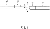
Fig. 1 , in the case where optical fibers with GRIN lenses having GRIN lenses J2 welded to the end faces of optical fibers J1 are connected to each other, when the end face of the GRIN lens J2 is inclined, light from the end face is emitted at an angle θ relative to a machine axis P, and hence a connection in which parallelism of the inclined end face and an offset amount of a pair of the optical fibers with GRIN lenses are adjusted is required. Accordingly, even if the optical fiber with GRIN lens is mounted to the center of the ferrule and the connector connection is to be performed, when the end face of the GRIN lens J2 is inclined, it is not possible to coaxially dispose the ferrules in the cylindrical sleeve. - In the connection in the case where the end face of the optical fiber or the end face of the optical fiber with lens is inclined relative to the machine axis, the optical fiber or the optical fiber with lens is held and fixed using a groove in order to set the parallelism of the end face and the offset amount of the optical fibers or the optical fibers with lenses which are connected to each other with high accuracy (see
PTL 1 and PTL 4). In such a conventional technique, it is not possible to obtain the detachable connector connection with this conventional art. In addition, even when a sleeve which can detachably hold the optical fibers with lenses is to be formed such that the optical fibers with lenses are connected to each other in the state shown inFig. 1 , there has been a problem that it is difficult to inexpensively manufacture the sleeve with high accuracy in the case where zirconia (ceramic) suitable as the sleeve material is used. - In the present invention, coping with such a problem is an example of the task. That is, an object of the present invention is, for example, to provide an inexpensive and highly accurate detachable connector by suppressing the back reflection by inclining the end faces relative to the machine axis when the optical fibers with lenses are connected to each other in a state in which the end faces are not in contact with each other.
- In order to achieve the above object, the connector for optical fibers with lenses according to the present invention includes the following configuration.
- A connector for optical fibers with lenses including a ferrule to which an optical fiber with lens is mounted and which has an end face inclined relative to a central axis, and a coupling member which coaxially couples a pair of the ferrules by making the ferrules to face each other in a non-contact state such that the end faces are parallel to each other, wherein the ferrule includes one or a plurality of holes which are parallel to the central axis at a position decentered from the central axis, the optical fiber with lens being disposed in the hole, and the optical fibers with lenses mounted to the pair of the ferrules have lens end faces inclined along the end faces of the ferrules so as to be optically coupled to each other.
- According to the connector for optical fibers with lenses of the present invention having such features, by having the above-described features, it is possible to provide the inexpensive and highly accurate detachable connector by suppressing the back reflection by inclining the lens end faces relative to the machine axis when the optical fibers with lenses are connected to each other in the state in which the end faces are not in contact with each other and by using the coupling member which coaxially connects the pair of the ferrules together.
-
- [
Fig. 1] Fig. 1 is an explanatory view showing a connection state of optical fibers with lenses having inclined end faces. - [
Fig. 2] Fig. 2 is an explanatory view (Fig. 2(a) is a transverse sectional view andFig. 2(b) is a longitudinal sectional view) showing a connector for optical fibers with lenses which is an embodiment of the present invention. - [
Fig. 3] Fig. 3 is an explanatory view (Fig. 3(a) is a transverse sectional view andFig. 3(b) is a longitudinal sectional view) showing a specific example of the connector for optical fibers with lenses which is the embodiment of the present invention. - [
Fig. 4] Fig. 4 is an explanatory view showing the overall configuration of a connector for optical fibers with lenses (multicore connector) which is an embodiment of the present invention. - [
Fig. 5] Fig. 5 is an explanatory view (Fig. 5(a) is a cross-sectional view andFig. 5(b) is a front view of a ferrule) showing the connection state of the connector for optical fibers with lenses (multicore connector) which is the embodiment of the present invention. - [
Fig. 6] Fig. 6 is an explanatory view (Fig. 6(a) is a cross-sectional view andFig. 6(b) is a front view of the ferrule) showing the connection state of the connector for optical fibers with lenses (multicore connector) which is the embodiment of the present invention. - [
Fig. 7] Fig. 7 is an explanatory view (Fig. 7(a) is a cross-sectional view andFig. 7(b) is a front view of the ferrule) showing the connection state of the connector for optical fibers with lenses (multicore connector) which is the embodiment of the present invention. - Hereinafter, embodiments of the present invention will be described with reference to the drawings. In the following description, the same reference numerals in different drawings denote the same parts, and duplicate description will be appropriately omitted. As shown in
Fig. 2 , a connector for optical fibers withlenses 1 according to the embodiment of the present invention makes optical fibers withlenses 10 in which end parts ofoptical fibers 11 are connected to the centers of lenses (GRIN lenses) 12 by welding to face each other, and performs optical coupling of the optical fibers withlenses 10, and includes a pair offerrules 2 to which the optical fibers withlenses 10 are mounted, and asleeve 3 serving as a coupling member which coaxially couples the pair offerrules 2 by making theferrules 2 to face each other in a non-contact state. - The pair of
ferrules 2 provided with the optical fibers withlenses 10 are identical to each other, and are disposed so as to face each other. As theoptical fiber 11, it is possible to use a single mode optical fiber, a large mode area (LMA) optical fiber, a polarization preserving (polarization maintaining) optical fiber, a multimode optical fiber, a multicore optical fiber, and the like. The outer diameter of thelens 12 may be different from the outer diameter of a clad of theoptical fiber 11, but is preferably equal to that of the clad thereof. The outer diameter of thelens 12 is 125 µm (124.5 to 125.5 µm) in the single mode optical fiber which is used in the field of, e.g., general optical communications. - Each
ferrule 2 has ahole 20 which is formed along a central axis L of a cylindrical body inside the cylindrical body, and the end part of the optical fiber withlens 10 is inserted into thehole 20 and is fixed. In addition, theferrules 2 haveend faces 21 which face each other, and theend faces 21 are inclined relative to the central axis L. In theferrules 2 described above, the end faces 21 of theferrules 2 are inclined and lens end faces of the optical fibers withlenses 10 are inclined along the end faces 21 such that a pair of the optical fibers withlenses 10 are optically coupled to each other. In an example in the drawing, the end faces 21 of theferrules 2 and the lens end faces of the optical fibers withlenses 10 are inclined such that an optical axis P2 of the optical fibers withlenses 10 which are optically coupled to each other between the pair of theferrules 2 intersects an extension of the central axis L. - In each
ferrule 2, thehole 20 which is parallel to the central axis L is formed at a position decentered by a distance S from the central axis L of the outer circumference, and the optical fiber withlens 10 is mounted to thehole 20, whereby a machine axis P1 of the optical fiber withlens 10 is decentered by the distance S from the central axis L. - The
sleeve 3 which coaxially holds the pair of theferrules 2 positions and holds theferrules 2 around the central axis L such that the end faces 21 of the pair of theferrules 2 face each other so as to be symmetrical about a point O at which the optical axis P2 of the optical fibers withlenses 10 which are optically coupled to each other between the pair of theferrules 2 intersects the extension of the central axis L of the outer circumference of theferrule 2. - The central axes L of the pair of the
ferrules 2 are coaxially disposed so as to coincide with the central axis of thesleeve 3 by being held by thesleeve 3. A distance between the end faces 21 of theferrules 2 which face each other in thesleeve 3 is appropriately set such that light emitted from the optical fiber withlens 10 mounted to one of theferrules 2 according to an emission angle θ corresponding to the inclination angle of theend face 21 enters the optical fiber withlens 10 mounted to theother ferrule 2 through the point O. With this, high-efficiency optical coupling between a pair of the optical fibers withlenses 10 is allowed by a simple mechanical engagement in which the pair of theferrules 2 are made to abut on each other in thesleeve 3. - The inclination angle of each of the
end face 21 of theferrule 2 and the end face of the optical fiber withlens 10 may be any angle as long as the angle allows inhibition of reflected return light on the end face and suppression of back reflection. Specifically, the inclination of 4° or more, preferably 6° or more, and further preferably 8° or more with respect to a plane X perpendicular to the optical axis allows effective suppression of the back reflection. -
Fig. 3 shows a more specific example of the configuration of the connector for optical fibers withlenses 1. In this example, in the connector for optical fibers withlenses 1, theferrule 2 includesengaging parts 22 which restrain rotation about the central axis L, and thesleeve 3 includes engagedparts 30 which are engaged by theengaging parts 22 of theferrule 2. In the example shown in the drawing, theengaging part 22 is a flange part provided on the outer circumference of theferrule 2, and theengaged part 30 is a convex or concave part provided to extend along the central axis L inside thesleeve 3. - The
engaging part 22 of theferrule 2 engages theengaged part 30 of thesleeve 3, whereby theferrule 2 is positioned and held around the central axis L in thesleeve 3, and is further positioned such that an interval between theend faces 21 corresponds to a set distance in thesleeve 3. Herein, the engaged part 30 (30A) provided on one end side of thesleeve 3 and a fitted part 30 (30B) provided on the other end side of thesleeve 3 are disposed at positions 180° apart around the central axis L. With this, when theferrules 2 which are identical to each other are inserted into thesleeve 3 and are made to abut on each other, by the engagement between theengaging part 22 and theengaged part 30, it is possible to position theferrules 2 such that the end faces 21 of theferrules 2 face each other so as to be symmetrical about the point O. - The engaging part (flange part) 22 of the
ferrule 2 is disposed at a specific position around the central axis L in a decentering direction toward the machine axis P1 of the optical fiber withlens 10 from the central axis L. That is, the relationship between the position of theengaging part 22 around the central axis L and the decentering direction of the machine axis P1 is uniquely determined. With this, in polishing when the inclined face is formed on theend face 21, it is possible to easily perform working for making the direction of the inclined face to coincide with the decentering direction. When theferrule 2 is set in an apparatus for performing the polishing, theend face 21 of theferrule 2 is fixed with the position of theengaging part 22 directed in a specific direction, and the polishing direction is set for thefixed end face 21. With regard to working of theend face 21, as shown inFig. 3 , theend face 21 may be formed into a curved face. In addition, an anti-reflection coating which uses a dielectric multilayer film or the like may be applied to theend face 21 for the purpose of, for example, reducing Fresnel reflection to improve transmittance or further suppressing the back reflection. Further, theend face 21 can also be coated with a functional film having other functions. - Taking these advantages of the connector for optical fibers with
lenses 1, first, since an emitted light beam is expanded by the lens (GRIN lens) 12 welded to the end part of theoptical fiber 11, in a high power use in large-capacity transmission, it is possible to avert a problem such as damage to theend face 21 caused by a burn by heat generation or a fiber fuse even in the case where a foreign object adheres to theend face 21 by dissipating an energy density on theend face 21. - In addition, by preventing the end faces 21 from coming into contact with each other, it is possible to save labor such as cleaning of a foreign object or dirt on the
end face 21 and, further, it is possible to solve a problem that a dent or a chip occurs on theend face 21 at the time of the insertion and extraction of the connector connection. - Furthermore, by inclining the
end face 21, it becomes possible to suppress the back reflection, and it is possible to implement the connector connection which does not require axis adjustment using theferrule 2 and thesleeve 3. - Further, it is also possible to apply optical design which obtains optical coupling via "beam waist" disclosed in
PTL 2 to the optical fiber withlens 10. In this case, it is possible to design the optical fiber withlens 10 such that the position of the beam waist is positioned on the plane X. -
Fig. 4 shows a connector for optical fibers with lenses 1A according to another embodiment of the present invention. The connector for optical fibers with lenses 1A is a multicore connector, and includes a pair offerrules 2A and guidepins 4 serving as a coupling member which coaxially couples the pair offerrules 2A by making theferrules 2A to face each other in the non-contact state. - As shown in
Fig. 5 to Fig. 7 , in the connector for optical fibers with lenses 1A, eachferrule 2A includes a plurality of theholes 20 and a pair of guide holes 23. In an example shown in each drawing, theferrules 2A have rectangular cross sections, and are disposed so as to face each other with the central axis L directed in a Z direction shown in the drawing. An X direction shown in the drawing is a width direction of theferrule 2A orthogonal to the direction of the central axis L, and a Y direction shown in the drawing is a thickness direction of theferrule 2A orthogonal to the direction of the central axis L. Theguide hole 23 is formed along the central axis L such that theguide pin 4 is inserted along the central axis L. - In the example shown in each of
Fig. 5 to Fig. 7 , similarly to the above-described embodiment, theferrule 2A has theend face 21 which is inclined relative to the central axis. The guide pins 4 are inserted into the guide holes 23 of the pair of theferrules 2A which face each other to thereby couple the pair of theferrules 2A such that the end faces 21 are parallel to each other in the non-contact state. Herein, the guide holes 23 are made coaxial by making theferrules 2A which are identical to each other to face each other in a state in which theferrules 2A are inverted in the Y direction shown in the drawing, and the guide holes 23 in oneferrule 2A are disposed at positions which are symmetrical vertically and horizontally on therectangular end face 21. - The optical fibers with
lenses 10 disposed in a plurality of theholes 20 in oneferrule 2A include the lenses (GRIN lenses) 12 all having the same lens length, and the end faces of thelenses 12 are inclined in the same direction along theend face 21 of theferrule 2A. With this, all of the lights emitted from a plurality of the optical fibers withlenses 10 mounted to oneferrule 2A have the optical axes P2 which are parallel to each other. - In the example shown in
Fig. 5 , in theferrule 2A, a plurality (four in the drawing) of theholes 20 are arranged at regular intervals in parallel to a straight line X1 which connects the centers of the pair of the guide holes 23. An arrangement center G of the plurality of theholes 20 is disposed at a position decentered from the central axis L by a distance S1 in the Y direction shown in the drawing. Herein, theend face 21 and the end face of the optical fiber withlens 10 are inclined relative to the central axis L such that the optical axis P2 of the optical fibers withlenses 10 which are optically coupled to each other is parallel to a straight line which connects the arrangement centers G in the pair of theferrules 2A. - In the example shown in
Fig. 6 , in theferrule 2A, a plurality (four in the drawing) of theholes 20 are disposed in two rows at regular intervals in parallel to the straight line X1 which connects the centers of the pair of the guide holes 23. In addition, the arrangement center G of the plurality of theholes 20 is disposed at a position decentered from the central axis L by a distance S2 in the Y direction shown in the drawing. In this example as well, similarly to the example shown inFig. 5 , theend face 21 and the end face of the optical fiber withlens 10 are inclined relative to the central axis L such that the optical axis P2 of the optical fibers withlenses 10 which are optically coupled to each other is parallel to the straight line which connects the arrangement centers G in the pair of theferrules 2A. - In the example shown in
Fig. 7 , in theferrule 2A, a plurality (four in the drawing) of theholes 20 are disposed at regular intervals on the straight line X1 which connects the centers of the pair of the guide holes 23. In addition, the arrangement center G of the plurality of theholes 20 is disposed at a position decentered from the central axis L by a distance S3 in the X direction shown in the drawing. In this example as well, similarly to the examples shown inFig. 5 andFig. 6 , theend face 21 and the end face of the optical fiber withlens 10 are inclined relative to the central axis L such that the optical axis P2 of the optical fibers withlenses 10 which are optically coupled to each other is parallel to the straight line which connects the arrangement centers G in the pair of theferrules 2A. - According to the embodiment shown in each of
Fig. 4 to Fig. 7 , in the multicore connector for optical fibers with lenses 1A, it is possible to reduce coupling loss due to dust or the like adhering to theend face 21, by the beam expansion by thelens 12 and by spacing the end faces 21 of theferrules 2A apart from each other, and it is possible to eliminate the back reflection caused by the end face reflection, by inclining theend face 21. In addition, by increasing the number of cores, it is possible to cope with an increase in the capacity of optical transmission. - The embodiments of the present invention have been described in detail with reference to the drawings thus far. However, a specific configuration is not limited to the embodiments. Changes of design or the like in a range not departing from the spirit of the present invention are included in the present invention. In addition, unless there are contradiction and problems in the objects, the configurations, and the like in particular in the embodiments described above, the techniques of the embodiments can be applied to each other and combined.
-
- 1, 1A
- Connector for optical fibers with lenses
- 2, 2A
- Ferrule
- 3
- Sleeve
- 4
- Guide pin
- 10
- Optical fiber with lens
- 11
- Optical fiber
- 12
- Lens (GRIN lens)
- 20
- Hole
- 21
- End face
- 22
- Engaging part
- 23
- Guide hole
- 30
- Engaged part
- L
- Central axis
- P1
- Machine axis
- P2
- Optical axis
- G
- Arrangement center
Claims (9)
- A connector for optical fibers with lenses, comprising: a ferrule to which an optical fiber with lens is mounted and which has an end face inclined relative to a central axis; and a coupling member which coaxially couples a pair of said ferrules by making said ferrules to face each other in a non-contact state such that said end faces are parallel to each other, wherein
said ferrule includes one or a plurality of holes which are parallel to said central axis at a position decentered from said central axis, said optical fiber with lens being disposed in the hole, and
said optical fibers with lenses mounted to the pair of said ferrules have lens end faces inclined along the end faces of said ferrules so as to be optically coupled to each other. - The connector for optical fibers with lenses according to claim 1, wherein
said coupling member is a pair of guide pins, said ferrule includes guide holes into which said guide pins are inserted along said central axis,
said plurality of holes are disposed in parallel to a straight line connecting centers of said guide holes, and
an arrangement center of said plurality of holes is disposed at a position decentered from said central axis. - The connector for optical fibers with lenses according to claim 2, wherein the lens end faces of said optical fibers with lenses are inclined such that an optical axis of said optical fibers with lenses which are optically coupled to each other is parallel to a straight line connecting said arrangement centers in the pair of said ferrules.
- The connector for optical fibers with lenses according to claim 1, wherein
said coupling member is a sleeve which coaxially holds the pair of said ferrules,
said optical fiber with lens is disposed in said one hole in said ferrule,
the lens end faces of said optical fibers with lenses are inclined such that an optical axis of said optical fibers with lenses which are coupled to each other intersects an extension of said central axis, and
said sleeve makes said ferrules to face each other on the basis of a point at which said optical axis intersects the extension of said central axis, and positions and holds said ferrules around said central axis. - The connector for optical fibers with lenses according to claim 4, wherein said sleeve positions and holds said ferrules such that the end faces of the pair of said ferrules face each other so as to be symmetrical about a point.
- The connector for optical fibers with lenses according to claim 4 or 5, wherein
said ferrule includes an engaging part which restrains rotation about said central axis,
said sleeve includes an engaged part which is engaged by said engaging part, and
said engaged part provided on one end side of said sleeve and said engaged part provided on another end side of said sleeve are disposed at positions 180° apart around said central axis. - The connector for optical fibers with lenses according to claim 6, wherein the engaging part of said ferrule is disposed at a specified position around said central axis with respect to a decentering direction toward a machine axis of said optical fiber with lens from said central axis.
- The optical fiber with lens according to any one of claims 1 to 7, wherein, in said optical fiber with lens, an end part of an optical fiber is connected to a center of a gradient index lens by welding.
- The connector for optical fibers with lenses according to any one of claims 1 to 8, wherein back reflection of said optical fiber with lens is -50 dB or less.
Applications Claiming Priority (2)
| Application Number | Priority Date | Filing Date | Title |
|---|---|---|---|
| JP2015144667 | 2015-07-22 | ||
| PCT/JP2016/064372 WO2017013930A1 (en) | 2015-07-22 | 2016-05-13 | Connector for optical fibers with lenses |
Publications (2)
| Publication Number | Publication Date |
|---|---|
| EP3327475A1 true EP3327475A1 (en) | 2018-05-30 |
| EP3327475A4 EP3327475A4 (en) | 2019-02-27 |
Family
ID=57834940
Family Applications (1)
| Application Number | Title | Priority Date | Filing Date |
|---|---|---|---|
| EP16827494.2A Ceased EP3327475A4 (en) | 2015-07-22 | 2016-05-13 | OPTICAL FIBER CONNECTOR COMPRISING LENSES |
Country Status (6)
| Country | Link |
|---|---|
| US (1) | US10564365B2 (en) |
| EP (1) | EP3327475A4 (en) |
| JP (1) | JP6806059B2 (en) |
| KR (1) | KR20180022769A (en) |
| CN (1) | CN107850740A (en) |
| WO (1) | WO2017013930A1 (en) |
Cited By (1)
| Publication number | Priority date | Publication date | Assignee | Title |
|---|---|---|---|---|
| WO2024133462A1 (en) * | 2022-12-22 | 2024-06-27 | Orange | Interconnecting a hollow-core fibre with a standard silica single-mode fibre |
Families Citing this family (10)
| Publication number | Priority date | Publication date | Assignee | Title |
|---|---|---|---|---|
| US11573377B2 (en) * | 2015-10-12 | 2023-02-07 | 3M Innovative Properties Company | Optical waveguide positioning feature in a multiple waveguides connector |
| JP6601248B2 (en) * | 2016-02-10 | 2019-11-06 | 住友電気工業株式会社 | Optical connector ferrule and optical connector |
| EP3602159A4 (en) * | 2017-03-29 | 2020-12-30 | Commscope Technologies LLC | Multi-fiber fiber optic connector |
| DE102017220516A1 (en) * | 2017-11-16 | 2019-05-16 | Laser Components Gmbh | Fiber assembly, resonator and method of making a fiber assembly |
| JP7115050B2 (en) * | 2018-06-12 | 2022-08-09 | 住友電気工業株式会社 | fiber optic amplifier |
| CN114341689A (en) * | 2019-08-28 | 2022-04-12 | 京瓷株式会社 | Optical module and optical module |
| WO2021091949A1 (en) | 2019-11-05 | 2021-05-14 | US Conec, Ltd | Lensed fiber optic ferrule with simplified molding |
| US12222557B2 (en) | 2020-01-24 | 2025-02-11 | Us Conec Ltd. | Ferrule with molded internal tilted refractive surfaces |
| JP7601369B2 (en) * | 2020-11-13 | 2024-12-17 | 湖北工業株式会社 | Optical Filter Device |
| CN112731594B (en) * | 2021-03-31 | 2021-08-17 | 武汉光谷航天三江激光产业技术研究院有限公司 | Intelligent optical fiber coupling system and method |
Family Cites Families (22)
| Publication number | Priority date | Publication date | Assignee | Title |
|---|---|---|---|---|
| JPS5934507A (en) * | 1982-08-21 | 1984-02-24 | Nippon Sheet Glass Co Ltd | Optical fiber terminal which prevents interference of returned light |
| JPS5938707A (en) * | 1982-08-30 | 1984-03-02 | Fujitsu Ltd | Optical fiber connector |
| JP2996602B2 (en) * | 1995-01-31 | 2000-01-11 | 株式会社精工技研 | Optical branching coupler for constant polarization optical fiber |
| US20020176644A1 (en) * | 2001-03-16 | 2002-11-28 | Bhagavatula Venkata A. | Polarization combiner/splitter |
| US6520689B2 (en) * | 2001-07-17 | 2003-02-18 | Corning Incorporated | Optical fiber splicing method and device |
| US7031567B2 (en) * | 2001-07-24 | 2006-04-18 | Tyco Electronics Corporation | Expanded beam connector system |
| JP2003121679A (en) | 2001-10-11 | 2003-04-23 | Seiko Instruments Inc | Optical fiber device using optical fiber having end face formed obliquely |
| US7218811B2 (en) * | 2002-01-10 | 2007-05-15 | The Furukawa Electric Co., Ltd. | Optical module, and multi-core optical collimator and lens housing therefor |
| JP2005037731A (en) * | 2003-07-16 | 2005-02-10 | Nippon Telegr & Teleph Corp <Ntt> | Optical connector |
| JP4037346B2 (en) | 2003-10-08 | 2008-01-23 | 東洋ガラス株式会社 | Optical fiber coupling parts |
| WO2007046141A1 (en) | 2005-10-19 | 2007-04-26 | Toyo Glass Co., Ltd. | Production table of optical fiber collimator unit, production method of optical fiber collimator unit, and optical fiber collimator unit |
| JP2008020560A (en) | 2006-07-11 | 2008-01-31 | Toyo Glass Co Ltd | Pair of optical fiber collimators and optical fiber collimator array |
| JP4219380B2 (en) * | 2006-10-11 | 2009-02-04 | 日本航空電子工業株式会社 | Optical fiber, marker groove forming apparatus, method thereof, and method of producing optical fiber device |
| JP4925323B2 (en) | 2007-08-21 | 2012-04-25 | 東洋ガラス株式会社 | Optical fiber collimator and optical fiber collimator array manufacturing method |
| US9102563B2 (en) * | 2009-10-15 | 2015-08-11 | Greg S. Laughlin | Environmentally rugged free-space fiber waveguide connector and method of manufacture thereof |
| JP5216151B1 (en) | 2012-03-15 | 2013-06-19 | 株式会社フジクラ | Optical fiber combiner and laser device using the same |
| CN103676022B (en) | 2012-08-30 | 2016-12-21 | 鸿富锦精密工业(深圳)有限公司 | Fiber coupling lens and the joints of optical fibre |
| US9022669B2 (en) * | 2012-12-21 | 2015-05-05 | Corning Cable Systems Llc | Gradient index lens assemblies, fiber optic connectors, and fiber optic cable assemblies employing lens alignment channels |
| US10162127B2 (en) * | 2013-10-15 | 2018-12-25 | Commscope, Inc. Of North Carolina | Expanded beam array for fiber optics |
| JP6459334B2 (en) * | 2014-09-18 | 2019-01-30 | 住友電気工業株式会社 | Ferrule and optical connection structure |
| JP6502142B2 (en) * | 2015-03-26 | 2019-04-17 | 株式会社フジクラ | Optical fiber ferrule, optical connector system, and method of manufacturing optical fiber ferrule |
| US10197743B2 (en) * | 2015-05-22 | 2019-02-05 | US Conec, Ltd | Multi-fiber ferrule with improved eye safety |
-
2016
- 2016-05-13 WO PCT/JP2016/064372 patent/WO2017013930A1/en not_active Ceased
- 2016-05-13 EP EP16827494.2A patent/EP3327475A4/en not_active Ceased
- 2016-05-13 CN CN201680042797.9A patent/CN107850740A/en active Pending
- 2016-05-13 JP JP2017529482A patent/JP6806059B2/en active Active
- 2016-05-13 US US15/580,464 patent/US10564365B2/en active Active
- 2016-05-13 KR KR1020187000062A patent/KR20180022769A/en not_active Ceased
Cited By (1)
| Publication number | Priority date | Publication date | Assignee | Title |
|---|---|---|---|---|
| WO2024133462A1 (en) * | 2022-12-22 | 2024-06-27 | Orange | Interconnecting a hollow-core fibre with a standard silica single-mode fibre |
Also Published As
| Publication number | Publication date |
|---|---|
| US10564365B2 (en) | 2020-02-18 |
| EP3327475A4 (en) | 2019-02-27 |
| US20180143383A1 (en) | 2018-05-24 |
| JP6806059B2 (en) | 2021-01-06 |
| CN107850740A (en) | 2018-03-27 |
| WO2017013930A1 (en) | 2017-01-26 |
| KR20180022769A (en) | 2018-03-06 |
| JPWO2017013930A1 (en) | 2018-05-10 |
Similar Documents
| Publication | Publication Date | Title |
|---|---|---|
| US10564365B2 (en) | Connector for optical fibers with lenses | |
| EP2267509B1 (en) | Optical fiber connection structure and endoscope system | |
| US10007062B2 (en) | Optical fiber assembly | |
| US10605996B2 (en) | Expanded beam optical connector and method of making the same | |
| TWI665482B (en) | Socket | |
| JP2007193006A (en) | Optical component for optical communication | |
| CN102281811A (en) | Laterally emitting device and method of manufacturing same | |
| US20120243251A1 (en) | Lateral light emitting device and method of producing the same | |
| US10036857B2 (en) | Expanded beam connector with discrete alignment assembly | |
| US20170160491A1 (en) | Eye-safe interface for optical connector | |
| EP3470897A1 (en) | Multicore optical connector and method for manufacturing same | |
| US8675284B2 (en) | Truncated ball lens for an expanded beam connector | |
| WO2017015279A1 (en) | Eye-safe interface for optical connector | |
| JP7139518B2 (en) | Lensed fiber optic connector with feedback mirror assembly | |
| Childers et al. | High density, low cost, no-polish optical ferrule | |
| WO2020133644A1 (en) | Optical path switching structure for handle of oral laser treatment device | |
| CN116931200B (en) | 400G DR4 optical device | |
| JP2014202891A (en) | Optical connector | |
| JP2004029450A (en) | Optical connector | |
| US20100046888A1 (en) | Optical connector | |
| WO2018042795A1 (en) | Method for manufacturing optical connector | |
| CN105572817A (en) | Abnormal end surface optical fiber coupler used for integration | |
| JPH01234804A (en) | Method of connecting optical fibers | |
| TW201830074A (en) | Optical coupler and laser apparatus comprising the same | |
| JP2008046185A (en) | Manufacturing method of optical fiber with lens |
Legal Events
| Date | Code | Title | Description |
|---|---|---|---|
| STAA | Information on the status of an ep patent application or granted ep patent |
Free format text: STATUS: THE INTERNATIONAL PUBLICATION HAS BEEN MADE |
|
| PUAI | Public reference made under article 153(3) epc to a published international application that has entered the european phase |
Free format text: ORIGINAL CODE: 0009012 |
|
| STAA | Information on the status of an ep patent application or granted ep patent |
Free format text: STATUS: REQUEST FOR EXAMINATION WAS MADE |
|
| 17P | Request for examination filed |
Effective date: 20180122 |
|
| AK | Designated contracting states |
Kind code of ref document: A1 Designated state(s): AL AT BE BG CH CY CZ DE DK EE ES FI FR GB GR HR HU IE IS IT LI LT LU LV MC MK MT NL NO PL PT RO RS SE SI SK SM TR |
|
| AX | Request for extension of the european patent |
Extension state: BA ME |
|
| DAV | Request for validation of the european patent (deleted) | ||
| DAX | Request for extension of the european patent (deleted) | ||
| A4 | Supplementary search report drawn up and despatched |
Effective date: 20190125 |
|
| RIC1 | Information provided on ipc code assigned before grant |
Ipc: G02B 6/32 20060101AFI20190121BHEP Ipc: G02B 6/26 20060101ALI20190121BHEP Ipc: G02B 6/38 20060101ALI20190121BHEP |
|
| STAA | Information on the status of an ep patent application or granted ep patent |
Free format text: STATUS: EXAMINATION IS IN PROGRESS |
|
| 17Q | First examination report despatched |
Effective date: 20200424 |
|
| REG | Reference to a national code |
Ref country code: DE Ref legal event code: R003 |
|
| STAA | Information on the status of an ep patent application or granted ep patent |
Free format text: STATUS: THE APPLICATION HAS BEEN REFUSED |
|
| 18R | Application refused |
Effective date: 20251219 |