EP3327352B1 - Detektion/zündkerze für wasserkessel und verfahren zur herstellung einer solchen zündkerze - Google Patents
Detektion/zündkerze für wasserkessel und verfahren zur herstellung einer solchen zündkerze Download PDFInfo
- Publication number
- EP3327352B1 EP3327352B1 EP17203655.0A EP17203655A EP3327352B1 EP 3327352 B1 EP3327352 B1 EP 3327352B1 EP 17203655 A EP17203655 A EP 17203655A EP 3327352 B1 EP3327352 B1 EP 3327352B1
- Authority
- EP
- European Patent Office
- Prior art keywords
- sleeve
- hole
- spark plug
- main electrode
- plate
- Prior art date
- Legal status (The legal status is an assumption and is not a legal conclusion. Google has not performed a legal analysis and makes no representation as to the accuracy of the status listed.)
- Active
Links
Images


Classifications
-
- F—MECHANICAL ENGINEERING; LIGHTING; HEATING; WEAPONS; BLASTING
- F23—COMBUSTION APPARATUS; COMBUSTION PROCESSES
- F23Q—IGNITION; EXTINGUISHING-DEVICES
- F23Q3/00—Igniters using electrically-produced sparks
- F23Q3/006—Details
-
- H—ELECTRICITY
- H01—ELECTRIC ELEMENTS
- H01T—SPARK GAPS; OVERVOLTAGE ARRESTERS USING SPARK GAPS; SPARKING PLUGS; CORONA DEVICES; GENERATING IONS TO BE INTRODUCED INTO NON-ENCLOSED GASES
- H01T13/00—Sparking plugs
- H01T13/20—Sparking plugs characterised by features of the electrodes or insulation
- H01T13/34—Sparking plugs characterised by features of the electrodes or insulation characterised by the mounting of electrodes in insulation, e.g. by embedding
-
- H—ELECTRICITY
- H01—ELECTRIC ELEMENTS
- H01T—SPARK GAPS; OVERVOLTAGE ARRESTERS USING SPARK GAPS; SPARKING PLUGS; CORONA DEVICES; GENERATING IONS TO BE INTRODUCED INTO NON-ENCLOSED GASES
- H01T21/00—Apparatus or processes specially adapted for the manufacture or maintenance of spark gaps or sparking plugs
- H01T21/02—Apparatus or processes specially adapted for the manufacture or maintenance of spark gaps or sparking plugs of sparking plugs
Definitions
- the invention relates to a detection/ignition spark plug for boilers.
- the invention further relates to a method for producing such spark plug.
- Spark plugs are known and available in the market, which are configured to be at least partially housed inside combustion chambers of boilers. These known spark lugs usually comprise:
- the aforesaid components are assembled with one another in subsequent steps and with different coupling technologies.
- the coupling between the connecting terminal and the electrode is carried out with a different technology and in a following moment relative to the coupling between the sleeve and the electrode.
- the connecting terminal is coupled to the electrode through welding.
- one of the known technologies used for the aforesaid coupling involves the use of metallic rings interposed between the surface of the ceramic body of the spark plug and the inner surface of the housing hole.
- the rings are deformed so that they can adhere, on one side, to the surface of the ceramic body of the spark plug and, on the other side, to the inner surface of the housing hole.
- This fixing mode is affected by some evident problems, which are mainly due to the fact that the exerted mechanical forces can lead to a movement of the spark plug from its operating position or can locally generate pressure peaks, which cause the ceramic sleeve to break.
- a different known technique used to couple the ceramic sleeve to the plate involves the use of a glass material as a fixing material between the ceramic sleeve and the plate.
- the glass material is applied in the solid phase, for example in the form of a glass ring, which is brought to the liquid phase through heating, before going back to the solid state.
- micro-cracks can be created during the manual bending step to which the conductor wire is subjected following the firing step. These micro-cracks do not evidently ensure the seal to smokes. Furthermore, taking into account the fact that the electrode is subjected to continuous thermal changes, which change the morphology of the micro-cracks, you can experience actual detachments of the parts.
- EP2388523 refers to a method for fixing igniters for boilers or the like. According to EP2388523 the method includes insertion of said igniter into a hole for receiving the ceramic body of the igniter, which receiving hole is formed in a wall or fixing plate. Means for fixing and sealing the igniter to said fixing plate being provided in said gap area wherein said fixing and sealing means consist of a glassy material.
- JP2013127846 relates to a reformer spark plug used when igniting a fuel supplied to a reformer of a fuel cell. The spark plug of JP2013127846 discloses the presence of a sealing glass for connecting the spark plug components.
- the object of the invention is to provide an alternative spark plug for boilers or the like.
- the object of the invention is to provide a spark plug and a relative production method, which allow manufacturers to overcome the drawbacks of the prior art discussed above in a simple and economic fashion, both from a functional point of view and from a constructive point of view.
- the invention relates to a spark plug comprising:
- the fixing material is such that it can be applied in the fluid phase, so as to adhere to the connecting terminal, to the main electrode, to the sleeve and to the fixing plate, and subsequently solidified, for example through heating of the spark plug in an oven.
- all the components contributing to the creation of the spark plug are fixed to one another by means of the same technology, namely the application of the fixing material. Therefore, after the consolidation of the fixing material, the spark plug is ready to be used without any further thermal or mechanical treatment.
- the sleeve is preferably made of a ceramic material.
- the sleeve can be entirely made of glass, or you can have a ceramic sleeve coated, both on the inside and on the outside, with glass cylinders. Alternatively, you can have a glass cylinder that can be housed inside the sleeve containing the main electrode.
- all the fixing material application seats are arranged on the outside of the combustion chamber, namely they are all accessible from a side, the upper one, of the plate.
- the invention preferably establishes that:
- part of the enlarged portion of the main housing hole of the main electrode is occupied by the glass cylinder mentioned above.
- the glass cylinder ends before the connecting terminal, so as to leave a volume, which is delimited by the cylinder itself, by the electrode, by the sleeve and by the connecting terminal, for receiving the fixing material.
- the non-enlarged parts of the aforesaid holes are cylindrical portions and substantially have the same dimensions as the component, sleeve or electrode to be housed by them.
- the fixing material does not necessarily penetrate the cylindrical sections of the holes.
- the coupling hole of the sleeve can be obtained through a counterbore, namely with walls that are parallel to the axis of the electrode and are not flared, as set forth in the example indicated above.
- the coupling hole of the sleeve can be made as a through hole having a greater diameter than the sleeve.
- greater diameter we mean a diameter that is such as as to allow the fixing material to be inserted.
- a gasket is needed, which is configured to prevent the fixing material from getting out towards the lower surface of the fixing plate. Said gasket can be directly inserted into the hole, remaining flush with the lower surface of the fixing plate, or it can be coupled on the outside of the hole along the lower surface of the fixing plate.
- a mask can be provided, which is configured to hold the components of the spark plug in position and to permit an easy application of the fixing material.
- the hole on the inside of the connecting terminal has a greater length than the upper end of the main electrode projecting out of the sleeve.
- the fixing material is also applied in the upper free portion of said hole of the electrode.
- the fixing material acts as a plug, thus further fixing the connecting terminal to the electrode.
- the upper end of the main electrode projecting out of the sleeve is flush with the outer edge of the connecting terminal.
- the remaining elements usually making up a spark plug for boilers or the like namely the ground electrode and a fixing bracket, can be fixed to the spark plug described above in a known manner, for example by welding the ground electrode and the bracket to one another in a following step, or they can be fixed in the novel manner that will be described hereinafter.
- the spark plug comprises a ground electrode and the plate comprises a secondary hole to house the ground electrode.
- Said hole is provided with an enlarged portion for receiving the fixing material in the area of the upper surface of the plate.
- This hole as well, can have a flared shape or can be obtained through a counterbore, like the main hole for receiving the sleeve of the electrode.
- the ground electrode is fixed to the plate at the same time and in the same way in which the remaining components are fixed to one another.
- the enlarged portion of the hole for receiving the ground electrode is accessible from the upper surface of the plate.
- the spark plug comprises a metallic ring, which is housed inside the enlarged portion of the secondary hole of the plate and is configured to create a conductive bridge between the ground electrode and the plate, when the fixing material is applied in the enlarged portion of the secondary hole.
- the fixing material used in this invention comprises a ceramic material, in particular compositions of silica-soda or silica-alumina.
- manufacturers can avoid the formation of the aforesaid micro-cracks, which develop using the glass material according to the prior art.
- the plate can comprise a through housing, for example of the same type as the sleeve containing hole, which houses an inspection glass, namely a glass lens, which, as it is transparent, allows you to look inside the combustion chamber to check whether there is a flame or not.
- a through housing for example of the same type as the sleeve containing hole, which houses an inspection glass, namely a glass lens, which, as it is transparent, allows you to look inside the combustion chamber to check whether there is a flame or not.
- the innovation besides the use of the ceramic material as fixing material, lies in the fact that said element is placed in position in the same moment as the other components, so that the spark plug taken out of the oven is ready to be used without further machining steps.
- the method for the production of the spark plug described above comprises the step of placing all the components of the spark plug in an assembling mask, which is configured to hold said components in an operating position even in the absence of the fixing material. Subsequently, the method comprise the step of applying the fixing material in the fluid form in the relative seats described above and of heating the spark plug supported by the mask, so as to cause the fixing material to reach the solid phase.
- the method also comprises the preliminary step of bending, by means of suitable bending machines, both the main conductor and the ground conductor, which are then placed in the mask already in the correct and ready-for-use form.
- This preliminary bending step avoids causing stresses to the fixing material.
- ground conductor or the main conductor can be preliminarily subjected to chemical treatments or they can be covered with other metals, in order to improve their performances.
- this treatment step is prior to the the mask assembling step, which produces, after the heating, a spark plug that is already ready to be used.
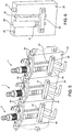
- FIG. 1 is a schematic perspective view of an example of a spark plug according to the invention.
- the spark plug 1 comprises a main electrode 2 and a secondary or ground electrode 3. These electrodes 2, 3 are supported by a plate 4 so as to have an end inside a combustion chamber of a boiler and another end outside the same combustion chamber.
- the secondary electrode 3 projects out of the combustion chamber only along a short section of the plate 4, whereas the main electrode 2 is coupled to a sleeve 5, preferably a ceramic one, which is housed in a hole 9 of the plate 4.
- the end of the main electrode 2 projecting out of the sleeve 5 on the outer side of the combustion chamber is coupled to a connecting terminal 6.
- FIG. 1 shows the presence of fixing material 8 between the sleeve 5 and the plate 4, between the secondary electrode 3 and the plate 4 and on top of the connecting terminal 6.
- the spark plug 1 of figure 1 further comprises a bracket 7, which is fixed to the plate 4 on the outside of the combustion chamber. Even though you cannot see it in figure 1 , the same fixing material 8 is also present between the bracket 7 and the plate 4.
- figure 1 shows side holes 16 to help produce the spark plug 1. The use of these holes 16 will be best understood upon perusal of the description of figures 5 and 6 . Indeed, said holes 16 are designed both to fix the plate to the combustion chamber and to couple the spark plug to an assembling mask during the production step.
- Figures 2-4 show more in detail the seats for receiving the fixing material 8.
- figure 3 shows how the holes 9 and 12 for receiving the sleeve 5 and the secondary electrode 3 comprise an enlarged and flared portion 11, 14 in the area of the upper surface 32 of the plate 4.
- the remaining portions of the holes 9 and 12 are cylindrical portions 10, 13 having dimensions that are substantially equal to the sleeve 5 and the secondary electrode 3.
- the lower surface 33 of the plate 4 has neither projections nor recesses in the area of the holes 9, 12.
- a metallic ring 15 which, on one side, surrounds the secondary electrode 3 and, on the other side, is in contact with the plate 4, preferably a metallic one.
- Figure 4 shows a cross section of the coupling area of the main electrode 2 to the sleeve 5 and to the connecting terminal 6.
- these couplings are obtained with the same fixing material 8.
- the inner hole 17 of the sleeve 5 comprises an enlarged portion 19 at its upper end, where the fixing material 8 is applied.
- the connecting terminal 6 has an inner hole 20, as well, which is provided with an enlarged portion 22, which, in use, faces the enlarged portion 19 of the hole 17 of the sleeve 5.
- Figure 4 also shows the fact the main electrode 2 ends before the upper edge of the hole 20 of the connecting terminal 6 and that this free portion of the hole 20 is filled with the fixing material 8.
- Figure 5 shows a schematic view of a support mask of three spark plugs for the positioning of the fixing material and figure 6 shows a portion of this mask in the absence of the spark plugs.
- the mask 23 comprises two seats 29, 30 for longitudinally housing the sleeve 5 and the secondary electrode 3.
- the mask 23 comprises holes 28, which, in use, are aligned with the holes 16 of the plate 4, so that pins 24 can fix the spark plug 1 to the mask 23.
- the system further comprises a front plate 25, which is coupled by means of pins (not shown) housed in relative holes 26 and is configured to hold the sleeve 5 and the secondary electrode 3 in the relative seats 29, 30.
- the plate 25 comprises striking projecting portions for the electrodes 2, 3.
- the fixing material 8 is, in particular, a ceramic material, which turns from fluid into solid when it is heated.
- ideal ceramic materials for this invention are compositions of silica-soda or silica-alumina.
- Silica-alumina compositions comprise, in turn, silica and alumina compounds, silicon compounds, dinas compounds, kyanite compounds, sillimanite compounds, mullite compounds, bauxite compounds, corundum compounds.
- Figures 7-9 show alternative embodiments for the coupling of the sleeve 5 of the main electrode 2 in the relative hole 9.
- the hole 9 comprises an enlarged portion 11', which, however, is not tapered like in the example of figure 3 , but is obtained through a counterbore and has walls that are parallel to the axis of the hole 9.
- the hole 12 for receiving the secondary electrode 3 also comprises an enlarged portion, which can be obtained through a counterbore with walls that are parallel to the axis of the relative hole.
- the hole 9 is a through hole 11" having a greater diameter than the sleeve 5. Therefore, these examples involve the use of a gasket 34, which is configured to prevent the fixing material 8 from getting out of the lower surface 33 of the plate 4.
- the gasket 34 is housed in the hole 9 and is flush with the lower surface 33 of the plate 4.
- the gasket 34 is on the outside of the hole 9 and is fixed to the lower surface 33 of the plate 4.
- Figure 10 shows an alternative embodiment of the main electrode 2 relative to figure 4 .
- the enlarged portion 19 of the hole 17 extends from the upper end of the sleeve 5 past the plate 4.
- a glass cylinder 35 which, in turn, houses the main electrode. Since the glass cylinder 35 has a smaller length than the enlarged portion 19 of the hole 17, in the area of the upper end of the sleeve 5 there is a volume that is enclosed, on the lower side, by the glass cylinder 35, on the inside, by the main electrode 2, on the outside, by the sleeve 5 and, on the upper side, by the connecting terminal 6.
- this volume is filled with the fixing material 8 in the fluid form, so that, when it is heated, it causes all the aforesaid elements to become integral to one another.
- the hole 20 of the connecting terminal 6 does not have enlarged portions and ends flush with the edge of the electrode 2.
- the main hole for receiving the sleeve 5 is obtained through a counterbore.
- this hole can also be made in other ways, for example - preferably - in the ways shown in figures 4 , 8 or 9 .
Landscapes
- Engineering & Computer Science (AREA)
- Manufacturing & Machinery (AREA)
- Chemical & Material Sciences (AREA)
- Combustion & Propulsion (AREA)
- Mechanical Engineering (AREA)
- General Engineering & Computer Science (AREA)
- Spark Plugs (AREA)
- Fats And Perfumes (AREA)
- Burglar Alarm Systems (AREA)
Claims (8)
- Detektions-/Zündkerze für Heizkessel, wobei die Zündkerze (1) umfasst:- eine fadenförmige Hauptelektrode (2) und eine Masseelektrode (3);- eine Hülse (5) zur Aufnahme eines Zwischenabschnitts der Hauptelektrode (2);- eine Befestigungsplatte (4), die mit einer unteren Oberfläche, die ausgebildet ist, der Brennkammer des Kessels zugewandt zu sein, einer oberen Oberfläche, die der Brennkammer gegenüberliegt, und einem Aufnahmeloch (9) für die Hülse (5) versehen ist, so dass ein unteres Ende der Hauptelektrode (2) innerhalb der Brennkammer und ein oberes Ende der Hauptelektrode (2) außerhalb der Brennkammer ist;- ein Verbindungsterminal (6), das mit dem oberen Ende der Hauptelektrode (2) in Reihe mit der Hülse (5) gekoppelt ist;- Befestigungsmaterial (8), das in einer Vielzahl von Befestigungsmaterial-Applikationsplätzen zwischen dem Verbindungsterminal (6) und dem oberen Ende der Hauptelektrode (2) zwischen der Hauptelektrode (2) und der Hülse (5) und zwischen der Hülse (5) und der Befestigungsplatte (4) aufgebracht ist;
wobei das Befestigungsmaterial (8) ein Material ist, das zunächst in den von Befestigungsmaterial-Applikationsplätzen in der flüssigen Phase appliziert wird, so dass es an dem Verbindungsterminal (6) zur Hauptelektrode (2) an der Hülse (5) und an der Befestigungsplatte (4) haftet, und anschließend in die feste Phase gebracht wird;
dadurch gekennzeichnet, dass die Platte (4) ein sekundäres Loch (12) zur Aufnahme der Masseelektrode (3) umfasst, wobei das besagte Loch mit einem vergrößerten Abschnitt (14) in Bezug auf die Masseelektrode (3) an der oberen Oberfläche (32) der Platte (4) zur Aufnahme des Befestigungsmaterials (8) versehen ist; wobei alle Befestigungsmaterial-Applikationsplätze an der Außenseite der Brennkammer angeordnet und von der oberen Oberfläche der Befestigungsplatte (4) aus zugänglich sind. - Zündkerze wie in Anspruch 1 beansprucht, wobei- das Aufnahmeloch (9) einen gegenüber der Hülse (5) vergrößerten Abschnitt (11, 11', 11") an der oberen Oberfläche (32) der Platte (4) zur Aufnahme des Befestigungsmaterials (8) aufweist;- die Hülse (5) ein Hauptloch (17) zur Aufnahme der Hauptelektrode (2) aufweist, wobei das Loch (17) einen vergrößerten Abschnitt (19) an dem oberen Ende der Hauptelektrode (2) zur Aufnahme des Befestigungsmaterials (8) aufweist;- das Verbindungsterminal (6) ein Loch (20) zur Aufnahme des oberen Endes der Hauptelektrode (2) aufweist, wobei das Loch (20) einen vergrößerten Abschnitt (22) an der Hülse (5) zur Aufnahme des Befestigungsmaterials (8) aufweist.
- Zündkerze wie in Anspruch 2 beansprucht, wobei das Loch des Verbindungsterminals (6) eine größere Länge aufweist als das aus der Hülse (5) herausragende obere Ende der Hauptelektrode (2), wobei das Befestigungsmaterial (8) in dem oberen freien Abschnitt des Lochs (20) appliziert ist.
- Zündkerze wie in Anspruch 1 beansprucht, wobei- das Aufnahmeloch (9) einen gegenüber der Hülse (5) vergrößerten Abschnitt (11, 11', 11") an der oberen Oberfläche (32) der Platte (4) zur Aufnahme des Befestigungsmaterials (8) aufweist;- die Hülse (5) ein Hauptloch (17) zur Aufnahme der Hauptelektrode (2) aufweist, wobei das Loch (17) einen vergrößerten Abschnitt (19) aufweist, der sich von dem oberen Ende der Hauptelektrode (2) über die Platte (4) hinaus erstreckt,- ein Glaszylinder, welcher teilweise in dem vergrößerten Abschnitt (19) des Lochs (17) der Hülse (5), die die Hauptelektrode (2) aufnimmt, untergebracht ist und vor dem oberen Rand der Hülse endet, um ein Aufnahmevolumen für das Befestigungsmaterial (8) zu schaffen;- das Verbindungsterminals (6) ein Loch (20) aufweist, das das obere Ende der Hauptelektrode (2) aufnimmt.
- Zündkerze wie in Anspruch 1 beansprucht, wobei die Zündkerze (1) einen metallischen Ring (15) umfasst, der innerhalb des vergrößerten Abschnitts (14) des sekundären Lochs (12) der Platte (4) aufgenommen ist und ausgebildet ist, eine leitende Brücke zwischen der Masseelektrode (3) und der Platte (4) zu realisieren, wenn das Befestigungsmaterial (8) innerhalb des vergrößerten Abschnitts (14) appliziert ist.
- Zündkerze wie in einem der vorangehenden Ansprüche beansprucht, wobei das Befestigungsmaterial (8) ein keramisches Material umfasst.
- Verfahren zur Realisierung einer Detektions-/Zündkerze für Heizkessel, wobei das Verfahren die folgenden Schritte umfasst:a) Bereitstellen einer Zündkerze (1) umfassend:- eine fadenförmige Hauptelektrode (2) und eine Masseelektrode (3);- eine Hülse (5) zur Aufnahme eines Zwischenabschnitts der Hauptelektrode (2);- eine Befestigungsplatte (4) mit einem Aufnahmeloch (9) für die Hülse (5);b) Bereitstellen einer Maske (23) zum Zusammenbauen der Zündkerze (1), die ausgebildet ist, die Elemente der Zündkerze in Abwesenheit des Befestigungsmaterials in Position zu halten;c) Applizieren eines Befestigungsmaterials (8) in flüssiger Form zwischen der Hauptelektrode (2) und der Hülse (5) und zwischen der Hülse (5) und der Befestigungsplatte (4);d) Erwärmen der Zündkerze (1), die in der Maske (23) gehalten wird, so dass das Befestigungsmaterial (8) zwischen der Hauptelektrode (2) und der Hülse (5) und zwischen der Hülse (5) und der Befestigungsplatte (4) in die feste Phase gebracht wird; wobei gemäß Schritt a) die Zündkerze ein Verbindungsterminal (6) umfasst, das mit der Hauptelektrode (2) gekoppelt werden kann; gemäß Schritt c) das Befestigungsmaterial (8) zwischen dem Verbindungsterminal (6) und der Hauptelektrode (2) appliziert wird;
dadurch gekennzeichnet, dass
gemäß Schritt a) die Platte (4) ein sekundäres Loch (12) zur Aufnahme der Masseelektrode (3) aufweist, wobei das besagte Loch mit einem vergrößerten Abschnitt (14) in Bezug auf die Masseelektrode (5) an der oberen Oberfläche (32) der Platte (4) zur Aufnahme des Befestigungsmaterials (8) versehen ist;
gemäß Schritt c) das Befestigungsmaterial (8) zwischen der Platte (4) und der Masseelektrode (3) appliziert wird. - Verfahren wie in Anspruch 7 beansprucht, wobei gemäß Schritt a) die Zündkerze einen metallischen Ring (15) umfasst, der innerhalb des sekundären Lochs (12) der Platte (4) untergebracht ist; gemäß Schritt c) das Befestigungsmaterial (8) zwischen der Platte (4) und der Masseelektrode (3) nach der Positionierung des metallischen Rings (15) appliziert wird.
Applications Claiming Priority (1)
| Application Number | Priority Date | Filing Date | Title |
|---|---|---|---|
| IT102016000119329A IT201600119329A1 (it) | 2016-11-24 | 2016-11-24 | Candela di accensione/rilevazione per caldaie o simili, sistema e metodo per produrre tale candela |
Publications (2)
| Publication Number | Publication Date |
|---|---|
| EP3327352A1 EP3327352A1 (de) | 2018-05-30 |
| EP3327352B1 true EP3327352B1 (de) | 2021-05-19 |
Family
ID=58347781
Family Applications (1)
| Application Number | Title | Priority Date | Filing Date |
|---|---|---|---|
| EP17203655.0A Active EP3327352B1 (de) | 2016-11-24 | 2017-11-24 | Detektion/zündkerze für wasserkessel und verfahren zur herstellung einer solchen zündkerze |
Country Status (2)
| Country | Link |
|---|---|
| EP (1) | EP3327352B1 (de) |
| IT (1) | IT201600119329A1 (de) |
Citations (1)
| Publication number | Priority date | Publication date | Assignee | Title |
|---|---|---|---|---|
| JP2013127846A (ja) * | 2011-12-16 | 2013-06-27 | Futaba Industrial Co Ltd | 改質器用点火プラグ |
Family Cites Families (2)
| Publication number | Priority date | Publication date | Assignee | Title |
|---|---|---|---|---|
| DE19749105A1 (de) * | 1997-11-06 | 1999-06-10 | Beru Ag | Stromdurchführungselement |
| IT1399888B1 (it) * | 2010-05-18 | 2013-05-09 | Castfutura Spa | Metodo e dispositivo di fissaggio per candele d'accensione di caldaie o simili |
-
2016
- 2016-11-24 IT IT102016000119329A patent/IT201600119329A1/it unknown
-
2017
- 2017-11-24 EP EP17203655.0A patent/EP3327352B1/de active Active
Patent Citations (1)
| Publication number | Priority date | Publication date | Assignee | Title |
|---|---|---|---|---|
| JP2013127846A (ja) * | 2011-12-16 | 2013-06-27 | Futaba Industrial Co Ltd | 改質器用点火プラグ |
Also Published As
| Publication number | Publication date |
|---|---|
| IT201600119329A1 (it) | 2018-05-24 |
| EP3327352A1 (de) | 2018-05-30 |
Similar Documents
| Publication | Publication Date | Title |
|---|---|---|
| CN103038960B (zh) | 预燃室火花塞 | |
| CN100510737C (zh) | 传感器及其制造方法 | |
| JP6057960B2 (ja) | スパークプラグ、および、スパークプラグの製造方法 | |
| JP4944928B2 (ja) | プラズマジェット点火プラグおよびその製造方法 | |
| EP2139084B1 (de) | Verfahren zur Herstellung einer Zündkerze und Zündkerze, die durch das Verfahren hergestellt wird | |
| JP2009224345A5 (de) | ||
| KR20110081957A (ko) | 스파크 플러그 | |
| KR20140022435A (ko) | 스파크 플러그 전극 구성 | |
| JP2009224344A5 (de) | ||
| CN110925099B (zh) | 一种发火咀组件可更换的点火电嘴及其安装方法 | |
| EP3327352A1 (de) | Detektion/zündkerze für kessel oder ähnliches system und verfahren zur herstellung solch einer zündkerze | |
| JP2012501523A (ja) | 複合セラミック電極、複合セラミック電極を有する点火装置、およびそれらの製造方法 | |
| JP6045464B2 (ja) | スパークプラグの製造方法、および、スパークプラグ | |
| JP6405039B2 (ja) | グローピンプラグ | |
| ITTO20110738A1 (it) | Dispositivo per la connessione di una termocoppia ad un gruppo elettromagnete di sicurezza e rubinetto gas in un piano di cottura | |
| EP3161382B1 (de) | System und verfahren zur befestigung eines detektionsstabs und/oder von zündfunkenkerzen und eines inspektionsfensters von boilern oder dergleichen | |
| JP2016522386A (ja) | 内側接触型セラミック製加熱要素を備えたシーズ型グロープラグおよびその製造方法 | |
| ITGE20100053A1 (it) | Metodo e dispositivo di fissaggio per candele d'accensione di caldaie o simili | |
| CN105934632B (zh) | 用于气体燃烧器组件的点火器及具有点火器的烹饪器具 | |
| CN101711420A (zh) | 带有点燃辅助部件的高压放电灯 | |
| CN103017612A (zh) | 低成本点火器 | |
| JP2835209B2 (ja) | セラミックヒータ | |
| KR20160044789A (ko) | 압력센서 글로우 플러그 | |
| JP6283768B2 (ja) | グロープラグ | |
| JP7600839B2 (ja) | スパークプラグ |
Legal Events
| Date | Code | Title | Description |
|---|---|---|---|
| PUAI | Public reference made under article 153(3) epc to a published international application that has entered the european phase |
Free format text: ORIGINAL CODE: 0009012 |
|
| STAA | Information on the status of an ep patent application or granted ep patent |
Free format text: STATUS: THE APPLICATION HAS BEEN PUBLISHED |
|
| AK | Designated contracting states |
Kind code of ref document: A1 Designated state(s): AL AT BE BG CH CY CZ DE DK EE ES FI FR GB GR HR HU IE IS IT LI LT LU LV MC MK MT NL NO PL PT RO RS SE SI SK SM TR |
|
| AX | Request for extension of the european patent |
Extension state: BA ME |
|
| STAA | Information on the status of an ep patent application or granted ep patent |
Free format text: STATUS: REQUEST FOR EXAMINATION WAS MADE |
|
| 17P | Request for examination filed |
Effective date: 20181128 |
|
| RBV | Designated contracting states (corrected) |
Designated state(s): AL AT BE BG CH CY CZ DE DK EE ES FI FR GB GR HR HU IE IS IT LI LT LU LV MC MK MT NL NO PL PT RO RS SE SI SK SM TR |
|
| STAA | Information on the status of an ep patent application or granted ep patent |
Free format text: STATUS: EXAMINATION IS IN PROGRESS |
|
| 17Q | First examination report despatched |
Effective date: 20200120 |
|
| GRAP | Despatch of communication of intention to grant a patent |
Free format text: ORIGINAL CODE: EPIDOSNIGR1 |
|
| STAA | Information on the status of an ep patent application or granted ep patent |
Free format text: STATUS: GRANT OF PATENT IS INTENDED |
|
| INTG | Intention to grant announced |
Effective date: 20201201 |
|
| GRAS | Grant fee paid |
Free format text: ORIGINAL CODE: EPIDOSNIGR3 |
|
| GRAA | (expected) grant |
Free format text: ORIGINAL CODE: 0009210 |
|
| STAA | Information on the status of an ep patent application or granted ep patent |
Free format text: STATUS: THE PATENT HAS BEEN GRANTED |
|
| RAP3 | Party data changed (applicant data changed or rights of an application transferred) |
Owner name: POWER TECHNOLOGY S.R.L. |
|
| AK | Designated contracting states |
Kind code of ref document: B1 Designated state(s): AL AT BE BG CH CY CZ DE DK EE ES FI FR GB GR HR HU IE IS IT LI LT LU LV MC MK MT NL NO PL PT RO RS SE SI SK SM TR |
|
| REG | Reference to a national code |
Ref country code: GB Ref legal event code: FG4D |
|
| REG | Reference to a national code |
Ref country code: CH Ref legal event code: EP |
|
| REG | Reference to a national code |
Ref country code: DE Ref legal event code: R096 Ref document number: 602017038761 Country of ref document: DE |
|
| REG | Reference to a national code |
Ref country code: AT Ref legal event code: REF Ref document number: 1394328 Country of ref document: AT Kind code of ref document: T Effective date: 20210615 |
|
| REG | Reference to a national code |
Ref country code: IE Ref legal event code: FG4D |
|
| REG | Reference to a national code |
Ref country code: LT Ref legal event code: MG9D |
|
| REG | Reference to a national code |
Ref country code: AT Ref legal event code: MK05 Ref document number: 1394328 Country of ref document: AT Kind code of ref document: T Effective date: 20210519 |
|
| REG | Reference to a national code |
Ref country code: NL Ref legal event code: MP Effective date: 20210519 |
|
| PG25 | Lapsed in a contracting state [announced via postgrant information from national office to epo] |
Ref country code: HR Free format text: LAPSE BECAUSE OF FAILURE TO SUBMIT A TRANSLATION OF THE DESCRIPTION OR TO PAY THE FEE WITHIN THE PRESCRIBED TIME-LIMIT Effective date: 20210519 Ref country code: BG Free format text: LAPSE BECAUSE OF FAILURE TO SUBMIT A TRANSLATION OF THE DESCRIPTION OR TO PAY THE FEE WITHIN THE PRESCRIBED TIME-LIMIT Effective date: 20210819 Ref country code: AT Free format text: LAPSE BECAUSE OF FAILURE TO SUBMIT A TRANSLATION OF THE DESCRIPTION OR TO PAY THE FEE WITHIN THE PRESCRIBED TIME-LIMIT Effective date: 20210519 Ref country code: FI Free format text: LAPSE BECAUSE OF FAILURE TO SUBMIT A TRANSLATION OF THE DESCRIPTION OR TO PAY THE FEE WITHIN THE PRESCRIBED TIME-LIMIT Effective date: 20210519 Ref country code: LT Free format text: LAPSE BECAUSE OF FAILURE TO SUBMIT A TRANSLATION OF THE DESCRIPTION OR TO PAY THE FEE WITHIN THE PRESCRIBED TIME-LIMIT Effective date: 20210519 |
|
| PG25 | Lapsed in a contracting state [announced via postgrant information from national office to epo] |
Ref country code: GR Free format text: LAPSE BECAUSE OF FAILURE TO SUBMIT A TRANSLATION OF THE DESCRIPTION OR TO PAY THE FEE WITHIN THE PRESCRIBED TIME-LIMIT Effective date: 20210820 Ref country code: IS Free format text: LAPSE BECAUSE OF FAILURE TO SUBMIT A TRANSLATION OF THE DESCRIPTION OR TO PAY THE FEE WITHIN THE PRESCRIBED TIME-LIMIT Effective date: 20210919 Ref country code: LV Free format text: LAPSE BECAUSE OF FAILURE TO SUBMIT A TRANSLATION OF THE DESCRIPTION OR TO PAY THE FEE WITHIN THE PRESCRIBED TIME-LIMIT Effective date: 20210519 Ref country code: RS Free format text: LAPSE BECAUSE OF FAILURE TO SUBMIT A TRANSLATION OF THE DESCRIPTION OR TO PAY THE FEE WITHIN THE PRESCRIBED TIME-LIMIT Effective date: 20210519 Ref country code: SE Free format text: LAPSE BECAUSE OF FAILURE TO SUBMIT A TRANSLATION OF THE DESCRIPTION OR TO PAY THE FEE WITHIN THE PRESCRIBED TIME-LIMIT Effective date: 20210519 Ref country code: PT Free format text: LAPSE BECAUSE OF FAILURE TO SUBMIT A TRANSLATION OF THE DESCRIPTION OR TO PAY THE FEE WITHIN THE PRESCRIBED TIME-LIMIT Effective date: 20210920 Ref country code: NO Free format text: LAPSE BECAUSE OF FAILURE TO SUBMIT A TRANSLATION OF THE DESCRIPTION OR TO PAY THE FEE WITHIN THE PRESCRIBED TIME-LIMIT Effective date: 20210819 Ref country code: PL Free format text: LAPSE BECAUSE OF FAILURE TO SUBMIT A TRANSLATION OF THE DESCRIPTION OR TO PAY THE FEE WITHIN THE PRESCRIBED TIME-LIMIT Effective date: 20210519 |
|
| PG25 | Lapsed in a contracting state [announced via postgrant information from national office to epo] |
Ref country code: NL Free format text: LAPSE BECAUSE OF FAILURE TO SUBMIT A TRANSLATION OF THE DESCRIPTION OR TO PAY THE FEE WITHIN THE PRESCRIBED TIME-LIMIT Effective date: 20210519 |
|
| PG25 | Lapsed in a contracting state [announced via postgrant information from national office to epo] |
Ref country code: SK Free format text: LAPSE BECAUSE OF FAILURE TO SUBMIT A TRANSLATION OF THE DESCRIPTION OR TO PAY THE FEE WITHIN THE PRESCRIBED TIME-LIMIT Effective date: 20210519 Ref country code: SM Free format text: LAPSE BECAUSE OF FAILURE TO SUBMIT A TRANSLATION OF THE DESCRIPTION OR TO PAY THE FEE WITHIN THE PRESCRIBED TIME-LIMIT Effective date: 20210519 Ref country code: CZ Free format text: LAPSE BECAUSE OF FAILURE TO SUBMIT A TRANSLATION OF THE DESCRIPTION OR TO PAY THE FEE WITHIN THE PRESCRIBED TIME-LIMIT Effective date: 20210519 Ref country code: DK Free format text: LAPSE BECAUSE OF FAILURE TO SUBMIT A TRANSLATION OF THE DESCRIPTION OR TO PAY THE FEE WITHIN THE PRESCRIBED TIME-LIMIT Effective date: 20210519 Ref country code: EE Free format text: LAPSE BECAUSE OF FAILURE TO SUBMIT A TRANSLATION OF THE DESCRIPTION OR TO PAY THE FEE WITHIN THE PRESCRIBED TIME-LIMIT Effective date: 20210519 Ref country code: RO Free format text: LAPSE BECAUSE OF FAILURE TO SUBMIT A TRANSLATION OF THE DESCRIPTION OR TO PAY THE FEE WITHIN THE PRESCRIBED TIME-LIMIT Effective date: 20210519 Ref country code: ES Free format text: LAPSE BECAUSE OF FAILURE TO SUBMIT A TRANSLATION OF THE DESCRIPTION OR TO PAY THE FEE WITHIN THE PRESCRIBED TIME-LIMIT Effective date: 20210519 |
|
| REG | Reference to a national code |
Ref country code: DE Ref legal event code: R097 Ref document number: 602017038761 Country of ref document: DE |
|
| PLBE | No opposition filed within time limit |
Free format text: ORIGINAL CODE: 0009261 |
|
| STAA | Information on the status of an ep patent application or granted ep patent |
Free format text: STATUS: NO OPPOSITION FILED WITHIN TIME LIMIT |
|
| 26N | No opposition filed |
Effective date: 20220222 |
|
| PG25 | Lapsed in a contracting state [announced via postgrant information from national office to epo] |
Ref country code: IS Free format text: LAPSE BECAUSE OF FAILURE TO SUBMIT A TRANSLATION OF THE DESCRIPTION OR TO PAY THE FEE WITHIN THE PRESCRIBED TIME-LIMIT Effective date: 20210919 Ref country code: AL Free format text: LAPSE BECAUSE OF FAILURE TO SUBMIT A TRANSLATION OF THE DESCRIPTION OR TO PAY THE FEE WITHIN THE PRESCRIBED TIME-LIMIT Effective date: 20210519 |
|
| PG25 | Lapsed in a contracting state [announced via postgrant information from national office to epo] |
Ref country code: MC Free format text: LAPSE BECAUSE OF FAILURE TO SUBMIT A TRANSLATION OF THE DESCRIPTION OR TO PAY THE FEE WITHIN THE PRESCRIBED TIME-LIMIT Effective date: 20210519 |
|
| REG | Reference to a national code |
Ref country code: CH Ref legal event code: PL |
|
| PG25 | Lapsed in a contracting state [announced via postgrant information from national office to epo] |
Ref country code: LU Free format text: LAPSE BECAUSE OF NON-PAYMENT OF DUE FEES Effective date: 20211124 Ref country code: IT Free format text: LAPSE BECAUSE OF FAILURE TO SUBMIT A TRANSLATION OF THE DESCRIPTION OR TO PAY THE FEE WITHIN THE PRESCRIBED TIME-LIMIT Effective date: 20210519 Ref country code: BE Free format text: LAPSE BECAUSE OF NON-PAYMENT OF DUE FEES Effective date: 20211130 |
|
| REG | Reference to a national code |
Ref country code: BE Ref legal event code: MM Effective date: 20211130 |
|
| PG25 | Lapsed in a contracting state [announced via postgrant information from national office to epo] |
Ref country code: IE Free format text: LAPSE BECAUSE OF NON-PAYMENT OF DUE FEES Effective date: 20211124 |
|
| PG25 | Lapsed in a contracting state [announced via postgrant information from national office to epo] |
Ref country code: FR Free format text: LAPSE BECAUSE OF NON-PAYMENT OF DUE FEES Effective date: 20211130 |
|
| PG25 | Lapsed in a contracting state [announced via postgrant information from national office to epo] |
Ref country code: HU Free format text: LAPSE BECAUSE OF FAILURE TO SUBMIT A TRANSLATION OF THE DESCRIPTION OR TO PAY THE FEE WITHIN THE PRESCRIBED TIME-LIMIT; INVALID AB INITIO Effective date: 20171124 |
|
| PG25 | Lapsed in a contracting state [announced via postgrant information from national office to epo] |
Ref country code: CY Free format text: LAPSE BECAUSE OF FAILURE TO SUBMIT A TRANSLATION OF THE DESCRIPTION OR TO PAY THE FEE WITHIN THE PRESCRIBED TIME-LIMIT Effective date: 20210519 |
|
| PG25 | Lapsed in a contracting state [announced via postgrant information from national office to epo] |
Ref country code: LI Free format text: LAPSE BECAUSE OF NON-PAYMENT OF DUE FEES Effective date: 20220701 Ref country code: CH Free format text: LAPSE BECAUSE OF NON-PAYMENT OF DUE FEES Effective date: 20220701 |
|
| PGFP | Annual fee paid to national office [announced via postgrant information from national office to epo] |
Ref country code: GB Payment date: 20231121 Year of fee payment: 7 |
|
| PGFP | Annual fee paid to national office [announced via postgrant information from national office to epo] |
Ref country code: DE Payment date: 20231127 Year of fee payment: 7 |
|
| PG25 | Lapsed in a contracting state [announced via postgrant information from national office to epo] |
Ref country code: MK Free format text: LAPSE BECAUSE OF FAILURE TO SUBMIT A TRANSLATION OF THE DESCRIPTION OR TO PAY THE FEE WITHIN THE PRESCRIBED TIME-LIMIT Effective date: 20210519 |
|
| PG25 | Lapsed in a contracting state [announced via postgrant information from national office to epo] |
Ref country code: MT Free format text: LAPSE BECAUSE OF FAILURE TO SUBMIT A TRANSLATION OF THE DESCRIPTION OR TO PAY THE FEE WITHIN THE PRESCRIBED TIME-LIMIT Effective date: 20210519 |
|
| REG | Reference to a national code |
Ref country code: DE Ref legal event code: R119 Ref document number: 602017038761 Country of ref document: DE |
|
| GBPC | Gb: european patent ceased through non-payment of renewal fee |
Effective date: 20241124 |
|
| PG25 | Lapsed in a contracting state [announced via postgrant information from national office to epo] |
Ref country code: DE Free format text: LAPSE BECAUSE OF NON-PAYMENT OF DUE FEES Effective date: 20250603 |
|
| PG25 | Lapsed in a contracting state [announced via postgrant information from national office to epo] |
Ref country code: GB Free format text: LAPSE BECAUSE OF NON-PAYMENT OF DUE FEES Effective date: 20241124 |
|
| PG25 | Lapsed in a contracting state [announced via postgrant information from national office to epo] |
Ref country code: TR Free format text: LAPSE BECAUSE OF FAILURE TO SUBMIT A TRANSLATION OF THE DESCRIPTION OR TO PAY THE FEE WITHIN THE PRESCRIBED TIME-LIMIT Effective date: 20210519 |