EP3327289A1 - Rotary compressor and refrigeration cycle device - Google Patents
Rotary compressor and refrigeration cycle device Download PDFInfo
- Publication number
- EP3327289A1 EP3327289A1 EP16830110.9A EP16830110A EP3327289A1 EP 3327289 A1 EP3327289 A1 EP 3327289A1 EP 16830110 A EP16830110 A EP 16830110A EP 3327289 A1 EP3327289 A1 EP 3327289A1
- Authority
- EP
- European Patent Office
- Prior art keywords
- blade
- oil supply
- supply groove
- cylinder
- rotary compressor
- Prior art date
- Legal status (The legal status is an assumption and is not a legal conclusion. Google has not performed a legal analysis and makes no representation as to the accuracy of the status listed.)
- Granted
Links
Images



Classifications
-
- F—MECHANICAL ENGINEERING; LIGHTING; HEATING; WEAPONS; BLASTING
- F01—MACHINES OR ENGINES IN GENERAL; ENGINE PLANTS IN GENERAL; STEAM ENGINES
- F01C—ROTARY-PISTON OR OSCILLATING-PISTON MACHINES OR ENGINES
- F01C21/00—Component parts, details or accessories not provided for in groups F01C1/00 - F01C20/00
- F01C21/08—Rotary pistons
- F01C21/0809—Construction of vanes or vane holders
-
- F—MECHANICAL ENGINEERING; LIGHTING; HEATING; WEAPONS; BLASTING
- F04—POSITIVE - DISPLACEMENT MACHINES FOR LIQUIDS; PUMPS FOR LIQUIDS OR ELASTIC FLUIDS
- F04C—ROTARY-PISTON, OR OSCILLATING-PISTON, POSITIVE-DISPLACEMENT MACHINES FOR LIQUIDS; ROTARY-PISTON, OR OSCILLATING-PISTON, POSITIVE-DISPLACEMENT PUMPS
- F04C18/00—Rotary-piston pumps specially adapted for elastic fluids
- F04C18/30—Rotary-piston pumps specially adapted for elastic fluids having the characteristics covered by two or more of groups F04C18/02, F04C18/08, F04C18/22, F04C18/24, F04C18/48, or having the characteristics covered by one of these groups together with some other type of movement between co-operating members
- F04C18/34—Rotary-piston pumps specially adapted for elastic fluids having the characteristics covered by two or more of groups F04C18/02, F04C18/08, F04C18/22, F04C18/24, F04C18/48, or having the characteristics covered by one of these groups together with some other type of movement between co-operating members having the movement defined in group F04C18/08 or F04C18/22 and relative reciprocation between the co-operating members
- F04C18/356—Rotary-piston pumps specially adapted for elastic fluids having the characteristics covered by two or more of groups F04C18/02, F04C18/08, F04C18/22, F04C18/24, F04C18/48, or having the characteristics covered by one of these groups together with some other type of movement between co-operating members having the movement defined in group F04C18/08 or F04C18/22 and relative reciprocation between the co-operating members with vanes reciprocating with respect to the outer member
- F04C18/3562—Rotary-piston pumps specially adapted for elastic fluids having the characteristics covered by two or more of groups F04C18/02, F04C18/08, F04C18/22, F04C18/24, F04C18/48, or having the characteristics covered by one of these groups together with some other type of movement between co-operating members having the movement defined in group F04C18/08 or F04C18/22 and relative reciprocation between the co-operating members with vanes reciprocating with respect to the outer member the inner and outer member being in contact along one line or continuous surfaces substantially parallel to the axis of rotation
- F04C18/3564—Rotary-piston pumps specially adapted for elastic fluids having the characteristics covered by two or more of groups F04C18/02, F04C18/08, F04C18/22, F04C18/24, F04C18/48, or having the characteristics covered by one of these groups together with some other type of movement between co-operating members having the movement defined in group F04C18/08 or F04C18/22 and relative reciprocation between the co-operating members with vanes reciprocating with respect to the outer member the inner and outer member being in contact along one line or continuous surfaces substantially parallel to the axis of rotation the surfaces of the inner and outer member, forming the working space, being surfaces of revolution
-
- F—MECHANICAL ENGINEERING; LIGHTING; HEATING; WEAPONS; BLASTING
- F04—POSITIVE - DISPLACEMENT MACHINES FOR LIQUIDS; PUMPS FOR LIQUIDS OR ELASTIC FLUIDS
- F04C—ROTARY-PISTON, OR OSCILLATING-PISTON, POSITIVE-DISPLACEMENT MACHINES FOR LIQUIDS; ROTARY-PISTON, OR OSCILLATING-PISTON, POSITIVE-DISPLACEMENT PUMPS
- F04C29/00—Component parts, details or accessories of pumps or pumping installations, not provided for in groups F04C18/00 - F04C28/00
- F04C29/02—Lubrication; Lubricant separation
-
- F—MECHANICAL ENGINEERING; LIGHTING; HEATING; WEAPONS; BLASTING
- F04—POSITIVE - DISPLACEMENT MACHINES FOR LIQUIDS; PUMPS FOR LIQUIDS OR ELASTIC FLUIDS
- F04C—ROTARY-PISTON, OR OSCILLATING-PISTON, POSITIVE-DISPLACEMENT MACHINES FOR LIQUIDS; ROTARY-PISTON, OR OSCILLATING-PISTON, POSITIVE-DISPLACEMENT PUMPS
- F04C2280/00—Arrangements for preventing or removing deposits or corrosion
Definitions
- Embodiments of the present invention relate to a rotary compressor and a refrigeration cycle device.
- a configuration including a container in which lubricating oil is stored and a compression mechanism accommodated in the container is known.
- the compression mechanism includes a cylindrical cylinder, a closing plate which closes an opening of the cylinder, and a roller which rotates eccentrically in a cylinder chamber formed with the cylinder and the closing plate.
- a blade groove formed in the cylinder a blade dividing the inside of the cylinder chamber into a compression chamber and a suction chamber is disposed. The blade is in contact with the roller and advances into and retreats from the inside of the cylinder chamber in accordance with eccentric rotation of the roller.
- the above-described blade slide with respect to the closing plate in a state in which lubricating oil is interposed between the blade and the closing plate. Thereby, it is considered that sealing between the blade and the closing plate can be secured while reducing abrasion between the blade and the closing plate.
- a configuration for interposing lubricating oil between the blade and the closing plate a configuration in which an oil supply groove extending in a movement direction of the blade is formed on a surface of the blade facing the closing plate is conceivable. Specifically, a first end of the oil supply groove opens toward an inside of the container outside the cylinder chamber. A second end of the oil supply groove terminates within the blade. According to this configuration, since lubricating oil in the container is introduced into the oil supply groove, it is considered that lubricating oil is easily supplied between the blade and the closing plate.
- the present invention is directed to providing a rotary compressor and a refrigeration cycle device in which operation reliability can be maintained over a long period of time.
- a rotary compressor of an embodiment includes a container, a cylinder, a closing plate, a roller, a blade, and an oil supply groove.
- the container stores lubricating oil.
- the cylinder is accommodated in the container.
- the closing plate closes an opening of the cylinder and forms a cylinder chamber together with the cylinder.
- the roller eccentrically rotates in the cylinder chamber.
- the blade is provided in a blade groove formed in the cylinder, in contact with the roller to divide an inside of the cylinder chamber, and able to advance into and retreat from the inside of the cylinder chamber in accordance with eccentric rotation of the roller.
- the oil supply groove is formed on a facing surface of the blade facing the closing plate and extends in a movement direction of the blade.
- the oil supply groove has a first end which communicates with an inside of the container outside the cylinder chamber and a second end terminated within the blade.
- Surface roughness of a bottom surface of the oil supply groove is smaller than surface roughness of a back surface positioned close to the first end in outer surfaces of the blade.
- FIG. 1 is a schematic configuration view of the refrigeration cycle device 1 including a cross-sectional view of a rotary compressor 2 in a first embodiment.
- the refrigeration cycle device 1 of the present embodiment includes the rotary compressor 2, a radiator (condenser) 3 connected to the rotary compressor 2, an expansion device 4 connected to the radiator 3, and an evaporator 5 connected between the expansion device 4 and the rotary compressor 2.
- the rotary compressor 2 is a so-called rotary type compressor.
- the rotary compressor 2 compresses a low-pressure gaseous refrigerant introduced into the rotary compressor 2 into a high-temperature and high-pressure gaseous refrigerant.
- a specific configuration of the rotary compressor 2 will be described below.
- the radiator 3 radiates heat from the high-temperature and high-pressure gaseous refrigerant sent from the rotary compressor 2, and converts the high-temperature and high-pressure gaseous refrigerant into a high-pressure liquid refrigerant.
- the expansion device 4 reduces the pressure of the high-pressure liquid refrigerant sent from the radiator 3 and converts the high-pressure liquid refrigerant into a low-temperature and low-pressure liquid refrigerant.
- the evaporator 5 evaporates the low-temperature and low-pressure liquid refrigerant sent from the expansion device 4 and converts the low-temperature and low-pressure liquid refrigerant into a low-pressure gaseous refrigerant.
- evaporation of the low-pressure liquid refrigerant dissipates evaporation heat from the surroundings, and thus the surroundings are cooled.
- the low-pressure gaseous refrigerant that has passed through the evaporator 5 is introduced into the rotary compressor 2 described above.
- a refrigerant serving as a working fluid circulates while changing its phase between a gaseous refrigerant and a liquid refrigerant.
- the rotary compressor 2 of the present embodiment includes a compressor main body 11 and an accumulator 12.
- the accumulator 12 is a so-called gas-liquid separator.
- the accumulator 12 is provided between the evaporator 5 and the compressor main body 11 described above.
- the accumulator 12 is connected to the compressor main body 11 via a suction pipe 21.
- the accumulator 12 supplies only the gaseous refrigerant among the gaseous refrigerant evaporated in the evaporator 5 and the liquid refrigerant not evaporated in the evaporator 5 to the compressor main body 11.
- the compressor main body 11 includes a rotating shaft 31, an electric motor 32, a compression mechanism 33, and a sealed container (container) 34 which accommodates the rotating shaft 31, the electric motor 32, and the compression mechanism 33.
- the sealed container 34 is formed in a cylindrical shape. Opposite end of the sealed container 34 in a direction of the axis O are closed. Lubricating oil J is contained in the sealed container 34. A portion of the compression mechanism 33 is immersed in the lubricating oil J.
- the rotating shaft 31 is disposed coaxially along the axis O of the sealed container 34.
- a direction along the axis O is simply referred to as an axial direction
- a portion close to the electric motor 32 in the axial direction is referred to as an upper side
- a portion close to the compression mechanism 33 in the axial direction is referred to as a lower side.
- a direction perpendicular to the axial direction is referred to as a radial direction
- a direction around the axis O is referred to as a circumferential direction.
- the electric motor 32 is a so-called inner rotor type direct current (DC) brushless motor.
- the electric motor 32 includes a cylindrical stator 35 and a columnar rotor 36 disposed on an inner side of the stator 35.
- the stator 35 is fixed to an inner wall surface of the sealed container 34 by shrinkage-fitting or the like.
- the rotor 36 is fixed to an upper portion of the rotating shaft 31.
- the rotor 36 is disposed on the inner side of the stator 35 at an interval in the radial direction.
- the compression mechanism 33 includes a cylindrical cylinder 41, a main bearing (closing plate) 42 and a sub bearing (closing plate) 43 for closing opposite end openings of the cylinder 41.
- the rotating shaft 31 passes through the cylinder 41.
- the main bearing 42 and the sub bearing 43 rotatably support the rotating shaft 31.
- a space formed by the cylinder 41, the main bearing 42, and the sub bearing 43 constitutes a cylinder chamber 46 (see FIG. 2 ).
- An eccentric portion 51 that is eccentric in the radial direction with respect to the axis O is formed at a portion positioned inside the cylinder chamber 46 in the above-described rotating shaft 31.
- a roller 53 is externally fitted to the eccentric portion 51.
- the roller 53 is configured to be eccentrically rotatable with respect to the axis O while an outer circumferential surface thereof is in sliding contact with an inner circumferential surface of the cylinder 41 according to rotation of the rotating shaft 31.
- FIG. 2 is a cross-sectional view of the compression mechanism 33 corresponding to a line II-II of FIG. 1 .
- a blade groove 54 recessed toward the outside in the radial direction is formed at a portion in the circumferential direction of the cylinder 41.
- the blade groove 54 is formed over the entire axial direction of the cylinder 41.
- the blade groove 54 communicates with the inside of the sealed container 34 at an outer end in the radial direction.
- a blade 55 is provided in the blade groove 54.
- the blade 55 is configured to be slidably movable in the radial direction with respect to the cylinder 41.
- an outer end surface (hereinafter referred to as a back surface) of the blade 55 in the radial direction is urged toward the inside in the radial direction by an urging member 57.
- an inner end surface (hereinafter referred to as a distal end surface) of the blade 55 in the radial direction is in contact with an outer circumferential surface of the roller 53 in the cylinder chamber 46.
- the blade 55 is configured to be able to advance into and retreat from the cylinder chamber 46 according to eccentric rotation of the roller 53.
- the distal end surface of the blade 55 is formed in an arc shape which is protrudes toward the inside in the radial direction. A specific configuration of the blade 55 will be described below.
- the cylinder chamber 46 is divided into a suction chamber and a compression chamber by the roller 53 and the blade 55.
- a compression operation is performed in the cylinder chamber 46 by a rotating operation of the roller 53 and an advancing and retreating operation of the blade 55.
- a suction hole 56 that penetrates the cylinder 41 in the radial direction is formed at a portion positioned on an back side of the blade groove 54 (left side of the blade groove 54 in FIG. 2 ) in a rotation direction (see the arrow in FIG. 2 ) of the roller 53.
- the suction pipe 21 (see FIG. 1 ) described above is connected to the suction hole 56 from the outer end in the radial direction.
- an inner end in the radial direction of the suction hole 56 opens into the cylinder chamber 46.
- a discharge groove 58 is formed at a portion positioned on a front side of the blade groove 54 (right side of the blade groove 54 in FIG. 2 ) in the rotation direction of the roller 53.
- the discharge groove 58 is formed in a semicircular shape in a plan view seen from the axial direction.
- the main bearing 42 closes an upper end opening of the cylinder 41.
- the main bearing 42 rotatably supports a portion of the rotating shaft 31 positioned above the cylinder 41.
- the main bearing 42 includes a tube 61 through which the rotating shaft 31 is inserted, and a flange 62 protruding toward the outside in the radial direction from a lower end of the tube 61.
- a discharge hole 64 penetrating the flange 62 in the axial direction is formed at a portion of the flange 62 in the circumferential direction.
- the discharge hole 64 communicates with the inside of the cylinder chamber 46 through the above-described discharge groove 58.
- a discharge valve mechanism (not shown) which opens and closes the discharge hole 64 in accordance with a pressure increase in the cylinder chamber 46 (compression chamber) and discharges a refrigerant to the outside of the cylinder chamber 46 is disposed in the flange 62.
- a muffler 65 which covers the main bearing 42 from above is provided on the main bearing 42.
- a communication hole 66 is formed in the muffler 65 to communicate the inside and outside of the muffler 65.
- the high-temperature and high-pressure gaseous refrigerant discharged through the above-described discharge hole 64 is discharged into the sealed container 34 through the communication hole 66.
- the sub bearing 43 closes a lower end opening of the cylinder 41.
- the sub bearing 43 rotatably supports a portion of the rotating shaft 31 positioned below the cylinder 41.
- the sub bearing 43 includes a tube 71 through which the rotating shaft 31 is inserted, and a flange 72 protruding toward the outside in the radial direction from an upper end of the tube 71.
- the blade 55 described above is formed in a rectangular shape extending in the radial direction.
- the lubricating oil J is interposed between the blade 55 and inner wall surfaces of the blade groove 54, and the flange s 62 and 72 of the respective bearings 42 and 43. Therefore, side surfaces of the blade 55 facing the blade groove 54 (side surfaces toward opposite sides in a width direction (circumferential direction)) can slide on the inner wall surfaces of the blade groove 54 with an oil film interposed therebetween.
- an upper end surface of the blade 55 can slide on a lower surface of the flange 62 with the oil film interposed therebetween.
- a lower end surface of the blade 55 can slide on an upper surface of the flange 72 with the oil film interposed therebetween. That is, in the blade 55 of the present embodiment, portions of the outer surfaces excluding the above-described back surface (the side surface, the upper end surface, and the lower end surface) function as sliding surfaces.
- oil supply grooves 81 recessed toward an inner side in the axial direction extend in the radial direction at a center in a blade width direction.
- the oil supply grooves 81 extend in a straight line in the radial direction (a movement direction of the blade 55) in a plan view seen from the axial direction.
- a groove width H of the oil supply grooves 81 is made uniform throughout the radial direction. Further, the oil supply grooves 81 can be formed by a cutting process using a disk-shaped cutter or the like.
- a volume of the oil supply grooves 81 is preferably set in accordance with a capacity of the lubricating oil J required for the operation region (hereinafter referred to as a latter half of a compression stroke) in which the blade 55 shifts from a bottom dead center at which the blade 55 protrudes most in the cylinder chamber 46 to the top dead center at which the blade 55 is retreated most from the cylinder chamber 46.
- each of the oil supply groove 81 has a straight extending portion 82 positioned close to the outer end (first end) in the radial direction and an inclined portion 83 continuous to the inner end (second end) in the radial direction of the straight extending portion 82.
- a groove depth in the axial direction is made uniform throughout the radial direction.
- the outer end in the radial direction opens on the back surface of the blade 55.
- the outer end in the radial direction of the straight extending portion 82 communicates with the inside of the sealed container 34 outside the cylinder chamber 46 through the blade groove 54.
- the lubricating oil J stored in the sealed container 34 is introduced into the oil supply groove 81 through the blade groove 54.
- the oil supply groove 81 has a maximum groove depth E (depth of the straight extending portion 82 in the present embodiment) which is larger than the groove width H (see FIG. 2 ).
- the groove depth gradually decreases toward the inner side in the radial direction.
- a bottom surface of the inclined portion 83 is formed in an arc shape which is protrudes toward the inner side in the axial direction in a side view seen from the blade width direction.
- the inner end in the radial direction of the inclined portion 83 is terminated within the blade 55 in a state in which it is close to the distal end surface (the second end surface) of the blade 55. That is, the oil supply groove 81 does not reach the distal end surface of the blade 55 and does not communicate with the inside of the cylinder chamber 46. Further, the oil supply groove 81 is formed such that at least the inclined portion 83 is positioned in the cylinder chamber 46 when the blade 55 protrudes most in the cylinder chamber 46.
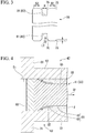
- FIG. 3 is a cross-sectional view of the blade 55 corresponding to line III-III of FIG. 2 .
- first chamfered portions 75 are formed at each corner formed by each side surface and upper and lower end surfaces of the blade 55. Further, in an example shown in FIG. 3 , each of the first chamfered portions 75 is formed over the entire length in the radial direction of the blade 55. However, the first chamfered portion 75 may be formed in a portion of the blade 55 in the radial direction.
- second chamfered portions 76 are formed at each corner between the upper and lower end surfaces of the blade 55 and inner side surfaces of the oil supply groove 81.
- a chamfering amount L2 (a depth in the axial direction from the upper and lower end surfaces of the blade 55) of the second chamfered portion 76 is larger than a chamfering amount L1 of the first chamfered portion 75.
- the second chamfered portion 76 is formed over the entire length in the radial direction of the oil supply groove 81.
- the second chamfered portions 76 may be formed in a portion of the oil supply groove 81 in the radial direction.
- each of the chamfered portions 75 and 76 is subjected to bevel-chamfering (C chamfered) with a depression angle of 45° with respect to the upper and lower end surfaces of the blade 55.
- the depression angle of each of the chamfered portions 75 and 76 with respect to the upper and lower end surfaces of the blade 55 can be appropriately changed.
- each of the chamfered portions 75 and 76 is not limited to bevel-chamfering, and it may be round-chamfering (R chamfered) or the like.
- portions of the upper and lower end surfaces of the blade 55 other than the oil supply grooves 81 and the chamfered portions 75 and 76 function as sealing surfaces.
- the sealing surfaces surround the oil supply grooves 81 from three sides excluding the outside in the radial direction.
- the sealing surfaces face the respective flanges 62 and 72 with the oil film interposed therebetween. In this case, communication between the inside of the compression chamber and the inside of the suction chamber through a space between the sealing surfaces of the blade 55 and the flange 62 and 72 is blocked by the oil film.
- seal widths S1 and S2 of portions of the sealing surfaces positioned on both sides in the blade width direction with respect to the oil supply groove 81 and a seal width S3 in the radial direction between an inner end edge of the oil supply groove 81 in the radial direction and the distal end surface of the blade 55 are equal to one another. Further, the groove width H of the oil supply groove 81 is smaller than a minimum width of the sealing surface.
- surface roughness of a bottom surface of the oil supply groove 81 is smaller than surface roughness of the back surface of the blade 55.
- the surface roughness is a value of the ten point average roughness Rzjis standardized in JIS B 0601.
- the surface roughness of the bottom surface of the oil supply groove 81 be equal to the surface roughness of the inner side surfaces of the oil supply groove 81 or smaller than the surface roughness of the inner side surfaces of the oil supply groove 81.
- the rotating shaft 31 rotates around the axis O together with the rotor 36. Also, as the rotating shaft 31 rotates, the eccentric portion 51 and the roller 53 rotate eccentrically in the cylinder chamber 46. At this time, the roller 53 is in sliding contact with the inner circumferential surface of the cylinder 41. Thereby, the gaseous refrigerant is introduced into the cylinder chamber 46 through the suction pipe 21, and the gaseous refrigerant introduced into the cylinder chamber 46 is compressed.
- the gaseous refrigerant is suctioned into the suction chamber through the suction hole 56 and the gaseous refrigerant that has been suctioned earlier from the suction hole 56 is compressed in the compression chamber.
- the compressed gaseous refrigerant is discharged to the outside of the cylinder chamber 46 (inside the muffler 65) through the discharge hole 64 of the main bearing 42, and then discharged into the sealed container 34 through the communication hole 66 of the muffler 65.
- the gaseous refrigerant discharged into the sealed container 34 is sent to the radiator 3 as described above.
- the inside of the oil supply groove 81 of the blade 55 communicates with the inside of the sealed container 34 through the blade groove 54, the inside of the oil supply groove 81 of the blade 55 is filled with the lubricating oil J.
- the lubricating oil J in the oil supply groove 81 is introduced between the sealing surfaces and the respective flanges 62 and 72 to form an oil film therebetween. Therefore, in a state in which direct contact with the flanges 62 and 72 is suppressed, the blade 55 advances into and retreats from the cylinder chamber 46 in the radial direction in accordance with the eccentric rotation of the roller 53.
- FIG. 4 is an enlarged view of a portion IV of FIG. 1 .
- a speed difference occurs between the blade 55 side and the flanges 62 and 72 sides in the lubricating oil J interposed between the blade 55 and the flanges 62 and 72 in the process of advancing and retreating the blade 55.
- a shear force accompanied by viscosity acts on the lubricating oil J.
- the inclined portion 83 is formed at the inner end in the radial direction of the oil supply groove 81, in the latter half of the compression stroke, a gap between the blade 55 and the flanges 62 and 72 becomes narrower toward the rear in the movement direction of the blade 55 (arrow Q1 in FIG. 4 ).
- the lubricating oil J in the oil supply groove 81 is drawn to the inside in the radial direction (a so-called wedge effect (arrow Q2 in FIG. 4 )).
- the lubricating oil J is introduced a space between the upper and lower end surfaces of the blade 55 and the flanges 62 and 72 to the distal end surface side of the blade 55, it is possible to effectively supply the lubricating oil J between the blade 55 and the flanges 62 and 72.
- the present embodiment is configured such that the surface roughness of the bottom surface of the oil supply groove 81 is smaller than the surface roughness of the back surface of the blade 55.
- the inner end in the radial direction of the oil supply groove 81 terminates within the blade 55 and the outer end in the radial direction is opened to the outside of the cylinder chamber 46.
- the arc-shaped inclined portion 83 is formed at the inner end in the radial direction of the oil supply groove 81, the above-described wedge effect may easily occur in the latter half of the compression stroke.
- the lubricating oil J is effectively supplied between the blade 55 (sealing surface) and the flanges 62 and 72 to a portion close to the distal end surface. Therefore, it is possible to prevent the oil film between the blade 55 and the flanges 62 and 72 from being broken, and it is possible to further improve the operation reliability.
- the present embodiment is configured such that the chamfered portions 75 and 76 are formed at the corners formed by the upper and lower end surfaces of the blade 55 and the side surfaces of the blade 55 and at the corners formed by the upper and lower end surfaces of the blade 55 and the inner side surfaces of the oil supply grooves 81.
- the chamfering amount L1 of the first chamfered portion 75 is smaller than the chamfering amount of the second chamfered portion 76, it is possible to prevent the lubricating oil J (the lubricating oil J of a discharge pressure) positioned outside the cylinder chamber 46 from being introduced into the cylinder chamber 46 through a gap between the first chamfered portion 75 and the flanges 62 and 72. Thereby, degradation of the compression performance can be suppressed.
- FIG. 5 is a cross-sectional view of a blade 155 in a second embodiment corresponding to FIG. 3 .
- a connecting portion 101 for connecting an inner side surface and a bottom surface is formed in an oil supply groove 181.
- the connecting portion 101 bulges further outward in an axial direction than a connecting point P (a corner formed by the inner side surface and the bottom surface) between a first virtual line K1 which extends following an inner surface shape of the inner side surface of the oil supply groove 181 and a second virtual line K2 which extends following an inner surface shape of the bottom surface thereof.
- the connecting portion 101 is formed in an arc shape which is protrudes toward an inner side in the axial direction in a longitudinal sectional view along the axial direction.
- the connecting portion 101 is formed with a uniform radius of curvature over the entire length in the radial direction of the oil supply groove 181. However, the connecting portion 101 may be formed in a portion in the radial direction of the oil supply groove 181. Further, the connecting portion 101 may have a different radius of curvature depending on a position in the radial direction.
- An amount of bulging of the connecting portion 101 from the bottom surface of the oil supply groove 181 is larger than the chamfering amount L1 of the first chamfered portion 75 described above.
- dimensions of the connecting portion 101 a radius of curvature, an amount of bulging from the bottom surface, and the like
- a shape in a longitudinal sectional view in the axial direction of the connecting portion 101 is not limited to an arc shape and may be a straight line.
- the present invention is not limited thereto.
- a bearing through which the rotating shaft 31 is inserted and a cylinder plate which slidably supports a lower end surface in the axial direction of the rotating shaft 31 by closing a lower end opening of the cylinder 41 may be used as the closing plate.
- the present invention is not limited thereto, and a plurality of cylinder chambers 46 may be provided.
- the present invention is not limited thereto, and the axial direction may be aligned in a horizontal direction.
- roller 53 and the blade are separately formed.
- the present invention is not limited thereto, and the roller 53 and the blade may be integrally formed.
- the present invention is not limited thereto, and a configuration in which the oil supply groove is formed on at least one end surface may be employed.
- the present invention is not limited thereto, and a plurality of rows of the oil supply grooves may be formed.
- the present invention is not limited thereto, and the shape of the oil supply groove can be appropriately changed in design.
- the cross-sectional area of the oil supply groove may gradually decrease toward the distal end surface of the blade, for example, to form the inner end in the radial direction of the oil supply groove into a linear-shape or staircase-shape.
- the oil supply groove may gradually become shallow toward the distal end surface of the blade.
- the groove width of the oil supply groove may gradually become small toward the distal end surface of the blade.
- the cross-sectional area of the oil supply groove may be uniform over the entire radial direction.
- the oil supply groove is formed in a linear shape extending in the movement direction (radial direction) of the blade in a plan view seen from the axial direction
- the present invention is not limited thereto.
- the oil supply groove may, for example, have a waveform or may be inclined with respect to the movement direction.
- the surface roughness of the bottom surface of the oil supply groove is smaller than the surface roughness of the back surface of the blade, it is possible to prevent foreign matter such as abrasion powder floating in the lubricating oil from being accumulated in the oil supply groove by being caught on unevenness of the bottom surface of the oil supply groove or the like. Further, since the second end of the oil supply groove is terminated within the blade, even when it is assumed that foreign matter enters the oil supply groove together with the lubricating oil, for example, in the latter half of the compression stroke, the foreign matter in the oil supply groove is easily discharged together with the lubricating oil through the first end of the oil supply groove in accordance with the movement of the blade toward the outside in the radial direction.
Landscapes
- Engineering & Computer Science (AREA)
- Mechanical Engineering (AREA)
- General Engineering & Computer Science (AREA)
- Applications Or Details Of Rotary Compressors (AREA)
Abstract
Description
- Embodiments of the present invention relate to a rotary compressor and a refrigeration cycle device.
- As a rotary compressor used in a refrigeration cycle device such as an air conditioner, a configuration including a container in which lubricating oil is stored and a compression mechanism accommodated in the container is known. The compression mechanism includes a cylindrical cylinder, a closing plate which closes an opening of the cylinder, and a roller which rotates eccentrically in a cylinder chamber formed with the cylinder and the closing plate. In a blade groove formed in the cylinder, a blade dividing the inside of the cylinder chamber into a compression chamber and a suction chamber is disposed. The blade is in contact with the roller and advances into and retreats from the inside of the cylinder chamber in accordance with eccentric rotation of the roller.
- It is preferable that the above-described blade slide with respect to the closing plate in a state in which lubricating oil is interposed between the blade and the closing plate. Thereby, it is considered that sealing between the blade and the closing plate can be secured while reducing abrasion between the blade and the closing plate.
- As a configuration for interposing lubricating oil between the blade and the closing plate, a configuration in which an oil supply groove extending in a movement direction of the blade is formed on a surface of the blade facing the closing plate is conceivable. Specifically, a first end of the oil supply groove opens toward an inside of the container outside the cylinder chamber. A second end of the oil supply groove terminates within the blade. According to this configuration, since lubricating oil in the container is introduced into the oil supply groove, it is considered that lubricating oil is easily supplied between the blade and the closing plate.
- However, in the rotary compressor described above, foreign matter such as abrasion powder present in the container is introduced into the oil supply groove together with the lubricating oil and may accumulate in the oil supply groove according to the lapse of an operation time. In this case, an actual volume of the oil supply groove may be reduced, the opening of the oil supply groove may be blocked, and thus there is a possibility that it will become difficult to interpose a desired amount of lubricating oil between the blade and the closing plate.
- [PATENT DOCUMENT 1] Japanese Unexamined Patent Application, First Publication No.
H04-191491 - The present invention is directed to providing a rotary compressor and a refrigeration cycle device in which operation reliability can be maintained over a long period of time.
- A rotary compressor of an embodiment includes a container, a cylinder, a closing plate, a roller, a blade, and an oil supply groove. The container stores lubricating oil. The cylinder is accommodated in the container. The closing plate closes an opening of the cylinder and forms a cylinder chamber together with the cylinder. The roller eccentrically rotates in the cylinder chamber. The blade is provided in a blade groove formed in the cylinder, in contact with the roller to divide an inside of the cylinder chamber, and able to advance into and retreat from the inside of the cylinder chamber in accordance with eccentric rotation of the roller. The oil supply groove is formed on a facing surface of the blade facing the closing plate and extends in a movement direction of the blade. The oil supply groove has a first end which communicates with an inside of the container outside the cylinder chamber and a second end terminated within the blade. Surface roughness of a bottom surface of the oil supply groove is smaller than surface roughness of a back surface positioned close to the first end in outer surfaces of the blade.
-
-
FIG. 1 is a schematic configuration view of a refrigeration cycle device including a cross-sectional view of a rotary compressor in a first embodiment. -
FIG. 2 is a cross-sectional view of a compression mechanism corresponding to line II-II ofFIG. 1 . -
FIG. 3 is a cross-sectional view of a blade taken along line III-III ofFIG. 2 . -
FIG. 4 is an enlarged view of a portion IV ofFIG. 1 . -
FIG. 5 is a cross-sectional view of a blade in a second embodiment corresponding toFIG. 3 . - Hereinafter, a rotary compressor and a refrigeration cycle device of an embodiment will be described with reference to the drawings.
- First, a
refrigeration cycle device 1 will be briefly described.FIG. 1 is a schematic configuration view of therefrigeration cycle device 1 including a cross-sectional view of arotary compressor 2 in a first embodiment. - As shown in
FIG. 1 , therefrigeration cycle device 1 of the present embodiment includes therotary compressor 2, a radiator (condenser) 3 connected to therotary compressor 2, anexpansion device 4 connected to theradiator 3, and anevaporator 5 connected between theexpansion device 4 and therotary compressor 2. - The
rotary compressor 2 is a so-called rotary type compressor. Therotary compressor 2 compresses a low-pressure gaseous refrigerant introduced into therotary compressor 2 into a high-temperature and high-pressure gaseous refrigerant. A specific configuration of therotary compressor 2 will be described below. - The
radiator 3 radiates heat from the high-temperature and high-pressure gaseous refrigerant sent from therotary compressor 2, and converts the high-temperature and high-pressure gaseous refrigerant into a high-pressure liquid refrigerant. - The
expansion device 4 reduces the pressure of the high-pressure liquid refrigerant sent from theradiator 3 and converts the high-pressure liquid refrigerant into a low-temperature and low-pressure liquid refrigerant. - The
evaporator 5 evaporates the low-temperature and low-pressure liquid refrigerant sent from theexpansion device 4 and converts the low-temperature and low-pressure liquid refrigerant into a low-pressure gaseous refrigerant. In theevaporator 5, evaporation of the low-pressure liquid refrigerant dissipates evaporation heat from the surroundings, and thus the surroundings are cooled. The low-pressure gaseous refrigerant that has passed through theevaporator 5 is introduced into therotary compressor 2 described above. - As described above, in the
refrigeration cycle device 1 of the present embodiment, a refrigerant serving as a working fluid circulates while changing its phase between a gaseous refrigerant and a liquid refrigerant. - Next, the above-described
rotary compressor 2 will be described. - The
rotary compressor 2 of the present embodiment includes a compressormain body 11 and anaccumulator 12. - The
accumulator 12 is a so-called gas-liquid separator. Theaccumulator 12 is provided between theevaporator 5 and the compressormain body 11 described above. Theaccumulator 12 is connected to the compressormain body 11 via asuction pipe 21. Theaccumulator 12 supplies only the gaseous refrigerant among the gaseous refrigerant evaporated in theevaporator 5 and the liquid refrigerant not evaporated in theevaporator 5 to the compressormain body 11. - The compressor
main body 11 includes arotating shaft 31, anelectric motor 32, acompression mechanism 33, and a sealed container (container) 34 which accommodates the rotatingshaft 31, theelectric motor 32, and thecompression mechanism 33. - The sealed
container 34 is formed in a cylindrical shape. Opposite end of the sealedcontainer 34 in a direction of the axis O are closed. Lubricating oil J is contained in the sealedcontainer 34. A portion of thecompression mechanism 33 is immersed in the lubricating oil J. - The rotating
shaft 31 is disposed coaxially along the axis O of the sealedcontainer 34. In the following description, a direction along the axis O is simply referred to as an axial direction, a portion close to theelectric motor 32 in the axial direction is referred to as an upper side, and a portion close to thecompression mechanism 33 in the axial direction is referred to as a lower side. Also, a direction perpendicular to the axial direction is referred to as a radial direction, and a direction around the axis O is referred to as a circumferential direction. - The
electric motor 32 is a so-called inner rotor type direct current (DC) brushless motor. Theelectric motor 32 includes acylindrical stator 35 and acolumnar rotor 36 disposed on an inner side of thestator 35. - The
stator 35 is fixed to an inner wall surface of the sealedcontainer 34 by shrinkage-fitting or the like. Therotor 36 is fixed to an upper portion of therotating shaft 31. Therotor 36 is disposed on the inner side of thestator 35 at an interval in the radial direction. - The
compression mechanism 33 includes acylindrical cylinder 41, a main bearing (closing plate) 42 and a sub bearing (closing plate) 43 for closing opposite end openings of thecylinder 41. - The rotating
shaft 31 passes through thecylinder 41. Themain bearing 42 and the sub bearing 43 rotatably support the rotatingshaft 31. A space formed by thecylinder 41, themain bearing 42, and thesub bearing 43 constitutes a cylinder chamber 46 (seeFIG. 2 ). - An
eccentric portion 51 that is eccentric in the radial direction with respect to the axis O is formed at a portion positioned inside thecylinder chamber 46 in the above-describedrotating shaft 31. - A
roller 53 is externally fitted to theeccentric portion 51. Theroller 53 is configured to be eccentrically rotatable with respect to the axis O while an outer circumferential surface thereof is in sliding contact with an inner circumferential surface of thecylinder 41 according to rotation of therotating shaft 31. -
FIG. 2 is a cross-sectional view of thecompression mechanism 33 corresponding to a line II-II ofFIG. 1 . - As shown in
FIGS. 1 and2 , ablade groove 54 recessed toward the outside in the radial direction is formed at a portion in the circumferential direction of thecylinder 41. Theblade groove 54 is formed over the entire axial direction of thecylinder 41. Theblade groove 54 communicates with the inside of the sealedcontainer 34 at an outer end in the radial direction. - A
blade 55 is provided in theblade groove 54. Theblade 55 is configured to be slidably movable in the radial direction with respect to thecylinder 41. As shown inFIG. 1 , an outer end surface (hereinafter referred to as a back surface) of theblade 55 in the radial direction is urged toward the inside in the radial direction by an urgingmember 57. On the other hand, as shown inFIG. 2 , an inner end surface (hereinafter referred to as a distal end surface) of theblade 55 in the radial direction is in contact with an outer circumferential surface of theroller 53 in thecylinder chamber 46. Thereby, theblade 55 is configured to be able to advance into and retreat from thecylinder chamber 46 according to eccentric rotation of theroller 53. Further, in a plan view seen from the axial direction, the distal end surface of theblade 55 is formed in an arc shape which is protrudes toward the inside in the radial direction. A specific configuration of theblade 55 will be described below. - The
cylinder chamber 46 is divided into a suction chamber and a compression chamber by theroller 53 and theblade 55. Thus, in thecompression mechanism 33, a compression operation is performed in thecylinder chamber 46 by a rotating operation of theroller 53 and an advancing and retreating operation of theblade 55. - In the
cylinder 41, asuction hole 56 that penetrates thecylinder 41 in the radial direction is formed at a portion positioned on an back side of the blade groove 54 (left side of theblade groove 54 inFIG. 2 ) in a rotation direction (see the arrow inFIG. 2 ) of theroller 53. The suction pipe 21 (seeFIG. 1 ) described above is connected to thesuction hole 56 from the outer end in the radial direction. On the other hand, an inner end in the radial direction of thesuction hole 56 opens into thecylinder chamber 46. - In the inner circumferential surface of the
cylinder 41, adischarge groove 58 is formed at a portion positioned on a front side of the blade groove 54 (right side of theblade groove 54 inFIG. 2 ) in the rotation direction of theroller 53. Thedischarge groove 58 is formed in a semicircular shape in a plan view seen from the axial direction. - As shown in
FIG. 1 , themain bearing 42 closes an upper end opening of thecylinder 41. Themain bearing 42 rotatably supports a portion of therotating shaft 31 positioned above thecylinder 41. Specifically, themain bearing 42 includes atube 61 through which therotating shaft 31 is inserted, and aflange 62 protruding toward the outside in the radial direction from a lower end of thetube 61. - As shown in
FIGS. 1 and2 , a discharge hole 64 (seeFIG. 2 ) penetrating theflange 62 in the axial direction is formed at a portion of theflange 62 in the circumferential direction. Thedischarge hole 64 communicates with the inside of thecylinder chamber 46 through the above-describeddischarge groove 58. A discharge valve mechanism (not shown) which opens and closes thedischarge hole 64 in accordance with a pressure increase in the cylinder chamber 46 (compression chamber) and discharges a refrigerant to the outside of thecylinder chamber 46 is disposed in theflange 62. - As shown in
FIG. 1 , amuffler 65 which covers themain bearing 42 from above is provided on themain bearing 42. Acommunication hole 66 is formed in themuffler 65 to communicate the inside and outside of themuffler 65. The high-temperature and high-pressure gaseous refrigerant discharged through the above-describeddischarge hole 64 is discharged into the sealedcontainer 34 through thecommunication hole 66. - The
sub bearing 43 closes a lower end opening of thecylinder 41. Thesub bearing 43 rotatably supports a portion of therotating shaft 31 positioned below thecylinder 41. Specifically, thesub bearing 43 includes atube 71 through which therotating shaft 31 is inserted, and aflange 72 protruding toward the outside in the radial direction from an upper end of thetube 71. - As shown in
FIGS. 1 and2 , theblade 55 described above is formed in a rectangular shape extending in the radial direction. The lubricating oil J is interposed between theblade 55 and inner wall surfaces of theblade groove 54, and the flange s 62 and 72 of therespective bearings blade 55 facing the blade groove 54 (side surfaces toward opposite sides in a width direction (circumferential direction)) can slide on the inner wall surfaces of theblade groove 54 with an oil film interposed therebetween. Also, an upper end surface of theblade 55 can slide on a lower surface of theflange 62 with the oil film interposed therebetween. A lower end surface of theblade 55 can slide on an upper surface of theflange 72 with the oil film interposed therebetween. That is, in theblade 55 of the present embodiment, portions of the outer surfaces excluding the above-described back surface (the side surface, the upper end surface, and the lower end surface) function as sliding surfaces. - On the upper and lower end surfaces (surfaces facing the
flange 62 and 72) of theblade 55,oil supply grooves 81 recessed toward an inner side in the axial direction extend in the radial direction at a center in a blade width direction. As shown inFIG. 2 , theoil supply grooves 81 extend in a straight line in the radial direction (a movement direction of the blade 55) in a plan view seen from the axial direction. A groove width H of theoil supply grooves 81 is made uniform throughout the radial direction. Further, theoil supply grooves 81 can be formed by a cutting process using a disk-shaped cutter or the like. In addition, a volume of theoil supply grooves 81 is preferably set in accordance with a capacity of the lubricating oil J required for the operation region (hereinafter referred to as a latter half of a compression stroke) in which theblade 55 shifts from a bottom dead center at which theblade 55 protrudes most in thecylinder chamber 46 to the top dead center at which theblade 55 is retreated most from thecylinder chamber 46. - As shown in
FIG. 1 , each of theoil supply groove 81 has a straight extendingportion 82 positioned close to the outer end (first end) in the radial direction and aninclined portion 83 continuous to the inner end (second end) in the radial direction of the straight extendingportion 82. - In the straight extending
portion 82, a groove depth in the axial direction is made uniform throughout the radial direction. In the straight extendingportion 82, the outer end in the radial direction opens on the back surface of theblade 55. Thereby, the outer end in the radial direction of the straight extendingportion 82 communicates with the inside of the sealedcontainer 34 outside thecylinder chamber 46 through theblade groove 54. The lubricating oil J stored in the sealedcontainer 34 is introduced into theoil supply groove 81 through theblade groove 54. In the present embodiment, theoil supply groove 81 has a maximum groove depth E (depth of the straight extendingportion 82 in the present embodiment) which is larger than the groove width H (seeFIG. 2 ). - In the
inclined portion 83, the groove depth gradually decreases toward the inner side in the radial direction. Specifically, a bottom surface of theinclined portion 83 is formed in an arc shape which is protrudes toward the inner side in the axial direction in a side view seen from the blade width direction. The inner end in the radial direction of theinclined portion 83 is terminated within theblade 55 in a state in which it is close to the distal end surface (the second end surface) of theblade 55. That is, theoil supply groove 81 does not reach the distal end surface of theblade 55 and does not communicate with the inside of thecylinder chamber 46. Further, theoil supply groove 81 is formed such that at least theinclined portion 83 is positioned in thecylinder chamber 46 when theblade 55 protrudes most in thecylinder chamber 46. -
FIG. 3 is a cross-sectional view of theblade 55 corresponding to line III-III ofFIG. 2 . - As shown in
FIG. 3 , firstchamfered portions 75 are formed at each corner formed by each side surface and upper and lower end surfaces of theblade 55. Further, in an example shown inFIG. 3 , each of the firstchamfered portions 75 is formed over the entire length in the radial direction of theblade 55. However, the first chamferedportion 75 may be formed in a portion of theblade 55 in the radial direction. - On the other hand, second chamfered
portions 76 are formed at each corner between the upper and lower end surfaces of theblade 55 and inner side surfaces of theoil supply groove 81. A chamfering amount L2 (a depth in the axial direction from the upper and lower end surfaces of the blade 55) of the second chamferedportion 76 is larger than a chamfering amount L1 of the first chamferedportion 75. Further, in the shown example, the second chamferedportion 76 is formed over the entire length in the radial direction of theoil supply groove 81. However, the secondchamfered portions 76 may be formed in a portion of theoil supply groove 81 in the radial direction. Further, each of the chamferedportions blade 55. However, the depression angle of each of the chamferedportions blade 55 can be appropriately changed. In addition, each of the chamferedportions - As shown in
FIG. 2 , portions of the upper and lower end surfaces of theblade 55 other than theoil supply grooves 81 and thechamfered portions oil supply grooves 81 from three sides excluding the outside in the radial direction. The sealing surfaces face therespective flanges blade 55 and theflange oil supply groove 81 and a seal width S3 in the radial direction between an inner end edge of theoil supply groove 81 in the radial direction and the distal end surface of theblade 55 are equal to one another. Further, the groove width H of theoil supply groove 81 is smaller than a minimum width of the sealing surface. - Here, surface roughness of a bottom surface of the
oil supply groove 81 is smaller than surface roughness of the back surface of theblade 55. In the present embodiment, the surface roughness is a value of the ten point average roughness Rzjis standardized in JIS B 0601. In the present embodiment, it is also preferable that surface roughness of the inner side surfaces of theoil supply groove 81 be smaller than the surface roughness of the back surface of theblade 55. Further, it is preferable that the surface roughness of the bottom surface of theoil supply groove 81 be equal to the surface roughness of the inner side surfaces of theoil supply groove 81 or smaller than the surface roughness of the inner side surfaces of theoil supply groove 81. - Next, an operation of the above-described
rotary compressor 2 will be described. - When power is supplied to the
stator 35 of theelectric motor 32 as shown inFIG. 1 , the rotatingshaft 31 rotates around the axis O together with therotor 36. Also, as the rotatingshaft 31 rotates, theeccentric portion 51 and theroller 53 rotate eccentrically in thecylinder chamber 46. At this time, theroller 53 is in sliding contact with the inner circumferential surface of thecylinder 41. Thereby, the gaseous refrigerant is introduced into thecylinder chamber 46 through thesuction pipe 21, and the gaseous refrigerant introduced into thecylinder chamber 46 is compressed. - Specifically, in the
cylinder chamber 46, the gaseous refrigerant is suctioned into the suction chamber through thesuction hole 56 and the gaseous refrigerant that has been suctioned earlier from thesuction hole 56 is compressed in the compression chamber. The compressed gaseous refrigerant is discharged to the outside of the cylinder chamber 46 (inside the muffler 65) through thedischarge hole 64 of themain bearing 42, and then discharged into the sealedcontainer 34 through thecommunication hole 66 of themuffler 65. The gaseous refrigerant discharged into the sealedcontainer 34 is sent to theradiator 3 as described above. - Here, since the inside of the
oil supply groove 81 of theblade 55 communicates with the inside of the sealedcontainer 34 through theblade groove 54, the inside of theoil supply groove 81 of theblade 55 is filled with the lubricating oil J. The lubricating oil J in theoil supply groove 81 is introduced between the sealing surfaces and therespective flanges flanges blade 55 advances into and retreats from thecylinder chamber 46 in the radial direction in accordance with the eccentric rotation of theroller 53. -
FIG. 4 is an enlarged view of a portion IV ofFIG. 1 . - As shown in
FIG. 4 , a speed difference occurs between theblade 55 side and theflanges blade 55 and theflanges blade 55. When this speed difference occurs, a shear force accompanied by viscosity acts on the lubricating oil J. Particularly, since theinclined portion 83 is formed at the inner end in the radial direction of theoil supply groove 81, in the latter half of the compression stroke, a gap between theblade 55 and theflanges FIG. 4 ). Therefore, due to the viscous action of the lubricating oil J and the inclination of theinclined portion 83, the lubricating oil J in theoil supply groove 81 is drawn to the inside in the radial direction (a so-called wedge effect (arrow Q2 inFIG. 4 )). Thereby, since the lubricating oil J is introduced a space between the upper and lower end surfaces of theblade 55 and theflanges blade 55, it is possible to effectively supply the lubricating oil J between theblade 55 and theflanges - On the other hand, since the outer end in the radial direction of the
oil supply groove 81 is opened through the straight extendingportion 82, the above-described wedge effect cannot easily occur in the operation region (hereinafter referred to as a first half of the compression stroke) in which theblade 55 shifts from the top dead center to the bottom dead center. Therefore, in the first half of the compression stroke, the lubricating oil J cannot easily flow toward the inside in the radial direction as compared with the latter half of the compression stroke. Thereby, it is possible to prevent a large amount of the lubricating oil J in theoil supply groove 81 from flowing into the distal end surface side of theblade 55 in the first half of the compression stroke. Accordingly, excessive lubricating oil J interposed between theblade 55 and theflanges cylinder chamber 46, the refrigerant is prevented from flowing into thecylinder chamber 46 together with the lubricating oil J, and thus degradation of compression performance can be suppressed. - Here, the present embodiment is configured such that the surface roughness of the bottom surface of the
oil supply groove 81 is smaller than the surface roughness of the back surface of theblade 55. - According to this configuration, it is possible to prevent foreign matter such as abrasion powder floating in the lubricating oil J from being accumulated in the
oil supply groove 81 by being caught on unevenness of the bottom surface of theoil supply groove 81 or the like. In addition, in the present embodiment, the inner end in the radial direction of theoil supply groove 81 terminates within theblade 55 and the outer end in the radial direction is opened to the outside of thecylinder chamber 46. Therefore, even when it is assumed that foreign matter enters theoil supply groove 81 together with the lubricating oil J, for example, in the latter half of the compression stroke, the foreign matter in theoil supply groove 81 is easily discharged together with the lubricating oil J through the outer end in the radial direction of theoil supply groove 81 in accordance with the movement of theblade 55 toward the outside in the radial direction. Thereby, it is possible to prevent an actual volume of theoil supply groove 81 from being reduced and theoil supply groove 81 from being blocked due to foreign matter. Therefore, since it is possible to continue to retain a desired amount of the lubricating oil J in theoil supply groove 81, breakage of the oil film between theblade 55 and theflanges blade 55 and theflanges - In addition, in the present embodiment, since the arc-shaped
inclined portion 83 is formed at the inner end in the radial direction of theoil supply groove 81, the above-described wedge effect may easily occur in the latter half of the compression stroke. Thereby, the lubricating oil J is effectively supplied between the blade 55 (sealing surface) and theflanges blade 55 and theflanges - In addition, the present embodiment is configured such that the
chamfered portions blade 55 and the side surfaces of theblade 55 and at the corners formed by the upper and lower end surfaces of theblade 55 and the inner side surfaces of theoil supply grooves 81. - According to this configuration, generation of abrasion powder or the like due to contact between the
blade 55 and theflanges portion 76 is larger than the chamfering amount L1 of the first chamferedportion 75, the corners formed by the upper and lower end surfaces of theblade 55 and the inner side surfaces of theoil supply groove 81 can be reliably prevented from coming in contact with theflanges - On the other hand, since the chamfering amount L1 of the first chamfered
portion 75 is smaller than the chamfering amount of the second chamferedportion 76, it is possible to prevent the lubricating oil J (the lubricating oil J of a discharge pressure) positioned outside thecylinder chamber 46 from being introduced into thecylinder chamber 46 through a gap between the first chamferedportion 75 and theflanges - Therefore, in the
refrigeration cycle device 1 of the present embodiment, since therotary compressor 2 described above is provided, it is possible to provide a high-performance and highly reliablerefrigeration cycle device 1. -
FIG. 5 is a cross-sectional view of ablade 155 in a second embodiment corresponding toFIG. 3 . - In the
blade 155 shown inFIG. 5 , a connectingportion 101 for connecting an inner side surface and a bottom surface is formed in anoil supply groove 181. The connectingportion 101 bulges further outward in an axial direction than a connecting point P (a corner formed by the inner side surface and the bottom surface) between a first virtual line K1 which extends following an inner surface shape of the inner side surface of theoil supply groove 181 and a second virtual line K2 which extends following an inner surface shape of the bottom surface thereof. Specifically, the connectingportion 101 is formed in an arc shape which is protrudes toward an inner side in the axial direction in a longitudinal sectional view along the axial direction. The connectingportion 101 is formed with a uniform radius of curvature over the entire length in the radial direction of theoil supply groove 181. However, the connectingportion 101 may be formed in a portion in the radial direction of theoil supply groove 181. Further, the connectingportion 101 may have a different radius of curvature depending on a position in the radial direction. - An amount of bulging of the connecting
portion 101 from the bottom surface of theoil supply groove 181 is larger than the chamfering amount L1 of the first chamferedportion 75 described above. In addition, when at least a portion of a flat surface remains on the bottom surface of theoil supply groove 181 in a blade width direction, dimensions of the connecting portion 101 (a radius of curvature, an amount of bulging from the bottom surface, and the like) can be appropriately changed. In addition, a shape in a longitudinal sectional view in the axial direction of the connectingportion 101 is not limited to an arc shape and may be a straight line. - According to this configuration, in addition to achieving the same operation and effect as the above-described embodiment, since the inner side surface and the bottom surface of the
oil supply groove 181 are smoothly continuous, accumulation of foreign matter in the corner formed by the inner side surface and the bottom surface can be suppressed. - In the above-described embodiment, the case in which the
main bearing 42 and thesub bearing 43 are used as the closing plates has been described, but the present invention is not limited thereto. For example, in addition to closing an upper end opening of thecylinder 41, a bearing through which therotating shaft 31 is inserted and a cylinder plate which slidably supports a lower end surface in the axial direction of therotating shaft 31 by closing a lower end opening of thecylinder 41 may be used as the closing plate. - Although a configuration with one
cylinder chamber 46 has been described in the above-described embodiment, the present invention is not limited thereto, and a plurality ofcylinder chambers 46 may be provided. - Although the case in which the axial direction is aligned in a vertical direction has been described in the above-described embodiment, the present invention is not limited thereto, and the axial direction may be aligned in a horizontal direction.
- Furthermore, although the case in which the
roller 53 and the blade are separately formed has been described in the above-described embodiment, the present invention is not limited thereto, and theroller 53 and the blade may be integrally formed. - Also, although the case in which the oil supply grooves are individually formed on the upper and lower end surfaces of the blade has been described in the above-described embodiment, the present invention is not limited thereto, and a configuration in which the oil supply groove is formed on at least one end surface may be employed.
- Further, although the case in which one row of oil supply groove is formed on the end surface of the blade has been described in the above-described embodiment, the present invention is not limited thereto, and a plurality of rows of the oil supply grooves may be formed.
- In addition, although the case in which the inner end in the radial direction of the oil supply groove is formed in an arc shape has been described in the above-described embodiment, the present invention is not limited thereto, and the shape of the oil supply groove can be appropriately changed in design. In this case, the cross-sectional area of the oil supply groove may gradually decrease toward the distal end surface of the blade, for example, to form the inner end in the radial direction of the oil supply groove into a linear-shape or staircase-shape. In addition, throughout the radial direction, the oil supply groove may gradually become shallow toward the distal end surface of the blade. Further, the groove width of the oil supply groove may gradually become small toward the distal end surface of the blade.
- Also, the cross-sectional area of the oil supply groove may be uniform over the entire radial direction.
- Further, although the case in which the oil supply groove is formed in a linear shape extending in the movement direction (radial direction) of the blade in a plan view seen from the axial direction has been described in the above-described embodiment, the present invention is not limited thereto. For example, if the oil supply groove extends in the movement direction of the blade, the oil supply groove may, for example, have a waveform or may be inclined with respect to the movement direction.
- According to at least one embodiment described above, since the surface roughness of the bottom surface of the oil supply groove is smaller than the surface roughness of the back surface of the blade, it is possible to prevent foreign matter such as abrasion powder floating in the lubricating oil from being accumulated in the oil supply groove by being caught on unevenness of the bottom surface of the oil supply groove or the like. Further, since the second end of the oil supply groove is terminated within the blade, even when it is assumed that foreign matter enters the oil supply groove together with the lubricating oil, for example, in the latter half of the compression stroke, the foreign matter in the oil supply groove is easily discharged together with the lubricating oil through the first end of the oil supply groove in accordance with the movement of the blade toward the outside in the radial direction. Thereby, it is possible to prevent an actual volume of the oil supply groove from being reduced and the oil supply groove from being blocked due to foreign matter. Therefore, since it is possible to continue to retain a desired amount of the lubricating oil in the oil supply groove, breakage of the oil film between the blade and the flanges can be suppressed. As a result, since direct contact between the blade and the flanges is suppressed and abrasion therebetween can be reduced, operation reliability can be maintained over a long period of time.
- While certain embodiments have been described, these embodiments have been presented by way of example only, and are not intended to limit the scope of the inventions. Indeed, the novel embodiments described herein may be embodied in a variety of other forms; furthermore, various omissions, substitutions and changes in the form of the embodiments described herein may be made without departing from the inventions. The accompanying claims and their equivalents are intended to cover such forms or modifications as would fall within the scope of the inventions.
-
- 1 Refrigeration cycle device
- 2 Rotary compressor
- 3 Radiator
- 4 Expansion device
- 5 Evaporator
- 34 Sealed container (container)
- 41 Cylinder
- 42 Main bearing (closing plate)
- 43 Sub bearing (closing plate)
- 46 Cylinder chamber
- 53 Roller
- 55, 155 Blade
- 75 First chamfered portion
- 76 Second chamfered portion
- 81, 181 Oil supply groove
- 101 Connecting portion
- L1 First chamfering amount
- L2 Second chamfering amount
Claims (6)
- A rotary compressor, comprising:a container in which lubricating oil is stored;a cylinder accommodated in the container;a closing plate which closes an opening of the cylinder and forms a cylinder chamber together with the cylinder;a roller which rotates eccentrically in the cylinder chamber;a blade provided in a blade groove formed in the cylinder, in contact with the roller to divide an inside of the cylinder chamber, and configured to be able to advance into and retreat from the inside of the cylinder chamber in accordance with eccentric rotation of the roller; andan oil supply groove formed on a facing surface of the blade facing the closing plate and configured to extend in a movement direction of the blade, whereinthe oil supply groove includes a first end which communicates with an inside of the container outside the cylinder chamber and a second end terminated within the blade, andsurface roughness of a bottom surface of the oil supply groove is smaller than surface roughness of a back surface positioned close to the first end in outer surfaces of the blade.
- The rotary compressor according to Claim 1, wherein at least a portion of the oil supply groove positioned close to the second end has a smaller cross-sectional area toward a second end surface of the blade.
- The rotary compressor according to Claim 2, wherein the oil supply groove is formed in an arc shape in which a groove depth gradually decreases from the first end toward the second end.
- The rotary compressor according to any one of Claims 1 to 3, wherein:the blade includes:a first chamfered portion formed at a corner between a side surface facing the blade groove and the facing surface; anda second chamfered portion formed at a corner between an inner side surface of the oil supply groove and the facing surface, anda chamfering amount of the second chamfered portion is larger than a chamfering amount of the first chamfered portion.
- The rotary compressor according to any one of Claims 1 to 4, wherein:the blade includes:a connecting portion which connects an inner side surface and the bottom surface of the oil supply groove and bulges toward the facing surface with respect to the corner formed by the inner side surface and the bottom surface; anda first chamfered portion formed at a corner between a side surface facing the blade groove and the facing surface, andan amount of bulging of the connecting portion is larger than a chamfering amount of the first chamfered portion.
- A refrigeration cycle device, comprising:the rotary compressor according to any one of Claims 1 to 5;a radiator connected to the rotary compressor;an expansion device connected to the radiator; andan evaporator connected between the expansion device and the rotary compressor.
Applications Claiming Priority (2)
| Application Number | Priority Date | Filing Date | Title |
|---|---|---|---|
| JP2015147077 | 2015-07-24 | ||
| PCT/JP2016/061676 WO2017018005A1 (en) | 2015-07-24 | 2016-04-11 | Rotary compressor and refrigeration cycle device |
Publications (3)
| Publication Number | Publication Date |
|---|---|
| EP3327289A1 true EP3327289A1 (en) | 2018-05-30 |
| EP3327289A4 EP3327289A4 (en) | 2018-12-19 |
| EP3327289B1 EP3327289B1 (en) | 2020-03-25 |
Family
ID=57885118
Family Applications (1)
| Application Number | Title | Priority Date | Filing Date |
|---|---|---|---|
| EP16830110.9A Active EP3327289B1 (en) | 2015-07-24 | 2016-04-11 | Rotary compressor and refrigeration cycle device |
Country Status (4)
| Country | Link |
|---|---|
| EP (1) | EP3327289B1 (en) |
| JP (1) | JP6395939B2 (en) |
| CN (1) | CN107850073B (en) |
| WO (1) | WO2017018005A1 (en) |
Families Citing this family (2)
| Publication number | Priority date | Publication date | Assignee | Title |
|---|---|---|---|---|
| CN113924420B (en) * | 2019-06-12 | 2024-11-22 | 三菱重工业株式会社 | Rotor and compressor |
| KR102508196B1 (en) * | 2021-03-30 | 2023-03-10 | 엘지전자 주식회사 | Rotary compressor |
Family Cites Families (6)
| Publication number | Priority date | Publication date | Assignee | Title |
|---|---|---|---|---|
| JPS56159694U (en) * | 1980-04-28 | 1981-11-28 | ||
| JPH08159071A (en) * | 1994-12-02 | 1996-06-18 | Matsushita Refrig Co Ltd | Rotary compressor |
| JP4583211B2 (en) * | 2005-03-17 | 2010-11-17 | 東芝キヤリア株式会社 | Hermetic compressor and refrigeration cycle apparatus using the same |
| JP2010121448A (en) * | 2008-11-17 | 2010-06-03 | Panasonic Corp | Hermetic compressor |
| JP2011064180A (en) * | 2009-09-18 | 2011-03-31 | Toshiba Carrier Corp | Refrigerant compressor and refrigerating cycle device |
| CN203374488U (en) * | 2013-07-12 | 2014-01-01 | 广东美芝制冷设备有限公司 | Sliding vane of compressor |
-
2016
- 2016-04-11 EP EP16830110.9A patent/EP3327289B1/en active Active
- 2016-04-11 CN CN201680042012.8A patent/CN107850073B/en active Active
- 2016-04-11 WO PCT/JP2016/061676 patent/WO2017018005A1/en not_active Ceased
- 2016-04-11 JP JP2017531034A patent/JP6395939B2/en active Active
Also Published As
| Publication number | Publication date |
|---|---|
| CN107850073A (en) | 2018-03-27 |
| EP3327289A4 (en) | 2018-12-19 |
| JPWO2017018005A1 (en) | 2018-02-08 |
| EP3327289B1 (en) | 2020-03-25 |
| JP6395939B2 (en) | 2018-09-26 |
| WO2017018005A1 (en) | 2017-02-02 |
| CN107850073B (en) | 2019-08-30 |
Similar Documents
| Publication | Publication Date | Title |
|---|---|---|
| EP2050966B1 (en) | Compressor | |
| CN106401960B (en) | Rotary compressors and refrigeration cycle units | |
| US10641269B2 (en) | Lubrication of scroll compressor | |
| CN110520624B (en) | Rotary compressor | |
| US9447786B2 (en) | Compressor with trailing and leading edges of oil discharge passage displaced behind trailing and leading edges of oil supply hole | |
| JP2014034940A (en) | Rotary compressor and refrigeration cycle device | |
| EP3327289B1 (en) | Rotary compressor and refrigeration cycle device | |
| JP5304285B2 (en) | Scroll compressor | |
| JP5540557B2 (en) | Rotary compressor | |
| WO2018179356A1 (en) | Rotary compressor and refrigeration cycle device | |
| JP6374732B2 (en) | Rotary compressor and refrigeration cycle apparatus | |
| JP6441119B2 (en) | Rotary compressor and refrigeration cycle apparatus | |
| JP6652623B2 (en) | Rotary compressor, refrigeration cycle device, and method of manufacturing rotary compressor | |
| EP4459128B1 (en) | Rotary compressor and refrigeration apparatus | |
| JP2019060268A (en) | Rotary compressor and refrigeration cycle device | |
| EP3546758B1 (en) | Single-screw compressor | |
| JP2012154263A (en) | Compressor and refrigerating cycle system | |
| CN116265744B (en) | Vane compressors and rotary compressors | |
| JP7398642B2 (en) | Compressor with injection mechanism | |
| JP2017002734A (en) | Rotary compressor | |
| KR102163622B1 (en) | A Rotary Compressor Reduced Eccentric Friction | |
| JP2018178793A (en) | Hermetic compressor and refrigeration cycle device | |
| JP2011157911A (en) | Rotary compressor | |
| JP2018053874A (en) | Hermetic type compressor and refrigeration cycle device | |
| JP2012167659A (en) | Compressor and refrigeration cycle device |
Legal Events
| Date | Code | Title | Description |
|---|---|---|---|
| STAA | Information on the status of an ep patent application or granted ep patent |
Free format text: STATUS: THE INTERNATIONAL PUBLICATION HAS BEEN MADE |
|
| PUAI | Public reference made under article 153(3) epc to a published international application that has entered the european phase |
Free format text: ORIGINAL CODE: 0009012 |
|
| STAA | Information on the status of an ep patent application or granted ep patent |
Free format text: STATUS: REQUEST FOR EXAMINATION WAS MADE |
|
| 17P | Request for examination filed |
Effective date: 20171207 |
|
| AK | Designated contracting states |
Kind code of ref document: A1 Designated state(s): AL AT BE BG CH CY CZ DE DK EE ES FI FR GB GR HR HU IE IS IT LI LT LU LV MC MK MT NL NO PL PT RO RS SE SI SK SM TR |
|
| AX | Request for extension of the european patent |
Extension state: BA ME |
|
| DAV | Request for validation of the european patent (deleted) | ||
| DAX | Request for extension of the european patent (deleted) | ||
| A4 | Supplementary search report drawn up and despatched |
Effective date: 20181121 |
|
| RIC1 | Information provided on ipc code assigned before grant |
Ipc: F04C 29/02 20060101ALI20181115BHEP Ipc: F04C 18/356 20060101AFI20181115BHEP Ipc: F04C 13/00 20060101ALI20181115BHEP Ipc: F01C 21/08 20060101ALI20181115BHEP |
|
| RIC1 | Information provided on ipc code assigned before grant |
Ipc: F04C 13/00 20060101ALI20190926BHEP Ipc: F04C 18/356 20060101AFI20190926BHEP Ipc: F04C 29/02 20060101ALI20190926BHEP Ipc: F01C 21/08 20060101ALI20190926BHEP |
|
| GRAP | Despatch of communication of intention to grant a patent |
Free format text: ORIGINAL CODE: EPIDOSNIGR1 |
|
| STAA | Information on the status of an ep patent application or granted ep patent |
Free format text: STATUS: GRANT OF PATENT IS INTENDED |
|
| INTG | Intention to grant announced |
Effective date: 20191113 |
|
| GRAS | Grant fee paid |
Free format text: ORIGINAL CODE: EPIDOSNIGR3 |
|
| GRAA | (expected) grant |
Free format text: ORIGINAL CODE: 0009210 |
|
| STAA | Information on the status of an ep patent application or granted ep patent |
Free format text: STATUS: THE PATENT HAS BEEN GRANTED |
|
| AK | Designated contracting states |
Kind code of ref document: B1 Designated state(s): AL AT BE BG CH CY CZ DE DK EE ES FI FR GB GR HR HU IE IS IT LI LT LU LV MC MK MT NL NO PL PT RO RS SE SI SK SM TR |
|
| REG | Reference to a national code |
Ref country code: GB Ref legal event code: FG4D |
|
| REG | Reference to a national code |
Ref country code: AT Ref legal event code: REF Ref document number: 1248861 Country of ref document: AT Kind code of ref document: T Effective date: 20200415 Ref country code: IE Ref legal event code: FG4D |
|
| REG | Reference to a national code |
Ref country code: DE Ref legal event code: R096 Ref document number: 602016032703 Country of ref document: DE |
|
| PG25 | Lapsed in a contracting state [announced via postgrant information from national office to epo] |
Ref country code: FI Free format text: LAPSE BECAUSE OF FAILURE TO SUBMIT A TRANSLATION OF THE DESCRIPTION OR TO PAY THE FEE WITHIN THE PRESCRIBED TIME-LIMIT Effective date: 20200325 Ref country code: NO Free format text: LAPSE BECAUSE OF FAILURE TO SUBMIT A TRANSLATION OF THE DESCRIPTION OR TO PAY THE FEE WITHIN THE PRESCRIBED TIME-LIMIT Effective date: 20200625 Ref country code: RS Free format text: LAPSE BECAUSE OF FAILURE TO SUBMIT A TRANSLATION OF THE DESCRIPTION OR TO PAY THE FEE WITHIN THE PRESCRIBED TIME-LIMIT Effective date: 20200325 |
|
| PG25 | Lapsed in a contracting state [announced via postgrant information from national office to epo] |
Ref country code: GR Free format text: LAPSE BECAUSE OF FAILURE TO SUBMIT A TRANSLATION OF THE DESCRIPTION OR TO PAY THE FEE WITHIN THE PRESCRIBED TIME-LIMIT Effective date: 20200626 Ref country code: BG Free format text: LAPSE BECAUSE OF FAILURE TO SUBMIT A TRANSLATION OF THE DESCRIPTION OR TO PAY THE FEE WITHIN THE PRESCRIBED TIME-LIMIT Effective date: 20200625 Ref country code: HR Free format text: LAPSE BECAUSE OF FAILURE TO SUBMIT A TRANSLATION OF THE DESCRIPTION OR TO PAY THE FEE WITHIN THE PRESCRIBED TIME-LIMIT Effective date: 20200325 Ref country code: LV Free format text: LAPSE BECAUSE OF FAILURE TO SUBMIT A TRANSLATION OF THE DESCRIPTION OR TO PAY THE FEE WITHIN THE PRESCRIBED TIME-LIMIT Effective date: 20200325 Ref country code: SE Free format text: LAPSE BECAUSE OF FAILURE TO SUBMIT A TRANSLATION OF THE DESCRIPTION OR TO PAY THE FEE WITHIN THE PRESCRIBED TIME-LIMIT Effective date: 20200325 |
|
| REG | Reference to a national code |
Ref country code: NL Ref legal event code: MP Effective date: 20200325 |
|
| REG | Reference to a national code |
Ref country code: LT Ref legal event code: MG4D |
|
| PG25 | Lapsed in a contracting state [announced via postgrant information from national office to epo] |
Ref country code: NL Free format text: LAPSE BECAUSE OF FAILURE TO SUBMIT A TRANSLATION OF THE DESCRIPTION OR TO PAY THE FEE WITHIN THE PRESCRIBED TIME-LIMIT Effective date: 20200325 |
|
| PG25 | Lapsed in a contracting state [announced via postgrant information from national office to epo] |
Ref country code: EE Free format text: LAPSE BECAUSE OF FAILURE TO SUBMIT A TRANSLATION OF THE DESCRIPTION OR TO PAY THE FEE WITHIN THE PRESCRIBED TIME-LIMIT Effective date: 20200325 Ref country code: LT Free format text: LAPSE BECAUSE OF FAILURE TO SUBMIT A TRANSLATION OF THE DESCRIPTION OR TO PAY THE FEE WITHIN THE PRESCRIBED TIME-LIMIT Effective date: 20200325 Ref country code: SM Free format text: LAPSE BECAUSE OF FAILURE TO SUBMIT A TRANSLATION OF THE DESCRIPTION OR TO PAY THE FEE WITHIN THE PRESCRIBED TIME-LIMIT Effective date: 20200325 Ref country code: CZ Free format text: LAPSE BECAUSE OF FAILURE TO SUBMIT A TRANSLATION OF THE DESCRIPTION OR TO PAY THE FEE WITHIN THE PRESCRIBED TIME-LIMIT Effective date: 20200325 Ref country code: IS Free format text: LAPSE BECAUSE OF FAILURE TO SUBMIT A TRANSLATION OF THE DESCRIPTION OR TO PAY THE FEE WITHIN THE PRESCRIBED TIME-LIMIT Effective date: 20200725 Ref country code: RO Free format text: LAPSE BECAUSE OF FAILURE TO SUBMIT A TRANSLATION OF THE DESCRIPTION OR TO PAY THE FEE WITHIN THE PRESCRIBED TIME-LIMIT Effective date: 20200325 Ref country code: SK Free format text: LAPSE BECAUSE OF FAILURE TO SUBMIT A TRANSLATION OF THE DESCRIPTION OR TO PAY THE FEE WITHIN THE PRESCRIBED TIME-LIMIT Effective date: 20200325 Ref country code: PT Free format text: LAPSE BECAUSE OF FAILURE TO SUBMIT A TRANSLATION OF THE DESCRIPTION OR TO PAY THE FEE WITHIN THE PRESCRIBED TIME-LIMIT Effective date: 20200818 |
|
| REG | Reference to a national code |
Ref country code: AT Ref legal event code: MK05 Ref document number: 1248861 Country of ref document: AT Kind code of ref document: T Effective date: 20200325 |
|
| REG | Reference to a national code |
Ref country code: CH Ref legal event code: PL |
|
| PG25 | Lapsed in a contracting state [announced via postgrant information from national office to epo] |
Ref country code: MC Free format text: LAPSE BECAUSE OF FAILURE TO SUBMIT A TRANSLATION OF THE DESCRIPTION OR TO PAY THE FEE WITHIN THE PRESCRIBED TIME-LIMIT Effective date: 20200325 |
|
| REG | Reference to a national code |
Ref country code: DE Ref legal event code: R097 Ref document number: 602016032703 Country of ref document: DE |
|
| PG25 | Lapsed in a contracting state [announced via postgrant information from national office to epo] |
Ref country code: ES Free format text: LAPSE BECAUSE OF FAILURE TO SUBMIT A TRANSLATION OF THE DESCRIPTION OR TO PAY THE FEE WITHIN THE PRESCRIBED TIME-LIMIT Effective date: 20200325 Ref country code: LU Free format text: LAPSE BECAUSE OF NON-PAYMENT OF DUE FEES Effective date: 20200411 Ref country code: DK Free format text: LAPSE BECAUSE OF FAILURE TO SUBMIT A TRANSLATION OF THE DESCRIPTION OR TO PAY THE FEE WITHIN THE PRESCRIBED TIME-LIMIT Effective date: 20200325 Ref country code: AT Free format text: LAPSE BECAUSE OF FAILURE TO SUBMIT A TRANSLATION OF THE DESCRIPTION OR TO PAY THE FEE WITHIN THE PRESCRIBED TIME-LIMIT Effective date: 20200325 Ref country code: LI Free format text: LAPSE BECAUSE OF NON-PAYMENT OF DUE FEES Effective date: 20200430 Ref country code: CH Free format text: LAPSE BECAUSE OF NON-PAYMENT OF DUE FEES Effective date: 20200430 |
|
| REG | Reference to a national code |
Ref country code: BE Ref legal event code: MM Effective date: 20200430 |
|
| PLBE | No opposition filed within time limit |
Free format text: ORIGINAL CODE: 0009261 |
|
| STAA | Information on the status of an ep patent application or granted ep patent |
Free format text: STATUS: NO OPPOSITION FILED WITHIN TIME LIMIT |
|
| PG25 | Lapsed in a contracting state [announced via postgrant information from national office to epo] |
Ref country code: PL Free format text: LAPSE BECAUSE OF FAILURE TO SUBMIT A TRANSLATION OF THE DESCRIPTION OR TO PAY THE FEE WITHIN THE PRESCRIBED TIME-LIMIT Effective date: 20200325 Ref country code: BE Free format text: LAPSE BECAUSE OF NON-PAYMENT OF DUE FEES Effective date: 20200430 |
|
| 26N | No opposition filed |
Effective date: 20210112 |
|
| PG25 | Lapsed in a contracting state [announced via postgrant information from national office to epo] |
Ref country code: IE Free format text: LAPSE BECAUSE OF NON-PAYMENT OF DUE FEES Effective date: 20200411 |
|
| PG25 | Lapsed in a contracting state [announced via postgrant information from national office to epo] |
Ref country code: SI Free format text: LAPSE BECAUSE OF FAILURE TO SUBMIT A TRANSLATION OF THE DESCRIPTION OR TO PAY THE FEE WITHIN THE PRESCRIBED TIME-LIMIT Effective date: 20200325 |
|
| PG25 | Lapsed in a contracting state [announced via postgrant information from national office to epo] |
Ref country code: TR Free format text: LAPSE BECAUSE OF FAILURE TO SUBMIT A TRANSLATION OF THE DESCRIPTION OR TO PAY THE FEE WITHIN THE PRESCRIBED TIME-LIMIT Effective date: 20200325 Ref country code: MT Free format text: LAPSE BECAUSE OF FAILURE TO SUBMIT A TRANSLATION OF THE DESCRIPTION OR TO PAY THE FEE WITHIN THE PRESCRIBED TIME-LIMIT Effective date: 20200325 Ref country code: CY Free format text: LAPSE BECAUSE OF FAILURE TO SUBMIT A TRANSLATION OF THE DESCRIPTION OR TO PAY THE FEE WITHIN THE PRESCRIBED TIME-LIMIT Effective date: 20200325 |
|
| PG25 | Lapsed in a contracting state [announced via postgrant information from national office to epo] |
Ref country code: MK Free format text: LAPSE BECAUSE OF FAILURE TO SUBMIT A TRANSLATION OF THE DESCRIPTION OR TO PAY THE FEE WITHIN THE PRESCRIBED TIME-LIMIT Effective date: 20200325 Ref country code: AL Free format text: LAPSE BECAUSE OF FAILURE TO SUBMIT A TRANSLATION OF THE DESCRIPTION OR TO PAY THE FEE WITHIN THE PRESCRIBED TIME-LIMIT Effective date: 20200325 |
|
| PGFP | Annual fee paid to national office [announced via postgrant information from national office to epo] |
Ref country code: IT Payment date: 20250319 Year of fee payment: 10 |
|
| PGFP | Annual fee paid to national office [announced via postgrant information from national office to epo] |
Ref country code: DE Payment date: 20250319 Year of fee payment: 10 |
|
| PGFP | Annual fee paid to national office [announced via postgrant information from national office to epo] |
Ref country code: GB Payment date: 20260319 Year of fee payment: 11 |
|
| PGFP | Annual fee paid to national office [announced via postgrant information from national office to epo] |
Ref country code: FR Payment date: 20260319 Year of fee payment: 11 |