EP3327261A1 - Abgasbehandlungsanordnung - Google Patents
Abgasbehandlungsanordnung Download PDFInfo
- Publication number
- EP3327261A1 EP3327261A1 EP17200491.3A EP17200491A EP3327261A1 EP 3327261 A1 EP3327261 A1 EP 3327261A1 EP 17200491 A EP17200491 A EP 17200491A EP 3327261 A1 EP3327261 A1 EP 3327261A1
- Authority
- EP
- European Patent Office
- Prior art keywords
- exhaust gas
- housing
- axial end
- exhaust
- gas treatment
- Prior art date
- Legal status (The legal status is an assumption and is not a legal conclusion. Google has not performed a legal analysis and makes no representation as to the accuracy of the status listed.)
- Granted
Links
Images


Classifications
-
- F—MECHANICAL ENGINEERING; LIGHTING; HEATING; WEAPONS; BLASTING
- F01—MACHINES OR ENGINES IN GENERAL; ENGINE PLANTS IN GENERAL; STEAM ENGINES
- F01N—GAS-FLOW SILENCERS OR EXHAUST APPARATUS FOR MACHINES OR ENGINES IN GENERAL; GAS-FLOW SILENCERS OR EXHAUST APPARATUS FOR INTERNAL-COMBUSTION ENGINES
- F01N13/00—Exhaust or silencing apparatus characterised by constructional features
- F01N13/18—Construction facilitating manufacture, assembly, or disassembly
-
- F—MECHANICAL ENGINEERING; LIGHTING; HEATING; WEAPONS; BLASTING
- F01—MACHINES OR ENGINES IN GENERAL; ENGINE PLANTS IN GENERAL; STEAM ENGINES
- F01N—GAS-FLOW SILENCERS OR EXHAUST APPARATUS FOR MACHINES OR ENGINES IN GENERAL; GAS-FLOW SILENCERS OR EXHAUST APPARATUS FOR INTERNAL-COMBUSTION ENGINES
- F01N3/00—Exhaust or silencing apparatus having means for purifying, rendering innocuous, or otherwise treating exhaust
- F01N3/02—Exhaust or silencing apparatus having means for purifying, rendering innocuous, or otherwise treating exhaust for cooling, or for removing solid constituents of, exhaust
- F01N3/021—Exhaust or silencing apparatus having means for purifying, rendering innocuous, or otherwise treating exhaust for cooling, or for removing solid constituents of, exhaust by means of filters
-
- B—PERFORMING OPERATIONS; TRANSPORTING
- B01—PHYSICAL OR CHEMICAL PROCESSES OR APPARATUS IN GENERAL
- B01D—SEPARATION
- B01D53/00—Separation of gases or vapours; Recovering vapours of volatile solvents from gases; Chemical or biological purification of waste gases, e.g. engine exhaust gases, smoke, fumes, flue gases, aerosols
- B01D53/34—Chemical or biological purification of waste gases
- B01D53/92—Chemical or biological purification of waste gases of engine exhaust gases
- B01D53/94—Chemical or biological purification of waste gases of engine exhaust gases by catalytic processes
-
- F—MECHANICAL ENGINEERING; LIGHTING; HEATING; WEAPONS; BLASTING
- F01—MACHINES OR ENGINES IN GENERAL; ENGINE PLANTS IN GENERAL; STEAM ENGINES
- F01N—GAS-FLOW SILENCERS OR EXHAUST APPARATUS FOR MACHINES OR ENGINES IN GENERAL; GAS-FLOW SILENCERS OR EXHAUST APPARATUS FOR INTERNAL-COMBUSTION ENGINES
- F01N1/00—Silencing apparatus characterised by method of silencing
-
- F—MECHANICAL ENGINEERING; LIGHTING; HEATING; WEAPONS; BLASTING
- F01—MACHINES OR ENGINES IN GENERAL; ENGINE PLANTS IN GENERAL; STEAM ENGINES
- F01N—GAS-FLOW SILENCERS OR EXHAUST APPARATUS FOR MACHINES OR ENGINES IN GENERAL; GAS-FLOW SILENCERS OR EXHAUST APPARATUS FOR INTERNAL-COMBUSTION ENGINES
- F01N13/00—Exhaust or silencing apparatus characterised by constructional features
- F01N13/14—Exhaust or silencing apparatus characterised by constructional features having thermal insulation
- F01N13/141—Double-walled exhaust pipes or housings
-
- F—MECHANICAL ENGINEERING; LIGHTING; HEATING; WEAPONS; BLASTING
- F01—MACHINES OR ENGINES IN GENERAL; ENGINE PLANTS IN GENERAL; STEAM ENGINES
- F01N—GAS-FLOW SILENCERS OR EXHAUST APPARATUS FOR MACHINES OR ENGINES IN GENERAL; GAS-FLOW SILENCERS OR EXHAUST APPARATUS FOR INTERNAL-COMBUSTION ENGINES
- F01N3/00—Exhaust or silencing apparatus having means for purifying, rendering innocuous, or otherwise treating exhaust
- F01N3/02—Exhaust or silencing apparatus having means for purifying, rendering innocuous, or otherwise treating exhaust for cooling, or for removing solid constituents of, exhaust
- F01N3/021—Exhaust or silencing apparatus having means for purifying, rendering innocuous, or otherwise treating exhaust for cooling, or for removing solid constituents of, exhaust by means of filters
- F01N3/033—Exhaust or silencing apparatus having means for purifying, rendering innocuous, or otherwise treating exhaust for cooling, or for removing solid constituents of, exhaust by means of filters in combination with other devices
- F01N3/035—Exhaust or silencing apparatus having means for purifying, rendering innocuous, or otherwise treating exhaust for cooling, or for removing solid constituents of, exhaust by means of filters in combination with other devices with catalytic reactors
-
- F—MECHANICAL ENGINEERING; LIGHTING; HEATING; WEAPONS; BLASTING
- F01—MACHINES OR ENGINES IN GENERAL; ENGINE PLANTS IN GENERAL; STEAM ENGINES
- F01N—GAS-FLOW SILENCERS OR EXHAUST APPARATUS FOR MACHINES OR ENGINES IN GENERAL; GAS-FLOW SILENCERS OR EXHAUST APPARATUS FOR INTERNAL-COMBUSTION ENGINES
- F01N3/00—Exhaust or silencing apparatus having means for purifying, rendering innocuous, or otherwise treating exhaust
- F01N3/08—Exhaust or silencing apparatus having means for purifying, rendering innocuous, or otherwise treating exhaust for rendering innocuous
- F01N3/10—Exhaust or silencing apparatus having means for purifying, rendering innocuous, or otherwise treating exhaust for rendering innocuous by thermal or catalytic conversion of noxious components of exhaust
-
- F—MECHANICAL ENGINEERING; LIGHTING; HEATING; WEAPONS; BLASTING
- F01—MACHINES OR ENGINES IN GENERAL; ENGINE PLANTS IN GENERAL; STEAM ENGINES
- F01N—GAS-FLOW SILENCERS OR EXHAUST APPARATUS FOR MACHINES OR ENGINES IN GENERAL; GAS-FLOW SILENCERS OR EXHAUST APPARATUS FOR INTERNAL-COMBUSTION ENGINES
- F01N3/00—Exhaust or silencing apparatus having means for purifying, rendering innocuous, or otherwise treating exhaust
- F01N3/08—Exhaust or silencing apparatus having means for purifying, rendering innocuous, or otherwise treating exhaust for rendering innocuous
- F01N3/10—Exhaust or silencing apparatus having means for purifying, rendering innocuous, or otherwise treating exhaust for rendering innocuous by thermal or catalytic conversion of noxious components of exhaust
- F01N3/24—Exhaust or silencing apparatus having means for purifying, rendering innocuous, or otherwise treating exhaust for rendering innocuous by thermal or catalytic conversion of noxious components of exhaust characterised by constructional aspects of converting apparatus
- F01N3/28—Construction of catalytic reactors
-
- F—MECHANICAL ENGINEERING; LIGHTING; HEATING; WEAPONS; BLASTING
- F01—MACHINES OR ENGINES IN GENERAL; ENGINE PLANTS IN GENERAL; STEAM ENGINES
- F01N—GAS-FLOW SILENCERS OR EXHAUST APPARATUS FOR MACHINES OR ENGINES IN GENERAL; GAS-FLOW SILENCERS OR EXHAUST APPARATUS FOR INTERNAL-COMBUSTION ENGINES
- F01N3/00—Exhaust or silencing apparatus having means for purifying, rendering innocuous, or otherwise treating exhaust
- F01N3/08—Exhaust or silencing apparatus having means for purifying, rendering innocuous, or otherwise treating exhaust for rendering innocuous
- F01N3/10—Exhaust or silencing apparatus having means for purifying, rendering innocuous, or otherwise treating exhaust for rendering innocuous by thermal or catalytic conversion of noxious components of exhaust
- F01N3/24—Exhaust or silencing apparatus having means for purifying, rendering innocuous, or otherwise treating exhaust for rendering innocuous by thermal or catalytic conversion of noxious components of exhaust characterised by constructional aspects of converting apparatus
- F01N3/28—Construction of catalytic reactors
- F01N3/2892—Exhaust flow directors or the like, e.g. upstream of catalytic device
-
- F—MECHANICAL ENGINEERING; LIGHTING; HEATING; WEAPONS; BLASTING
- F01—MACHINES OR ENGINES IN GENERAL; ENGINE PLANTS IN GENERAL; STEAM ENGINES
- F01N—GAS-FLOW SILENCERS OR EXHAUST APPARATUS FOR MACHINES OR ENGINES IN GENERAL; GAS-FLOW SILENCERS OR EXHAUST APPARATUS FOR INTERNAL-COMBUSTION ENGINES
- F01N2240/00—Combination or association of two or more different exhaust treating devices, or of at least one such device with an auxiliary device, not covered by indexing codes F01N2230/00 or F01N2250/00, one of the devices being
- F01N2240/20—Combination or association of two or more different exhaust treating devices, or of at least one such device with an auxiliary device, not covered by indexing codes F01N2230/00 or F01N2250/00, one of the devices being a flow director or deflector
-
- F—MECHANICAL ENGINEERING; LIGHTING; HEATING; WEAPONS; BLASTING
- F01—MACHINES OR ENGINES IN GENERAL; ENGINE PLANTS IN GENERAL; STEAM ENGINES
- F01N—GAS-FLOW SILENCERS OR EXHAUST APPARATUS FOR MACHINES OR ENGINES IN GENERAL; GAS-FLOW SILENCERS OR EXHAUST APPARATUS FOR INTERNAL-COMBUSTION ENGINES
- F01N2470/00—Structure or shape of exhaust gas passages, pipes or tubes
-
- F—MECHANICAL ENGINEERING; LIGHTING; HEATING; WEAPONS; BLASTING
- F01—MACHINES OR ENGINES IN GENERAL; ENGINE PLANTS IN GENERAL; STEAM ENGINES
- F01N—GAS-FLOW SILENCERS OR EXHAUST APPARATUS FOR MACHINES OR ENGINES IN GENERAL; GAS-FLOW SILENCERS OR EXHAUST APPARATUS FOR INTERNAL-COMBUSTION ENGINES
- F01N2470/00—Structure or shape of exhaust gas passages, pipes or tubes
- F01N2470/18—Structure or shape of exhaust gas passages, pipes or tubes the axis of inlet or outlet tubes being other than the longitudinal axis of apparatus
-
- F—MECHANICAL ENGINEERING; LIGHTING; HEATING; WEAPONS; BLASTING
- F01—MACHINES OR ENGINES IN GENERAL; ENGINE PLANTS IN GENERAL; STEAM ENGINES
- F01N—GAS-FLOW SILENCERS OR EXHAUST APPARATUS FOR MACHINES OR ENGINES IN GENERAL; GAS-FLOW SILENCERS OR EXHAUST APPARATUS FOR INTERNAL-COMBUSTION ENGINES
- F01N2490/00—Structure, disposition or shape of gas-chambers
Definitions
- the present invention relates to an exhaust treatment arrangement which can be used in an exhaust system of an internal combustion engine of a vehicle in order to reduce the pollutant content in the exhaust gas emitted by the internal combustion engine.
- an exhaust treatment system includes an exhaust treatment unit, which may include, for example, a catalyst assembly and / or a particulate filter assembly.
- an exhaust gas treatment arrangement in particular for an exhaust system of an internal combustion engine of a vehicle, comprising a housing elongated in the direction of a housing longitudinal axis, an exhaust gas treatment unit arranged in the housing and at least one first exhaust gas guide arrangement in fluid communication with an axially open axial end region of the housing.
- the first exhaust guide assembly provides a first flow path region leading along an outer side of the housing and a second flow path region connecting the first flow path region to the axially open axial end region of the housing.
- the volume provided inside the housing can be used substantially completely for the exhaust gas treatment unit.
- a compact design is favored in that the first flow path region is guided substantially in the direction of the housing longitudinal axis along the outside of the housing, and / or in that the first flow path region has a first axial end region arranged in the axial region of the axially open axial end region of the housing having an axially disposed in the region of another axial end portion of the housing second axial end portion.
- the exhaust-gas guide arrangement comprises a first exhaust-gas guide element arranged on the outside of the housing, wherein the first flow-path region is delimited at least regionally by the first exhaust-gas guide element. It should be noted here that arranging an exhaust guide member on the outside of the housing does not necessarily mean that this exhaust guide member is fixed to the housing itself or is in contact therewith.
- the first exhaust guide element is fixed to the outside of the housing, and that the first flow path area is substantially limited by the first exhaust guide element and the housing.
- design variant may be set on the outside of the housing, a second exhaust gas guide element, wherein the first exhaust gas guide element is fixed to the second exhaust gas guide element and / or the outside of the housing and the first flow path area is essentially limited by the first exhaust gas guide element and the second exhaust gas guide element.
- a third flow guidance element at least partially delimiting the axially open axial end region of the housing and preferably substantially hood-like, be provided.
- the third flow guide element in a peripheral region of the housing for connecting the second flow path region to the first axial end region of the first flow path region may protrude radially outward beyond the housing.
- the third exhaust gas guide element radially covers the first exhaust gas guide element and the axially open axial end region of the housing.
- the housing has two axially open axial end portions, and that in association with at least one of the two axial end portions of the housing, a first exhaust gas guide arrangement is provided in fluid communication with this axial end portion.
- a second exhaust gas guide arrangement may be provided, wherein the second exhaust gas guide arrangement has an axial end region of the housing may include final, preferably substantially funnel-like fourth flow guide element.
- the first exhaust gas guide arrangement can be arranged upstream of the exhaust gas treatment unit, and the second exhaust gas guide arrangement can be arranged downstream of the exhaust gas treatment unit.
- the flow direction can also be reversed, so that the first exhaust gas guide arrangement is arranged downstream of the exhaust gas treatment unit and the second exhaust gas guide arrangement is arranged upstream of the exhaust gas treatment unit.
- the exhaust gas treatment unit comprises a catalyst module or / and a particle filter module.
- the invention further relates to an exhaust system for an internal combustion engine of a vehicle, comprising an exhaust gas treatment arrangement according to the invention through which an exhaust gas flow direction can flow.
- the Fig. 1 and 2 show a first embodiment of a generally designated 10 and in an exhaust system of an internal combustion engine of a vehicle integrated exhaust treatment system.
- the exhaust gas treatment arrangement 10 comprises a tube-like, substantially cylindrical housing 12 which is elongated in the direction of a housing longitudinal axis L. At its two axial end regions 14, 16, the housing 12 is basically axially open in the direction of the housing longitudinal axis L.
- an exhaust treatment unit, generally designated 18, which may include, for example, a catalyst assembly and / or a particulate filter assembly.
- the exhaust gas treatment unit 18 may, for example, be held in the housing 12 by interposing a mat of fibrous material surrounding it on the outside, so that an inflow side 19 of the exhaust gas treatment unit 18 is in the region of the axial end region 16 of the housing 12 and an outflow side 20 in the region of axial end portion 14 of the housing 12 is positioned.
- the first exhaust gas guide arrangement 24 comprises a half-shell-like first exhaust gas guide element 26 arranged on the outer side 22 of the housing 12 and extending essentially in the direction of the housing longitudinal axis L.
- the first exhaust gas guide arrangement 24 further comprises an outer peripheral surface of the housing 12
- the second exhaust guide element 30 has in a circumferentially central region a concave or cup-shaped curved portion 32 and circumferentially thereafter respectively leg portions 34, 36, with which this is fixed to the outer peripheral surface 28 of the housing 12.
- the first exhaust guide element 26 is preferably material fit, for example by welding, set so that the two exhaust guide elements 26, 30 together define a along the outer side 22 substantially in the direction of the housing longitudinal axis L extending first flow path area 38.
- a first axial end region 40 of the first flow path region 38 lies axially in the region of the axial end region 16 of the housing 12.
- a second axial end region 42 of the first flow path region 38 lies axially in the region of the axial end region 14 of the housing 12.
- this second axial end region 42 opens a flow guide tube 44 into the first flow path region 38, wherein a longitudinal axis R1 of the flow guide tube 44, for example, may be substantially orthogonal to the extension direction of the first Strömungsweg Schemes 38 along the outer side 22 of the housing 12.
- the longitudinal axis R1 may also be arranged at an angle different from 90 ° with respect to the extension direction of the first flow path region 38 or such that the flow guide tube 44 axially continues the flow path region 38.
- the exhaust gas delivered towards the housing 12 is directed along the outside 22 of the housing 12 without substantial thermal contact therewith, so that excessive thermal stress on the housing 12 Exhaust gas treatment unit 18 can be avoided in this peripheral region.
- a substantially cap-like or hood-like trained third flow guide element 46 is arranged at the axial end portion 16 of the housing 12.
- the third flow guide element 46 covers the axial end region 16 of the housing 12 and the first axial end region of the first flow path region 38 or the two flow guide elements 26, 30 in this region and thus provides a gastight seal and a second flow path region 47 for establishing a flow connection between the first Strömungsweg Scheme 38 and the axially open axial end portion 16 of the housing 12 ready. As indicated by a flow arrow P1, this becomes the first flow path area 38 flowing through and leaving this at its first axial end portion 40 exhaust gas approximately deflected by 180 ° so that it flows to the inflow side 19 of the exhaust treatment device 18 to.
- the third exhaust-gas guide element 46 may be fixed with a housing 12 and the two flow guide elements 26, 30 cross-cylindrical portion 48 on the outside of these components preferably material fit, for example by welding.
- a fourth flow guide element 50 providing a second exhaust guide arrangement 49 on the housing 12 is preferably fixed in a material-locking manner, for example by welding.
- a substantially cylindrical portion 52 of, for example, a substantially domed shaped fourth flow guide member 50 may be inserted into and fixed to the axial end portion 14 of the housing 12.
- a flow guide tube 54 opens into the fourth flow guide element 50, wherein a longitudinal axis R2 of the flow guide tube 54 may be approximately orthogonal to the direction of the housing longitudinal axis L, so that preferably the two longitudinal axes R1, R2 of the flow guide tubes 44, 54 are angled to each other.
- the exhaust gas leaving the housing 12 at its axial end region 14 is approximately deflected by 90 ° in the fourth flow guide element 50, as indicated by a flow arrow P2, before it enters the flow guide tube 54.
- the flow guide tube 54 could be arranged such that a deflection takes place at a different angle of 90 ° or substantially no deflection takes place, so that the flow guide tube 54 passes the exhaust gas flowing through this substantially in the direction of the housing longitudinal axis L.
- one of the first exhaust gas guide arrangement 24 may be provided with the arrangement corresponding to the flow guide elements 26, 30, 46. Furthermore, the flow direction in which exhaust gas flows through the housing 12 and the exhaust gas treatment unit 18 arranged therein can be reversed with respect to the flow direction described above, so that exhaust gas enters the housing 12 in the region of the axial end region 14 and leaves it in the region of the axial end region 16 ,
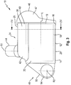
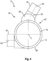
- the in the Fig. 3 and 4 illustrated exhaust treatment assembly 10 differs from the above-described exhaust treatment arrangement essentially in that the first exhaust guide assembly 24 only the two flow guide elements 26, 46 includes.
- the first flow guide element 26 is, preferably along the outer side 22 of the housing 12, directly on the outer peripheral surface 28 materially, for example by welding, so that the first Strömungsweg Scheme 38 by the first flow guide member 26 and a peripheral portion of the housing 12 is limited.
- the flow guide elements, the flow guide tubes and the housing may be preferably constructed of sheet metal material, which on the one hand easy formability, on the other hand, the ability to connect these components by material closure, guaranteed. At the same time the risk of damage to the same by overheating is almost impossible when building these components from sheet metal material.
Landscapes
- Engineering & Computer Science (AREA)
- Chemical & Material Sciences (AREA)
- Combustion & Propulsion (AREA)
- Mechanical Engineering (AREA)
- General Engineering & Computer Science (AREA)
- Chemical Kinetics & Catalysis (AREA)
- Health & Medical Sciences (AREA)
- Toxicology (AREA)
- Biomedical Technology (AREA)
- Environmental & Geological Engineering (AREA)
- Analytical Chemistry (AREA)
- General Chemical & Material Sciences (AREA)
- Oil, Petroleum & Natural Gas (AREA)
- Exhaust Gas After Treatment (AREA)
- Processes For Solid Components From Exhaust (AREA)
- Exhaust Silencers (AREA)
Abstract
Description
- Die vorliegende Erfindung betrifft eine Abgasbehandlungsanordnung, die in einer Abgasanlage einer Brennkraftmaschine eines Fahrzeugs eingesetzt werden kann, um den Schadstoffanteil in dem von der Brennkraftmaschine ausgestoßenen Abgas zu mindern. Eine derartige Abgasbehandlungsanordnung umfasst eine Abgasbehandlungseinheit, die beispielsweise eine Katalysatorbaugruppe oder/und eine Partikelfilterbaugruppe umfassen kann.
- Bei derartigen Abgasbehandlungsanordnungen besteht grundsätzlich ein Problem darin, dass für eine immer bessere Abgasbehandlung das Behandlungsvolumen, also insbesondere das Volumen der Abgasbehandlungseinheit, vergrößert werden soll, während andererseits der in Fahrzeugen zur Verfügung stehende Bauraum für derartige Abgasbehandlungsanordnungen abnimmt.
- Es ist die Aufgabe der vorliegenden Erfindung, eine Abgasbehandlungsanordnung, insbesondere für eine Abgasanlage einer Brennkraftmaschine eines Fahrzeugs, bereitzustellen, welche bei kompakter Bauart ein großes Behandlungsvolumen für diese durchströmendes Abgas bereitstellt.
- Erfindungsgemäß wird diese Aufgabe gelöst durch eine Abgasbehandlungsanordnung, insbesondere für eine Abgasanlage einer Brennkraftmaschine eines Fahrzeugs, umfassend ein in Richtung einer Gehäuselängsachse langgestrecktes Gehäuse, eine in dem Gehäuse angeordnete Abgasbehandlungseinheit sowie wenigstens eine mit einem axial offenen axialen Endbereich des Gehäuses in Strömungsverbindung stehende erste Abgasführungsanordnung, wobei die erste Abgasführungsanordnung einen entlang einer Außenseite des Gehäuses führenden ersten Strömungswegbereich sowie einen den ersten Strömungswegbereich mit dem axial offenen axialen Endbereich des Gehäuses verbindenden zweiten Strömungswegbereich bereitstellt.
- Da bei dem erfindungsgemäßen Aufbau einer Abgasbehandlungsanordnung das Abgas zu oder von der im Gehäuse angeordneten Abgasbehandlungseinheit bereichsweise entlang der Außenseite des Gehäuses geführt wird, kann das im Inneren des Gehäuses bereitgestellte Volumen im Wesentlichen vollständig für die Abgasbehandlungseinheit genutzt werden.
- Eine kompakte Bauart wird dadurch begünstigt, dass der erste Strömungswegbereich im Wesentlichen in Richtung der Gehäuselängsachse entlang der Außenseite des Gehäuses geführt ist, oder/und dass der erste Strömungswegbereich einen im axialen Bereich des axial offenen axialen Endbereichs des Gehäuses angeordneten ersten axialen Endbereich oder/und einen axial im Bereich eines anderen axialen Endbereichs des Gehäuses angeordneten zweiten axialen Endbereich aufweist.
- Um mit einfachen Mitteln die Führung von Abgas entlang der Außenseite des Gehäuses erreichen zu können, wird vorgeschlagen, dass die Abgasführungsanordnung ein an der Außenseite des Gehäuses angeordnetes erstes Abgasführungselement umfasst, wobei der erste Strömungswegbereich durch das erste Abgasführungselement wenigstens bereichsweise begrenzt ist. Es ist hier darauf hinzuweisen, dass das Anordnen eines Abgasführungselements an der Außenseite des Gehäuses nicht notwendigerweise bedeutet, dass dieses Abgasführungselement am Gehäuse selbst festgelegt ist oder mit diesem in Kontakt steht.
- Bei einer besonders kompakten Bauart kann vorgesehen sein, dass das erste Abgasführungselement an der Außenseite des Gehäuses festgelegt ist, und dass der erste Strömungswegbereich im Wesentlichen durch das erste Abgasführungselement und das Gehäuse begrenzt ist.
- Bei einer insbesondere hinsichtlich der thermischen Belastung des Gehäuses und der darin angeordneten Abgasbehandlungseinheit vorteilhaften Ausgestaltungsvariante kann an der Außenseite des Gehäuses ein zweites Abgasführungselement festgelegt sein, wobei das erste Abgasführungselement an dem zweiten Abgasführungselement oder/und der Außenseite des Gehäuses festgelegt ist und der erste Strömungswegbereich im Wesentlichen durch das erste Abgasführungselement und das zweite Abgasführungselement begrenzt ist.
- Um in einfacher und kompakter Weise eine Strömungsverbindung vom ersten Strömungswegbereich in das Gehäuse bereitstellen zu können, wird vorgeschlagen, dass ein den axial offenen axialen Endbereich des Gehäuses abschließendes und den zweiten Strömungswegbereich wenigstens bereichsweise begrenzendes, vorzugsweise im Wesentlichen haubenartiges drittes Strömungsführungselement vorgesehen ist.
- Zur Verbindung der beiden Strömungswegbereiche miteinander kann das dritte Strömungsführungselement in einem Umfangsbereich des Gehäuses zur Verbindung des zweiten Strömungswegbereichs mit dem ersten axialen Endbereich des ersten Strömungswegbereichs nach radial außen über das Gehäuse hervorstehen. Insbesondere kann dabei vorgesehen sein, dass das dritte Abgasführungselement das erste Abgasführungselement und den axial offenen axialen Endbereich des Gehäuses radial überdeckt.
- Zur Verbindung der Abgasbehandlungsanordnung mit daran anschließenden Systembereichen einer Abgasanlage wird vorgeschlagen, dass ein im zweiten axialen Endbereich des ersten Strömungswegbereichs in den ersten Strömungswegbereich einmündendes Strömungsführungsrohr vorgesehen ist.
- Um eine Durchströmbarkeit des Gehäuses zu gewährleisten, kann vorgesehen sein, dass das Gehäuse zwei axial offene axiale Endbereiche aufweist, und dass in Zuordnung zu wenigstens einem der beiden axialen Endbereiche des Gehäuses eine mit diesem axialen Endbereich in Strömungsverbindung stehende erste Abgasführungsanordnung vorgesehen ist.
- In Zuordnung zu einem der beiden axialen Endbereiche des Gehäuses kann eine zweite Abgasführungsanordnung vorgesehen sein, wobei die zweite Abgasführungsanordnung ein diesen axialen Endbereich des Gehäuses abschließendes, vorzugsweise im Wesentlichen trichterartiges viertes Strömungsführungselement umfassen kann. Dabei kann beispielsweise die erste Abgasführungsanordnung stromaufwärts der Abgasbehandlungseinheit angeordnet sein, und die zweite Abgasführungsanordnung kann stromabwärts der Abgasbehandlungseinheit angeordnet sein. Die Strömungsrichtung kann auch umgekehrt sein, so dass die erste Abgasführungsanordnung stromabwärts der Abgasbehandlungseinheit angeordnet ist und die zweite Abgasführungsanordnung stromaufwärts der Abgasbehandlungseinheit angeordnet ist.
- Für einen hinsichtlich der Durchströmung des Gehäuses im Wesentlichen symmetrischen Aufbau wird vorgeschlagen, dass in Zuordnung zu jedem der axialen Endbereiche des Gehäuses jeweils eine mit diesem in Strömungsverbindung stehende erste Abgasführungsanordnung vorgesehen ist.
- Um eine effiziente Abgasreinigung bewirken zu können, wird ferner vorgeschlagen, dass die Abgasbehandlungseinheit eine Katalysatorbaugruppe oder/und eine Partikelfilterbaugruppe umfasst.
- Die Erfindung betrifft ferner eine Abgasanlage für eine Brennkraftmaschine eines Fahrzeugs, umfassend eine in einer Abgasströmungsrichtung durchströmbare erfindungsgemäße Abgasbehandlungsanordnung.
- Die vorliegende Erfindung wird nachfolgend mit Bezug auf die beiliegenden Figuren detailliert beschrieben. Es zeigt:
- Fig. 1
- eine Seitenansicht einer Abgasbehandlungsanordnung;
- Fig. 2
- eine Darstellung der Abgasbehandlungsanordnung der
Fig. 1 , geschnitten längs einer Linie II-II inFig. 1 ; - Fig. 3
- eine der
Fig. 1 entsprechende Ansicht einer alternativen Ausgestaltungsart; - Fig. 4
- eine Darstellung der Abgasbehandlungsanordnung der
Fig. 2 , geschnitten längs einer Linie IV-IV inFig. 3 . - Die
Fig. 1 und2 zeigen eine erste Ausgestaltungsform einer allgemein mit 10 bezeichneten und in eine Abgasanlage einer Brennkraftmaschine eines Fahrzeugs integrierbare Abgasbehandlungsanordnung. Die Abgasbehandlungsanordnung 10 umfasst ein in Richtung einer Gehäuselängsachse L langgestrecktes, rohrartiges, im Wesentlichen zylindrisches Gehäuse 12. An seinen beiden axialen Endbereichen 14, 16 ist das Gehäuse 12 in Richtung der Gehäuselängsachse L grundsätzlich axial offen. Im Inneren des Gehäuses 12 ist eine allgemein mit 18 bezeichnete Abgasbehandlungseinheit angeordnet, welche beispielsweise eine Katalysatorbaugruppe oder/und eine Partikelfilterbaugruppe umfassen kann. Die Abgasbehandlungseinheit 18 kann beispielsweise unter Zwischenlagerung einer diese an der Außenseite umgebenden, aus Fasermaterial aufgebauten Matte in dem Gehäuse 12 gehalten sein, so dass eine Anströmseite 19 der Abgasbehandlungseinheit 18 im Bereich des axialen Endbereichs 16 des Gehäuses 12 liegt und eine Abströmseite 20 im Bereich des axialen Endbereichs 14 des Gehäuses 12 positioniert ist. - An einer Außenseite 22 des Gehäuses 12 ist eine allgemein mit 24 bezeichnete erste Abgasführungsanordnung vorgesehen, über welche von einer Brennkraftmaschine ausgestoßenes Abgas in das Innere des Gehäuses 12 eingeleitet wird. Die erste Abgasführungsanordnung 24 umfasst ein an der Außenseite 22 des Gehäuses 12 angeordnetes, im Wesentlichen in der Richtung der Gehäuselängsachse L sich erstreckendes, halbschalenartiges erstes Abgasführungselement 26. Die erste Abgasführungsanordnung 24 umfasst ferner ein an der Außenseite 22 des Gehäuses 12 angeordnetes und an eine Außenumfangsfläche 28 des Gehäuses 12 vorzugsweise materialschlüssig, beispielsweise durch Verschweißung, angebundenes zweites Abgasführungselement 30. Das zweite Abgasführungselement 30 weist in einem in Umfangsrichtung zentralen Bereich einen konkav bzw. schalenartig gewölbten Bereich 32 und in Umfangsrichtung daran anschließend jeweils Schenkelbereiche 34, 36 auf, mit welchen dieses an der Außenumfangsfläche 28 des Gehäuses 12 festgelegt ist. An diesen Schenkelbereichen 34, 36 ist das erste Abgasführungselement 26 vorzugsweise materialschlüssig, beispielsweise durch Verschweißung, festgelegt, so dass die beiden Abgasführungselement 26, 30 zusammen einen entlang der Außenseite 22 im Wesentlichen in Richtung der Gehäuselängsachse L sich erstreckenden ersten Strömungswegbereich 38 begrenzen. Ein erster axialer Endbereich 40 des ersten Strömungswegbereichs 38 liegt axial im Bereich des axialen Endbereichs 16 des Gehäuses 12. Ein zweiter axialer Endbereich 42 des ersten Strömungswegbereichs 38 liegt axial im Bereich des axialen Endbereichs 14 des Gehäuses 12. Im Bereich dieses zweiten axialen Endbereichs 42 mündet ein Strömungsführungsrohr 44 in den ersten Strömungswegbereich 38 ein, wobei eine Längsachse R1 des Strömungsführungsrohrs 44 beispielsweise im Wesentlichen orthogonal zur Erstreckungsrichtung des ersten Strömungswegbereichs 38 entlang der Außenseite 22 des Gehäuses 12 stehen kann. Alternativ kann die Längsachse R1 auch unter einem von 90° verschiedenen Winkel bezüglich der Erstreckungsrichtung des ersten Strömungswegbereichs 38 angeordneten sein oder derart, dass das Strömungsführungsrohr 44 den Strömungswegbereich 38 axial fortsetzt.
- Durch das Bereitstellen der beiden Strömungsführungselemente 26, 30, welche zusammen im Wesentlichen den ersten Strömungswegbereich begrenzen, wird das in Richtung zum Gehäuse 12 geförderte Abgas entlang der Außenseite 22 des Gehäuses 12 ohne wesentlichen thermischen Kontakt mit diesem geleitet, so dass eine übermäßige thermische Belastung der Abgasbehandlungseinheit 18 in diesem Umfangsbereich vermieden werden kann.
- Am axialen Endbereich 16 des Gehäuses 12 ist ein im Wesentlichen kappenartig oder haubenartig ausgebildetes drittes Strömungsführungselement 46 angeordnet. Das dritte Strömungsführungselemente 46 überdeckt den axialen Endbereich 16 des Gehäuses 12 und den ersten axialen Endbereich des ersten Strömungswegbereichs 38 bzw. die beiden Strömungsführungselemente 26, 30 in diesem Bereich und stellt somit einen gasdichten Abschluss sowie einen zweiten Strömungswegbereich 47 zur Herstellung einer Strömungsverbindung zwischen dem ersten Strömungswegbereich 38 und dem axial offenen axialen Endbereich 16 des Gehäuses 12 bereit. Wie durch einen Strömungspfeil P1 angedeutet, wird das den ersten Strömungswegbereich 38 durchströmende und diesen an seinem ersten axialen Endbereich 40 verlassende Abgas näherungsweise um 180° umgelenkt, so dass es auf die Anströmseite 19 der Abgasbehandlungsanordnung 18 zu strömt. Das dritte Abgasführungselement 46 kann mit einem das Gehäuse 12 und die beiden Strömungsführungselemente 26, 30 übergreifenden zylindrischen Abschnitt 48 an der Außenseite dieser Bauteile vorzugsweise materialschlüssig, beispielsweise durch Verschweißung, festgelegt sein.
- Im Bereich des axialen Endbereichs 14 des Gehäuses 12 ist ein eine zweite Abgasführungsanordnung 49 bereitstellendes viertes Strömungsführungselement 50 am Gehäuse 12 vorzugsweise materialschlüssig, beispielsweise durch Verschweißung, festgelegt. Ein im Wesentlichen zylindrischer Abschnitt 52 des beispielsweise im Wesentlichen haubenartig geformten vierten Strömungsführungselements 50 kann in den axialen Endbereichs 14 des Gehäuses 12 eingesetzt und daran festgelegt sein. Ein Strömungsführungsrohr 54 mündet in das vierte Strömungsführungselement 50 ein, wobei eine Längsachse R2 des Strömungsführungsrohrs 54 zur Richtung der Gehäuselängsachse L näherungsweise orthogonal stehen kann, so dass vorzugsweise die beiden Längsachsen R1, R2 der Strömungsführungsrohre 44, 54 zueinander angewinkelt sind. Das Gehäuse 12 an dessen axialen Endbereich 14 verlassendes Abgas wird im vierten Strömungsführungselement 50, wie durch einen Strömungspfeil P2 angedeutet, näherungsweise um 90° umgelenkt, bevor es in das Strömungsführungsrohr 54 eintritt. Auch das Strömungsführungsrohr 54 könnte derart angeordnet sein, dass eine Umlenkung um einen von 90° verschiedenen Winkel erfolgt oder im Wesentlichen keine Umlenkung erfolgt, so dass das Strömungsführungsrohr 54 die dieses durchströmenden Abgase im Wesentlichen in Richtung der Gehäuselängsachse L weiterleitet.
- Mit dem vorangehend beschriebenen Aufbau wird eine kompakte Bauweise der Abgasbehandlungsanordnung 10 erhalten, bei welcher gleichwohl ein vergleichsweise großes Volumen für die Abgasbehandlungseinheit 18 bereitgestellt ist. Die Erstreckungsrichtung der Längsachsen R1, R2 kann einerseits durch entsprechende Ausgestaltung des ersten Strömungsführungselements 26, andererseits durch Auswahl der Positionierung des vierten Strömungsführungselements 50 in großen Winkelbereichen frei gewählt werden, so dass eine Anpassung des Aufbaus an verschiedenste Abgasanlagen leicht möglich ist.
- Ferner kann auch in Zuordnung zum axialen Endbereich 14 des Gehäuses 12 eine der ersten Abgasführungsanordnung 24 mit den Strömungsführungselementen 26, 30, 46 entsprechende Anordnung vorgesehen sein. Weiter kann die Strömungsrichtung, in welcher Abgas das Gehäuse 12 und die darin angeordnete Abgasbehandlungseinheit 18 durchströmt, bezüglich der vorangehend beschriebenen Strömungsrichtung umgekehrt sein, so dass Abgas im Bereich des axialen Endbereichs 14 in das Gehäuse 12 eintritt und dieses im Bereich des axialen Endbereichs 16 verlässt.
- Die in den
Fig. 3 und4 dargestellte Abgasbehandlungsanordnung 10 unterscheidet sich von der vorangehend beschriebenen Abgasbehandlungsanordnung im Wesentlichen dadurch, dass die erste Abgasführungsanordnung 24 nur die beiden Strömungsführungselemente 26, 46 umfasst. Das erste Strömungsführungselement 26 ist, sich entlang der Außenseite 22 des Gehäuses 12 erstreckend, direkt an der Außenumfangsfläche 28 vorzugsweise materialschlüssig, beispielsweise durch Verschweißung, festgelegt, so dass der erste Strömungswegbereich 38 durch das erste Strömungsführungselement 26 und einen Umfangsbereich des Gehäuses 12 begrenzt ist. Somit kann bei geringerer Anzahl an Bauteilen eine noch kompaktere Bauart erreichen - Es ist abschließend darauf hinzuweisen, dass bei der vorangehend beschriebenen Abgasbehandlungsanordnung die Strömungsführungselemente, die Strömungsführungsrohre und das Gehäuse vorzugsweise aus Blechmaterial aufgebaut sein können, was einerseits eine leichte Umformbarkeit, andererseits die Möglichkeit, diese Bauteile durch Materialschluss miteinander zu verbinden, gewährleistet. Gleichzeitig ist bei Aufbau dieser Bauteile aus Blechmaterial die Gefahr einer Beschädigung derselben durch Überhitzung nahezu ausgeschlossen.
Claims (16)
- Abgasbehandlungsanordnung, insbesondere für eine Abgasanlage einer Brennkraftmaschine eines Fahrzeugs, umfassend ein in Richtung einer Gehäuselängsachse (L) langgestrecktes Gehäuse (12), eine in dem Gehäuse (12) angeordnete Abgasbehandlungseinheit (18) sowie wenigstens eine mit einem axial offenen axialen Endbereich (16) des Gehäuses (12) in Strömungsverbindung stehende erste Abgasführungsanordnung (24), wobei die erste Abgasführungsanordnung (24) einen entlang einer Außenseite (22) des Gehäuses (12) führenden ersten Strömungswegbereich (38) sowie einen den ersten Strömungswegbereich (38) mit dem axial offenen axialen Endbereich (16) des Gehäuses (12) verbindenden zweiten Strömungswegbereich (47) bereitstellt.
- Abgasbehandlungsanordnung nach Anspruch 1, dadurch gekennzeichnet, dass der erste Strömungswegbereich (38) im Wesentlichen in Richtung der Gehäuselängsachse (L) entlang der Außenseite (22) des Gehäuses (12) geführt ist, oder/und dass der erste Strömungswegbereich (38) einen im axialen Bereich des axial offenen axialen Endbereichs (16) des Gehäuses (12) angeordneten ersten axialen Endbereich (40) oder/und einen axial im Bereich eines anderen axialen Endbereichs (14) des Gehäuses (12) angeordneten zweiten axialen Endbereich (42) aufweist.
- Abgasbehandlungsanordnung nach Anspruch 1 oder 2, dadurch gekennzeichnet, dass die Abgasführungsanordnung (24) ein an der Außenseite (22) des Gehäuses (12) angeordnetes erstes Abgasführungselement (26) umfasst, wobei der erste Strömungswegbereich (38) durch das erste Abgasführungselement (26) wenigstens bereichsweise begrenzt ist.
- Abgasbehandlungsanordnung noch Anspruch 3, dadurch gekennzeichnet, dass das erste Abgasführungselement (26) an der Außenseite (22) des Gehäuses (12) festgelegt ist, und dass der erste Strömungswegbereich (38) im Wesentlichen durch das erste Abgasführungselement (26) und das Gehäuse (12) begrenzt ist.
- Abgasbehandlungsanordnung nach Anspruch 3, dadurch gekennzeichnet, dass an der Außenseite (22) des Gehäuses (12) ein zweites Abgasführungselement (30) festgelegt ist, dass das erste Abgasführungselement (26) an dem zweiten Abgasführungselement (30) oder/und der Außenseite (22) des Gehäuses (12) festgelegt ist, und dass der erste Strömungswegbereich (38) im Wesentlichen durch das erste Abgasführungselement (26) und das zweite Abgasführungselement (30) begrenzt ist.
- Abgasbehandlungsanordnung nach einem der vorangehenden Ansprüche, dadurch gekennzeichnet, dass ein den axial offenen axialen Endbereich (16) des Gehäuses (12) abschließendes und den zweiten Strömungswegbereich (47) wenigstens bereichsweise begrenzendes, vorzugsweise im Wesentlichen haubenartiges drittes Strömungsführungselement (46) vorgesehen ist.
- Abgasbehandlungsanordnung nach Anspruch 2 und Anspruch 6, dadurch gekennzeichnet, dass das dritte Strömungsführungselement (46) in einem Umfangsbereich des Gehäuses (12) zur Verbindung des zweiten Strömungswegbereichs (47) mit dem ersten axialen Endbereich (40) des ersten Strömungswegbereichs (38) nach radial außen über das Gehäuse (12) hervorsteht.
- Abgasbehandlungsanordnung nach Anspruch 7 und Anspruch 3 oder 4, dadurch gekennzeichnet, dass das dritte Abgasführungselement (46) das erste Abgasführungselement (26) und den axial offenen axialen Endbereich (16) des Gehäuses (12) radial überdeckt.
- Abgasbehandlungsanordnung nach Anspruch 2 oder einem der Ansprüche 3-8, sofern auf Anspruch 2 rückbezogen, dadurch gekennzeichnet, dass ein im zweiten axialen Endbereich (42) des ersten Strömungswegbereichs (38) in den ersten Strömungswegbereich (38) einmündendes Strömungsführungsrohr (44) vorgesehen ist.
- Abgasbehandlungsanordnung nach einem der vorangehenden Ansprüche, dadurch gekennzeichnet, dass das Gehäuse (12) zwei axial offene axiale Endbereiche (14, 16) aufweist, und dass in Zuordnung zu wenigstens einem der beiden axialen Endbereiche (14, 16) des Gehäuses (12) eine mit diesem axialen Endbereich (14) in Strömungsverbindung stehende erste Abgasführungsanordnung (24) vorgesehen ist.
- Abgasbehandlungsanordnung nach Anspruch 10, dadurch gekennzeichnet, dass in Zuordnung zu einem der beiden axialen Endbereiche (14,16) des Gehäuses (12) eine zweite Abgasführungsanordnung (49) vorgesehen ist, wobei die zweite Abgasführungsanordnung (49) ein diesen axialen Endbereich (14) des Gehäuses (12) abschließendes, vorzugsweise im Wesentlichen trichterartiges viertes Strömungsführungselement (50) umfasst.
- Abgasbehandlungsanordnung nach Anspruch 10 oder 11, dadurch gekennzeichnet, dass die erste Abgasführungsanordnung (24) stromaufwärts der Abgasbehandlungseinheit (18) angeordnet ist, und dass die zweite Abgasführungsanordnung (49) stromabwärts der Abgasbehandlungseinheit (18) angeordnet ist.
- Abgasbehandlungsanordnung nach Anspruch 10 oder 11, dadurch gekennzeichnet, dass die erste Abgasführungsanordnung (24) stromabwärts der Abgasbehandlungseinheit (18) angeordnet ist, und dass die zweite Abgasführungsanordnung (49) stromaufwärts der Abgasbehandlungseinheit (18) angeordnet ist.
- Abgasbehandlungsanordnung nach einem der Ansprüche 1-10, dadurch gekennzeichnet, dass in Zuordnung zu jedem der axialen Endbereiche (14, 16) des Gehäuses (12) jeweils eine mit diesem in Strömungsverbindung stehende erste Abgasführungsanordnung (24) vorgesehen ist.
- Abgasbehandlungsanordnung nach einem der vorangehenden Ansprüche, dadurch gekennzeichnet, dass die Abgasbehandlungseinheit (18) eine Katalysatorbaugruppe oder/und eine Partikelfilterbaugruppe umfasst.
- Abgasanlage für eine Brennkraftmaschine eines Fahrzeugs, umfassend eine in einer Abgasströmungsrichtung durchströmbare Abgasbehandlungsanordnung (10) nach einem der vorangehenden Ansprüche.
Applications Claiming Priority (1)
| Application Number | Priority Date | Filing Date | Title |
|---|---|---|---|
| DE102016122769.2A DE102016122769A1 (de) | 2016-11-25 | 2016-11-25 | Abgasbehandlungsanordnung |
Publications (2)
| Publication Number | Publication Date |
|---|---|
| EP3327261A1 true EP3327261A1 (de) | 2018-05-30 |
| EP3327261B1 EP3327261B1 (de) | 2020-06-03 |
Family
ID=60269739
Family Applications (1)
| Application Number | Title | Priority Date | Filing Date |
|---|---|---|---|
| EP17200491.3A Active EP3327261B1 (de) | 2016-11-25 | 2017-11-08 | Abgasbehandlungsanordnung |
Country Status (5)
| Country | Link |
|---|---|
| US (1) | US10113472B2 (de) |
| EP (1) | EP3327261B1 (de) |
| JP (1) | JP6494731B2 (de) |
| CN (1) | CN108104906B (de) |
| DE (1) | DE102016122769A1 (de) |
Families Citing this family (1)
| Publication number | Priority date | Publication date | Assignee | Title |
|---|---|---|---|---|
| JP6956436B1 (ja) * | 2020-12-24 | 2021-11-02 | 株式会社大都技研 | 遊技台 |
Citations (7)
| Publication number | Priority date | Publication date | Assignee | Title |
|---|---|---|---|---|
| WO2004063540A1 (de) * | 2003-01-14 | 2004-07-29 | Emitec Gesellschaft Für Emissionstechnologie Mbh | Platzsparende abgasnachbehandlungseinheit mit ineinanderliegenden hin- und rückströmbereichen bei gleichseitigem gasein- und -austritt |
| EP1736645A1 (de) * | 2004-03-25 | 2006-12-27 | Nissan Diesel Motor Co., Ltd. | Dämpfervorrichtung mit abgasreinigungsfunktion |
| EP1857651A2 (de) * | 2006-05-19 | 2007-11-21 | J. Eberspächer GmbH & Co. KG | Abgasnachbehandlungseinrichtung für eine Brennkraftmaschine |
| JP2008215286A (ja) * | 2007-03-07 | 2008-09-18 | Hino Motors Ltd | 排気浄化装置 |
| EP2233709A1 (de) * | 2009-03-26 | 2010-09-29 | J. Eberspächer GmbH & Co. KG | Abgasbehandlungseinrichtung |
| WO2014167353A1 (en) * | 2013-04-11 | 2014-10-16 | Perkins Engines Company Limited | Flowhood and emissions cleaning module |
| DE102014108877A1 (de) * | 2014-06-25 | 2015-12-31 | Twintec Technologie Gmbh | Vorrichtung und Verfahren zur Erzeugung von Ammoniak zur Abgasnachbehandlung |
Family Cites Families (10)
| Publication number | Priority date | Publication date | Assignee | Title |
|---|---|---|---|---|
| US4663934A (en) * | 1985-04-01 | 1987-05-12 | Arvin Industries, Inc. | Manifold exhaust processor |
| US6824743B1 (en) * | 2000-05-24 | 2004-11-30 | Fleet Guard, Inc. | Space efficient exhaust aftertreatment filter |
| JP4886547B2 (ja) * | 2007-02-23 | 2012-02-29 | 日野自動車株式会社 | 排気浄化装置 |
| JP5215789B2 (ja) * | 2008-09-18 | 2013-06-19 | ヤンマー株式会社 | 排気ガス浄化装置 |
| JP5185751B2 (ja) * | 2008-09-18 | 2013-04-17 | ヤンマー株式会社 | 排気ガス浄化装置 |
| US9422845B2 (en) * | 2012-01-03 | 2016-08-23 | Volvo Lastvagnar Ab | Method and arrangement for cleaning a particle filter |
| GB2510888A (en) * | 2013-02-18 | 2014-08-20 | Ford Global Tech Llc | A catalytic converter assembly |
| JP5825726B2 (ja) * | 2014-04-10 | 2015-12-02 | ヤンマー株式会社 | 排気ガス浄化装置 |
| EP2960456B1 (de) * | 2014-06-27 | 2017-04-12 | Volvo Car Corporation | winkelförmige und kompakte Abgasnachbehandlungseinrichtung |
| JP6498993B2 (ja) * | 2015-04-01 | 2019-04-10 | 日野自動車株式会社 | 排気浄化装置 |
-
2016
- 2016-11-25 DE DE102016122769.2A patent/DE102016122769A1/de not_active Withdrawn
-
2017
- 2017-10-31 CN CN201711053711.5A patent/CN108104906B/zh active Active
- 2017-11-08 EP EP17200491.3A patent/EP3327261B1/de active Active
- 2017-11-21 US US15/819,354 patent/US10113472B2/en active Active
- 2017-11-24 JP JP2017225640A patent/JP6494731B2/ja active Active
Patent Citations (7)
| Publication number | Priority date | Publication date | Assignee | Title |
|---|---|---|---|---|
| WO2004063540A1 (de) * | 2003-01-14 | 2004-07-29 | Emitec Gesellschaft Für Emissionstechnologie Mbh | Platzsparende abgasnachbehandlungseinheit mit ineinanderliegenden hin- und rückströmbereichen bei gleichseitigem gasein- und -austritt |
| EP1736645A1 (de) * | 2004-03-25 | 2006-12-27 | Nissan Diesel Motor Co., Ltd. | Dämpfervorrichtung mit abgasreinigungsfunktion |
| EP1857651A2 (de) * | 2006-05-19 | 2007-11-21 | J. Eberspächer GmbH & Co. KG | Abgasnachbehandlungseinrichtung für eine Brennkraftmaschine |
| JP2008215286A (ja) * | 2007-03-07 | 2008-09-18 | Hino Motors Ltd | 排気浄化装置 |
| EP2233709A1 (de) * | 2009-03-26 | 2010-09-29 | J. Eberspächer GmbH & Co. KG | Abgasbehandlungseinrichtung |
| WO2014167353A1 (en) * | 2013-04-11 | 2014-10-16 | Perkins Engines Company Limited | Flowhood and emissions cleaning module |
| DE102014108877A1 (de) * | 2014-06-25 | 2015-12-31 | Twintec Technologie Gmbh | Vorrichtung und Verfahren zur Erzeugung von Ammoniak zur Abgasnachbehandlung |
Also Published As
| Publication number | Publication date |
|---|---|
| JP2018084235A (ja) | 2018-05-31 |
| DE102016122769A1 (de) | 2018-05-30 |
| EP3327261B1 (de) | 2020-06-03 |
| JP6494731B2 (ja) | 2019-04-03 |
| US10113472B2 (en) | 2018-10-30 |
| US20180149069A1 (en) | 2018-05-31 |
| CN108104906A (zh) | 2018-06-01 |
| CN108104906B (zh) | 2021-02-05 |
Similar Documents
| Publication | Publication Date | Title |
|---|---|---|
| EP2161423B1 (de) | Abgasanlage für Dieselfahrzeuge mit einem SCR-Katalysator | |
| EP2233709B1 (de) | Abgasbehandlungseinrichtung | |
| DE102013210799B4 (de) | Abgasanlage einer Brennkraftmaschine | |
| DE19914426C2 (de) | Doppelwandiges Endrohr für ein Abgasrohr einer Abgasanlage eines Kraftfahrzeuges | |
| DE102008031136B4 (de) | Abgasbehandlungseinrichtung | |
| DE102011089969B4 (de) | Abgasbehandlungsvorrichtung | |
| EP3158175B1 (de) | Mischvorrichtung eines abgasreinigungssystems einer kraftfahrzeug-brennkraftmaschine | |
| DE102010021040A1 (de) | Mischer und Abgasanlage | |
| EP2606233B1 (de) | VENTIL EINER KOLBENPUMPE MIT EINEM SCHLIEßKÖRPER | |
| EP3447378B1 (de) | Fahrzeugheizgerät | |
| EP3400155A2 (de) | Geräuschdämpfer für ein druckluftsystem eines fahrzeugs, insbesondere eines nutzfahrzeugs | |
| DE102015104540B3 (de) | Mischvorrichtung | |
| EP4048426A1 (de) | Behandlungsvorrichtung zur behandlung von insbesondere flüssigen fluiden sowie behandlungseinheit und anschlusskopf für eine behandlungsvorrichtung | |
| EP3412879B1 (de) | Abgasnachbehandlungsvorrichtung einer brennkraftmaschine eines kraftfahrzeugs | |
| EP2553224B1 (de) | Kupplungseinrichtung, kurbelgehäuseentlüftungseinrichtung und frischluftanlage | |
| EP3252315B1 (de) | Seitenkanalgebläse, insbesondere für ein fahrzeugheizgerät | |
| EP3597997B1 (de) | Fahrzeugheizgerät | |
| DE102013106075A1 (de) | Vorrichtung zum schwingungsentkoppelten Verbinden zweier Einrichtungen einer Abgasanlage | |
| EP3327261B1 (de) | Abgasbehandlungsanordnung | |
| EP3851646B1 (de) | Gas/gas-mischer zum einleiten von gas in den abgasstrom einer brennkraftmaschine | |
| DE102019104772A1 (de) | Abgasanlage | |
| DE102015102611A1 (de) | Abgasführungssystem für eine Brennkraftmaschine | |
| EP1437489B2 (de) | Abgasanlage | |
| DE102018107766A1 (de) | Abgasanlage und Mischerbaugruppe für eine Abgasanlage | |
| EP4223398B1 (de) | Mischbaugruppe für eine abgasanlage einer brennkraftmaschine |
Legal Events
| Date | Code | Title | Description |
|---|---|---|---|
| PUAI | Public reference made under article 153(3) epc to a published international application that has entered the european phase |
Free format text: ORIGINAL CODE: 0009012 |
|
| STAA | Information on the status of an ep patent application or granted ep patent |
Free format text: STATUS: THE APPLICATION HAS BEEN PUBLISHED |
|
| AK | Designated contracting states |
Kind code of ref document: A1 Designated state(s): AL AT BE BG CH CY CZ DE DK EE ES FI FR GB GR HR HU IE IS IT LI LT LU LV MC MK MT NL NO PL PT RO RS SE SI SK SM TR |
|
| AX | Request for extension of the european patent |
Extension state: BA ME |
|
| STAA | Information on the status of an ep patent application or granted ep patent |
Free format text: STATUS: REQUEST FOR EXAMINATION WAS MADE |
|
| 17P | Request for examination filed |
Effective date: 20181016 |
|
| RBV | Designated contracting states (corrected) |
Designated state(s): AL AT BE BG CH CY CZ DE DK EE ES FI FR GB GR HR HU IE IS IT LI LT LU LV MC MK MT NL NO PL PT RO RS SE SI SK SM TR |
|
| STAA | Information on the status of an ep patent application or granted ep patent |
Free format text: STATUS: EXAMINATION IS IN PROGRESS |
|
| 17Q | First examination report despatched |
Effective date: 20190102 |
|
| GRAP | Despatch of communication of intention to grant a patent |
Free format text: ORIGINAL CODE: EPIDOSNIGR1 |
|
| STAA | Information on the status of an ep patent application or granted ep patent |
Free format text: STATUS: GRANT OF PATENT IS INTENDED |
|
| INTG | Intention to grant announced |
Effective date: 20200206 |
|
| GRAS | Grant fee paid |
Free format text: ORIGINAL CODE: EPIDOSNIGR3 |
|
| GRAA | (expected) grant |
Free format text: ORIGINAL CODE: 0009210 |
|
| STAA | Information on the status of an ep patent application or granted ep patent |
Free format text: STATUS: THE PATENT HAS BEEN GRANTED |
|
| AK | Designated contracting states |
Kind code of ref document: B1 Designated state(s): AL AT BE BG CH CY CZ DE DK EE ES FI FR GB GR HR HU IE IS IT LI LT LU LV MC MK MT NL NO PL PT RO RS SE SI SK SM TR |
|
| REG | Reference to a national code |
Ref country code: GB Ref legal event code: FG4D Free format text: NOT ENGLISH |
|
| REG | Reference to a national code |
Ref country code: AT Ref legal event code: REF Ref document number: 1277232 Country of ref document: AT Kind code of ref document: T Effective date: 20200615 Ref country code: CH Ref legal event code: EP |
|
| REG | Reference to a national code |
Ref country code: DE Ref legal event code: R096 Ref document number: 502017005528 Country of ref document: DE |
|
| REG | Reference to a national code |
Ref country code: LT Ref legal event code: MG4D |
|
| PG25 | Lapsed in a contracting state [announced via postgrant information from national office to epo] |
Ref country code: NO Free format text: LAPSE BECAUSE OF FAILURE TO SUBMIT A TRANSLATION OF THE DESCRIPTION OR TO PAY THE FEE WITHIN THE PRESCRIBED TIME-LIMIT Effective date: 20200903 Ref country code: GR Free format text: LAPSE BECAUSE OF FAILURE TO SUBMIT A TRANSLATION OF THE DESCRIPTION OR TO PAY THE FEE WITHIN THE PRESCRIBED TIME-LIMIT Effective date: 20200904 Ref country code: FI Free format text: LAPSE BECAUSE OF FAILURE TO SUBMIT A TRANSLATION OF THE DESCRIPTION OR TO PAY THE FEE WITHIN THE PRESCRIBED TIME-LIMIT Effective date: 20200603 Ref country code: SE Free format text: LAPSE BECAUSE OF FAILURE TO SUBMIT A TRANSLATION OF THE DESCRIPTION OR TO PAY THE FEE WITHIN THE PRESCRIBED TIME-LIMIT Effective date: 20200603 Ref country code: LT Free format text: LAPSE BECAUSE OF FAILURE TO SUBMIT A TRANSLATION OF THE DESCRIPTION OR TO PAY THE FEE WITHIN THE PRESCRIBED TIME-LIMIT Effective date: 20200603 |
|
| REG | Reference to a national code |
Ref country code: NL Ref legal event code: MP Effective date: 20200603 |
|
| PG25 | Lapsed in a contracting state [announced via postgrant information from national office to epo] |
Ref country code: HR Free format text: LAPSE BECAUSE OF FAILURE TO SUBMIT A TRANSLATION OF THE DESCRIPTION OR TO PAY THE FEE WITHIN THE PRESCRIBED TIME-LIMIT Effective date: 20200603 Ref country code: BG Free format text: LAPSE BECAUSE OF FAILURE TO SUBMIT A TRANSLATION OF THE DESCRIPTION OR TO PAY THE FEE WITHIN THE PRESCRIBED TIME-LIMIT Effective date: 20200903 Ref country code: RS Free format text: LAPSE BECAUSE OF FAILURE TO SUBMIT A TRANSLATION OF THE DESCRIPTION OR TO PAY THE FEE WITHIN THE PRESCRIBED TIME-LIMIT Effective date: 20200603 Ref country code: LV Free format text: LAPSE BECAUSE OF FAILURE TO SUBMIT A TRANSLATION OF THE DESCRIPTION OR TO PAY THE FEE WITHIN THE PRESCRIBED TIME-LIMIT Effective date: 20200603 |
|
| PG25 | Lapsed in a contracting state [announced via postgrant information from national office to epo] |
Ref country code: AL Free format text: LAPSE BECAUSE OF FAILURE TO SUBMIT A TRANSLATION OF THE DESCRIPTION OR TO PAY THE FEE WITHIN THE PRESCRIBED TIME-LIMIT Effective date: 20200603 Ref country code: NL Free format text: LAPSE BECAUSE OF FAILURE TO SUBMIT A TRANSLATION OF THE DESCRIPTION OR TO PAY THE FEE WITHIN THE PRESCRIBED TIME-LIMIT Effective date: 20200603 |
|
| PG25 | Lapsed in a contracting state [announced via postgrant information from national office to epo] |
Ref country code: ES Free format text: LAPSE BECAUSE OF FAILURE TO SUBMIT A TRANSLATION OF THE DESCRIPTION OR TO PAY THE FEE WITHIN THE PRESCRIBED TIME-LIMIT Effective date: 20200603 Ref country code: SM Free format text: LAPSE BECAUSE OF FAILURE TO SUBMIT A TRANSLATION OF THE DESCRIPTION OR TO PAY THE FEE WITHIN THE PRESCRIBED TIME-LIMIT Effective date: 20200603 Ref country code: EE Free format text: LAPSE BECAUSE OF FAILURE TO SUBMIT A TRANSLATION OF THE DESCRIPTION OR TO PAY THE FEE WITHIN THE PRESCRIBED TIME-LIMIT Effective date: 20200603 Ref country code: IT Free format text: LAPSE BECAUSE OF FAILURE TO SUBMIT A TRANSLATION OF THE DESCRIPTION OR TO PAY THE FEE WITHIN THE PRESCRIBED TIME-LIMIT Effective date: 20200603 Ref country code: PT Free format text: LAPSE BECAUSE OF FAILURE TO SUBMIT A TRANSLATION OF THE DESCRIPTION OR TO PAY THE FEE WITHIN THE PRESCRIBED TIME-LIMIT Effective date: 20201006 Ref country code: RO Free format text: LAPSE BECAUSE OF FAILURE TO SUBMIT A TRANSLATION OF THE DESCRIPTION OR TO PAY THE FEE WITHIN THE PRESCRIBED TIME-LIMIT Effective date: 20200603 Ref country code: CZ Free format text: LAPSE BECAUSE OF FAILURE TO SUBMIT A TRANSLATION OF THE DESCRIPTION OR TO PAY THE FEE WITHIN THE PRESCRIBED TIME-LIMIT Effective date: 20200603 |
|
| PG25 | Lapsed in a contracting state [announced via postgrant information from national office to epo] |
Ref country code: IS Free format text: LAPSE BECAUSE OF FAILURE TO SUBMIT A TRANSLATION OF THE DESCRIPTION OR TO PAY THE FEE WITHIN THE PRESCRIBED TIME-LIMIT Effective date: 20201003 Ref country code: PL Free format text: LAPSE BECAUSE OF FAILURE TO SUBMIT A TRANSLATION OF THE DESCRIPTION OR TO PAY THE FEE WITHIN THE PRESCRIBED TIME-LIMIT Effective date: 20200603 Ref country code: SK Free format text: LAPSE BECAUSE OF FAILURE TO SUBMIT A TRANSLATION OF THE DESCRIPTION OR TO PAY THE FEE WITHIN THE PRESCRIBED TIME-LIMIT Effective date: 20200603 |
|
| REG | Reference to a national code |
Ref country code: DE Ref legal event code: R097 Ref document number: 502017005528 Country of ref document: DE |
|
| PLBE | No opposition filed within time limit |
Free format text: ORIGINAL CODE: 0009261 |
|
| STAA | Information on the status of an ep patent application or granted ep patent |
Free format text: STATUS: NO OPPOSITION FILED WITHIN TIME LIMIT |
|
| PG25 | Lapsed in a contracting state [announced via postgrant information from national office to epo] |
Ref country code: DK Free format text: LAPSE BECAUSE OF FAILURE TO SUBMIT A TRANSLATION OF THE DESCRIPTION OR TO PAY THE FEE WITHIN THE PRESCRIBED TIME-LIMIT Effective date: 20200603 |
|
| 26N | No opposition filed |
Effective date: 20210304 |
|
| PG25 | Lapsed in a contracting state [announced via postgrant information from national office to epo] |
Ref country code: SI Free format text: LAPSE BECAUSE OF FAILURE TO SUBMIT A TRANSLATION OF THE DESCRIPTION OR TO PAY THE FEE WITHIN THE PRESCRIBED TIME-LIMIT Effective date: 20200603 |
|
| PG25 | Lapsed in a contracting state [announced via postgrant information from national office to epo] |
Ref country code: MC Free format text: LAPSE BECAUSE OF FAILURE TO SUBMIT A TRANSLATION OF THE DESCRIPTION OR TO PAY THE FEE WITHIN THE PRESCRIBED TIME-LIMIT Effective date: 20200603 |
|
| REG | Reference to a national code |
Ref country code: CH Ref legal event code: PL |
|
| REG | Reference to a national code |
Ref country code: DE Ref legal event code: R082 Ref document number: 502017005528 Country of ref document: DE Representative=s name: RUTTENSPERGER LACHNIT TROSSIN GOMOLL, PATENT- , DE Ref country code: DE Ref legal event code: R081 Ref document number: 502017005528 Country of ref document: DE Owner name: PUREM GMBH, DE Free format text: FORMER OWNER: EBERSPAECHER EXHAUST TECHNOLOGY GMBH & CO. KG, 66539 NEUNKIRCHEN, DE |
|
| PG25 | Lapsed in a contracting state [announced via postgrant information from national office to epo] |
Ref country code: LU Free format text: LAPSE BECAUSE OF NON-PAYMENT OF DUE FEES Effective date: 20201108 |
|
| REG | Reference to a national code |
Ref country code: BE Ref legal event code: MM Effective date: 20201130 |
|
| PG25 | Lapsed in a contracting state [announced via postgrant information from national office to epo] |
Ref country code: LI Free format text: LAPSE BECAUSE OF NON-PAYMENT OF DUE FEES Effective date: 20201130 Ref country code: CH Free format text: LAPSE BECAUSE OF NON-PAYMENT OF DUE FEES Effective date: 20201130 |
|
| REG | Reference to a national code |
Ref country code: GB Ref legal event code: 732E Free format text: REGISTERED BETWEEN 20210902 AND 20210908 |
|
| PG25 | Lapsed in a contracting state [announced via postgrant information from national office to epo] |
Ref country code: IE Free format text: LAPSE BECAUSE OF NON-PAYMENT OF DUE FEES Effective date: 20201108 |
|
| PG25 | Lapsed in a contracting state [announced via postgrant information from national office to epo] |
Ref country code: TR Free format text: LAPSE BECAUSE OF FAILURE TO SUBMIT A TRANSLATION OF THE DESCRIPTION OR TO PAY THE FEE WITHIN THE PRESCRIBED TIME-LIMIT Effective date: 20200603 Ref country code: MT Free format text: LAPSE BECAUSE OF FAILURE TO SUBMIT A TRANSLATION OF THE DESCRIPTION OR TO PAY THE FEE WITHIN THE PRESCRIBED TIME-LIMIT Effective date: 20200603 Ref country code: CY Free format text: LAPSE BECAUSE OF FAILURE TO SUBMIT A TRANSLATION OF THE DESCRIPTION OR TO PAY THE FEE WITHIN THE PRESCRIBED TIME-LIMIT Effective date: 20200603 |
|
| PG25 | Lapsed in a contracting state [announced via postgrant information from national office to epo] |
Ref country code: MK Free format text: LAPSE BECAUSE OF FAILURE TO SUBMIT A TRANSLATION OF THE DESCRIPTION OR TO PAY THE FEE WITHIN THE PRESCRIBED TIME-LIMIT Effective date: 20200603 |
|
| PG25 | Lapsed in a contracting state [announced via postgrant information from national office to epo] |
Ref country code: BE Free format text: LAPSE BECAUSE OF NON-PAYMENT OF DUE FEES Effective date: 20201130 |
|
| REG | Reference to a national code |
Ref country code: AT Ref legal event code: MM01 Ref document number: 1277232 Country of ref document: AT Kind code of ref document: T Effective date: 20221108 |
|
| PG25 | Lapsed in a contracting state [announced via postgrant information from national office to epo] |
Ref country code: AT Free format text: LAPSE BECAUSE OF NON-PAYMENT OF DUE FEES Effective date: 20221108 |
|
| PGFP | Annual fee paid to national office [announced via postgrant information from national office to epo] |
Ref country code: DE Payment date: 20251118 Year of fee payment: 9 |
|
| PGFP | Annual fee paid to national office [announced via postgrant information from national office to epo] |
Ref country code: GB Payment date: 20251120 Year of fee payment: 9 |
|
| PGFP | Annual fee paid to national office [announced via postgrant information from national office to epo] |
Ref country code: FR Payment date: 20251120 Year of fee payment: 9 |