EP1437489B2 - Abgasanlage - Google Patents
Abgasanlage Download PDFInfo
- Publication number
- EP1437489B2 EP1437489B2 EP03024193A EP03024193A EP1437489B2 EP 1437489 B2 EP1437489 B2 EP 1437489B2 EP 03024193 A EP03024193 A EP 03024193A EP 03024193 A EP03024193 A EP 03024193A EP 1437489 B2 EP1437489 B2 EP 1437489B2
- Authority
- EP
- European Patent Office
- Prior art keywords
- exhaust pipe
- funnel
- monolith
- exhaust
- section
- Prior art date
- Legal status (The legal status is an assumption and is not a legal conclusion. Google has not performed a legal analysis and makes no representation as to the accuracy of the status listed.)
- Expired - Fee Related
Links
Images
Classifications
-
- F—MECHANICAL ENGINEERING; LIGHTING; HEATING; WEAPONS; BLASTING
- F01—MACHINES OR ENGINES IN GENERAL; ENGINE PLANTS IN GENERAL; STEAM ENGINES
- F01N—GAS-FLOW SILENCERS OR EXHAUST APPARATUS FOR MACHINES OR ENGINES IN GENERAL; GAS-FLOW SILENCERS OR EXHAUST APPARATUS FOR INTERNAL COMBUSTION ENGINES
- F01N13/00—Exhaust or silencing apparatus characterised by constructional features ; Exhaust or silencing apparatus, or parts thereof, having pertinent characteristics not provided for in, or of interest apart from, groups F01N1/00 - F01N5/00, F01N9/00, F01N11/00
- F01N13/18—Construction facilitating manufacture, assembly, or disassembly
- F01N13/1838—Construction facilitating manufacture, assembly, or disassembly characterised by the type of connection between parts of exhaust or silencing apparatus, e.g. between housing and tubes, between tubes and baffles
-
- F—MECHANICAL ENGINEERING; LIGHTING; HEATING; WEAPONS; BLASTING
- F01—MACHINES OR ENGINES IN GENERAL; ENGINE PLANTS IN GENERAL; STEAM ENGINES
- F01N—GAS-FLOW SILENCERS OR EXHAUST APPARATUS FOR MACHINES OR ENGINES IN GENERAL; GAS-FLOW SILENCERS OR EXHAUST APPARATUS FOR INTERNAL COMBUSTION ENGINES
- F01N13/00—Exhaust or silencing apparatus characterised by constructional features ; Exhaust or silencing apparatus, or parts thereof, having pertinent characteristics not provided for in, or of interest apart from, groups F01N1/00 - F01N5/00, F01N9/00, F01N11/00
- F01N13/08—Other arrangements or adaptations of exhaust conduits
-
- F—MECHANICAL ENGINEERING; LIGHTING; HEATING; WEAPONS; BLASTING
- F01—MACHINES OR ENGINES IN GENERAL; ENGINE PLANTS IN GENERAL; STEAM ENGINES
- F01N—GAS-FLOW SILENCERS OR EXHAUST APPARATUS FOR MACHINES OR ENGINES IN GENERAL; GAS-FLOW SILENCERS OR EXHAUST APPARATUS FOR INTERNAL COMBUSTION ENGINES
- F01N13/00—Exhaust or silencing apparatus characterised by constructional features ; Exhaust or silencing apparatus, or parts thereof, having pertinent characteristics not provided for in, or of interest apart from, groups F01N1/00 - F01N5/00, F01N9/00, F01N11/00
- F01N13/18—Construction facilitating manufacture, assembly, or disassembly
- F01N13/1805—Fixing exhaust manifolds, exhaust pipes or pipe sections to each other, to engine or to vehicle body
-
- F—MECHANICAL ENGINEERING; LIGHTING; HEATING; WEAPONS; BLASTING
- F01—MACHINES OR ENGINES IN GENERAL; ENGINE PLANTS IN GENERAL; STEAM ENGINES
- F01N—GAS-FLOW SILENCERS OR EXHAUST APPARATUS FOR MACHINES OR ENGINES IN GENERAL; GAS-FLOW SILENCERS OR EXHAUST APPARATUS FOR INTERNAL COMBUSTION ENGINES
- F01N3/00—Exhaust or silencing apparatus having means for purifying, rendering innocuous, or otherwise treating exhaust
- F01N3/08—Exhaust or silencing apparatus having means for purifying, rendering innocuous, or otherwise treating exhaust for rendering innocuous
- F01N3/10—Exhaust or silencing apparatus having means for purifying, rendering innocuous, or otherwise treating exhaust for rendering innocuous by thermal or catalytic conversion of noxious components of exhaust
- F01N3/24—Exhaust or silencing apparatus having means for purifying, rendering innocuous, or otherwise treating exhaust for rendering innocuous by thermal or catalytic conversion of noxious components of exhaust characterised by constructional aspects of converting apparatus
- F01N3/28—Construction of catalytic reactors
- F01N3/2892—Exhaust flow directors or the like, e.g. upstream of catalytic device
-
- F—MECHANICAL ENGINEERING; LIGHTING; HEATING; WEAPONS; BLASTING
- F01—MACHINES OR ENGINES IN GENERAL; ENGINE PLANTS IN GENERAL; STEAM ENGINES
- F01N—GAS-FLOW SILENCERS OR EXHAUST APPARATUS FOR MACHINES OR ENGINES IN GENERAL; GAS-FLOW SILENCERS OR EXHAUST APPARATUS FOR INTERNAL COMBUSTION ENGINES
- F01N2470/00—Structure or shape of gas passages, pipes or tubes
- F01N2470/20—Dimensional characteristics of tubes, e.g. length, diameter
Definitions
- the present invention relates to an exhaust system for an internal combustion engine, in particular of a motor vehicle, with the features of claim 1.
- Such an exhaust system is for example from the US 5,666,805 and comprises an exhaust pipe, which is connected to a catalyst unit, which contains in a housing a monolith whose cross section is larger than a cross section of the exhaust pipe at a mouth end of the exhaust pipe.
- the catalyst unit also has a funnel to which the exhaust pipe is connected.
- the funnel is designed as an angle piece, so that the exhaust pipe and catalyst unit can be mounted with mutually inclined longitudinal central axes.
- the exhaust pipe is formed at its mouth end and dimensioned so that it can be inserted into the associated funnel end. In the known exhaust system, the exhaust pipe does not protrude into the funnel, but ends in the associated funnel end.
- a catalyst unit which contains a catalytically active monolith in a housing.
- a cross section of this monolith is larger than a cross section of an exhaust pipe to which the catalyst unit is to be connected.
- the housing comprises a funnel, which is connectable at one end to the exhaust pipe and the other end passes into the housing, wherein the funnel expands correspondingly between its ends.
- the connection point, in which the exhaust pipe is connected to the funnel lies outside a funnel interior.
- the known catalyst unit also has a arranged in the funnel, longitudinally adjustable flow guide, which defines depending on its relative position through which the exhaust gas flowed through cross section of the monolith, so as to accelerate the achievement of the light-off temperature of the catalyst. The installation of such a flow guide is associated with a relatively high cost.
- another catalyst unit which has a housing in which a monolith is arranged.
- the monolith is fixed with a securing or retaining element in the housing.
- the housing is equipped at its ends with funnels, which taper from the large cross section in the area of the monolith to a small cross section up to a flange.
- the funnels comprise an outer funnel on each side of the housing and an inner funnel concentrically arranged therein, which is dimensioned such that it covers the cross-section of the monolith as close as possible to the monolith. This ensures that the securing or retaining element is exposed during operation no gas flow.
- the housing is connected to exhaust pipes. The installation of such additional inner funnel is associated with a relatively high cost.
- the present invention addresses the problem of providing for an exhaust system of the type mentioned in an improved embodiment, which in particular has a simple structure and is inexpensive to produce.
- the present invention is based on the general idea, the housing of the catalyst or particulate filter unit and the exhaust pipe to be connected to match so that the exhaust pipe in the hopper of the housing laterally, ie opposite a longitudinal central axis of the monolith and the filter body is inserted from the outside inclined , In this way, the connection of the exhaust pipe to the housing of the catalyst or particle filter unit is simplified.
- the lateral insertion of the exhaust pipe in the funnel also gives rise to the possibility of selectively generating a desired flow guidance by a corresponding design of the mouth end inside the funnel. In particular, this makes it possible to optimize the distribution of the supplied exhaust gases to the monolith or filter body cross section.
- formed by the projecting into the funnel interior mouth end between the funnel and the exhaust pipe from an annular gap which is virtually not flowed through during operation and thus causes a thermal insulation for the hopper.
- the mouth end is arranged so that it lies in a plane whose normal is inclined relative to the longitudinal center line of the exhaust pipe in the mouth end.
- the mouth end lies in a plane whose normal runs essentially parallel to the longitudinal central axis of the monolith or of the filter body.
- the exhaust pipe is quasi beveled at its mouth end, whereby the outlet cross-section increases at the mouth end, without having to be expanded, the exhaust pipe.
- the exhaust gas flow can be widened with the help of the so-designed mouth end in the funnel interior, although the exhaust pipe with its mouth end from the outside, ie from the side facing away from the monolith or from the filter body in the Funnel is inserted.
- a flow-conducting design at the mouth end can thus be realized in the exhaust system according to the invention without great effort.
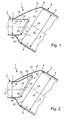
- Fig. 1 and 2 comprises an exhaust system 1 according to the invention and only partially shown at least one, here only in one end portion shown exhaust pipe 2 and a connected thereto catalyst or particulate filter unit 3, which is also shown only in a connected to the exhaust pipe 2 section.
- the exhaust system 1 is for attachment to an internal combustion engine, not shown here, which may be housed in particular in a motor vehicle, suitable and serves to dissipate the exhaust gases generated by the internal combustion engine.
- the catalyst or particle filter unit 3 comprises a housing 4, in which at least one monolith or at least one filter body 5 is accommodated.
- the monolith 5 or the filter body 5 is usually stored or positioned in the housing 4 with a bearing mat, not shown here.
- the filter body 5 may e.g. be a soot filter.
- the catalyst or particle filter unit 3 also has a funnel 6, which is connected with a first end 7 to the exhaust pipe 2 and with a second end 8 to the housing 4.
- the monolith or filter body 5 usually has a cross section 9, which is significantly larger than a cross section 10 of the exhaust pipe 2 in the region of the first funnel end 7. Accordingly, the funnel 6 widens from its first end 7 to its second end 8.
- the monolith or filter body cross section 9 is usually also larger than a cross section 11 of a mouth end 12 of the exhaust pipe 2.
- the monolith or filter body cross section 9 and the exhaust pipe cross section 10 are here transversely to the longitudinal center axis 13 of the monolith or filter body 5 or transversely to a Longitudinal center line 14 of the exhaust pipe 2 measured.
- the orifice cross section 11 is measured in a plane 21, in which the mouth end 12 extends.
- the exhaust pipe 2 is inserted concentrically with its mouth end 12 in the first funnel end 7, so that the longitudinal center line 14 of the exhaust pipe 2 coincides with a first longitudinal center axis 15 of the funnel 6, as long as the longitudinal center line 14 of the exhaust pipe 2 extends in a straight line. Furthermore, a second longitudinal central axis 16 of the funnel 6 coincides with the longitudinal central axis 13 of the monolith or of the filter body 5, since the monolith or filter body 5 is arranged concentrically with respect to the second funnel end 8.
- the funnel 6 is shaped so that its ends 7, 8 are inclined towards each other, i. the first longitudinal central axis 15 and the second longitudinal central axis 16 of the funnel 6 do not run parallel to one another but are inclined relative to one another.
- the exhaust pipe 2 does not axially connect with respect to the longitudinal central axis 13 of the monolith or of the filter body 5, but laterally against the funnel 6.
- the exhaust pipe 2 is inserted into the first funnel end 7, such that the mouth end 12 of the exhaust pipe 2 protrudes through the first funnel end 7 and projects into a funnel interior 17.
- the design of the exhaust pipe 2 and the geometry of the first funnel end 7 are coordinated so that the exhaust pipe 2 can be inserted from the monolith or filter body 5 away from the first funnel opening 7 into the funnel interior 17.
- a perpendicular to the longitudinal center line 14 of the exhaust pipe 2 measured cross section is constant and / or always equal to or smaller than an open inner cross section of the first funnel end 7.
- the exhaust pipe 2 may be formed so that its longitudinal center line 14 in the hopper interior 17 is rectilinear. Such an exhaust pipe 2 is particularly easy to produce. The insertion of the exhaust pipe 2 in the funnel 6 is characterized very simple.
- the exhaust pipe 2 is formed so that its longitudinal center line 14 within the hopper interior 17 has a curved course. Accordingly, this longitudinal center line 14 in the hopper interior 17 deviates from the first longitudinal central axis 15 in the first end 7 of the hopper 6.
- This course of the longitudinal center line 14 is achieved in that the exhaust pipe 2 is bent without changing its cross section in terms of shape and / or surface accordingly. It is important to ensure that the radii of curvature formed are chosen so that the exhaust pipe 2 in the desired manner in the first funnel end 7 can be inserted from the outside.
- this embodiment is somewhat more expensive to assemble, it opens up greater possibilities for designing the flow guidance in the interior of the catalyst or particle filter unit 3.
- the exhaust pipe 2 inserted laterally into the funnel 6 is used to influence the flow in the interior of the catalyst or particle filter unit 3.
- the mouth end 12 in the plane 21 whose normal or perpendicular to the longitudinal center line 14 is inclined at the point of intersection 19 with said mouth end plane 21.
- this inclination is - as here - chosen so that the muzzle end plane 21 extends substantially parallel to an end face 20 of the monolith and the filter body 5. That is, the normal or vertical of the mouth end plane 21 extends substantially parallel to the longitudinal center axis 13 of the monolith and the filter body 5.
- the flow guide from the mouth end 12 to the end face 20 of the monolith and the filter body 5 can be influenced and designed specifically.
- a flow guidance can be expedient in which a symmetrical, in particular uniform, distribution in the monolith or filter body cross-section 9 is formed with regard to gas temperature and / or flow rate.
- the in the Fig. 1 and 2 shown portion of the exhaust line 1 may be formed at the inlet of the catalyst or particulate filter unit 3, so that then the funnel 6 forms an inlet funnel 6.
- the catalyst or particle filter unit 3 may be designed according to the invention at its outlet, so that then the funnel 6 is designed as outlet funnel.
Description
- Die vorliegende Erfindung betrifft eine Abgasanlage für eine Brennkraftmaschine, insbesondere eines Kraftfahrzeugs, mit den Merkmalen des Anspruchs 1.
- Eine derartige Abgasanlage ist beispielsweise aus der
US 5,666,805 bekannt und umfasst ein Abgasrohr, das an eine Katalysatoreinheit angeschlossen ist, die in einem Gehäuse einen Monolithen enthält, dessen Querschnitt größer ist als ein Querschnitt des Abgasrohrs an einem Mündungsende des Abgasrohrs. Die Katalysatoreinheit weist außerdem einen Trichter auf, an den das Abgasrohr angeschlossen ist. Der Trichter ist als Winkelstück ausgestaltet, so dass Abgasrohr und Katalysatoreinheit mit zueinander geneigten Längsmittelachsen montierbar sind. Außerdem ist das Abgasrohr an seinem Mündungsende so geformt und dimensioniert, dass es in das zugehörige Trichterende einsteckbar ist. Bei der bekannten Abgasanlage ragt das Abgasrohr nicht in den Trichter hinein, sondern endet im zugehörigen Trichterende. - Aus der
DE 39 03 803 A1 ist eine Katalysatoreinheit bekannt, die in einem Gehäuse einen katalytisch wirksamen Monolithen enthält. Ein Querschnitt dieses Monolithen ist dabei größer als ein Querschnitt eines Abgasrohrs, an welches die Katalysatoreinheit angeschlossen werden soll. Zu diesem Zweck umfasst das Gehäuse einen Trichter, der einenends an das Abgasrohr anschließbar ist und anderenends in das Gehäuse übergeht, wobei sich der Trichter zwischen seinen Enden entsprechend aufweitet. Die Anschlußstelle, in welcher das Abgasrohr an dem Trichter angeschlossen ist, liegt dabei außerhalb eines Trichterinneren. Die bekannte Katalysatoreinheit besitzt außerdem ein im Trichter angeordnetes, längsverstellbar gelagertes Strömungsleitelement, das in Abhängigkeit seiner Relativlage den vom Abgas durchströmten Querschnitt des Monolithen definiert, um so das Erreichen der Anspringtemperatur des Katalysators zu beschleunigen. Der Einbau eines solchen Strömungsleitelements ist mit einem relativ hohen Aufwand verbunden. - Aus der
EP 0 724 070 A1 ist eine weitere Katalysatoreinheit bekannt, die ein Gehäuse aufweist, in dem ein Monolith angeordnet ist. Der Monolith ist dabei mit einem Sicherungs- oder Halteelement im Gehäuse fixiert. Das Gehäuse ist an seinen Enden mit Trichtern ausgestattet, die sich vom großen Querschnitt im Bereich des Monolithen zu einem kleinen Querschnitt bis zu einem Flansch hin verjüngen. Die Trichter umfassen dabei auf jeder Seite des Gehäuses einen Außentrichter sowie einen konzentrisch darin angeordneten Innentrichter, der so dimensioniert ist, dass er möglichst dicht am Monolithen den Querschnitt des Monolithen abdeckt. Hierdurch wird erreicht, dass das Sicherungs- oder Halteelement im Betrieb keiner Gasströmung ausgesetzt ist. Über die Flansche ist das Gehäuse an Abgasrohre anschließbar. Der Einbau derartiger zusätzlicher Innentrichter ist mit einem vergleichsweise hohen Aufwand verbunden. - Für den Fall, dass eine mit einer Katalysator- oder Partikelfiltereinheit ausgestattete Abgasanlage in einem Kraftfahrzeug verwendet werden soll, handelt es sich bei der Abgasanlage um ein im Rahmen einer Großserienfertigung hergestelltes Produkt. Es besteht daher stets der Wunsch, eine derartige Abgasanlage einfacher aufzubauen, um sie preiswerter herstellen zu können.
- Dementsprechend beschäftigt sich die vorliegende Erfindung mit dem Problem, für eine Abgasanlage der eingangs genannten Art eine verbesserte Ausführungsform anzugeben, die insbesondere einen einfachen Aufbau besitzt und preiswert herstellbar ist.
- Dieses Problem wird erfindungsgemäß durch den Gegenstand des unabhängigen Anspruchs 1 gelöst. Vorteilhafte Ausführungsformen sind Gegenstand der abhängigen Ansprüche 2 bis 4.
- Die vorliegende Erfindung beruht auf dem allgemeinen Gedanken, das Gehäuse der Katalysator- oder Partikelfiltereinheit und das daran anzuschließende Abgasrohr so aufeinander abzustimmen, dass das Abgasrohr in den Trichter des Gehäuses seitlich, also gegenüber einer Längsmittelachse des Monolithen bzw. des Filterkörpers geneigt von außen einsteckbar ist. Auf diese Weise wird die Anbindung des Abgasrohrs an das Gehäuse der Katalysator- oder Partikelfiltereinheit vereinfacht. Durch das seitliche Einstecken des Abgasrohrs in den Trichter ergibt sich außerdem die Möglichkeit, durch eine entsprechende Gestaltung des Mündungsendes innerhalb des Trichters gezielt eine gewünschte Strömungsführung zu erzeugen. Insbesondere lässt sich dadurch die Verteilung der zugeführten Abgase auf den Monolith- bzw. Filterkörperquerschnitt optimieren. Des Weiteren bildet sich durch das in das Trichterinnere hineinragende Mündungsende zwischen dem Trichter und dem Abgasrohr ein ringförmiger Spalt aus, der im Betrieb quasi nicht durchströmt ist und somit eine thermische Isolation für den Trichter bewirkt.
- Außerdem ist bei der erfindungsgemäßen Abgasanlage das Mündungsende so angeordnet, dass es in einer Ebene liegt, deren Normale gegenüber der Längsmittellinie des Abgasrohrs im Mündungsende geneigt ist. Hierdurch lässt sich die Strömung im Inneren der Katalysator- oder Partikelfiltereinheit besonders deutlich beeinflussen.
- Erfindungsgemäß liegt das Mündungsende in einer Ebene, deren Normale im wesentlichen parallel zur Längsmittelachse des Monolithen bzw. des Filterkörpers verläuft. Bei dieser Bauweise ist das Abgasrohr an seinem Mündungsende quasi abgeschrägt, wodurch sich der Austrittsquerschnitt am Mündungsende vergrößert, ohne dass dazu das Abgasrohr aufgeweitet werden muss. Das bedeutet, dass mit Hilfe des so gestalteten Mündungsendes im Trichterinneren die Abgasströmung aufgeweitet werden kann, obwohl das Abgasrohr mit seinem Mündungsende von außen, also von der vom Monolithen bzw. vom Filterkörper abgewandten Seite in den Trichter einsteckbar ist. Eine strömungsleitende Formgebung am Mündungsende kann somit bei der erfindungsgemäßen Abgasanlage ohne großen Aufwand realisiert werden.
- Weitere wichtige Merkmale und Vorteile der Erfindung ergeben sich aus den Unteransprüchen, aus den Zeichnungen und aus der zugehörigen Figurenbeschreibung anhand der Zeichnungen.
- Es versteht sich, dass die vorstehend genannten und die nachstehend noch zu erläuternden Merkmale nicht nur in der jeweils angegebenen Kombination, sondern auch in anderen Kombinationen oder in Alleinstellung verwendbar sind, ohne den Rahmen der vorliegenden Erfindung zu verlassen.
- Bevorzugte Ausführungsbeispiele der Erfindung sind in den Zeichnungen dargestellt und werden in der nachfolgenden Beschreibung näher erläutert, wobei sich gleiche Bezugszeichen auf gleiche oder funktional gleiche oder ähnliche Bauteile beziehen.
- Es zeigen, jeweils schematisch,
- Fig. 1
- einen Längsschnitt durch eine erfindungsgemäße Abgasanlage in einem Bereich, in dem ein Abgasrohr an eine Katalysator- oder Partikelfiltereinheit angeschlossen ist,
- Fig. 2
- eine Darstellung wie in
Fig. 1 , jedoch bei einer anderen Ausführungsform. - Entsprechend den
Fig. 1 und 2 umfasst eine erfindungsgemäße und nur teilweise dargestellte Abgasanlage 1 zumindest ein, hier nur in einem Endabschnitt dargestelltes Abgasrohr 2 sowie eine daran angeschlossene Katalysator- oder Partikelfiltereinheit 3, die ebenfalls nur in einem mit dem Abgasrohr 2 verbundenen Abschnitt dargestellt ist. Die Abgasanlage 1 ist zum Anbau an eine hier nicht gezeigte Brennkraftmaschine, die insbesondere in einem Kraftfahrzeug untergebracht sein kann, geeignet und dient zur Abführung der von der Brennkraftmaschine erzeugten Abgase. - Die Katalysator- oder Partikelfiltereinheit 3 umfasst ein Gehäuse 4, in dem wenigstens ein Monolith oder wenigstens ein Filterkörper 5 untergebracht ist. Der Monolith 5 bzw. der Filterkörper 5 wird dabei üblicherweise mit einer hier nicht gezeigten Lagermatte im Gehäuse 4 gelagert bzw. positioniert. Der Filterkörper 5 kann z.B. ein Rußfilter sein. Die Katalysator- oder Partikelfiltereinheit 3 weist außerdem einen Trichter 6 auf, der mit einem ersten Ende 7 an das Abgasrohr 2 und mit einem zweiten Ende 8 an das Gehäuse 4 angeschlossen ist. Der Monolith bzw. Filterkörper 5 besitzt üblicherweise einen Querschnitt 9, der deutlich größer als ein Querschnitt 10 des Abgasrohrs 2 im Bereich des ersten Trichterendes 7. Dementsprechend weitet sich der Trichter 6 von seinem ersten Ende 7 bis zu seinem zweiten Ende 8 auf. Üblicherweise ist der Monolith- bzw. Filterkörperquerschnitt 9 auch größer als ein Querschnitt 11 eines Mündungsendes 12 des Abgasrohrs 2. Der Monolith- bzw. Filterkörperquerschnitt 9 und der Abgasrohrquerschnitt 10 sind hier quer zur Längsmittelachse 13 des Monolithen bzw. Filterkörpers 5 bzw. quer zu einer Längsmittellinie 14 des Abgasrohrs 2 gemessen. Im Unterschied dazu ist der Mündungsquerschnitt 11 in einer Ebene 21 gemessen, in welcher sich das Mündungsende 12 erstreckt.
- Das Abgasrohr 2 ist mit seinem Mündungsende 12 in das erste Trichterende 7 konzentrisch eingesteckt, so dass die Längsmittellinie 14 des Abgasrohrs 2 mit einer ersten Längsmittelachse 15 des Trichters 6 zusammenfällt, solange sich die Längsmittellinie 14 des Abgasrohrs 2 geradlinig erstreckt. Des Weiteren fällt eine zweite Längsmittelachse 16 des Trichters 6 mit der Längsmittelachse 13 des Monolithen bzw. des Filterkörpers 5 zusammen, da der Monolith bzw. Filterkörper 5 konzentrisch bezüglich des zweiten Trichterendes 8 angeordnet ist.
- Erfindungsgemäß ist der Trichter 6 so geformt, dass seine Enden 7,8 gegeneinander geneigt sind, d.h. die erste Längsmittelachse 15 und die zweite Längsmittelachse 16 des Trichters 6 verlaufen nicht parallel zueinander, sondern sind zueinander geneigt. Durch diese Bauweise schließt das Abgasrohr 2 bezüglich der Längsmittelachse 13 des Monolithen bzw. des Filterkörpers 5 nicht axial, sondern seitlich an den Trichter 6 an. Zu diesem Zweck ist das Abgasrohr 2 in das erste Trichterende 7 eingesteckt, derart, dass das Mündungsende 12 des Abgasrohrs 2 durch das erste Trichterende 7 hindurchragt und in ein Trichterinneres 17 hineinragt. Dabei sind die Formgebung des in den Trichter 6 eingesteckten Abschnitts des Abgasrohrs 2 und die Orientierung des ersten Trichterendes 7 so aufeinander abgestimmt, dass der in das Trichterinnere 17 hineinragende Abschnitt des Abgasrohrs 2 den Trichter 6 - abgesehen im ersten Trichterende 7 - nicht berührt. Das bedeutet, dass das Mündungsende 12 im Trichterinneren 17 freistehend angeordnet oder positioniert ist. Durch diese Bauweise kann sich im Trichterinneren 17 zwischen dem Abgasrohr 2 und dem Trichter 6 ein ringförmig geschlossener Spaltraum 18 ausbilden, der im Betrieb des Abgasstrangs 1 im wesentlichen nicht durchströmt ist, sondern ein Totwassergebiet bildet. Für den Trichter 6 ergibt sich in dem an den Spaltraum 18 angrenzenden Abschnitt dadurch eine thermische Isolierung gegenüber der heißen Abgasströmung.
- Erfindungswesentlich ist außerdem, dass die Ausgestaltung des Abgasrohrs 2 und die Geometrie des ersten Trichterendes 7 so aufeinander abgestimmt sind, dass das Abgasrohr 2 von der, vom Monolithen bzw. vom Filterkörper 5 abgewandten Seite durch die erste Trichteröffnung 7 in das Trichterinnere 17 einsteckbar ist. Insbesondere ist dazu ein senkrecht zur Längsmittellinie 14 des Abgasrohrs 2 gemessener Querschnitt konstant und/oder stets gleich groß wie oder kleiner als ein offener Innenquerschnitt des ersten Trichterendes 7. Durch diese Bauweise wird gewährleistet, dass das Abgasrohr 2 auch dann in den Trichter 6 einführbar ist, wenn dieser bereits fest mit dem Gehäuse 4 verbunden ist. Die Montage der Abgasanlage 1 wird dadurch vereinfacht.
- Entsprechend
Fig. 1 kann das Abgasrohr 2 so geformt sein, dass seine Längsmittellinie 14 im Trichterinneren 17 geradlinig verläuft. Ein derartiges Abgasrohr 2 ist besonders einfach herstellbar. Das Einführen des Abgasrohrs 2 in den Trichter 6 gestaltet sich dadurch sehr einfach. - Im Unterschied dazu ist bei der Ausführungsform gemäß
Fig. 2 das Abgasrohr 2 so geformt, dass seine Längsmittellinie 14 innerhalb des Trichterinnerens 17 einen gekrümmten Verlauf besitzt. Dementsprechend weicht diese Längsmittellinie 14 im Trichterinneren 17 von der ersten Längsmittelachse 15 im ersten Ende 7 des Trichters 6 ab. Erreicht wird dieser Verlauf der Längsmittellinie 14 dadurch, dass das Abgasrohr 2 ohne Veränderung seines Querschnitts hinsichtlich Form und/oder Fläche entsprechend gebogen wird. Dabei ist darauf zu achten, dass die ausgebildeten Krümmungsradien so gewählt sind, dass das Abgasrohr 2 in der gewünschten Weise in das erste Trichterende 7 von außen einsteckbar ist. Diese Ausführungsform ist zwar etwas aufwändiger zu montieren, eröffnet jedoch größere Möglichkeiten für die Gestaltung der Strömungsführung im Inneren der Katalysator- oder Partikelfiltereinheit 3. - Durch den hier beschriebenen Aufbau wird das seitlich in den Trichter 6 eingesteckte Abgasrohr 2 zur Beeinflussung der Strömung im Inneren der Katalysator- oder Partikelfiltereinheit 3 genutzt. Wie hier gezeigt, ist es insbesondere möglich, das Mündungsende 12 in die Ebene 21 zu legen, deren Normale oder Senkrechte gegenüber der Längsmittellinie 14 im Schnittpunkt 19 mit der genannten Mündungsend-Ebene 21 geneigt ist. Insbesondere ist diese Neigung - wie hier - so gewählt, dass die Mündungsend-Ebene 21 im wesentlichen parallel zu einer Stirnseite 20 des Monolithen bzw. des Filterkörpers 5 verläuft. D.h., die Normale bzw. Senkrechte der Mündungsend-Ebene 21 erstreckt sich im wesentlichen parallel zur Längsmittelachse 13 des Monolithen bzw. des Filterkörpers 5. In Verbindung mit dem seitlichen Einstecken des Abgasrohrs 2 in den Trichter 6 ergibt sich dadurch eine Aufweitung des durchströmbaren Querschnitts im Mündungsende 12. Durch die Formgebung und Dimensionierung des Abgasrohrs 2 am Mündungsende 12 kann die Strömungsführung vom Mündungsende 12 zur Stirnseite 20 des Monolithen bzw. des Filterkörpers 5 beeinflusst und gezielt gestaltet werden. Insbesondere ist es dadurch möglich, die heiße Abgasströmung in einer gewünschten Weise auf den Querschnitt des Monolithen bzw. des Filterkörpers 5 zu verteilen. Zweckmäßig kann dabei eine Strömungsführung sein, bei der sich im Hinblick auf Gastemperatur und/oder Strömungsgeschwindigkeit eine symmetrische, insbesondere gleichmäßige, Verteilung im Monolith- bzw. Filterkörperquerschnitt 9 ausbildet.
- Bemerkenswert ist hierbei, dass unterschiedliche Strömungsführungsmaßnahmen durch die unterschiedliche Gestaltung des Abgasrohrs 2 realisierbar sind, ohne dass dabei die Gestaltung des Trichters 6 und somit der Katalysator- oder Partikelfiltereinheit 3 verändert werden muss. Insbesondere ist es bei der Erfindung somit möglich, unterschiedliche Strömungsführungsvarianten bei gleichen Katalysator- oder Partikelfiltereinheiten zu realisieren, indem lediglich die Gestaltung des in den Trichter 6 eingesteckten Endabschnitts des Abgasrohrs 2 entsprechend gestaltet wird. Die Variantenbildung kann dadurch besonders preiswert realisiert werden.
- Anstelle des hier in
Fig. 2 gezeigten gekrümmten oder gebogenen Verlaufs der Längsmittellinie 14 kann diese im Trichterinneren 17 auch einen abgewinkelten Verlauf besitzen. - Der in den
Fig. 1 und 2 gezeigte Bereich des Abgasstrangs 1 kann am Einlass der Katalysator- oder Partikelfiltereinheit 3 ausgebildet sein, so dass dann der Trichter 6 einen Einlaßtrichter 6 bildet. Alternativ oder zusätzlich kann die Katalysator- oder Partikelfiltereinheit 3 an ihrem Auslaß erfindungsgemäß gestaltet sein, so dass dann der Trichter 6 als Auslaßtrichter ausgestaltet ist.
Claims (3)
- Abgasanlage für eine Brennkraftmaschine, insbesondere eines Kraftfahrzeugs,- mit einem Abgasrohr (2), das an eine Katalysator- oder Partikelfiltereinheit (3) angeschlossen ist, die in einem Gehäuse (4) wenigstens einen Monolithen (5) oder wenigstens einen Filterkörper (5) enthält, dessen Querschnitt (9) größer ist als ein Querschnitt (11) des Abgasrohrs (2) an einem Mündungsende (12) des Abgasrohrs (2),- wobei die Katalysator- oder Partikelfiltereinheit (3) einen Trichter (6) aufweist, an den das Abgasrohr (2) angeschlossen ist,- wobei der Trichter (6) an seinem an das Abgasrohr (2) angeschlossenen ersten Ende (7) eine erste Längsmittelachse (15) und an seinem, dem Monolithen (5) oder dem Filterkörper (5) zugewandten zweiten Ende (8) eine zweite Längsmittelachse (16) aufweist, die gegenüber der ersten Längsmittelachse (15) geneigt ist,- wobei das Abgasrohr (2) an seinem Mündungsende (12) so geformt und dimensioniert ist, dass es in das erste Trichterende (7) einsteckbar ist,dadurch gekennzeichnet,- dass das Abgasrohr (2) mit seinem Mündungsende (12) durch das erste Trichterende (7) hindurch in ein Trichterinneres (17) freistehend hineinragt,- dass das Mündungsende (12) in einer Ebene (21) liegt, deren Normale gegenüber der Längsmittellinie (14) des Abgasrohrs (2) im Mündungsende (12) geneigt ist,- dass das Mündungsende (12) in einer Ebene (21) liegt, deren Normale im wesentlichen parallel zur Längsmittelachse (13) des Monolithen (5) oder des Filterkörpers (5) verläuft.
- Abgasanlage nach Anspruch 1,
dadurch gekennzeichnet,
dass das Abgasrohr (2) im Trichterinneren (17) eine geradlinig verlaufende Längsmittellinie (14) aufweist. - Abgasanlage nach Anspruch 1,
dadurch gekennzeichnet,
dass das Abgasrohr (2) im Trichterinneren (17) eine gebogen oder gekrümmt oder abgewinkelt verlaufende Längsmittellinie (14) aufweist.
Applications Claiming Priority (2)
| Application Number | Priority Date | Filing Date | Title |
|---|---|---|---|
| DE10300384 | 2003-01-09 | ||
| DE2003100384 DE10300384B4 (de) | 2003-01-09 | 2003-01-09 | Abgasanlage |
Publications (3)
| Publication Number | Publication Date |
|---|---|
| EP1437489A1 EP1437489A1 (de) | 2004-07-14 |
| EP1437489B1 EP1437489B1 (de) | 2006-11-29 |
| EP1437489B2 true EP1437489B2 (de) | 2012-03-07 |
Family
ID=32478169
Family Applications (1)
| Application Number | Title | Priority Date | Filing Date |
|---|---|---|---|
| EP03024193A Expired - Fee Related EP1437489B2 (de) | 2003-01-09 | 2003-10-21 | Abgasanlage |
Country Status (2)
| Country | Link |
|---|---|
| EP (1) | EP1437489B2 (de) |
| DE (2) | DE10300384B4 (de) |
Families Citing this family (5)
| Publication number | Priority date | Publication date | Assignee | Title |
|---|---|---|---|---|
| KR101000224B1 (ko) | 2008-12-04 | 2010-12-10 | 현대자동차주식회사 | 차량용 촉매장치 |
| DE102010006829B4 (de) * | 2010-02-03 | 2013-08-14 | Benteler Automobiltechnik Gmbh | Abgasanlage |
| DE102011079906A1 (de) * | 2011-07-27 | 2013-01-31 | Bayerische Motoren Werke Aktiengesellschaft | Abgasanlage für ein Kraftfahrzeug |
| US10167765B2 (en) * | 2016-07-12 | 2019-01-01 | GM Global Technology Operations LLC | Exhaust gas seal |
| CN109404098A (zh) * | 2018-12-14 | 2019-03-01 | 东风汽车集团有限公司 | 一种横置后排增压发动机twc及gpf紧耦合热端催化器及排气系统 |
Citations (2)
| Publication number | Priority date | Publication date | Assignee | Title |
|---|---|---|---|---|
| DE4408130A1 (de) † | 1994-03-10 | 1995-09-14 | Bayerische Motoren Werke Ag | Vorrichtung zur Abgasreinigung bei Brennkraftmaschinen |
| DE19824428A1 (de) † | 1998-05-30 | 1999-12-02 | Daimler Chrysler Ag | Abgaskatalysatorkörper mit unterschiedlichen, parallelen Zellstrukturbereichen |
Family Cites Families (8)
| Publication number | Priority date | Publication date | Assignee | Title |
|---|---|---|---|---|
| SE450274B (sv) * | 1985-12-13 | 1987-06-15 | Saab Scania Ab | Katalysatorhus ingaende i ett fordons avgassystem |
| DE3903803A1 (de) * | 1989-02-09 | 1990-08-16 | Bayerische Motoren Werke Ag | Gehaeuse eines abgaskatalysators |
| DE4223648C2 (de) * | 1992-07-17 | 1996-02-01 | Zeuna Staerker Kg | Katalytische Abgasreinigungsvorrichtung |
| DE4440160C2 (de) * | 1993-12-03 | 1997-02-27 | Gen Motors Corp | Katalysator-Diffusor |
| DE9421332U1 (de) * | 1994-06-16 | 1995-10-05 | Boysen Friedrich Gmbh Co Kg | Vorrichtung zur katalytischen Reinigung bzw. Zerlegung von heißen Abgasen |
| JP3294036B2 (ja) * | 1995-01-26 | 2002-06-17 | 日本碍子株式会社 | ハニカム触媒コンバータ |
| WO2000039437A1 (en) * | 1998-12-28 | 2000-07-06 | Corning Incorporated | A converter for use in the treatment of gases |
| DE10002218A1 (de) * | 2000-01-20 | 2001-07-26 | Eberspaecher J Gmbh & Co | Abgaskatalysator |
-
2003
- 2003-01-09 DE DE2003100384 patent/DE10300384B4/de not_active Expired - Fee Related
- 2003-10-21 DE DE50305832T patent/DE50305832D1/de not_active Expired - Lifetime
- 2003-10-21 EP EP03024193A patent/EP1437489B2/de not_active Expired - Fee Related
Patent Citations (2)
| Publication number | Priority date | Publication date | Assignee | Title |
|---|---|---|---|---|
| DE4408130A1 (de) † | 1994-03-10 | 1995-09-14 | Bayerische Motoren Werke Ag | Vorrichtung zur Abgasreinigung bei Brennkraftmaschinen |
| DE19824428A1 (de) † | 1998-05-30 | 1999-12-02 | Daimler Chrysler Ag | Abgaskatalysatorkörper mit unterschiedlichen, parallelen Zellstrukturbereichen |
Also Published As
| Publication number | Publication date |
|---|---|
| EP1437489A1 (de) | 2004-07-14 |
| DE50305832D1 (de) | 2007-01-11 |
| EP1437489B1 (de) | 2006-11-29 |
| DE10300384A1 (de) | 2004-07-29 |
| DE10300384B4 (de) | 2005-12-01 |
Similar Documents
| Publication | Publication Date | Title |
|---|---|---|
| EP3216992B1 (de) | Mischer | |
| EP2161423B1 (de) | Abgasanlage für Dieselfahrzeuge mit einem SCR-Katalysator | |
| EP2233709B1 (de) | Abgasbehandlungseinrichtung | |
| EP3478947B1 (de) | Mischervorrichtung für ein abgasnachbehandlungssystem eines kraftfahrzeugs, abgasnachbehandlungssystem und kraftfahrzeug | |
| DE102004020138B4 (de) | Reduktionsmittelzugabesystem | |
| DE102008031136B4 (de) | Abgasbehandlungseinrichtung | |
| EP2027372B1 (de) | Nebenstromfilter mit verbessertem filterwirkungsgrad | |
| WO2008107151A1 (de) | Abgasnachbehandlungseinrichtung eines kraftfahrzeugs | |
| EP4086439B1 (de) | Abgasbehandlungsmodul | |
| EP3412879B1 (de) | Abgasnachbehandlungsvorrichtung einer brennkraftmaschine eines kraftfahrzeugs | |
| EP1437489B2 (de) | Abgasanlage | |
| DE102018107766A1 (de) | Abgasanlage und Mischerbaugruppe für eine Abgasanlage | |
| EP3597997B1 (de) | Fahrzeugheizgerät | |
| DE102004018693B4 (de) | Abgasanlage | |
| EP3109423B1 (de) | Abgasschalldämpfer | |
| DE4212505C1 (en) | Double wall pipe providing intermediate chamber for lambda sensor support - is insulated to prevent loss of heat from exhaust gas of motor vehicle so that catalyser can be effective from cold start | |
| DE102006038204B4 (de) | Eingangstrichter für eine Abgasbehandlungseinrichtung | |
| EP3327261B1 (de) | Abgasbehandlungsanordnung | |
| EP0561019B1 (de) | Vorrichtung zur Lagefixierung einer Innenschale in einem Gehäuse einer Abgasanlage für Fahrzeuge | |
| EP3851646B1 (de) | Gas/gas-mischer zum einleiten von gas in den abgasstrom einer brennkraftmaschine | |
| EP0451662B1 (de) | Rekuperatorbrenner | |
| EP3514342B1 (de) | Schalldämpfer | |
| DE1294393B (de) | Auspufftopf fuer Kraftfahrzeuge | |
| WO2008025600A1 (de) | Filtereinrichtung, insbesondere für ein abgassystem einer brennkraftmaschine | |
| DE102005051920B4 (de) | Rohrleitungsstück für eine Abgasleitung |
Legal Events
| Date | Code | Title | Description |
|---|---|---|---|
| PUAI | Public reference made under article 153(3) epc to a published international application that has entered the european phase |
Free format text: ORIGINAL CODE: 0009012 |
|
| AK | Designated contracting states |
Kind code of ref document: A1 Designated state(s): AT BE BG CH CY CZ DE DK EE ES FI FR GB GR HU IE IT LI LU MC NL PT RO SE SI SK TR |
|
| AX | Request for extension of the european patent |
Extension state: AL LT LV MK |
|
| 17P | Request for examination filed |
Effective date: 20040727 |
|
| AKX | Designation fees paid |
Designated state(s): DE FR IT |
|
| GRAP | Despatch of communication of intention to grant a patent |
Free format text: ORIGINAL CODE: EPIDOSNIGR1 |
|
| GRAS | Grant fee paid |
Free format text: ORIGINAL CODE: EPIDOSNIGR3 |
|
| GRAA | (expected) grant |
Free format text: ORIGINAL CODE: 0009210 |
|
| AK | Designated contracting states |
Kind code of ref document: B1 Designated state(s): DE FR IT |
|
| REF | Corresponds to: |
Ref document number: 50305832 Country of ref document: DE Date of ref document: 20070111 Kind code of ref document: P |
|
| ET | Fr: translation filed | ||
| PLBI | Opposition filed |
Free format text: ORIGINAL CODE: 0009260 |
|
| PLAX | Notice of opposition and request to file observation + time limit sent |
Free format text: ORIGINAL CODE: EPIDOSNOBS2 |
|
| 26 | Opposition filed |
Opponent name: FRIEDRICH BOYSEN GMBH & CO. KG Effective date: 20070829 |
|
| PLBB | Reply of patent proprietor to notice(s) of opposition received |
Free format text: ORIGINAL CODE: EPIDOSNOBS3 |
|
| APBM | Appeal reference recorded |
Free format text: ORIGINAL CODE: EPIDOSNREFNO |
|
| APBP | Date of receipt of notice of appeal recorded |
Free format text: ORIGINAL CODE: EPIDOSNNOA2O |
|
| APAH | Appeal reference modified |
Free format text: ORIGINAL CODE: EPIDOSCREFNO |
|
| APBQ | Date of receipt of statement of grounds of appeal recorded |
Free format text: ORIGINAL CODE: EPIDOSNNOA3O |
|
| APBU | Appeal procedure closed |
Free format text: ORIGINAL CODE: EPIDOSNNOA9O |
|
| RIC2 | Information provided on ipc code assigned after grant |
Ipc: F01N 3/28 20060101AFI20111004BHEP Ipc: F01N 13/18 20100101ALI20111004BHEP |
|
| PUAH | Patent maintained in amended form |
Free format text: ORIGINAL CODE: 0009272 |
|
| STAA | Information on the status of an ep patent application or granted ep patent |
Free format text: STATUS: PATENT MAINTAINED AS AMENDED |
|
| 27A | Patent maintained in amended form |
Effective date: 20120307 |
|
| AK | Designated contracting states |
Kind code of ref document: B2 Designated state(s): DE FR IT |
|
| REG | Reference to a national code |
Ref country code: DE Ref legal event code: R102 Ref document number: 50305832 Country of ref document: DE Effective date: 20120307 |
|
| REG | Reference to a national code |
Ref country code: DE Ref legal event code: R082 Ref document number: 50305832 Country of ref document: DE Representative=s name: BRP RENAUD & PARTNER, DE |
|
| REG | Reference to a national code |
Ref country code: DE Ref legal event code: R082 Ref document number: 50305832 Country of ref document: DE Representative=s name: BRP RENAUD & PARTNER, DE Effective date: 20131022 Ref country code: DE Ref legal event code: R081 Ref document number: 50305832 Country of ref document: DE Owner name: EBERSPAECHER EXHAUST TECHNOLOGY GMBH & CO. KG, DE Free format text: FORMER OWNER: J. EBERSPAECHER GMBH & CO. KG, 73730 ESSLINGEN, DE Effective date: 20131022 Ref country code: DE Ref legal event code: R082 Ref document number: 50305832 Country of ref document: DE Representative=s name: BRP RENAUD UND PARTNER MBB RECHTSANWAELTE PATE, DE Effective date: 20131022 Ref country code: DE Ref legal event code: R082 Ref document number: 50305832 Country of ref document: DE Representative=s name: BRP RENAUD UND PARTNER MBB, DE Effective date: 20131022 |
|
| REG | Reference to a national code |
Ref country code: FR Ref legal event code: CD Owner name: EBERSPACHER CLIMATE CONTROL SYSTEMS GMBH & CO. KG Effective date: 20131129 |
|
| REG | Reference to a national code |
Ref country code: FR Ref legal event code: TP Owner name: EBERSPACHER EXHAUST TECHNOLOGY GMBH & CO. KG, DE Effective date: 20140204 |
|
| REG | Reference to a national code |
Ref country code: FR Ref legal event code: PLFP Year of fee payment: 13 |
|
| REG | Reference to a national code |
Ref country code: FR Ref legal event code: PLFP Year of fee payment: 14 |
|
| REG | Reference to a national code |
Ref country code: FR Ref legal event code: PLFP Year of fee payment: 15 |
|
| REG | Reference to a national code |
Ref country code: FR Ref legal event code: PLFP Year of fee payment: 16 |
|
| PGFP | Annual fee paid to national office [announced via postgrant information from national office to epo] |
Ref country code: IT Payment date: 20201030 Year of fee payment: 18 |
|
| REG | Reference to a national code |
Ref country code: DE Ref legal event code: R081 Ref document number: 50305832 Country of ref document: DE Owner name: PUREM GMBH, DE Free format text: FORMER OWNER: EBERSPAECHER EXHAUST TECHNOLOGY GMBH & CO. KG, 66539 NEUNKIRCHEN, DE |
|
| PGFP | Annual fee paid to national office [announced via postgrant information from national office to epo] |
Ref country code: DE Payment date: 20211020 Year of fee payment: 19 |
|
| PGFP | Annual fee paid to national office [announced via postgrant information from national office to epo] |
Ref country code: FR Payment date: 20211021 Year of fee payment: 19 |
|
| REG | Reference to a national code |
Ref country code: DE Ref legal event code: R119 Ref document number: 50305832 Country of ref document: DE |
|
| PG25 | Lapsed in a contracting state [announced via postgrant information from national office to epo] |
Ref country code: IT Free format text: LAPSE BECAUSE OF NON-PAYMENT OF DUE FEES Effective date: 20211031 |
|
| PG25 | Lapsed in a contracting state [announced via postgrant information from national office to epo] |
Ref country code: FR Free format text: LAPSE BECAUSE OF NON-PAYMENT OF DUE FEES Effective date: 20221031 Ref country code: DE Free format text: LAPSE BECAUSE OF NON-PAYMENT OF DUE FEES Effective date: 20230503 |