EP1437489B2 - Système pour gaz d'échappement - Google Patents
Système pour gaz d'échappement Download PDFInfo
- Publication number
- EP1437489B2 EP1437489B2 EP03024193A EP03024193A EP1437489B2 EP 1437489 B2 EP1437489 B2 EP 1437489B2 EP 03024193 A EP03024193 A EP 03024193A EP 03024193 A EP03024193 A EP 03024193A EP 1437489 B2 EP1437489 B2 EP 1437489B2
- Authority
- EP
- European Patent Office
- Prior art keywords
- exhaust pipe
- funnel
- monolith
- exhaust
- section
- Prior art date
- Legal status (The legal status is an assumption and is not a legal conclusion. Google has not performed a legal analysis and makes no representation as to the accuracy of the status listed.)
- Expired - Fee Related
Links
Images
Classifications
-
- F—MECHANICAL ENGINEERING; LIGHTING; HEATING; WEAPONS; BLASTING
- F01—MACHINES OR ENGINES IN GENERAL; ENGINE PLANTS IN GENERAL; STEAM ENGINES
- F01N—GAS-FLOW SILENCERS OR EXHAUST APPARATUS FOR MACHINES OR ENGINES IN GENERAL; GAS-FLOW SILENCERS OR EXHAUST APPARATUS FOR INTERNAL COMBUSTION ENGINES
- F01N13/00—Exhaust or silencing apparatus characterised by constructional features ; Exhaust or silencing apparatus, or parts thereof, having pertinent characteristics not provided for in, or of interest apart from, groups F01N1/00 - F01N5/00, F01N9/00, F01N11/00
- F01N13/18—Construction facilitating manufacture, assembly, or disassembly
- F01N13/1838—Construction facilitating manufacture, assembly, or disassembly characterised by the type of connection between parts of exhaust or silencing apparatus, e.g. between housing and tubes, between tubes and baffles
-
- F—MECHANICAL ENGINEERING; LIGHTING; HEATING; WEAPONS; BLASTING
- F01—MACHINES OR ENGINES IN GENERAL; ENGINE PLANTS IN GENERAL; STEAM ENGINES
- F01N—GAS-FLOW SILENCERS OR EXHAUST APPARATUS FOR MACHINES OR ENGINES IN GENERAL; GAS-FLOW SILENCERS OR EXHAUST APPARATUS FOR INTERNAL COMBUSTION ENGINES
- F01N13/00—Exhaust or silencing apparatus characterised by constructional features ; Exhaust or silencing apparatus, or parts thereof, having pertinent characteristics not provided for in, or of interest apart from, groups F01N1/00 - F01N5/00, F01N9/00, F01N11/00
- F01N13/08—Other arrangements or adaptations of exhaust conduits
-
- F—MECHANICAL ENGINEERING; LIGHTING; HEATING; WEAPONS; BLASTING
- F01—MACHINES OR ENGINES IN GENERAL; ENGINE PLANTS IN GENERAL; STEAM ENGINES
- F01N—GAS-FLOW SILENCERS OR EXHAUST APPARATUS FOR MACHINES OR ENGINES IN GENERAL; GAS-FLOW SILENCERS OR EXHAUST APPARATUS FOR INTERNAL COMBUSTION ENGINES
- F01N13/00—Exhaust or silencing apparatus characterised by constructional features ; Exhaust or silencing apparatus, or parts thereof, having pertinent characteristics not provided for in, or of interest apart from, groups F01N1/00 - F01N5/00, F01N9/00, F01N11/00
- F01N13/18—Construction facilitating manufacture, assembly, or disassembly
- F01N13/1805—Fixing exhaust manifolds, exhaust pipes or pipe sections to each other, to engine or to vehicle body
-
- F—MECHANICAL ENGINEERING; LIGHTING; HEATING; WEAPONS; BLASTING
- F01—MACHINES OR ENGINES IN GENERAL; ENGINE PLANTS IN GENERAL; STEAM ENGINES
- F01N—GAS-FLOW SILENCERS OR EXHAUST APPARATUS FOR MACHINES OR ENGINES IN GENERAL; GAS-FLOW SILENCERS OR EXHAUST APPARATUS FOR INTERNAL COMBUSTION ENGINES
- F01N3/00—Exhaust or silencing apparatus having means for purifying, rendering innocuous, or otherwise treating exhaust
- F01N3/08—Exhaust or silencing apparatus having means for purifying, rendering innocuous, or otherwise treating exhaust for rendering innocuous
- F01N3/10—Exhaust or silencing apparatus having means for purifying, rendering innocuous, or otherwise treating exhaust for rendering innocuous by thermal or catalytic conversion of noxious components of exhaust
- F01N3/24—Exhaust or silencing apparatus having means for purifying, rendering innocuous, or otherwise treating exhaust for rendering innocuous by thermal or catalytic conversion of noxious components of exhaust characterised by constructional aspects of converting apparatus
- F01N3/28—Construction of catalytic reactors
- F01N3/2892—Exhaust flow directors or the like, e.g. upstream of catalytic device
-
- F—MECHANICAL ENGINEERING; LIGHTING; HEATING; WEAPONS; BLASTING
- F01—MACHINES OR ENGINES IN GENERAL; ENGINE PLANTS IN GENERAL; STEAM ENGINES
- F01N—GAS-FLOW SILENCERS OR EXHAUST APPARATUS FOR MACHINES OR ENGINES IN GENERAL; GAS-FLOW SILENCERS OR EXHAUST APPARATUS FOR INTERNAL COMBUSTION ENGINES
- F01N2470/00—Structure or shape of gas passages, pipes or tubes
- F01N2470/20—Dimensional characteristics of tubes, e.g. length, diameter
Definitions
- the present invention relates to an exhaust system for an internal combustion engine, in particular of a motor vehicle, with the features of claim 1.
- Such an exhaust system is for example from the US 5,666,805 and comprises an exhaust pipe, which is connected to a catalyst unit, which contains in a housing a monolith whose cross section is larger than a cross section of the exhaust pipe at a mouth end of the exhaust pipe.
- the catalyst unit also has a funnel to which the exhaust pipe is connected.
- the funnel is designed as an angle piece, so that the exhaust pipe and catalyst unit can be mounted with mutually inclined longitudinal central axes.
- the exhaust pipe is formed at its mouth end and dimensioned so that it can be inserted into the associated funnel end. In the known exhaust system, the exhaust pipe does not protrude into the funnel, but ends in the associated funnel end.
- a catalyst unit which contains a catalytically active monolith in a housing.
- a cross section of this monolith is larger than a cross section of an exhaust pipe to which the catalyst unit is to be connected.
- the housing comprises a funnel, which is connectable at one end to the exhaust pipe and the other end passes into the housing, wherein the funnel expands correspondingly between its ends.
- the connection point, in which the exhaust pipe is connected to the funnel lies outside a funnel interior.
- the known catalyst unit also has a arranged in the funnel, longitudinally adjustable flow guide, which defines depending on its relative position through which the exhaust gas flowed through cross section of the monolith, so as to accelerate the achievement of the light-off temperature of the catalyst. The installation of such a flow guide is associated with a relatively high cost.
- another catalyst unit which has a housing in which a monolith is arranged.
- the monolith is fixed with a securing or retaining element in the housing.
- the housing is equipped at its ends with funnels, which taper from the large cross section in the area of the monolith to a small cross section up to a flange.
- the funnels comprise an outer funnel on each side of the housing and an inner funnel concentrically arranged therein, which is dimensioned such that it covers the cross-section of the monolith as close as possible to the monolith. This ensures that the securing or retaining element is exposed during operation no gas flow.
- the housing is connected to exhaust pipes. The installation of such additional inner funnel is associated with a relatively high cost.
- the present invention addresses the problem of providing for an exhaust system of the type mentioned in an improved embodiment, which in particular has a simple structure and is inexpensive to produce.
- the present invention is based on the general idea, the housing of the catalyst or particulate filter unit and the exhaust pipe to be connected to match so that the exhaust pipe in the hopper of the housing laterally, ie opposite a longitudinal central axis of the monolith and the filter body is inserted from the outside inclined , In this way, the connection of the exhaust pipe to the housing of the catalyst or particle filter unit is simplified.
- the lateral insertion of the exhaust pipe in the funnel also gives rise to the possibility of selectively generating a desired flow guidance by a corresponding design of the mouth end inside the funnel. In particular, this makes it possible to optimize the distribution of the supplied exhaust gases to the monolith or filter body cross section.
- formed by the projecting into the funnel interior mouth end between the funnel and the exhaust pipe from an annular gap which is virtually not flowed through during operation and thus causes a thermal insulation for the hopper.
- the mouth end is arranged so that it lies in a plane whose normal is inclined relative to the longitudinal center line of the exhaust pipe in the mouth end.
- the mouth end lies in a plane whose normal runs essentially parallel to the longitudinal central axis of the monolith or of the filter body.
- the exhaust pipe is quasi beveled at its mouth end, whereby the outlet cross-section increases at the mouth end, without having to be expanded, the exhaust pipe.
- the exhaust gas flow can be widened with the help of the so-designed mouth end in the funnel interior, although the exhaust pipe with its mouth end from the outside, ie from the side facing away from the monolith or from the filter body in the Funnel is inserted.
- a flow-conducting design at the mouth end can thus be realized in the exhaust system according to the invention without great effort.
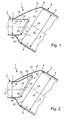
- Fig. 1 and 2 comprises an exhaust system 1 according to the invention and only partially shown at least one, here only in one end portion shown exhaust pipe 2 and a connected thereto catalyst or particulate filter unit 3, which is also shown only in a connected to the exhaust pipe 2 section.
- the exhaust system 1 is for attachment to an internal combustion engine, not shown here, which may be housed in particular in a motor vehicle, suitable and serves to dissipate the exhaust gases generated by the internal combustion engine.
- the catalyst or particle filter unit 3 comprises a housing 4, in which at least one monolith or at least one filter body 5 is accommodated.
- the monolith 5 or the filter body 5 is usually stored or positioned in the housing 4 with a bearing mat, not shown here.
- the filter body 5 may e.g. be a soot filter.
- the catalyst or particle filter unit 3 also has a funnel 6, which is connected with a first end 7 to the exhaust pipe 2 and with a second end 8 to the housing 4.
- the monolith or filter body 5 usually has a cross section 9, which is significantly larger than a cross section 10 of the exhaust pipe 2 in the region of the first funnel end 7. Accordingly, the funnel 6 widens from its first end 7 to its second end 8.
- the monolith or filter body cross section 9 is usually also larger than a cross section 11 of a mouth end 12 of the exhaust pipe 2.
- the monolith or filter body cross section 9 and the exhaust pipe cross section 10 are here transversely to the longitudinal center axis 13 of the monolith or filter body 5 or transversely to a Longitudinal center line 14 of the exhaust pipe 2 measured.
- the orifice cross section 11 is measured in a plane 21, in which the mouth end 12 extends.
- the exhaust pipe 2 is inserted concentrically with its mouth end 12 in the first funnel end 7, so that the longitudinal center line 14 of the exhaust pipe 2 coincides with a first longitudinal center axis 15 of the funnel 6, as long as the longitudinal center line 14 of the exhaust pipe 2 extends in a straight line. Furthermore, a second longitudinal central axis 16 of the funnel 6 coincides with the longitudinal central axis 13 of the monolith or of the filter body 5, since the monolith or filter body 5 is arranged concentrically with respect to the second funnel end 8.
- the funnel 6 is shaped so that its ends 7, 8 are inclined towards each other, i. the first longitudinal central axis 15 and the second longitudinal central axis 16 of the funnel 6 do not run parallel to one another but are inclined relative to one another.
- the exhaust pipe 2 does not axially connect with respect to the longitudinal central axis 13 of the monolith or of the filter body 5, but laterally against the funnel 6.
- the exhaust pipe 2 is inserted into the first funnel end 7, such that the mouth end 12 of the exhaust pipe 2 protrudes through the first funnel end 7 and projects into a funnel interior 17.
- the design of the exhaust pipe 2 and the geometry of the first funnel end 7 are coordinated so that the exhaust pipe 2 can be inserted from the monolith or filter body 5 away from the first funnel opening 7 into the funnel interior 17.
- a perpendicular to the longitudinal center line 14 of the exhaust pipe 2 measured cross section is constant and / or always equal to or smaller than an open inner cross section of the first funnel end 7.
- the exhaust pipe 2 may be formed so that its longitudinal center line 14 in the hopper interior 17 is rectilinear. Such an exhaust pipe 2 is particularly easy to produce. The insertion of the exhaust pipe 2 in the funnel 6 is characterized very simple.
- the exhaust pipe 2 is formed so that its longitudinal center line 14 within the hopper interior 17 has a curved course. Accordingly, this longitudinal center line 14 in the hopper interior 17 deviates from the first longitudinal central axis 15 in the first end 7 of the hopper 6.
- This course of the longitudinal center line 14 is achieved in that the exhaust pipe 2 is bent without changing its cross section in terms of shape and / or surface accordingly. It is important to ensure that the radii of curvature formed are chosen so that the exhaust pipe 2 in the desired manner in the first funnel end 7 can be inserted from the outside.
- this embodiment is somewhat more expensive to assemble, it opens up greater possibilities for designing the flow guidance in the interior of the catalyst or particle filter unit 3.
- the exhaust pipe 2 inserted laterally into the funnel 6 is used to influence the flow in the interior of the catalyst or particle filter unit 3.
- the mouth end 12 in the plane 21 whose normal or perpendicular to the longitudinal center line 14 is inclined at the point of intersection 19 with said mouth end plane 21.
- this inclination is - as here - chosen so that the muzzle end plane 21 extends substantially parallel to an end face 20 of the monolith and the filter body 5. That is, the normal or vertical of the mouth end plane 21 extends substantially parallel to the longitudinal center axis 13 of the monolith and the filter body 5.
- the flow guide from the mouth end 12 to the end face 20 of the monolith and the filter body 5 can be influenced and designed specifically.
- a flow guidance can be expedient in which a symmetrical, in particular uniform, distribution in the monolith or filter body cross-section 9 is formed with regard to gas temperature and / or flow rate.
- the in the Fig. 1 and 2 shown portion of the exhaust line 1 may be formed at the inlet of the catalyst or particulate filter unit 3, so that then the funnel 6 forms an inlet funnel 6.
- the catalyst or particle filter unit 3 may be designed according to the invention at its outlet, so that then the funnel 6 is designed as outlet funnel.
Landscapes
- Engineering & Computer Science (AREA)
- Chemical & Material Sciences (AREA)
- Combustion & Propulsion (AREA)
- Mechanical Engineering (AREA)
- General Engineering & Computer Science (AREA)
- Chemical Kinetics & Catalysis (AREA)
- Health & Medical Sciences (AREA)
- Toxicology (AREA)
- Exhaust Gas After Treatment (AREA)
Claims (3)
- Système pour gaz d'échappement pour un moteur à combustion, en particulier d'un véhicule automobile,- avec un tuyau d'échappement (2) relié à une unité de catalyseur ou de filtre à particules (3), qui, dans un boîtier (4), comprend au moins un monolithe (5) ou au moins un corps de filtre (5), dont la section transversale (9) est supérieure à une section transversale (11) du tuyau d'échappement (2) au niveau de l'une des embouchures (12) du tuyau d'échappement (2),- tandis que l'unité de catalyseur ou de filtre à particules (3) comporte un entonnoir (6) auquel est relié le tuyau d'échappement (2),- tandis que l'entonnoir (6) comporte un premier axe médian longitudinal (15) au niveau de sa première extrémité (7) raccordée au tuyau d'échappement (2), ainsi qu'un deuxième axe médian longitudinal (16) au niveau de sa deuxième extrémité tournée vers le monolithe (5) ou vers le corps de filtre (5), le deuxième axe médian longitudinal (16) étant incliné par rapport au premier (15),- tandis que l'embouchure (12) du tuyau d'échappement (2) est formée et dimensionnée de manière à pouvoir être introduite dans la première extrémité (7) de l'entonnoir,caractérisé en ce que- le tuyau d'échappement (2) s'engage librement par son embouchure (12) à l'intérieur (17) d'un entonnoir par la première extrémité (7) de l'entonnoir,- l'embouchure (12) se trouve dans un plan (21), dont la normale est inclinée par rapport à l'axe médian longitudinal (14) du tuyau d'échappement (2) dans l'embouchure (12),- l'embouchure (12) se trouve dans un plan (21) dont la normale est sensiblement parallèle à l'axe médian longitudinal (13) du monolithe (5) ou du corps de filtre (5).
- Système pour gaz d'échappement selon la revendication 1,
caractérisé en ce que
le tuyau d'échappement (2) comporte un axe médian longitudinal (14) qui se prolonge en ligne droite à l'intérieur (17) de l'entonnoir. - Système pour gaz d'échappement selon la revendication 1,
caractérisé en ce que
le tuyau d'échappement (2) présente un axe médian longitudinal (14) qui se prolonge en un coude arrondi ou incurvé ou angulaire à l'intérieur (17) de l'entonnoir.
Applications Claiming Priority (2)
| Application Number | Priority Date | Filing Date | Title |
|---|---|---|---|
| DE2003100384 DE10300384B4 (de) | 2003-01-09 | 2003-01-09 | Abgasanlage |
| DE10300384 | 2003-01-09 |
Publications (3)
| Publication Number | Publication Date |
|---|---|
| EP1437489A1 EP1437489A1 (fr) | 2004-07-14 |
| EP1437489B1 EP1437489B1 (fr) | 2006-11-29 |
| EP1437489B2 true EP1437489B2 (fr) | 2012-03-07 |
Family
ID=32478169
Family Applications (1)
| Application Number | Title | Priority Date | Filing Date |
|---|---|---|---|
| EP03024193A Expired - Fee Related EP1437489B2 (fr) | 2003-01-09 | 2003-10-21 | Système pour gaz d'échappement |
Country Status (2)
| Country | Link |
|---|---|
| EP (1) | EP1437489B2 (fr) |
| DE (2) | DE10300384B4 (fr) |
Families Citing this family (5)
| Publication number | Priority date | Publication date | Assignee | Title |
|---|---|---|---|---|
| KR101000224B1 (ko) | 2008-12-04 | 2010-12-10 | 현대자동차주식회사 | 차량용 촉매장치 |
| DE102010006829B4 (de) * | 2010-02-03 | 2013-08-14 | Benteler Automobiltechnik Gmbh | Abgasanlage |
| DE102011079906A1 (de) * | 2011-07-27 | 2013-01-31 | Bayerische Motoren Werke Aktiengesellschaft | Abgasanlage für ein Kraftfahrzeug |
| US10167765B2 (en) * | 2016-07-12 | 2019-01-01 | GM Global Technology Operations LLC | Exhaust gas seal |
| CN109404098A (zh) * | 2018-12-14 | 2019-03-01 | 东风汽车集团有限公司 | 一种横置后排增压发动机twc及gpf紧耦合热端催化器及排气系统 |
Citations (2)
| Publication number | Priority date | Publication date | Assignee | Title |
|---|---|---|---|---|
| DE4408130A1 (de) † | 1994-03-10 | 1995-09-14 | Bayerische Motoren Werke Ag | Vorrichtung zur Abgasreinigung bei Brennkraftmaschinen |
| DE19824428A1 (de) † | 1998-05-30 | 1999-12-02 | Daimler Chrysler Ag | Abgaskatalysatorkörper mit unterschiedlichen, parallelen Zellstrukturbereichen |
Family Cites Families (8)
| Publication number | Priority date | Publication date | Assignee | Title |
|---|---|---|---|---|
| SE450274B (sv) * | 1985-12-13 | 1987-06-15 | Saab Scania Ab | Katalysatorhus ingaende i ett fordons avgassystem |
| DE3903803A1 (de) * | 1989-02-09 | 1990-08-16 | Bayerische Motoren Werke Ag | Gehaeuse eines abgaskatalysators |
| DE4223648C2 (de) * | 1992-07-17 | 1996-02-01 | Zeuna Staerker Kg | Katalytische Abgasreinigungsvorrichtung |
| DE4440160C2 (de) * | 1993-12-03 | 1997-02-27 | Gen Motors Corp | Katalysator-Diffusor |
| DE9421332U1 (de) * | 1994-06-16 | 1995-10-05 | Boysen Friedrich Gmbh Co Kg | Vorrichtung zur katalytischen Reinigung bzw. Zerlegung von heißen Abgasen |
| JP3294036B2 (ja) * | 1995-01-26 | 2002-06-17 | 日本碍子株式会社 | ハニカム触媒コンバータ |
| WO2000039437A1 (fr) * | 1998-12-28 | 2000-07-06 | Corning Incorporated | Convertisseur utilise dans le traitement de gaz |
| DE10002218A1 (de) * | 2000-01-20 | 2001-07-26 | Eberspaecher J Gmbh & Co | Abgaskatalysator |
-
2003
- 2003-01-09 DE DE2003100384 patent/DE10300384B4/de not_active Expired - Fee Related
- 2003-10-21 EP EP03024193A patent/EP1437489B2/fr not_active Expired - Fee Related
- 2003-10-21 DE DE50305832T patent/DE50305832D1/de not_active Expired - Lifetime
Patent Citations (2)
| Publication number | Priority date | Publication date | Assignee | Title |
|---|---|---|---|---|
| DE4408130A1 (de) † | 1994-03-10 | 1995-09-14 | Bayerische Motoren Werke Ag | Vorrichtung zur Abgasreinigung bei Brennkraftmaschinen |
| DE19824428A1 (de) † | 1998-05-30 | 1999-12-02 | Daimler Chrysler Ag | Abgaskatalysatorkörper mit unterschiedlichen, parallelen Zellstrukturbereichen |
Also Published As
| Publication number | Publication date |
|---|---|
| DE10300384B4 (de) | 2005-12-01 |
| DE50305832D1 (de) | 2007-01-11 |
| EP1437489B1 (fr) | 2006-11-29 |
| DE10300384A1 (de) | 2004-07-29 |
| EP1437489A1 (fr) | 2004-07-14 |
Similar Documents
| Publication | Publication Date | Title |
|---|---|---|
| EP3216992B1 (fr) | Mélangeur | |
| EP2161423B1 (fr) | Installation de gaz d'échappement pour véhicules diesel dotés d'un catalyseur SCR | |
| EP2233709B1 (fr) | Dispositif de traitement de gaz d'échappement | |
| EP3478947B1 (fr) | Dispositif mélangeur pour un système de post-traitement des gaz d'échappement d'un véhicule à moteur, système de post-traitement des gaz d'échappement et véhicule à moteur | |
| DE102004020138B4 (de) | Reduktionsmittelzugabesystem | |
| DE102008031136B4 (de) | Abgasbehandlungseinrichtung | |
| EP2027372B1 (fr) | Filtre à flux secondaire avec rendement de filtre amélioré | |
| WO2008107151A1 (fr) | Dispositif de post-traitement des gaz d'échappement d'un véhicule automobile | |
| EP4086439B1 (fr) | Module de traitement des gaz d'échappement | |
| EP3412879B1 (fr) | Dispositif de post-traitement de gaz d'échappement d'un moteur à combustion interne d'un véhicule automobile | |
| EP1437489B2 (fr) | Système pour gaz d'échappement | |
| DE102018107766A1 (de) | Abgasanlage und Mischerbaugruppe für eine Abgasanlage | |
| EP3597997B1 (fr) | Appareil chauffant pour véhicule | |
| DE102004018693B4 (de) | Abgasanlage | |
| EP3109423B1 (fr) | Silencieux d'échappement | |
| DE4212505C1 (en) | Double wall pipe providing intermediate chamber for lambda sensor support - is insulated to prevent loss of heat from exhaust gas of motor vehicle so that catalyser can be effective from cold start | |
| EP3327261B1 (fr) | Dispositif de traitement de gaz d'échappement | |
| EP0561019B1 (fr) | Dispositif pour le positionnement d'un boîtier intérieur dans le boîtier d'une installation d'échappement pour véhicules | |
| EP3851646B1 (fr) | Mélangeur gaz/gaz permettant d'introduire du gaz au flux de gaz d'échappement d'un moteur à combustion interne | |
| EP0451662B1 (fr) | Brûleur récupérateur | |
| EP4105456B1 (fr) | Silencieux pour un système d'échappement d'un moteur à combustion interne | |
| EP3514342B1 (fr) | Amortisseur de bruit | |
| DE1294393B (de) | Auspufftopf fuer Kraftfahrzeuge | |
| WO2008025600A1 (fr) | Ensemble de filtration, utilisé en particulier pour un système d'échappement d'un moteur à combustion interne | |
| DE102005051920B4 (de) | Rohrleitungsstück für eine Abgasleitung |
Legal Events
| Date | Code | Title | Description |
|---|---|---|---|
| PUAI | Public reference made under article 153(3) epc to a published international application that has entered the european phase |
Free format text: ORIGINAL CODE: 0009012 |
|
| AK | Designated contracting states |
Kind code of ref document: A1 Designated state(s): AT BE BG CH CY CZ DE DK EE ES FI FR GB GR HU IE IT LI LU MC NL PT RO SE SI SK TR |
|
| AX | Request for extension of the european patent |
Extension state: AL LT LV MK |
|
| 17P | Request for examination filed |
Effective date: 20040727 |
|
| AKX | Designation fees paid |
Designated state(s): DE FR IT |
|
| GRAP | Despatch of communication of intention to grant a patent |
Free format text: ORIGINAL CODE: EPIDOSNIGR1 |
|
| GRAS | Grant fee paid |
Free format text: ORIGINAL CODE: EPIDOSNIGR3 |
|
| GRAA | (expected) grant |
Free format text: ORIGINAL CODE: 0009210 |
|
| AK | Designated contracting states |
Kind code of ref document: B1 Designated state(s): DE FR IT |
|
| REF | Corresponds to: |
Ref document number: 50305832 Country of ref document: DE Date of ref document: 20070111 Kind code of ref document: P |
|
| ET | Fr: translation filed | ||
| PLBI | Opposition filed |
Free format text: ORIGINAL CODE: 0009260 |
|
| PLAX | Notice of opposition and request to file observation + time limit sent |
Free format text: ORIGINAL CODE: EPIDOSNOBS2 |
|
| 26 | Opposition filed |
Opponent name: FRIEDRICH BOYSEN GMBH & CO. KG Effective date: 20070829 |
|
| PLBB | Reply of patent proprietor to notice(s) of opposition received |
Free format text: ORIGINAL CODE: EPIDOSNOBS3 |
|
| APBM | Appeal reference recorded |
Free format text: ORIGINAL CODE: EPIDOSNREFNO |
|
| APBP | Date of receipt of notice of appeal recorded |
Free format text: ORIGINAL CODE: EPIDOSNNOA2O |
|
| APAH | Appeal reference modified |
Free format text: ORIGINAL CODE: EPIDOSCREFNO |
|
| APBQ | Date of receipt of statement of grounds of appeal recorded |
Free format text: ORIGINAL CODE: EPIDOSNNOA3O |
|
| APBU | Appeal procedure closed |
Free format text: ORIGINAL CODE: EPIDOSNNOA9O |
|
| RIC2 | Information provided on ipc code assigned after grant |
Ipc: F01N 3/28 20060101AFI20111004BHEP Ipc: F01N 13/18 20100101ALI20111004BHEP |
|
| PUAH | Patent maintained in amended form |
Free format text: ORIGINAL CODE: 0009272 |
|
| STAA | Information on the status of an ep patent application or granted ep patent |
Free format text: STATUS: PATENT MAINTAINED AS AMENDED |
|
| 27A | Patent maintained in amended form |
Effective date: 20120307 |
|
| AK | Designated contracting states |
Kind code of ref document: B2 Designated state(s): DE FR IT |
|
| REG | Reference to a national code |
Ref country code: DE Ref legal event code: R102 Ref document number: 50305832 Country of ref document: DE Effective date: 20120307 |
|
| REG | Reference to a national code |
Ref country code: DE Ref legal event code: R082 Ref document number: 50305832 Country of ref document: DE Representative=s name: BRP RENAUD & PARTNER, DE |
|
| REG | Reference to a national code |
Ref country code: DE Ref legal event code: R082 Ref document number: 50305832 Country of ref document: DE Representative=s name: BRP RENAUD & PARTNER, DE Effective date: 20131022 Ref country code: DE Ref legal event code: R081 Ref document number: 50305832 Country of ref document: DE Owner name: EBERSPAECHER EXHAUST TECHNOLOGY GMBH & CO. KG, DE Free format text: FORMER OWNER: J. EBERSPAECHER GMBH & CO. KG, 73730 ESSLINGEN, DE Effective date: 20131022 Ref country code: DE Ref legal event code: R082 Ref document number: 50305832 Country of ref document: DE Representative=s name: BRP RENAUD UND PARTNER MBB RECHTSANWAELTE PATE, DE Effective date: 20131022 Ref country code: DE Ref legal event code: R082 Ref document number: 50305832 Country of ref document: DE Representative=s name: BRP RENAUD UND PARTNER MBB, DE Effective date: 20131022 |
|
| REG | Reference to a national code |
Ref country code: FR Ref legal event code: CD Owner name: EBERSPACHER CLIMATE CONTROL SYSTEMS GMBH & CO. KG Effective date: 20131129 |
|
| REG | Reference to a national code |
Ref country code: FR Ref legal event code: TP Owner name: EBERSPACHER EXHAUST TECHNOLOGY GMBH & CO. KG, DE Effective date: 20140204 |
|
| REG | Reference to a national code |
Ref country code: FR Ref legal event code: PLFP Year of fee payment: 13 |
|
| REG | Reference to a national code |
Ref country code: FR Ref legal event code: PLFP Year of fee payment: 14 |
|
| REG | Reference to a national code |
Ref country code: FR Ref legal event code: PLFP Year of fee payment: 15 |
|
| REG | Reference to a national code |
Ref country code: FR Ref legal event code: PLFP Year of fee payment: 16 |
|
| PGFP | Annual fee paid to national office [announced via postgrant information from national office to epo] |
Ref country code: IT Payment date: 20201030 Year of fee payment: 18 |
|
| REG | Reference to a national code |
Ref country code: DE Ref legal event code: R081 Ref document number: 50305832 Country of ref document: DE Owner name: PUREM GMBH, DE Free format text: FORMER OWNER: EBERSPAECHER EXHAUST TECHNOLOGY GMBH & CO. KG, 66539 NEUNKIRCHEN, DE |
|
| PGFP | Annual fee paid to national office [announced via postgrant information from national office to epo] |
Ref country code: DE Payment date: 20211020 Year of fee payment: 19 |
|
| PGFP | Annual fee paid to national office [announced via postgrant information from national office to epo] |
Ref country code: FR Payment date: 20211021 Year of fee payment: 19 |
|
| REG | Reference to a national code |
Ref country code: DE Ref legal event code: R119 Ref document number: 50305832 Country of ref document: DE |
|
| PG25 | Lapsed in a contracting state [announced via postgrant information from national office to epo] |
Ref country code: IT Free format text: LAPSE BECAUSE OF NON-PAYMENT OF DUE FEES Effective date: 20211031 |
|
| PG25 | Lapsed in a contracting state [announced via postgrant information from national office to epo] |
Ref country code: FR Free format text: LAPSE BECAUSE OF NON-PAYMENT OF DUE FEES Effective date: 20221031 Ref country code: DE Free format text: LAPSE BECAUSE OF NON-PAYMENT OF DUE FEES Effective date: 20230503 |