EP3327199A1 - System und verfahren zum nachverfolgen von fräsgut - Google Patents
System und verfahren zum nachverfolgen von fräsgut Download PDFInfo
- Publication number
- EP3327199A1 EP3327199A1 EP17202991.0A EP17202991A EP3327199A1 EP 3327199 A1 EP3327199 A1 EP 3327199A1 EP 17202991 A EP17202991 A EP 17202991A EP 3327199 A1 EP3327199 A1 EP 3327199A1
- Authority
- EP
- European Patent Office
- Prior art keywords
- milled material
- marking
- data
- milled
- milling
- Prior art date
- Legal status (The legal status is an assumption and is not a legal conclusion. Google has not performed a legal analysis and makes no representation as to the accuracy of the status listed.)
- Granted
Links
Images



Classifications
-
- E—FIXED CONSTRUCTIONS
- E21—EARTH OR ROCK DRILLING; MINING
- E21C—MINING OR QUARRYING
- E21C39/00—Devices for testing in situ the hardness or other properties of minerals, e.g. for giving information as to the selection of suitable mining tools
-
- G—PHYSICS
- G06—COMPUTING OR CALCULATING; COUNTING
- G06K—GRAPHICAL DATA READING; PRESENTATION OF DATA; RECORD CARRIERS; HANDLING RECORD CARRIERS
- G06K17/00—Methods or arrangements for effecting co-operative working between equipments covered by two or more of main groups G06K1/00 - G06K15/00, e.g. automatic card files incorporating conveying and reading operations
-
- G—PHYSICS
- G06—COMPUTING OR CALCULATING; COUNTING
- G06Q—INFORMATION AND COMMUNICATION TECHNOLOGY [ICT] SPECIALLY ADAPTED FOR ADMINISTRATIVE, COMMERCIAL, FINANCIAL, MANAGERIAL OR SUPERVISORY PURPOSES; SYSTEMS OR METHODS SPECIALLY ADAPTED FOR ADMINISTRATIVE, COMMERCIAL, FINANCIAL, MANAGERIAL OR SUPERVISORY PURPOSES, NOT OTHERWISE PROVIDED FOR
- G06Q10/00—Administration; Management
- G06Q10/08—Logistics, e.g. warehousing, loading or distribution; Inventory or stock management
- G06Q10/087—Inventory or stock management, e.g. order filling, procurement or balancing against orders
-
- E—FIXED CONSTRUCTIONS
- E01—CONSTRUCTION OF ROADS, RAILWAYS, OR BRIDGES
- E01C—CONSTRUCTION OF, OR SURFACES FOR, ROADS, SPORTS GROUNDS, OR THE LIKE; MACHINES OR AUXILIARY TOOLS FOR CONSTRUCTION OR REPAIR
- E01C23/00—Auxiliary devices or arrangements for constructing, repairing, reconditioning, or taking-up road or like surfaces
- E01C23/06—Devices or arrangements for working the finished surface; Devices for repairing or reconditioning the surface of damaged paving; Recycling in place or on the road
- E01C23/08—Devices or arrangements for working the finished surface; Devices for repairing or reconditioning the surface of damaged paving; Recycling in place or on the road for roughening or patterning; for removing the surface down to a predetermined depth high spots or material bonded to the surface, e.g. markings; for maintaining earth roads, clay courts or like surfaces by means of surface working tools, e.g. scarifiers, levelling blades
- E01C23/085—Devices or arrangements for working the finished surface; Devices for repairing or reconditioning the surface of damaged paving; Recycling in place or on the road for roughening or patterning; for removing the surface down to a predetermined depth high spots or material bonded to the surface, e.g. markings; for maintaining earth roads, clay courts or like surfaces by means of surface working tools, e.g. scarifiers, levelling blades using power-driven tools, e.g. vibratory tools
- E01C23/088—Rotary tools, e.g. milling drums
-
- G—PHYSICS
- G01—MEASURING; TESTING
- G01B—MEASURING LENGTH, THICKNESS OR SIMILAR LINEAR DIMENSIONS; MEASURING ANGLES; MEASURING AREAS; MEASURING IRREGULARITIES OF SURFACES OR CONTOURS
- G01B7/00—Measuring arrangements characterised by the use of electric or magnetic techniques
- G01B7/02—Measuring arrangements characterised by the use of electric or magnetic techniques for measuring length, width or thickness
- G01B7/06—Measuring arrangements characterised by the use of electric or magnetic techniques for measuring length, width or thickness for measuring thickness
-
- G—PHYSICS
- G06—COMPUTING OR CALCULATING; COUNTING
- G06Q—INFORMATION AND COMMUNICATION TECHNOLOGY [ICT] SPECIALLY ADAPTED FOR ADMINISTRATIVE, COMMERCIAL, FINANCIAL, MANAGERIAL OR SUPERVISORY PURPOSES; SYSTEMS OR METHODS SPECIALLY ADAPTED FOR ADMINISTRATIVE, COMMERCIAL, FINANCIAL, MANAGERIAL OR SUPERVISORY PURPOSES, NOT OTHERWISE PROVIDED FOR
- G06Q50/00—Information and communication technology [ICT] specially adapted for implementation of business processes of specific business sectors, e.g. utilities or tourism
- G06Q50/08—Construction
-
- E—FIXED CONSTRUCTIONS
- E21—EARTH OR ROCK DRILLING; MINING
- E21C—MINING OR QUARRYING
- E21C25/00—Cutting machines, i.e. for making slits approximately parallel or perpendicular to the seam
- E21C25/06—Machines slitting solely by one or more cutting rods or cutting drums which rotate, move through the seam, and may or may not reciprocate
- E21C25/10—Rods; Drums
-
- G—PHYSICS
- G01—MEASURING; TESTING
- G01V—GEOPHYSICS; GRAVITATIONAL MEASUREMENTS; DETECTING MASSES OR OBJECTS; TAGS
- G01V8/00—Prospecting or detecting by optical means
- G01V8/10—Detecting, e.g. by using light barriers
- G01V8/12—Detecting, e.g. by using light barriers using one transmitter and one receiver
Definitions
- the invention relates to a system according to the preamble of claim 1 and a method for tracking milled material according to the preamble of claim 13.
- Milling machines are known with which sections of a floor covering can be milled in a milling operation. Furthermore, the milled material removed during milling of the section of the floor covering is loaded onto a means of transport, in particular a truck, and transported away. The transported away on the transport milled material is stored at a storage location. It is known to detect data signals concerning the milled material with a detection device. For example, the depth of cut and the removed milling volume are recorded.
- the object of the present invention is therefore to provide a system and a method with which the recycling possibilities of the milled material can be improved.
- the invention advantageously provides that the detection device transmits the data signals relating to the milled material to an identification device and the identification device identifies the milled material stored on the means of transport or the transport means loaded with the milled material with a marking agent depending on the data signals relating to the milled material.
- the data signals relating to the milled material can be assigned to a milled material.
- the transport may be, for example, a truck or tractor-mounted tractor.
- the marking agent can be transported away with the stored on the transport milled material with the transport.
- the marking agent may be a paint that can be applied to the milled material stored on the means of transport.
- the marking device can apply different colors to the milled material.
- the milled material can be determined, for example, whether the milled material contains certain materials, for example. It can thus be determined by means of the detection device, for example, whether materials are included in the milled material, which are classified as hazardous waste. Depending on this, a specific color can be selected.
- the tagging means may be a tagged data storage device.
- the data storage device may be an electronic data storage device to which the tag data is transferable from the tag device.
- the marking data may be the data signals concerning the milled material.
- the marking device or the detection device can determine the marking data on the basis of the data signals relating to the milled material.
- the electronic data storage device may be a transponder or an RFID chip.
- the tagging device may transmit the tagging data to the tagging means via a wireless connection, the tagging means being the data storage device.
- the marking of the material can be done continuously. For example, the entire overloaded milled material can be marked with marking agents. Alternatively, the labeling can only be made if the loading process is nearing completion. For example, the transmission of a marking agent may occur when the truck is almost fully loaded, so that only a single marking means is used to identify the entire loaded material. However, all intermediate stages are possible. Thus, at the beginning or at the end of the loading, a marking agent may be provided or else, for example, per predetermined quantity, e.g. per ton of milled material a marking agent.
- the data signals relating to the milled material may relate to the material properties of the milled material, in particular the material of the milled material and / or position data of the milled section of the floor covering.
- the location data of the milled section of the floor covering may also be data signals concerning the material properties of the milled material. It can be determined, for example, which highway section is being milled. It can be known which material has been installed in the motorway section, so that it can be determined on the basis of the motorway section which material has been installed.
- the flooring usually has a cover, a binder and a support layer.
- the known information regarding the material may be stored in a database (e.g., locally on the milling machine or outside the milling machine), or this information may be input by an operator of the milling machine.
- the location data can also be determined using GPS coordinates. These data signals relating to the material properties of the milled material can then be detected by the detection device.
- samples of the milled material can be taken and evaluated directly or later.
- the data signals relating to the material properties of the milled material can also be data signals which relate to the number or the name of such a sample.
- Material properties of the milled material can be of interest for disposal and recycling. For example, it may be important to know whether tar is contained in the milled material, since tar must be disposed of separately. Furthermore, the knowledge regarding the bitumen content in the milled material can be relevant for recycling.
- the milled material originates can be of importance as a material property.
- material from a base course during reuse may not be used to make an asphalt mixture to be used as a decking in a new road construction.
- the milled material on the other hand a topcoat can be prepared to an asphalt mixture, is used as a base course in a new road construction.
- the data signals concerning the milled material may be operating parameters of the milling machine or data or data signals which are determined by means of the operating parameters, location data or entered information. Thus, both the directly determined or input data or data signals and data derived therefrom can be detected as data signals concerning the milled material.
- the derived from the determined or input data or data signals data that can also represent information about how the milled material is to be marked by the marking device. Information as to how the milled material is to be identified by the marking device can thus also be the data signals relating to the milled material in the sense of the invention.
- Operating parameters may in particular be milling depth, abraded milling volume, feed rate, milling roll speed, ratio between feed and Fräswalzenfitiere, used milling drum, output torque / power of the drive motor of the milling machine or supplied during the milling process for cooling the milling tools amount of water.
- it can be detected whether the mill is working in synchronous or reverse milling (direction of rotation of the milling drum in the same direction or opposite to the direction of rotation of the drives).
- the data signals concerning the milled material can also be mass and / or volume of the milled material loaded onto the truck.
- These operating parameters can be used to determine data or data signals. These may be material properties of the milled material, such as, for example, the particle size distribution in the milled material, fines / coarse fractions.
- the physical properties can be derived, for example, from the ratio between feed rate and milling roll speed or used milling drum.
- the floor covering has, for example, a cover layer, a binder layer and a base layer, which generally have different layer thicknesses.
- the router location data can be correlated to allow more accurate conclusions about the layer being milled.
- the data relating to the milled data signals are transmitted from the detection device to a marking device and depending on the transmitted, the milled data signals relating to the stored milled material or loaded with the milled material of the marking device with a marking agent is marked.
- the transport may be, for example, a truck or tractor-mounted tractor.
- the marking agent can be removed with the stored on the transport milled material with the means of transport.
- the marking means may be a color or a data storage device.
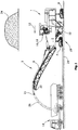
- a system 3 for tracking milled material is shown.
- the system 3 has a milling machine 1 for milling a section 28 of a floor covering 29 in a milling operation.
- the floor covering 29 is milled and the abraded milled material 26 is loaded via at least one conveyor belt 8 onto a transport means designed as a lorry 14 in the present exemplary embodiments.
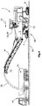
- the milled 26 loaded on the truck 14 can be stored at a storage location 24.
- the milling machine 1 may have at least one machine frame 2. Furthermore, the milling machine has a height-adjustable milling drum 10 for processing the floor covering 29, wherein in a milling operation the milling drum 10 processes the floor covering 29.
- the milling drum 10 is driven by a drive unit.
- the drive unit is preferably a drive motor, in particular an internal combustion engine.
- the milling machine 1 has in the working direction 12 front and rear driving devices 4, 6. These driving devices 4, 6 may be wheels or crawler tracks.
- the driving devices 4, 6 can be connected via lifting columns to the machine frame 2. With the help of the lifting columns, the milling machine 1 or the machine frame 2 can be adjusted in height relative to the floor covering 29. By adjusting the lifting columns of the machine frame 2 is adjusted in height and thus also the mounted in the machine frame 2 milling drum 10 height-adjusted. Alternatively or additionally, the milling drum 10 can be adjusted in height relative to the machine frame 2.
- the detection device 18 is arranged on the milling machine 1.
- the detection device 18 can detect the data items concerning the milled material. These can be, for example, operating parameters of the milling machine 1 or data or data signals which are determined by means of the operating parameters.
- Operating parameters may be milling depth, milling volume removed, milling depth, feed rate, milling roll speed, ratio between feed and Fräswalzenfitiere, used milling drum, output torque / power of the drive motor of the milling machine or added amount of water.
- it can be determined whether the mill is working in synchronous or reverse milling.
- the amount or the volume or the mass of the removed milled material can be determined or indirect conclusions about the material properties of the milled material can be drawn. These material properties or determined data can be detected as data items concerning the milled material.
- the detection device 18 can also detect further data signals, which can not be determined on the basis of the operating parameters, of the material to be milled as the milled material. For example, the location data of the milled section 28 of the floor covering 29 can be detected. It can be known which material has been installed in this section 28, so that conclusions can be drawn on the material on the basis of the location data. Additionally or alternatively, material properties of the milled material can be entered or stored, so that the detection device 18 can detect these material properties of the milled material.
- information regarding the just milled layer of the flooring 29 can be derived from the operating parameters of the milling machine 1 or entered. This derived or input information can be detected as the milled data signals.
- the operating parameters can be detected by the detection device 18 via the control device 16 of the milling machine 1.
- the detection device 18 can also be arranged externally from the milling machine 1.
- the system 3 for tracking milled material also has a marking device 20.
- the detection device 18 transmits the data relating to the milled data signals to the marking device 20.
- the marking device 20 is dependent on the transmitted, the milled data data concerned stored on the truck 14 milled 26 or the truck 14 with a marking means 21st
- the marking means 21 may be a data storage device.
- Tag data may be transferred to the data storage device.
- the marking data may be the data signals relating to the milled material or may be data which are determined on the basis of the data signals relating to the milled material.
- specific materials can be determined on the basis of the data signals relating to the milled material.
- These materials can be transmitted as marking data, for example, to the marking means 21 designed as a data storage device.
- a term derived therefrom such as "hazardous waste”
- the data relevant to the milled data signals can then be stored such that they can be assigned, for example, this number.
- Fig. 3 an alternative embodiment is shown.
- the marking device 20 identifies the milled material 26 deposited on the truck 14 with a marking means 21 '.
- the marking means 21 ' may be a color in the illustrated embodiment.
- the marking device 20 can apply different colors to the milled material 26 depending on the data signals concerning the milled material.
- the truck has a data storage device.
- the tag device 20 transfers tag data to the data storage device.
- the data storage device becomes a marking means 21.
- the truck 14 loaded with the milled material is marked with a marking means 21.
- the marking means 21 can be read out.
- the marking device 20 can also be a printer, for example, and print specific information on a paper depending on the data signals concerning the milled material.
- This paper can represent a marking agent, wherein the marking agent can be given to the truck 14 loaded with the milled material and thus characterizes the truck 14 loaded with the milled material.
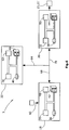
- the detection device 18 and the identification device 20 are shown.
- the detection device 18 as well as the identification device 20 may be computer systems. These may include processors 30, 32 and / or computer-readable memories 36, 38 and / or databases 42, 44.
- the detection device and / or the identification device 20 can also have a user interface 48, 50.
- the detection device 18 can detect data signals 60.
- the data signals 60 may be detected by the controller 16 or may be input. Alternatively, the detection device 18 can also directly receive the data signals 60 from sensors of the milling machine 1. From the data signals 60, the detection device 18 can determine the data concerning the milled data. If the data signals 60 include, for example, the milling drum rotational speed and the feed rate of the milling machine, these data signals 60 can be correlated by means of the processor 30 and / or database 42 with a grain size distribution of the milling material. If the data signals 60 include GPS coordinates that are representative of the milled section 28 of the floor covering, the material properties of the material present at this section 28 can be stored in the database 42.
- the detection device 18 may transmit the determined data or data signals to the tag device 20 via a data link 72.
- the data signals 60 can be transmitted to the identification device 20 as data items relating to the milled material.
- the marking device 20 may mark the milled material stored on the truck 14 or the truck loaded with the milled material with a marking means 21, 21 '.
- the marking device 20 can select the marking means 21, 21 '. If the marking means 21, 21 'is a data storage device, the marking device 20 can transmit certain marking data to the marking means 21 depending on the data signals concerning the milled material. In this way it can be tracked, which milled material is transported on the appropriate truck.
- the detection device 18 and the identification device 20 may also be formed as a unit.
- Fig. 6 another embodiment is shown. This is different from Fig. 5 in that a documentation device 22 is provided.
- this documentation device 22 the data relevant to the milled data can be stored. Also, information can be deposited by the marking device 20, with which marking means 21, 21 ', the corresponding stored milled material is marked. This information relating to the marking means and the data signals relating to the milled material can be linked in the documentation device 22.
- the documentation device 22 may also comprise a processor 34 and / or a computer-readable memory 40 and / or a database 46 and / or an IO platform or module 52, which typically has a user interface.
Landscapes
- Engineering & Computer Science (AREA)
- Business, Economics & Management (AREA)
- General Physics & Mathematics (AREA)
- Physics & Mathematics (AREA)
- Economics (AREA)
- Theoretical Computer Science (AREA)
- Mining & Mineral Resources (AREA)
- General Business, Economics & Management (AREA)
- Human Resources & Organizations (AREA)
- Tourism & Hospitality (AREA)
- Strategic Management (AREA)
- Marketing (AREA)
- Architecture (AREA)
- Civil Engineering (AREA)
- Structural Engineering (AREA)
- Mechanical Engineering (AREA)
- Operations Research (AREA)
- Accounting & Taxation (AREA)
- Entrepreneurship & Innovation (AREA)
- Development Economics (AREA)
- Finance (AREA)
- Quality & Reliability (AREA)
- Health & Medical Sciences (AREA)
- General Health & Medical Sciences (AREA)
- Primary Health Care (AREA)
- Geology (AREA)
- General Life Sciences & Earth Sciences (AREA)
- Life Sciences & Earth Sciences (AREA)
- Geochemistry & Mineralogy (AREA)
- Road Repair (AREA)
- General Factory Administration (AREA)
- Processing Of Solid Wastes (AREA)
Abstract
Description
- Die Erfindung betrifft ein System nach dem Oberbegriff des Anspruchs 1 sowie ein Verfahren zum Nachverfolgen von Fräsgut nach dem Oberbegriff des Anspruchs 13.
- Es sind Fräsmaschinen bekannt, mit denen Abschnitte eines Bodenbelags in einem Fräsbetrieb gefräst werden können. Ferner wird das beim Fräsen des Abschnitts des Bodenbelags abgetragene Fräsgut auf ein Transportmittel, insbesondere einem LKW geladen und abtransportiert. Das auf dem Transportmittel abtransportierte Fräsgut wird an einer Ablagestelle abgelegt. Es ist bekannt mit einer Erfassungseinrichtung das Fräsgut betreffende Datensignale zu erfassen. Dabei werden beispielsweise Frästiefe und abgetragenes Fräsvolumen erfasst.
- Es besteht jedoch zunehmend Bedarf, das abgetragene Fräsgut wieder zu recyceln.
- Aufgabe der vorliegenden Erfindung ist es daher, ein System und ein Verfahren zu schaffen, mit dem die Recyclingmöglichkeiten des Fräsguts verbessert werden kann.
- Zur Lösung dieser Aufgabe dienen die Merkmale der Ansprüche 1 und 13.
- Die Erfindung sieht in vorteilhafter Weise vor, dass die Erfassungseinrichtung die das Fräsgut betreffenden Datensignale an eine Kennzeichnungseinrichtung überträgt und die Kennzeichnungseinrichtung abhängig von den übertragenen das Fräsgut betreffenden Datensignale das auf dem Transportmittel abgelegte Fräsgut oder das mit dem Fräsgut belade Transportmittel mit einem Markierungsmittel kennzeichnet.
- Auf diese Weise können die das Fräsgut betreffenden Datensignale einem Fräsgut zugeordnet werden.
- Das Transportmittel kann beispielsweise ein LKW oder mit einem Anhänger versehener Traktor sein.
- Das Markierungsmittel kann mit dem auf dem Transportmittel abgelegten Fräsgut mit dem Transportmittel abtransportierbar sein.
- Das Markierungsmittel kann eine Farbe sein, die auf das auf dem Transportmittel abgelegten Fräsgut aufbringbar ist.
- Die Kennzeichnungseinrichtung kann abhängig von den das Fräsgut betreffenden Datensignalen unterschiedliche Farben auf das Fräsgut aufbringen.
- Abhängig von den das Fräsgut betreffenden Datensignalen kann beispielsweise bestimmt werden, ob das Fräsgut beispielsweise bestimmte Materialien enthält. Es kann somit mittels der Erfassungseinrichtung bestimmt werden, ob beispielsweise Materialien in dem Fräsgut enthalten sind, die als Sondermüll eingeordnet werden. Abhängig davon kann eine bestimmte Farbe gewählt werden.
- Alternativ kann das Markierungsmittel eine mit Markierungsdaten versehene Datenspeichereinrichtung sein.
- Die Datenspeichereinrichtung kann eine elektronische Datenspeichereinrichtung sein, auf die die Markierungsdaten von der Kennzeichnungseinrichtung übertragbar sind.
- Die Markierungsdaten können die das Fräsgut betreffenden Datensignale sein.
- Alternativ kann die Kennzeichnungseinrichtung oder die Erfassungseinrichtung anhand der das Fräsgut betreffenden Datensignale die Markierungsdaten ermitteln.
- Die elektronische Datenspeichereinrichtung kann ein Transponder oder ein RFID-Chip sein.
- Die Kennzeichnungseinrichtung kann die Markierungsdaten mittels einer drahtlosen Verbindung auf das Markierungsmittel übertragen, wobei das Markierungsmittel die Datenspeichereinrichtung ist.
- Die Markierung des Fräsguts kann kontinuierlich erfolgen. Beispielsweise kann das gesamte überladene Fräsgut mit Markierungsmitteln gekennzeichnet werden. Alternativ kann die Kennzeichnung auch nur erfolgen wenn der Beladevorgang kurz vor dem Abschluss steht. Beispielsweise kann die Übertragung eines Markierungsmittels erfolgen wenn der LKW nahezu voll beladen ist, so dass lediglich ein einzelnes Markierungsmittel zur Kennzeichnung des gesamten verladenen Materials dient. Es sind jedoch auch alle Zwischenstufen möglich. So kann jeweils bei Begin oder am Ende der Beladung ein Markierungsmittel vorgesehen sein oder auch beispielsweise pro vorbestimmter Menge, so z.B. je Tonne Fräsgut ein Markierungsmittel.
- Die das Fräsgut betreffenden Datensignale können die Materialeigenschaften des Fräsguts betreffen, insbesondere das Material des Fräsguts und/oder Positionsdaten des gefrästen Abschnitts des Bodenbelags sein.
- Bezüglich der die Materialeigenschaften des Fräsguts betreffenden Datensignale können dies Datensignale sein, die direkt die Materialeigenschaften des Materials beschreiben oder Datensignale sein, mit denen Rückschlüsse auf das Material gezogen werden können. Daher können auch im Sinne der Erfindung die Ortsdaten des gefrästen Abschnitts des Bodenbelags die Materialeigenschaften des Fräsguts betreffende Datensignale sein. Es kann beispielsweise ermittelt werden, welcher Autobahnabschnitt gefräst wird. Es kann bekannt sein, welches Material in dem Autobahnabschnitt verbaut worden ist, so dass anhand des Autobahnabschnitts ermittelt werden kann welches Material verbaut worden ist.
- Es kann beispielsweise bekannt sein, welcher Asphalt verbaut worden ist oder welche Zusammensetzung das verbaute Material hat. Auch kann bekannt sein welches Material in unterschiedlichen Schichten des Bodenbelags verbaut worden ist. Der Bodenbelag weist in der Regel eine Deck-, eine Binder- und eine Tragschicht auf. Die bekannten Informationen bezüglich des Materials können in einer Datenbank (z.B. lokal auf der Fräsmaschine oder außerhalb der Fräsmaschine) hinterlegt sein oder es können diese Informationen von einem Bediener der Fräsmaschine eingegeben werden. Die Ortsdaten können auch anhand von GPS Koordinaten ermittelt werden. Diese die Materialeigenschaften des Fräsguts betreffenden Datensignale können dann von der Erfassungseinrichtung erfasst werden.
- Auch können beispielsweise Proben des abgefrästen Materials genommen werden und direkt oder erst später ausgewertet werden. Im Sinne der Erfindung können die die Materialeigenschaften des Fräsguts betreffenden Datensignale auch Datensignale sein, die die Nummer oder den Namen einer solchen Probe betreffen.
- Materialeigenschaften des Fräsguts können für die Entsorgung und das Recycling interessant sein. Beispielsweise kann es wichtig sein, dass bekannt ist, ob Teer in dem Fräsgut enthalten ist, da Teer gesondert entsorgt werden muss. Ferner kann für das Recycling das Wissen bezüglich der Bitumenanteile im Fräsgut relevant sein.
- Bereits die Information aus welcher Schicht des Straßenaufbaus das Fräsgut stammt kann als Materialeigenschaft von Bedeutung sein. Beispielsweise darf Material aus einer Tragschicht im Zuge einer Wiederverwendung nicht zur Herstellung einer Asphaltmischung verwendet werden, die als Decksicht in einem neuen Straßenaufbau verwendet werden soll. Das Fräsgut, das hingegen aus einer Deckschicht stammt kann zu einer Asphaltmischung aufbereitet werden, als Tragschicht in einem neuen Straßenaufbau verwendet wird.
- Die das Fräsgut betreffenden Datensignale können Betriebsparameter der Fräsmaschine sein oder Daten bzw. Datensignale sein, die mithilfe der Betriebsparameter, Ortsdaten oder eingegebener Informationen ermittelt werden. Es können somit sowohl die direkt ermittelten bzw. eingegebenen Daten bzw. Datensignale als auch daraus abgeleiteten Daten als das Fräsgut betreffende Datensignale erfasst werden. Die aus den ermittelten bzw. eingegebenen Daten bzw. Datensignalen abgeleiteten Daten das können auch Informationen darüber darstellen, wie das Fräsgut von der Kennzeichnungseinrichtung zu kennzeichnen ist. Informationen, wie das Fräsgut von der Kennzeichnungseinrichtung zu kennzeichnen ist, können im Sinne der Erfindung somit auch die das Fräsgut betreffenden Datensignale sein.
- Betriebsparameter können insbesondere Frästiefe, abgetragenes Fräsvolumen, Vorschubgeschwindigkeit, Fräswalzendrehzahl, Verhältnis zwischen Vorschub und Fräswalzendrehzahl, verwendete Fräswalze, abgegebenes Drehmoment/Leistung des Antriebsmotors der Fräsmaschine oder die während des Fräsprozess zur Kühlung der Fräswerkzeuge zugeführte Wassermenge sein. Darüber hinaus kann erfasst werden, ob die Fräse im Gleichlauf- oder Gegenlauffräsen arbeitet (Drehrichtung der Fräswalze gleich-/gegensinnig zu Drehrichtung der Laufwerke). Die das Fräsgut betreffenden Datensignale können auch Masse und /oder Volumen des auf den LKW verladenen Fräsguts sein.
- Mithilfe dieser Betriebsparameter können Daten oder Datensignale ermittelt werden. Dies können Materialeigenschaften des Fräsguts, wie beispielsweise die Korngrößenverteilung im Fräsgut, Feinanteile / Grobanteile sein. Die physischen Eigenschaften können beispielsweise aus dem Verhältnis zwischen Vorschub und Fräswalzendrehzahl oder verwendeter Fräswalze hergeleitet werden.
- Weiterhin kann aus den Betriebsparametern, z. B. aus der Frästiefe bestimmt werden, welche Schicht des Bodenbelags gefräst wurde. Der Bodenbelag weist beispielsweise eine Deck-, eine Binder- und eine Tragschicht auf, die in der Regel unterschiedliche Schichtdicken aufweisen. Neben der Frästiefe können beispielsweise auch von der Fräse erfasste Ortsdaten berücksichtigt werden, um zu ermitteln, ob an einer Stelle bereits gefräst wurde. Diese Informationen können korreliert werden, um somit genauere Rückschlüsse auf die gerade gefräste Schicht zu ermöglichen.
- Gemäß der vorliegenden Erfindung kann ein Verfahren zum Nachverfolgen von Fräsgut vorgesehen sein, das die folgenden Schritte aufweist:
- Fräsen eines Abschnitts eines Bodenbelags mit einer Fräsmaschine in einem Fräsbetrieb,
- Erfassen von das Fräsgut betreffenden Datensignalen in einer Erfassungseinrichtung.
- Ablegen des während des Fräsbetriebs gefrästen Fräsguts auf einer Ladefläche eines Transportmittels,
- Es ist in vorteilhafter Weise vorgesehen, dass die das Fräsgut betreffenden Datensignale von der Erfassungseinrichtung an eine Kennzeichnungseinrichtung übertragen werden und abhängig von den übertragenen, das Fräsgut betreffenden Datensignalen das auf dem Transportmittel abgelegte Fräsgut oder das mit dem Fräsgut beladene Transportmittel von der Kennzeichnungseinrichtung mit einem Markierungsmittel gekennzeichnet wird.
- Das Transportmittel kann beispielsweise ein LKW oder mit einem Anhänger versehener Traktor sein.
- Das Markierungsmittel kann mit dem auf dem Transportmittel abgelegten Fräsgut mit dem Transportmittel abtransportiert werden.
- Das Markierungsmittel kann eine Farbe oder eine Datenspeichereinrichtung sein. Im Folgenden werden unter Bezugnahme auf die Zeichnung Ausführungsbeispiele der Erfindung näher erläutert.
- Es zeigen schematisch:
-
Fig. 1 ein System zum Nachverfolgen von Fräsgut, -
Fig. 2 Ausführungsbeispiel gemäßFig. 1 mit einem Transportmittel an der Ablagestelle. -
Fig. 3 ein alternatives Ausführungsbeispiel eines Systems zur Nachverfolgung, -
Fig. 4 ein weiteres alternatives Ausführungsbeispiel, -
Fig. 5 ein weiteres alternative Ausführungsbeispiel, -
Fig. 6 ein weiteres alternatives Ausführungsbeispiel. - In
Fig. 1 ist ein System 3 zum Nachverfolgen von Fräsgut dargestellt. Das System 3 weist eine Fräsmaschine 1 zum Fräsen eines Abschnitts 28 eines Bodenbelags 29 in einem Fräsbetrieb auf. Mittels der Fräsmaschine 1 wird der Bodenbelag 29 gefräst und das abgetragene Fräsgut 26 über zumindest ein Transportband 8 auf ein in den vorliegenden Ausführungsbeispielen als LKW 14 ausgeführtes Transportmittel geladen. Wie inFig. 2 dargestellt wird, kann das auf den LKW 14 abgeladene Fräsgut 26 an einer Ablagestelle 24 abgelegt werden. - Die Fräsmaschine 1 kann zumindest einen Maschinenrahmen 2 aufweisen. Ferner weist die Fräsmaschine eine höhenverstellbare Fräswalze 10 zum Bearbeiten des Bodenbelags 29 auf, wobei in einem Fräsbetrieb die Fräswalze 10 den Bodenbelag 29 bearbeitet. Die Fräswalze 10 wird von einer Antriebseinheit angetrieben. Die Antriebseinheit ist vorzugsweise ein Antriebsmotor, insbesondere ein Verbrennungsmotor. Die Fräsmaschine 1 weist in Arbeitsrichtung 12 vordere und hintere Fahreinrichtungen 4, 6 auf. Diese Fahreinrichtungen 4, 6 können Räder oder Kettenlaufwerke sein. Die Fahreinrichtungen 4, 6 können über Hubsäulen mit dem Maschinenrahmen 2 verbunden sein. Mit Hilfe der Hubsäulen kann die Fräsmaschine 1 bzw. der Maschinenrahmen 2 relativ zum Bodenbelag 29 höhenverstellt werden. Durch Verstellen der Hubsäulen wird der Maschinenrahmen 2 höhenverstellt und damit wird auch die im Maschinenrahmen 2 gelagerte Fräswalze 10 höhenverstellt. Alternativ oder zusätzlich kann die Fräswalze 10 relativ zum Maschinenrahmen 2 höhenverstellbar sein.
- Es ist eine Erfassungseinrichtung 18 dargestellt, mit der das Fräsgut betreffende Datensignale erfasst werden können. Im dargestellten Ausführungsbeispiel ist die Erfassungseinrichtung 18 an der Fräsmaschine 1 angeordnet. Die Erfassungseinrichtung 18 kann das Fräsgut betreffende Datensignale erfassen. Dies können beispielsweise Betriebsparameter der Fräsmaschine 1 sein oder Daten bzw. Datensignale die mithilfe der Betriebsparameter ermittelt werden.
- Betriebsparameter können Frästiefe, abgetragenes Fräsvolumen, Frästiefe, Vorschubgeschwindigkeit, Fräswalzendrehzahl, Verhältnis zwischen Vorschub und Fräswalzendrehzahl, verwendete Fräswalze, abgegebenes Drehmoment/Leistung des Antriebsmotors der Fräsmaschine oder zugegebene Wassermenge sein. Darüber hinaus kann erfasst werden, ob die Fräse im Gleichlauf- oder Gegenlauffräsen arbeitet. Anhand dieser Betriebsparameter kann die Menge bzw. das Volumen oder die Masse des abgetragenen Fräsguts ermittelt werden oder auch indirekt Rückschlüsse auf die Materialeigenschaften des Fräsguts gezogen werden. Diese Materialeigenschaften oder ermittelten Daten können als das Fräsgut betreffende Datensignale erfasst werden.
- Auch kann die Erfassungseinrichtung 18 weitere, nicht anhand der Betriebsparameter bestimmbare Materialeigenschaften des Fräsguts als das Fräsgut betreffende Datensignale erfassen. Es können beispielsweise die Ortsdaten des gefrästen Abschnitts 28 des Bodenbelags 29 erfasst werden. Es kann bekannt sein, welches Material in diesem Abschnitt 28 verbaut worden ist, so dass anhand der Ortsdaten Rückschlüsse auf das Material gezogen werden können. Zusätzlich oder alternativ können Materialeigenschaften des Fräsguts eingegeben bzw. hinterlegt werden, so dass die Erfassungseinrichtung 18 diese Materialeigenschaften des Fräsguts erfassen kann.
- Auch Informationen bezüglich der gerade gefrästen Schicht des Bodenbelags 29 können aus den Betriebsparametern der Fräsmaschine 1 abgeleitet oder eingegeben werden. Diese abgeleiteten oder eingegebenen Informationen können als das Fräsgut betreffenden Datensignale erfasst werden.
- Die Betriebsparameter kann die Erfassungseinrichtung 18 über die Steuereinrichtung 16 der Fräsmaschine 1 erfassen. Die Erfassungseinrichtung 18 kann auch extern von der Fräsmaschine 1 angeordnet sein.
- Das System 3 zum Nachverfolgen von Fräsgut weist ferner eine Kennzeichnungseinrichtung 20 auf. Die Erfassungseinrichtung 18 überträgt die das Fräsgut betreffenden Datensignale an die Kennzeichnungseinrichtung 20. Die Kennzeichnungseinrichtung 20 kennzeichnet abhängig von den übertragenen, das Fräsgut betreffenden Datensignalen das auf dem LKW 14 abgelegte Fräsgut 26 oder den LKW 14 mit einem Markierungsmittel 21.
- Das Markierungsmittel 21 kann eine Datenspeichereinrichtung sein. Auf die Datenspeichereinrichtung können Markierungsdaten übertragen werden. Die Markierungsdaten können die das Fräsgut betreffenden Datensignale sein oder Daten sein, die anhand der das Fräsgut betreffenden Datensignale ermittelt werden. Wie bereits beschrieben können anhand der das Fräsgut betreffenden Datensignale bestimmte Materialien ermittelt werden. Diese Materialien können als Markierungsdaten beispielsweise auf das als Datenspeichereinrichtung ausgebildete Markierungsmittel 21 übertragen werden. Alternativ kann auch beispielsweise ein daraus abgeleiteter Begriff wie beispielsweise "Sondermüll" auf das Markierungsmittel 21 übertragen werden. Es kann aber auch beispielsweise lediglich eine bestimmte Zahl übertragen werden. In einer nicht dargestellten Dokumentationseinrichtung können dann die das Fräsgut betreffenden Datensignale derart abgespeichert werden, dass diese beispielsweise dieser Zahl zugeordnet werden können.
- In
Fig. 3 ist ein alternatives Ausführungsbeispiel dargestellt. In dem Ausführungsbeispiel gemäßFig. 3 kennzeichnet die Kennzeichnungseinrichtung 20 das auf dem LKW 14 abgelegte Fräsgut 26 mit einem Markierungsmittel 21'. Das Markierungsmittel 21' kann in dem dargestellten Ausführungsbeispiel eine Farbe sein. Die Kennzeichnungseinrichtung 20 kann abhängig von den das Fräsgut betreffenden Datensignalen unterschiedlich Farben auf das Fräsgut 26 aufbringen. - In
Fig. 4 ist ein weiteres alternatives Ausführungsbeispiel dargestellt. Im dargestellten Ausführungsbeispiel weist der LKW eine Datenspeichereinrichtung auf. Die Kennzeichnungseinrichtung 20 überträgt Markierungsdaten auf die Datenspeichereinrichtung. Durch Übertragung der Markierungsdaten auf die Datenspeicheinrichtung wird die Datenspeichereinrichtung zu einem Markierungsmittel 21. Auf diese Weise wird der mit dem Fräsgut beladenen LKW 14 mit einem Markierungsmittel 21 markiert. Wenn der LKW 14 zu einer Deponie fährt, kann beispielsweise das Markierungsmittel 21 ausgelesen werden. - Die Kennzeichnungseinrichtung 20 kann auch beispielsweise ein Drucker sein und abhängig von den das Fräsgut betreffenden Datensignalen bestimmte Informationen auf ein Papier drucken. Dieses Papier kann ein Markierungsmittel darstellen, wobei das Markierungsmittel dem mit dem Fräsgut beladenen LKW 14 mitgegeben werden kann und somit den mit dem Fräsgut beladenen LKW 14 kennzeichnet.
- In
Fig. 5 ist die Erfassungseinrichtung 18 dargestellt sowie die Kennzeichnungseinrichtung 20. Die Erfassungseinrichtung 18 als auch die Kennzeichnungseinrichtung 20 können Computersysteme sein. Diese können Prozessoren 30, 32 und/oder computerlesbare Speicher 36, 38 und/oder Datenbanken 42, 44 aufweisen. Die Erfassungseinrichtung und/oder die Kennzeichnungseinrichtung 20 können auch ein Benutzerinterface 48,50 aufweisen. - Die Erfassungseinrichtung 18 kann Datensignale 60 erfassen. Die Datensignale 60 können von der Steuereinrichtung 16 erfasst werden oder auch eingegeben werden. Alternativ kann die Erfassungseinrichtung 18 auch die Datensignale 60 von Sensoren der Fräsmaschine 1 direkt empfangen. Aus den Datensignalen 60 kann die Erfassungseinrichtung 18 die das Fräsgut betreffenden Datensignale ermitteln. Umfassen die Datensignale 60 beispielsweise Fräswalzendrehzahl und die Vorschubgeschwindigkeit der Fräsmaschine, so können diese Datensignale 60 mithilfe des Prozessors 30 und/oder Datenbank 42 mit einer Korngrößenverteilung des Fräsguts korreliert werden. Umfassen die Datensignale 60 GPS-Koordinaten die für den gerade gefrästen Abschnitt 28 des Bodenbelags repräsentativ sind, so kann in der Datenbank 42 die Materialeigenschaften des Materials hinterlegt sein welches an diesem Abschnitt 28 vorliegt. Die Erfassungseinrichtung 18 kann die ermittelten Daten oder Datensignale über eine Datenverbindung 72 an die Kennzeichnungseinrichtung 20 übertragen. Alternativ oder zusätzlich können die Datensignale 60 als das Fräsgut betreffende Datensignale an die Kennzeichnungseinrichtung 20 übertragen werden. Die Kennzeichnungseinrichtung 20 kann abhängig von den das Fräsgut betreffenden Datensignalen das auf dem LKW 14 abgelegte Fräsgut oder den mit dem Fräsgut beladenen LKW mit einem Markierungsmittel 21, 21' kennzeichnen.
- Abhängig von den das Fräsgut betreffenden Datensignalen kann die Kennzeichnungseinrichtung 20 das Markierungsmittel 21, 21' wählen. Wenn das Markierungsmittel 21, 21' eine Datenspeichereinrichtung ist, kann die Kennzeichnungseinrichtung 20 abhängig von den das Fräsgut betreffenden Datensignalen bestimmte Markierungsdaten auf das Markierungsmittel 21 übertragen. Auf diese Weise kann nachverfolgt werden, welches Fräsgut auf dem entsprechenden LKW abtransportiert wird.
- Die Erfassungseinrichtung 18 und die Kennzeichnungseinrichtung 20 können auch als eine Einheit ausgebildet sein.
- In
Fig. 6 ist ein weiteres Ausführungsbeispiel dargestellt. Dieses unterscheidet sich vonFig. 5 dadurch, dass eine Dokumentationseinrichtung 22 vorgesehen ist. In dieser Dokumentationseinrichtung 22 können die das Fräsgut betreffenden Datensignale hinterlegt sein. Auch können Informationen von der Kennzeichnungseinrichtung 20 hinterlegt sein, mit welchem Markierungsmittel 21, 21' das entsprechende abgelegte Fräsgut markiert ist. Diese Informationen bezüglich des Markierungsmittels und die das Fräsgut betreffenden Datensignale können in der Dokumentationseinrichtung 22 verknüpft sein. - Die Dokumentationseinrichtung 22 kann ebenfalls einen Prozessor 34 und/oder einen computerlesbaren Speicher 40 und/oder eine Datenbank 46 und/oder eine IO-Plattform oder Modul 52 aufweisen, welche typischerweise ein Benutzerface aufweist.
Claims (15)
- System (3) zum Nachverfolgen von Fräsgut (26), mit- einer Fräsmaschine (1) zum Fräsen eines Abschnitts (28) eines Bodenbelags (29) in einem Fräsbetrieb,- einem Transportmittel, das mit dem beim Fräsen des Abschnitts (28) des Bodenbelags (29) abgetragenen Fräsgut (26) beladbar ist und mit dem das abgetragene Fräsgut (26) abtransportierbar ist,- einer Erfassungseinrichtung zum Erfassen von das Fräsgut betreffender Datensignale,dadurch gekennzeichnet,
dass die Erfassungseinrichtung (18) die das Fräsgut (26) betreffenden Datensignale an eine Kennzeichnungseinrichtung (20) überträgt und die Kennzeichnungseinrichtung (20) abhängig von den übertragenen, das Fräsgut (26) betreffenden Datensignalen das auf dem Transportmittel abgelegte Fräsgut (26) oder das mit dem Fräsgut (26) beladene Transportmittel mit einem Markierungsmittel (21) kennzeichnet. - System (3) nach Anspruch 1, dadurch gekennzeichnet, dass das Markierungsmittel (21) mit dem auf dem Transportmittel abgelegten Fräsgut (26) mit dem Transportmittel abtransportierbar ist.
- System (3) nach Anspruch 1 oder 2, dadurch gekennzeichnet, dass Markierungsmittel (21) eine Farbe ist, die auf das auf dem Transportmittel abgelegten Fräsgut (26) aufbringbar ist.
- System (3) nach Anspruch 1 oder 2, dadurch gekennzeichnet, dass die Kennzeichnungseinrichtung (20) abhängig von den das Fräsgut (26) betreffenden Datensignalen unterschiedliche Farben auf das Fräsgut (26) aufbringt.
- System (3) nach Anspruch 1 oder 2, dadurch gekennzeichnet, dass das Markierungsmittel (21) eine mit Markierungsdaten versehene Datenspeichereinrichtung ist.
- System (3) nach Anspruch 5, dadurch gekennzeichnet, dass die Datenspeichereinrichtung eine elektronische Datenspeichereinrichtung ist, auf die die Markierungsdaten von der Kennzeichnungseinrichtung (20) übertragbar sind.
- System (3) nach Anspruch 6, dadurch gekennzeichnet, dass die Markierungsdaten die das Fräsgut (26) betreffenden Datensignale sind.
- System (3) nach Anspruch 6, dadurch gekennzeichnet, dass die Kennzeichnungseinrichtung (20) oder die Erfassungseinrichtung (18) anhand der das Fräsgut (26) betroffenen Datensignale die Markierungsdaten ermittelt.
- System (3) nach einem der Ansprüche 6-8, dadurch gekennzeichnet, dass die elektronische Datenspeichereinrichtung ein Transponder oder ein RFID-Chip ist.
- System (3) nach einem der Ansprüche 6-9, dadurch gekennzeichnet, dass die Kennzeichnungseinrichtung (20) die Markierungsdaten mittels einer drahtlosen Verbindung auf das Markierungsmittel überträgt.
- System (3) nach einem der Ansprüche 1 bis 10, dadurch gekennzeichnet, dass die das Fräsgut (26) betreffenden Datensignale die Materialeigenschaften des Fräsguts betreffen, insbesondere Material des Fräsguts und/oder Positionsdaten des gefrästen Abschnitts des Bodenbelags (28) sind.
- System (3) nach einem der Ansprüche 1 bis 11, dadurch gekennzeichnet, dass die den Fräsbetrieb betreffenden Datensignale Betriebsparameter der Fräsmaschine (1) sind, insbesondere Frästiefeoder abgetragenes Fräsvolumen.
- Verfahren zum Nachverfolgen von Fräsgut (26) durch- Fräsen eines Abschnitts (28) eines Bodenbelags (29) mit einer Fräsmaschine (1) in einem Fräsbetrieb,- Ablegen des während des Fräsbetriebs gefrästen Fräsguts (26) auf einer Ladefläche eines Transportmittels,- Erfassen von das Fräsgut betreffender Datensignale in einer ersten Erfassungseinrichtung (18),dadurch gekennzeichnet,
dass die das Fräsgut (26) betreffenden Datensignale von der ersten Erfassungseinrichtung (18) an eine Kennzeichnungseinrichtung (20) übertragen werden und abhängig von den übertragenen, das Fräsgut (26) betreffenden Datensignalen das auf dem Transportmittel abgelegte Fräsgut oder das mit dem Fräsgut (26) beladene Transportmittel von der Kennzeichnungseinrichtung (20) mit einem Markierungsmittel (21) gekennzeichnet wird. - Verfahren nach Anspruch 13, dadurch gekennzeichnet, dass das Markierungsmittel (21) mit dem auf dem Transportmittel abgelegten Fräsgut (26) mit dem Transportmittel abtransportiert wird.
- Verfahren nach Anspruch 13 oder 14, dadurch gekennzeichnet, dass das Markierungsmittel (21) eine Farbe oder eine mit Markierungsdaten versehene Datenspeichereinrichtung ist.
Applications Claiming Priority (1)
| Application Number | Priority Date | Filing Date | Title |
|---|---|---|---|
| DE102016223454.4A DE102016223454A1 (de) | 2016-11-25 | 2016-11-25 | System und Verfahren zum Nachverfolgen von Fräsgut |
Publications (2)
| Publication Number | Publication Date |
|---|---|
| EP3327199A1 true EP3327199A1 (de) | 2018-05-30 |
| EP3327199B1 EP3327199B1 (de) | 2019-07-31 |
Family
ID=60480162
Family Applications (1)
| Application Number | Title | Priority Date | Filing Date |
|---|---|---|---|
| EP17202991.0A Active EP3327199B1 (de) | 2016-11-25 | 2017-11-22 | System und verfahren zum nachverfolgen von fräsgut |
Country Status (4)
| Country | Link |
|---|---|
| US (1) | US10329910B2 (de) |
| EP (1) | EP3327199B1 (de) |
| CN (2) | CN108108778B (de) |
| DE (1) | DE102016223454A1 (de) |
Families Citing this family (4)
| Publication number | Priority date | Publication date | Assignee | Title |
|---|---|---|---|---|
| EP3405419B1 (de) * | 2016-01-21 | 2025-07-02 | Wirtgen GmbH | System aus baumaschine, transportfahrzeug mit laderaum und bildaufnahmeeinrichtung und verfahren zum anzeigen eines bildstromes beim be- oder entladen eines transportfahrzeuges |
| EP3205773B1 (de) * | 2016-02-15 | 2024-05-15 | Wirtgen GmbH | Steuereinrichtung zum betrieb von strassenfräsmaschinen |
| US10927513B2 (en) * | 2016-11-11 | 2021-02-23 | Wirtgen Gmbh | System and method for the tracking of milling material |
| DE102016223454A1 (de) * | 2016-11-25 | 2018-05-30 | Wirtgen Gmbh | System und Verfahren zum Nachverfolgen von Fräsgut |
Citations (4)
| Publication number | Priority date | Publication date | Assignee | Title |
|---|---|---|---|---|
| DE102011113752A1 (de) * | 2011-09-19 | 2013-03-21 | Bomag Gmbh | Fräsvorrichtung mit einer Sensoreinrichtung zur Fräskantenerkennung, Verfahren zur Fräskantenerkennung und Sensoreneinrichtung zur Fräskantenerkennung. |
| DE102012017337A1 (de) * | 2012-08-31 | 2014-03-06 | Bomag Gmbh | Baumaschine mit einer Geschwindigkeitsmesseinrichtung und Verfahren zur Bestimmung der Fortbewegungsgeschwindigkeit einer Baumaschine |
| DE102015005194A1 (de) * | 2014-12-19 | 2016-06-23 | Bomag Gmbh | Verfahren zur Fräsgutmassenbestimmung und Bodenfräsmaschine zur Durchführung des Verfahrens |
| EP3040477A2 (de) * | 2011-06-10 | 2016-07-06 | Wirtgen GmbH | Verfahren und vorrichtung zum bestimmen einer von mindestens einer baumaschine oder abbaumaschine mit einer fräswalze gefrästen fläche |
Family Cites Families (53)
| Publication number | Priority date | Publication date | Assignee | Title |
|---|---|---|---|---|
| US4006936A (en) | 1975-11-06 | 1977-02-08 | Dresser Industries, Inc. | Rotary cutter for a road planer |
| DE3136434A1 (de) | 1981-09-14 | 1983-03-31 | Brankamp, Klaus, Prof. Dr.-Ing., 4006 Erkrath | Verfahren zur ueberwachung der standzeit von werkzeugen |
| DE3218754C2 (de) | 1982-05-18 | 1985-11-28 | Friedrich Deckel AG, 8000 München | Verfahren und Einrichtung zur Vermessung eines in einem zustellbaren Werkzeughalter einer Werkzeugmaschine eingespannten Werkzeugs |
| JPS60175697A (ja) | 1984-02-23 | 1985-09-09 | 財団法人石炭技術研究所 | 映像処理方式による岩盤センサ−を有するダブルレンジング・ドラムカツタ |
| DE3411892C2 (de) | 1984-03-30 | 1986-06-19 | Oerlikon-Boehringer GmbH, 7320 Göppingen | Vorrichtung zum Messen des Verschleißes der Werkzeuge einer Fräsmaschine |
| DE3504610C2 (de) | 1985-02-11 | 1987-01-29 | Reinhard 5461 Windhagen Wirtgen | Anordnung zum Steuern der Schneidtiefe der Fräswalze eines Oberflächenfräsers |
| DE3505408A1 (de) | 1985-02-16 | 1986-08-21 | Gebr. Eickhoff Maschinenfabrik U. Eisengiesserei Mbh, 4630 Bochum | Verfahren zum feststellen des verschleisses von schraemmeisseln einer schraemwalze |
| AT382683B (de) | 1985-08-16 | 1987-03-25 | Voest Alpine Ag | Einrichtung zur ueberwachung des abnuetzungsgrades von meisseln eines schraemkopfes |
| US4655634A (en) | 1985-09-23 | 1987-04-07 | Dresser Industries, Inc. | Road planer control and safety system |
| FR2610114B1 (fr) | 1987-01-28 | 1989-03-31 | Grimaldi Pierre | Procede et appareillage de detection continue des variations du type ou de l'etat des roches avoisinant un tunnelier par une methode electrique |
| DE3818213A1 (de) | 1988-05-28 | 1989-11-30 | Gewerk Eisenhuette Westfalia | Meissel, insbesondere fuer bergbau-gewinnungsmaschinen, vortriebsmaschinen u. dgl. |
| US4981327A (en) | 1989-06-09 | 1991-01-01 | Consolidation Coal Company | Method and apparatus for sensing coal-rock interface |
| US4968098A (en) | 1989-09-11 | 1990-11-06 | Atlantic Richfield Company | Coal seam discontinuity sensor and method for coal mining apparatus |
| FR2723447A1 (fr) | 1994-08-03 | 1996-02-09 | Fcb | Procede et systeme de reconnaissance des terrains autour d'une machine d'excavation |
| JPH09168944A (ja) | 1995-12-20 | 1997-06-30 | Komatsu Ltd | ターンブローチの異常検出装置 |
| US6149342A (en) | 1999-03-25 | 2000-11-21 | Cmi Corporation | Anti-bridging mechanism |
| US6666521B1 (en) | 1999-05-11 | 2003-12-23 | American Mining Electronics, Inc. | System for controlling cutting horizons for continuous type mining machines |
| DE10015005A1 (de) | 2000-03-20 | 2001-10-18 | Georg Wendland | Einrichtung zur Online-Messung des Werkzeugverschleisses beim Spanen von abrasiven Materialien |
| DE10203732A1 (de) | 2002-01-30 | 2003-08-21 | Wirtgen Gmbh | Baumaschine |
| DE10241067B3 (de) | 2002-09-05 | 2004-04-22 | Wirtgen Gmbh | Vorrichtung zum Bearbeiten von Böden oder Fahrbahnen |
| US6990390B2 (en) | 2004-05-19 | 2006-01-24 | Caterpillar Inc. | Method and apparatus to detect change in work tool |
| DE102005016346B3 (de) | 2005-04-09 | 2007-01-04 | Hochtief Construction Ag | Diskenmeißel-Verschleißmessvorrichtung und Verfahren zur Messung eines Diskenmeißelverschleißes |
| US20080153402A1 (en) | 2006-12-20 | 2008-06-26 | Christopher Arcona | Roadway grinding/cutting apparatus and monitoring system |
| DE102008008260B4 (de) | 2008-02-08 | 2010-09-09 | Wirtgen Gmbh | Steuerung einer Gewinnungsmaschine und Gewinnungsmaschine |
| DE102008045470A1 (de) | 2008-09-03 | 2010-03-04 | Wirtgen Gmbh | Verfahren zur Bestimmung des Verschleißzustandes |
| US8061782B2 (en) | 2008-09-12 | 2011-11-22 | Hall David R | Sensors on a degradation machine |
| WO2010045952A1 (en) * | 2008-10-21 | 2010-04-29 | Marini S.P.A. | Road planer for milling road-surface |
| JP5369654B2 (ja) | 2008-12-04 | 2013-12-18 | 株式会社ジェイテクト | ビトリファイドボンド砥石 |
| DE102010014903A1 (de) | 2010-04-14 | 2011-10-20 | Bomag Gmbh | Überwachungsvorrichtung für eine Bodenfräsmaschine |
| US8380401B2 (en) | 2010-06-09 | 2013-02-19 | Cnh America Llc | Automatic grain transfer control system based on real time modeling of a fill level profile for regions of the receiving container |
| WO2012027707A1 (en) | 2010-08-27 | 2012-03-01 | Geosteering Mining Services, Llc | Mineral seam detection for surface miner |
| US20130035875A1 (en) | 2011-08-02 | 2013-02-07 | Hall David R | System for Acquiring Data from a Component |
| DE102011114183A1 (de) | 2011-09-22 | 2013-03-28 | Bomag Gmbh | Verfahren zur Steuerung eines Beladungsvorgangs eines Transportfahrzeugs mit Fräsgut, Vorrichtung zur Durchführung eines solchen Verfahrens und Fräsvorrichtung |
| DE102012215005A1 (de) | 2012-08-23 | 2014-02-27 | Wirtgen Gmbh | Selbstfahrende Fräsmaschine, sowie Verfahren zum Lenken einer selbstfahrenden Fräsmaschine |
| DE102012215013A1 (de) | 2012-08-23 | 2014-02-27 | Wirtgen Gmbh | Selbstfahrende Fräsmaschine, sowie Verfahren zum Abladen von Fräsgut |
| CN102890490A (zh) * | 2012-09-25 | 2013-01-23 | 三一重工股份有限公司 | 一种路面施工机群及其配合引导系统 |
| US9121146B2 (en) | 2012-10-08 | 2015-09-01 | Wirtgen Gmbh | Determining milled volume or milled area of a milled surface |
| US9022140B2 (en) | 2012-10-31 | 2015-05-05 | Resource Energy Solutions Inc. | Methods and systems for improved drilling operations using real-time and historical drilling data |
| DE102013214675A1 (de) * | 2013-07-26 | 2015-01-29 | Wirtgen Gmbh | Selbstfahrende Straßenfräsmaschine, sowie Verfahren zum Abfräsen und Abtransportieren eines abgefrästen Materialstroms |
| DE102013112972A1 (de) | 2013-11-25 | 2015-05-28 | Wirtgen Gmbh | Verschleißprognoseverfahren und Wartungsverfahren |
| US20150197253A1 (en) | 2014-01-10 | 2015-07-16 | Caterpillar Inc. | System for presenting road quality associated with operation of machine |
| WO2015140121A2 (en) | 2014-03-17 | 2015-09-24 | Wirtgen Gmbh | A machine and method for surface mining or road milling |
| CN104153282A (zh) * | 2014-08-22 | 2014-11-19 | 山推工程机械股份有限公司 | 一种路面铣刨机 |
| DE102014216763B4 (de) | 2014-08-22 | 2018-07-26 | Wirtgen Gmbh | Selbstfahrende Fräsmaschine, sowie Verfahren zum Abladen von Fräsgut |
| US9939310B2 (en) | 2014-12-31 | 2018-04-10 | Zeít Comercío e Montagem de Equipamentos Electronicos Ltda | Payload monitoring system for haul vehicle |
| US9938674B2 (en) | 2015-05-27 | 2018-04-10 | Caterpillar Paving Products Inc. | Cold planer transport payload monitoring system |
| DE102015111249A1 (de) | 2015-07-10 | 2017-01-12 | Wirtgen Gmbh | Bodenbearbeitungsmaschine und Verfahren zum verschleißoptimierten Betrieb einer Bodenbearbeitungsmaschine |
| US9957675B2 (en) | 2015-07-10 | 2018-05-01 | Caterpillar Paving Products Inc. | Cold planer loading and transport control system |
| US10380529B2 (en) | 2015-08-17 | 2019-08-13 | Caterpillar Paving Products Inc. | Cold planer material transport management system |
| US9879386B2 (en) * | 2015-12-10 | 2018-01-30 | Caterpillar Paving Products Inc. | System for coordinating milling and paving machines |
| US10613524B2 (en) | 2016-01-15 | 2020-04-07 | Caterpillar Paving Products Inc. | Truck process management tool for transport operations |
| EP3405419B1 (de) | 2016-01-21 | 2025-07-02 | Wirtgen GmbH | System aus baumaschine, transportfahrzeug mit laderaum und bildaufnahmeeinrichtung und verfahren zum anzeigen eines bildstromes beim be- oder entladen eines transportfahrzeuges |
| DE102016223454A1 (de) * | 2016-11-25 | 2018-05-30 | Wirtgen Gmbh | System und Verfahren zum Nachverfolgen von Fräsgut |
-
2016
- 2016-11-25 DE DE102016223454.4A patent/DE102016223454A1/de not_active Withdrawn
-
2017
- 2017-11-14 US US15/811,734 patent/US10329910B2/en active Active
- 2017-11-20 CN CN201711159634.1A patent/CN108108778B/zh active Active
- 2017-11-20 CN CN201721555403.8U patent/CN207895474U/zh not_active Withdrawn - After Issue
- 2017-11-22 EP EP17202991.0A patent/EP3327199B1/de active Active
Patent Citations (4)
| Publication number | Priority date | Publication date | Assignee | Title |
|---|---|---|---|---|
| EP3040477A2 (de) * | 2011-06-10 | 2016-07-06 | Wirtgen GmbH | Verfahren und vorrichtung zum bestimmen einer von mindestens einer baumaschine oder abbaumaschine mit einer fräswalze gefrästen fläche |
| DE102011113752A1 (de) * | 2011-09-19 | 2013-03-21 | Bomag Gmbh | Fräsvorrichtung mit einer Sensoreinrichtung zur Fräskantenerkennung, Verfahren zur Fräskantenerkennung und Sensoreneinrichtung zur Fräskantenerkennung. |
| DE102012017337A1 (de) * | 2012-08-31 | 2014-03-06 | Bomag Gmbh | Baumaschine mit einer Geschwindigkeitsmesseinrichtung und Verfahren zur Bestimmung der Fortbewegungsgeschwindigkeit einer Baumaschine |
| DE102015005194A1 (de) * | 2014-12-19 | 2016-06-23 | Bomag Gmbh | Verfahren zur Fräsgutmassenbestimmung und Bodenfräsmaschine zur Durchführung des Verfahrens |
Also Published As
| Publication number | Publication date |
|---|---|
| CN108108778B (zh) | 2021-03-12 |
| DE102016223454A1 (de) | 2018-05-30 |
| EP3327199B1 (de) | 2019-07-31 |
| US20180149021A1 (en) | 2018-05-31 |
| US10329910B2 (en) | 2019-06-25 |
| CN207895474U (zh) | 2018-09-21 |
| CN108108778A (zh) | 2018-06-01 |
Similar Documents
| Publication | Publication Date | Title |
|---|---|---|
| EP3321422B1 (de) | System und verfahren zum nachverfolgen von fräsgut | |
| EP3327199B1 (de) | System und verfahren zum nachverfolgen von fräsgut | |
| DE69723196T2 (de) | Fahrzeug zum Verteilen von Materialien auf die Strassenoberfläche, insbesondere Enteisungsprodukte | |
| EP3205773B1 (de) | Steuereinrichtung zum betrieb von strassenfräsmaschinen | |
| DE102019211801A1 (de) | System und verfahren zur bodenbewirtschaftung für ein arbeitsgerät | |
| DE102019120060A1 (de) | System und verfahren zur steuerung einer kaltfräse | |
| EP3670748A1 (de) | Bodenbearbeitungsmaschine und verfahren zum verschleissoptimierten betrieb einer bodenbearbeitungsmaschine | |
| DE102019125045A1 (de) | Baustellenplanung für autonome baufahrzeuge | |
| DE102022202296A1 (de) | System und verfahren zur selektiven automatisierung von beladungsvorgangs-phasen für selbstfahrende arbeitsfahrzeuge | |
| DE102020103790A1 (de) | Fahrtsteuersysteme und -verfahren für baumaschinen unter verwendung einer hebezylindersteuerung | |
| EP3594409A1 (de) | Baumaschine mit einer förderbandanlage mit gewichtssensor | |
| DE102019119008A1 (de) | System zur objekterfassung und arbeitsaufsatzstellungserfassung | |
| EP3543402A1 (de) | Baumaschine zum erstellen oder bearbeiten einer strasse | |
| DE19880580B4 (de) | Verfahren zur Überwachung des Arbeitszyklus von mobilen Maschinen während der Materialentfernung | |
| DE112019005293T5 (de) | Neigungssteuerung für baumaschinen | |
| DE102019127645A1 (de) | Steuerung des kurvenradius eines verdichters | |
| DE102022116285A1 (de) | System und verfahren zur ermittlung der strassenfertigerproduktivität | |
| DE102020133436A1 (de) | Materialdichtemessung für Straßenfertigeranwendung | |
| DE102019104478A1 (de) | Materialtransportsystem | |
| DE102017012123A1 (de) | Verfahren zur Bestimmung einer von einer Baumaschine auf- oder abgetragenen Schichtdicke und Baumaschine | |
| DE102019212324A1 (de) | Kalibrierungs- und steuersystem von reifengrössen | |
| DE102022112539A1 (de) | Motorgrader-anwendungssegmentierung für hebelsteuerung | |
| US10927513B2 (en) | System and method for the tracking of milling material | |
| DE102012017337B4 (de) | Baumaschine mit einer Geschwindigkeitsmesseinrichtung, Verfahren zur Bestimmung der Fortbewegungsgeschwindigkeit einer Baumaschine und Verfahren zur Bestimmung des Bodenbearbeitungsvolumens einer Baumaschine | |
| DE102020111161A1 (de) | Baumaschine mit steuerungssystem, das zum berechnen verschiedener ausgaben konfiguriert ist |
Legal Events
| Date | Code | Title | Description |
|---|---|---|---|
| PUAI | Public reference made under article 153(3) epc to a published international application that has entered the european phase |
Free format text: ORIGINAL CODE: 0009012 |
|
| STAA | Information on the status of an ep patent application or granted ep patent |
Free format text: STATUS: THE APPLICATION HAS BEEN PUBLISHED |
|
| AK | Designated contracting states |
Kind code of ref document: A1 Designated state(s): AL AT BE BG CH CY CZ DE DK EE ES FI FR GB GR HR HU IE IS IT LI LT LU LV MC MK MT NL NO PL PT RO RS SE SI SK SM TR |
|
| AX | Request for extension of the european patent |
Extension state: BA ME |
|
| STAA | Information on the status of an ep patent application or granted ep patent |
Free format text: STATUS: REQUEST FOR EXAMINATION WAS MADE |
|
| 17P | Request for examination filed |
Effective date: 20181129 |
|
| RBV | Designated contracting states (corrected) |
Designated state(s): AL AT BE BG CH CY CZ DE DK EE ES FI FR GB GR HR HU IE IS IT LI LT LU LV MC MK MT NL NO PL PT RO RS SE SI SK SM TR |
|
| GRAP | Despatch of communication of intention to grant a patent |
Free format text: ORIGINAL CODE: EPIDOSNIGR1 |
|
| STAA | Information on the status of an ep patent application or granted ep patent |
Free format text: STATUS: GRANT OF PATENT IS INTENDED |
|
| INTG | Intention to grant announced |
Effective date: 20190226 |
|
| GRAS | Grant fee paid |
Free format text: ORIGINAL CODE: EPIDOSNIGR3 |
|
| GRAA | (expected) grant |
Free format text: ORIGINAL CODE: 0009210 |
|
| STAA | Information on the status of an ep patent application or granted ep patent |
Free format text: STATUS: THE PATENT HAS BEEN GRANTED |
|
| AK | Designated contracting states |
Kind code of ref document: B1 Designated state(s): AL AT BE BG CH CY CZ DE DK EE ES FI FR GB GR HR HU IE IS IT LI LT LU LV MC MK MT NL NO PL PT RO RS SE SI SK SM TR |
|
| REG | Reference to a national code |
Ref country code: CH Ref legal event code: EP Ref country code: GB Ref legal event code: FG4D Free format text: NOT ENGLISH |
|
| REG | Reference to a national code |
Ref country code: DE Ref legal event code: R096 Ref document number: 502017001894 Country of ref document: DE |
|
| REG | Reference to a national code |
Ref country code: AT Ref legal event code: REF Ref document number: 1161015 Country of ref document: AT Kind code of ref document: T Effective date: 20190815 |
|
| REG | Reference to a national code |
Ref country code: IE Ref legal event code: FG4D Free format text: LANGUAGE OF EP DOCUMENT: GERMAN |
|
| REG | Reference to a national code |
Ref country code: SE Ref legal event code: TRGR |
|
| REG | Reference to a national code |
Ref country code: NL Ref legal event code: MP Effective date: 20190731 |
|
| REG | Reference to a national code |
Ref country code: LT Ref legal event code: MG4D |
|
| PG25 | Lapsed in a contracting state [announced via postgrant information from national office to epo] |
Ref country code: FI Free format text: LAPSE BECAUSE OF FAILURE TO SUBMIT A TRANSLATION OF THE DESCRIPTION OR TO PAY THE FEE WITHIN THE PRESCRIBED TIME-LIMIT Effective date: 20190731 Ref country code: NL Free format text: LAPSE BECAUSE OF FAILURE TO SUBMIT A TRANSLATION OF THE DESCRIPTION OR TO PAY THE FEE WITHIN THE PRESCRIBED TIME-LIMIT Effective date: 20190731 Ref country code: HR Free format text: LAPSE BECAUSE OF FAILURE TO SUBMIT A TRANSLATION OF THE DESCRIPTION OR TO PAY THE FEE WITHIN THE PRESCRIBED TIME-LIMIT Effective date: 20190731 Ref country code: LT Free format text: LAPSE BECAUSE OF FAILURE TO SUBMIT A TRANSLATION OF THE DESCRIPTION OR TO PAY THE FEE WITHIN THE PRESCRIBED TIME-LIMIT Effective date: 20190731 Ref country code: NO Free format text: LAPSE BECAUSE OF FAILURE TO SUBMIT A TRANSLATION OF THE DESCRIPTION OR TO PAY THE FEE WITHIN THE PRESCRIBED TIME-LIMIT Effective date: 20191031 Ref country code: BG Free format text: LAPSE BECAUSE OF FAILURE TO SUBMIT A TRANSLATION OF THE DESCRIPTION OR TO PAY THE FEE WITHIN THE PRESCRIBED TIME-LIMIT Effective date: 20191031 Ref country code: PT Free format text: LAPSE BECAUSE OF FAILURE TO SUBMIT A TRANSLATION OF THE DESCRIPTION OR TO PAY THE FEE WITHIN THE PRESCRIBED TIME-LIMIT Effective date: 20191202 |
|
| PG25 | Lapsed in a contracting state [announced via postgrant information from national office to epo] |
Ref country code: IS Free format text: LAPSE BECAUSE OF FAILURE TO SUBMIT A TRANSLATION OF THE DESCRIPTION OR TO PAY THE FEE WITHIN THE PRESCRIBED TIME-LIMIT Effective date: 20191130 Ref country code: AL Free format text: LAPSE BECAUSE OF FAILURE TO SUBMIT A TRANSLATION OF THE DESCRIPTION OR TO PAY THE FEE WITHIN THE PRESCRIBED TIME-LIMIT Effective date: 20190731 Ref country code: ES Free format text: LAPSE BECAUSE OF FAILURE TO SUBMIT A TRANSLATION OF THE DESCRIPTION OR TO PAY THE FEE WITHIN THE PRESCRIBED TIME-LIMIT Effective date: 20190731 Ref country code: GR Free format text: LAPSE BECAUSE OF FAILURE TO SUBMIT A TRANSLATION OF THE DESCRIPTION OR TO PAY THE FEE WITHIN THE PRESCRIBED TIME-LIMIT Effective date: 20191101 Ref country code: RS Free format text: LAPSE BECAUSE OF FAILURE TO SUBMIT A TRANSLATION OF THE DESCRIPTION OR TO PAY THE FEE WITHIN THE PRESCRIBED TIME-LIMIT Effective date: 20190731 Ref country code: LV Free format text: LAPSE BECAUSE OF FAILURE TO SUBMIT A TRANSLATION OF THE DESCRIPTION OR TO PAY THE FEE WITHIN THE PRESCRIBED TIME-LIMIT Effective date: 20190731 |
|
| PG25 | Lapsed in a contracting state [announced via postgrant information from national office to epo] |
Ref country code: TR Free format text: LAPSE BECAUSE OF FAILURE TO SUBMIT A TRANSLATION OF THE DESCRIPTION OR TO PAY THE FEE WITHIN THE PRESCRIBED TIME-LIMIT Effective date: 20190731 |
|
| PG25 | Lapsed in a contracting state [announced via postgrant information from national office to epo] |
Ref country code: RO Free format text: LAPSE BECAUSE OF FAILURE TO SUBMIT A TRANSLATION OF THE DESCRIPTION OR TO PAY THE FEE WITHIN THE PRESCRIBED TIME-LIMIT Effective date: 20190731 Ref country code: PL Free format text: LAPSE BECAUSE OF FAILURE TO SUBMIT A TRANSLATION OF THE DESCRIPTION OR TO PAY THE FEE WITHIN THE PRESCRIBED TIME-LIMIT Effective date: 20190731 Ref country code: EE Free format text: LAPSE BECAUSE OF FAILURE TO SUBMIT A TRANSLATION OF THE DESCRIPTION OR TO PAY THE FEE WITHIN THE PRESCRIBED TIME-LIMIT Effective date: 20190731 Ref country code: DK Free format text: LAPSE BECAUSE OF FAILURE TO SUBMIT A TRANSLATION OF THE DESCRIPTION OR TO PAY THE FEE WITHIN THE PRESCRIBED TIME-LIMIT Effective date: 20190731 |
|
| PG25 | Lapsed in a contracting state [announced via postgrant information from national office to epo] |
Ref country code: CZ Free format text: LAPSE BECAUSE OF FAILURE TO SUBMIT A TRANSLATION OF THE DESCRIPTION OR TO PAY THE FEE WITHIN THE PRESCRIBED TIME-LIMIT Effective date: 20190731 Ref country code: SK Free format text: LAPSE BECAUSE OF FAILURE TO SUBMIT A TRANSLATION OF THE DESCRIPTION OR TO PAY THE FEE WITHIN THE PRESCRIBED TIME-LIMIT Effective date: 20190731 Ref country code: SM Free format text: LAPSE BECAUSE OF FAILURE TO SUBMIT A TRANSLATION OF THE DESCRIPTION OR TO PAY THE FEE WITHIN THE PRESCRIBED TIME-LIMIT Effective date: 20190731 Ref country code: IS Free format text: LAPSE BECAUSE OF FAILURE TO SUBMIT A TRANSLATION OF THE DESCRIPTION OR TO PAY THE FEE WITHIN THE PRESCRIBED TIME-LIMIT Effective date: 20200224 |
|
| REG | Reference to a national code |
Ref country code: DE Ref legal event code: R097 Ref document number: 502017001894 Country of ref document: DE |
|
| PLBE | No opposition filed within time limit |
Free format text: ORIGINAL CODE: 0009261 |
|
| STAA | Information on the status of an ep patent application or granted ep patent |
Free format text: STATUS: NO OPPOSITION FILED WITHIN TIME LIMIT |
|
| PG2D | Information on lapse in contracting state deleted |
Ref country code: IS |
|
| PG25 | Lapsed in a contracting state [announced via postgrant information from national office to epo] |
Ref country code: MC Free format text: LAPSE BECAUSE OF FAILURE TO SUBMIT A TRANSLATION OF THE DESCRIPTION OR TO PAY THE FEE WITHIN THE PRESCRIBED TIME-LIMIT Effective date: 20190731 Ref country code: LU Free format text: LAPSE BECAUSE OF NON-PAYMENT OF DUE FEES Effective date: 20191122 Ref country code: IS Free format text: LAPSE BECAUSE OF FAILURE TO SUBMIT A TRANSLATION OF THE DESCRIPTION OR TO PAY THE FEE WITHIN THE PRESCRIBED TIME-LIMIT Effective date: 20191030 |
|
| 26N | No opposition filed |
Effective date: 20200603 |
|
| REG | Reference to a national code |
Ref country code: BE Ref legal event code: MM Effective date: 20191130 |
|
| PG25 | Lapsed in a contracting state [announced via postgrant information from national office to epo] |
Ref country code: SI Free format text: LAPSE BECAUSE OF FAILURE TO SUBMIT A TRANSLATION OF THE DESCRIPTION OR TO PAY THE FEE WITHIN THE PRESCRIBED TIME-LIMIT Effective date: 20190731 |
|
| PG25 | Lapsed in a contracting state [announced via postgrant information from national office to epo] |
Ref country code: IE Free format text: LAPSE BECAUSE OF NON-PAYMENT OF DUE FEES Effective date: 20191122 |
|
| PG25 | Lapsed in a contracting state [announced via postgrant information from national office to epo] |
Ref country code: BE Free format text: LAPSE BECAUSE OF NON-PAYMENT OF DUE FEES Effective date: 20191130 |
|
| PG25 | Lapsed in a contracting state [announced via postgrant information from national office to epo] |
Ref country code: CY Free format text: LAPSE BECAUSE OF FAILURE TO SUBMIT A TRANSLATION OF THE DESCRIPTION OR TO PAY THE FEE WITHIN THE PRESCRIBED TIME-LIMIT Effective date: 20190731 |
|
| REG | Reference to a national code |
Ref country code: CH Ref legal event code: PL |
|
| PG25 | Lapsed in a contracting state [announced via postgrant information from national office to epo] |
Ref country code: HU Free format text: LAPSE BECAUSE OF FAILURE TO SUBMIT A TRANSLATION OF THE DESCRIPTION OR TO PAY THE FEE WITHIN THE PRESCRIBED TIME-LIMIT; INVALID AB INITIO Effective date: 20171122 Ref country code: MT Free format text: LAPSE BECAUSE OF FAILURE TO SUBMIT A TRANSLATION OF THE DESCRIPTION OR TO PAY THE FEE WITHIN THE PRESCRIBED TIME-LIMIT Effective date: 20190731 |
|
| PG25 | Lapsed in a contracting state [announced via postgrant information from national office to epo] |
Ref country code: LI Free format text: LAPSE BECAUSE OF NON-PAYMENT OF DUE FEES Effective date: 20201130 Ref country code: CH Free format text: LAPSE BECAUSE OF NON-PAYMENT OF DUE FEES Effective date: 20201130 |
|
| PG25 | Lapsed in a contracting state [announced via postgrant information from national office to epo] |
Ref country code: MK Free format text: LAPSE BECAUSE OF FAILURE TO SUBMIT A TRANSLATION OF THE DESCRIPTION OR TO PAY THE FEE WITHIN THE PRESCRIBED TIME-LIMIT Effective date: 20190731 |
|
| P01 | Opt-out of the competence of the unified patent court (upc) registered |
Effective date: 20230525 |
|
| REG | Reference to a national code |
Ref country code: AT Ref legal event code: MM01 Ref document number: 1161015 Country of ref document: AT Kind code of ref document: T Effective date: 20221122 |
|
| PG25 | Lapsed in a contracting state [announced via postgrant information from national office to epo] |
Ref country code: AT Free format text: LAPSE BECAUSE OF NON-PAYMENT OF DUE FEES Effective date: 20221122 |
|
| PGFP | Annual fee paid to national office [announced via postgrant information from national office to epo] |
Ref country code: DE Payment date: 20251118 Year of fee payment: 9 |
|
| PGFP | Annual fee paid to national office [announced via postgrant information from national office to epo] |
Ref country code: GB Payment date: 20251120 Year of fee payment: 9 |
|
| PGFP | Annual fee paid to national office [announced via postgrant information from national office to epo] |
Ref country code: IT Payment date: 20251128 Year of fee payment: 9 |
|
| PGFP | Annual fee paid to national office [announced via postgrant information from national office to epo] |
Ref country code: FR Payment date: 20251120 Year of fee payment: 9 |
|
| PGFP | Annual fee paid to national office [announced via postgrant information from national office to epo] |
Ref country code: SE Payment date: 20251119 Year of fee payment: 9 |