EP3326742B1 - Elektrowerkzeug mit staubfangvorrichtung - Google Patents
Elektrowerkzeug mit staubfangvorrichtung Download PDFInfo
- Publication number
- EP3326742B1 EP3326742B1 EP17203433.2A EP17203433A EP3326742B1 EP 3326742 B1 EP3326742 B1 EP 3326742B1 EP 17203433 A EP17203433 A EP 17203433A EP 3326742 B1 EP3326742 B1 EP 3326742B1
- Authority
- EP
- European Patent Office
- Prior art keywords
- dust collecting
- tool
- housing
- motor
- containing chamber
- Prior art date
- Legal status (The legal status is an assumption and is not a legal conclusion. Google has not performed a legal analysis and makes no representation as to the accuracy of the status listed.)
- Active
Links
Images


Classifications
-
- B—PERFORMING OPERATIONS; TRANSPORTING
- B25—HAND TOOLS; PORTABLE POWER-DRIVEN TOOLS; MANIPULATORS
- B25F—COMBINATION OR MULTI-PURPOSE TOOLS NOT OTHERWISE PROVIDED FOR; DETAILS OR COMPONENTS OF PORTABLE POWER-DRIVEN TOOLS NOT PARTICULARLY RELATED TO THE OPERATIONS PERFORMED AND NOT OTHERWISE PROVIDED FOR
- B25F5/00—Details or components of portable power-driven tools not particularly related to the operations performed and not otherwise provided for
-
- B—PERFORMING OPERATIONS; TRANSPORTING
- B23—MACHINE TOOLS; METAL-WORKING NOT OTHERWISE PROVIDED FOR
- B23Q—DETAILS, COMPONENTS, OR ACCESSORIES FOR MACHINE TOOLS, e.g. ARRANGEMENTS FOR COPYING OR CONTROLLING; MACHINE TOOLS IN GENERAL CHARACTERISED BY THE CONSTRUCTION OF PARTICULAR DETAILS OR COMPONENTS; COMBINATIONS OR ASSOCIATIONS OF METAL-WORKING MACHINES, NOT DIRECTED TO A PARTICULAR RESULT
- B23Q11/00—Accessories fitted to machine tools for keeping tools or parts of the machine in good working condition or for cooling work; Safety devices specially combined with or arranged in, or specially adapted for use in connection with, machine tools
- B23Q11/0042—Devices for removing chips
- B23Q11/0046—Devices for removing chips by sucking
-
- B—PERFORMING OPERATIONS; TRANSPORTING
- B23—MACHINE TOOLS; METAL-WORKING NOT OTHERWISE PROVIDED FOR
- B23Q—DETAILS, COMPONENTS, OR ACCESSORIES FOR MACHINE TOOLS, e.g. ARRANGEMENTS FOR COPYING OR CONTROLLING; MACHINE TOOLS IN GENERAL CHARACTERISED BY THE CONSTRUCTION OF PARTICULAR DETAILS OR COMPONENTS; COMBINATIONS OR ASSOCIATIONS OF METAL-WORKING MACHINES, NOT DIRECTED TO A PARTICULAR RESULT
- B23Q11/00—Accessories fitted to machine tools for keeping tools or parts of the machine in good working condition or for cooling work; Safety devices specially combined with or arranged in, or specially adapted for use in connection with, machine tools
- B23Q11/0042—Devices for removing chips
- B23Q11/0071—Devices for removing chips dust collectors for hand tools
-
- B—PERFORMING OPERATIONS; TRANSPORTING
- B25—HAND TOOLS; PORTABLE POWER-DRIVEN TOOLS; MANIPULATORS
- B25D—PERCUSSIVE TOOLS
- B25D16/00—Portable percussive machines with superimposed rotation, the rotational movement of the output shaft of a motor being modified to generate axial impacts on the tool bit
-
- B—PERFORMING OPERATIONS; TRANSPORTING
- B25—HAND TOOLS; PORTABLE POWER-DRIVEN TOOLS; MANIPULATORS
- B25D—PERCUSSIVE TOOLS
- B25D17/00—Details of, or accessories for, portable power-driven percussive tools
-
- B—PERFORMING OPERATIONS; TRANSPORTING
- B25—HAND TOOLS; PORTABLE POWER-DRIVEN TOOLS; MANIPULATORS
- B25D—PERCUSSIVE TOOLS
- B25D17/00—Details of, or accessories for, portable power-driven percussive tools
- B25D17/04—Handles; Handle mountings
- B25D17/043—Handles resiliently mounted relative to the hammer housing
-
- B—PERFORMING OPERATIONS; TRANSPORTING
- B25—HAND TOOLS; PORTABLE POWER-DRIVEN TOOLS; MANIPULATORS
- B25D—PERCUSSIVE TOOLS
- B25D17/00—Details of, or accessories for, portable power-driven percussive tools
- B25D17/20—Devices for cleaning or cooling tool or work
-
- B—PERFORMING OPERATIONS; TRANSPORTING
- B25—HAND TOOLS; PORTABLE POWER-DRIVEN TOOLS; MANIPULATORS
- B25F—COMBINATION OR MULTI-PURPOSE TOOLS NOT OTHERWISE PROVIDED FOR; DETAILS OR COMPONENTS OF PORTABLE POWER-DRIVEN TOOLS NOT PARTICULARLY RELATED TO THE OPERATIONS PERFORMED AND NOT OTHERWISE PROVIDED FOR
- B25F5/00—Details or components of portable power-driven tools not particularly related to the operations performed and not otherwise provided for
- B25F5/003—Stops for limiting depth in rotary hand tools
-
- B—PERFORMING OPERATIONS; TRANSPORTING
- B25—HAND TOOLS; PORTABLE POWER-DRIVEN TOOLS; MANIPULATORS
- B25F—COMBINATION OR MULTI-PURPOSE TOOLS NOT OTHERWISE PROVIDED FOR; DETAILS OR COMPONENTS OF PORTABLE POWER-DRIVEN TOOLS NOT PARTICULARLY RELATED TO THE OPERATIONS PERFORMED AND NOT OTHERWISE PROVIDED FOR
- B25F5/00—Details or components of portable power-driven tools not particularly related to the operations performed and not otherwise provided for
- B25F5/02—Construction of casings, bodies or handles
- B25F5/025—Construction of casings, bodies or handles with torque reaction bars for rotary tools
- B25F5/026—Construction of casings, bodies or handles with torque reaction bars for rotary tools in the form of an auxiliary handle
-
- B—PERFORMING OPERATIONS; TRANSPORTING
- B28—WORKING CEMENT, CLAY, OR STONE
- B28D—WORKING STONE OR STONE-LIKE MATERIALS
- B28D7/00—Accessories specially adapted for use with machines or devices of the preceding groups
- B28D7/02—Accessories specially adapted for use with machines or devices of the preceding groups for removing or laying dust, e.g. by spraying liquids; for cooling work
-
- B—PERFORMING OPERATIONS; TRANSPORTING
- B25—HAND TOOLS; PORTABLE POWER-DRIVEN TOOLS; MANIPULATORS
- B25D—PERCUSSIVE TOOLS
- B25D2211/00—Details of portable percussive tools with electromotor or other motor drive
- B25D2211/06—Means for driving the impulse member
- B25D2211/061—Swash-plate actuated impulse-driving mechanisms
-
- B—PERFORMING OPERATIONS; TRANSPORTING
- B25—HAND TOOLS; PORTABLE POWER-DRIVEN TOOLS; MANIPULATORS
- B25D—PERCUSSIVE TOOLS
- B25D2217/00—Details of, or accessories for, portable power-driven percussive tools
- B25D2217/0057—Details related to cleaning or cooling the tool or workpiece
-
- B—PERFORMING OPERATIONS; TRANSPORTING
- B25—HAND TOOLS; PORTABLE POWER-DRIVEN TOOLS; MANIPULATORS
- B25D—PERCUSSIVE TOOLS
- B25D2250/00—General details of portable percussive tools; Components used in portable percussive tools
- B25D2250/121—Housing details
Definitions
- the present disclosure relates generally to power tools and, more particularly, to a dust collecting device adapted for use with a power tool, such as an electric hammer and a drill.
- Patent Document DE 103 42 507 A1 discloses a power tool according to the preamble of appended claim 1.
- the power tool includes a tool main body including a first motor for outputting power to a tool attachment and a dust collecting device.
- the dust collecting device includes a fan, a second motor for driving the fan to rotate so as to generate an absorbing force, a connecting assembly for connecting the dust collecting device with the tool main body detachably, a dust collecting housing connected movably with the connecting assembly in a front and rear direction.
- the second motor includes a stator and a rotor being capable of rotating relative to the stator about a first axis substantially perpendicular to the front and rear direction.
- the dust collecting housing is formed with a first containing chamber for containing the fan and a second containing chamber for containing dust absorbed by the dust collecting device.
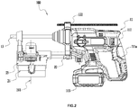
- a power tool 100 includes a tool main body 11, an auxiliary handle 12 and a dust collecting device 20.
- the auxiliary handle 12 can be considered as a part of the tool main body 11.
- the tool main body 11 may be a drill, a hammer, a screw driver, etc.
- an electric hammer is taken as an example.
- a tool attachment 13 can be mounted on the tool main body 11. In this example, the tool attachment 13 is a bit.
- the tool main body 11 includes a tool housing 111 and a first motor 112.
- the tool main body 11 further includes a battery pack 113 for supplying power to the first motor 112.
- the battery pack 113 is coupled detachably with the tool housing 111.
- the tool housing 111 is formed with a main handle 111a for a user to grip so as to operate the tool main body 11.
- the first motor 112 for outputting power to the tool attachment 13 is disposed within the tool housing 111.
- the tool main body 11 includes a transmission mechanism 114 and an output mechanism 115 disposed between the first motor 112 and the tool attachment 13.
- the transmission mechanism 114 and the output mechanism 115 are disposed within the tool housing 111.
- the transmission mechanism 114 is configured to transmit the power of the first motor 112 to the output mechanism 115.
- the output mechanism 115 includes an output shaft 115a for driving the tool attachment 13.
- a side of the tool main body 11 on which the tool attachment 13 is mounted is defined as a front of the tool
- the other side of the tool main body 11 on which the main handle 111a is formed is defined as a rear of the tool.
- the direction of a rotation axis of the output shaft 115a corresponds to the front and rear direction.
- the tool main body 11 is usually mounted with the auxiliary handle 12.
- the auxiliary handle 12 can be detached from the tool main body 11.
- the auxiliary handle 12 includes a handle portion 121 and a clamping portion 122.
- the handle portion 121 is used for the user to grip, and the clamping portion 122 is used to engage with the tool housing 111 so that the auxiliary handle 12 can clamp to the tool housing 111 detachably.
- the tool main body 11 generates dust during operation, especially for the electric hammer.
- the electric hammer generates a lot of dust during drilling process.
- the dust collecting device 20 is needed to absorb the dust so as to prevent the dust from moving freely in the environment.
- the dust collecting device 20 includes a dust collecting assembly 21 and a connecting assembly 22.
- the dust collecting assembly 21 for absorbing the dust is connected slidably with the connecting assembly 22 in the front and rear direction. So, the dust collecting assembly 21 is able to change its position based on different states of the tool attachment 13 during operation. For example, for the electric hammer, when the bit is drilling holes, as the hole becomes deeper, the dust collecting assembly 21 is expected to move rearward and close to the tool main body 11 in the front and rear direction.
- the connecting assembly 22 includes a connecting element 221 for connecting the dust collecting device 20 with the tool main body 11 detachably. Further, the connecting assembly 22 is connected with the auxiliary handle 12 detachably, and the auxiliary handle 12 is connected with the tool main body 11 detachably. So, the tool main body 11, the auxiliary handle 12 and the dust collecting device 20 can be separated from each other or combined as a whole. And the application range and usage mode of the power tool 100 is improved.
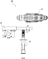
- the dust collecting assembly 21 includes a dust collecting housing 23, a fan 211, a second motor 212 and a battery 213.
- the fan 211, a second motor 212 and a battery 213 are disposed within the dust collecting housing 23.
- the fan 211 can be driven by the second motor 212 to rotate so as to generate an absorbing force.
- the second motor 212 is an electric motor specifically.
- the battery 213 is used to supply power to the second motor 212.
- the second motor 212 includes a stator and a rotor. The rotor is able to rotate relative to the stator about a first axis 101 which is substantially perpendicular to the front and rear direction.
- the first axis 101 can be considered as a rotation axis of the second motor 212. So, the second motor 212 is disposed within the dust collecting housing 23 in the direction of the first axis 101. On the one hand this arrangement can reduce the volume and weight of the tool main body 11, and on the other hand this arrangement can make the dust collecting assembly 21 have a reasonable construction so as to reduce the volume of the dust collecting device 20, which is beneficial to realize miniaturization of the dust collecting device 20.
- the battery 213 can be a rechargeable battery.
- the dust collecting housing 23 can be formed with a charging interface 213a allowing the battery 213 to be charged.
- the dust collecting housing 23 is connected slidably with the connecting assembly 22 in the front and rear direction. More specifically, the connecting assembly 22 includes a guiding rod 222 for guiding the dust collecting housing 23 to slide relative to the tool main body 11 in the front and rear direction.
- the dust collecting housing 23 is formed with a sliding hole 232a. An end of the guiding rod 222 which is closest to the dust collecting housing 23 is extended into the sliding hole 232a.
- a spring 214 is disposed within the sliding hole 232a, which rests against the guiding rod 222 and the dust collecting housing 23.
- the dust collecting housing 23 is rested against a working surface, and with the working process moves forward, the dust collecting housing 23 is able to move backward close to the tool main body 11 relative to the tool main body 11 in the front and rear direction under the guidance of the guiding rod 222.
- the object of absorbing dust effectively is reached.
- the dust collecting housing 23 further includes a dust collecting hood 231 which is formed with a hole 231a.
- the hole 231a allows the tool attachment 13 to pass there through.
- the dust collecting hood 231 is further formed with a dust collecting opening 231b close to the hole 231a. So, when the tool attachment 13 is driven by the tool main body 11 to operate, the dust generated can be absorbed into the dust collecting housing 23 through the dust collecting opening 231b.
- the second motor 212 is disposed between the first motor 112 and the dust collecting opening 231b. Thus, the size of the whole power tool 100 is further reduced.
- the dust collecting housing 23 is formed with a first containing chamber 232b, a second containing chamber 233a, a third containing chamber 234a and a forth containing chamber 232c.
- the first containing chamber 232b is used to contain the fan 211.
- the second containing chamber 233a is used to contain the dust absorbed by the dust collecting device 20.
- the third containing chamber 234a is used to contain the second motor 212.
- the forth containing chamber 232c is used to contain the battery 213.
- the first containing chamber 232b, the second containing chamber 233a, the third containing chamber 234a and the forth containing chamber 232c can be communicated with each other or isolated from each other.
- each part of the dust collecting housing 23 being formed with the first containing chamber 232b, the second containing chamber 233a, the third containing chamber 234a and the forth containing chamber 232c respectively can be formed separately and then connected as a whole or integrated directly.
- the second containing chamber 233a and the third containing chamber 234a are disposed on the two sides of the fan 211 respectively.
- the dust collecting opening 231b is communicated with the second containing chamber 233a, and the second containing chamber 233a is communicated with the first containing chamber 232b.
- the third containing chamber 234a is not communicated with the first containing chamber 232b and the forth containing chamber 232c is not communicated with the first containing chamber 232b.
- the dust collecting housing 23 includes a main housing 232, a dust box 233 and a motor housing 234.
- the main housing 232 is mounted slidably on an end of the guiding rod 222 which is far from the tool main body 11. So, the main housing 232 can be formed with the sliding hole 232a allowing the guiding rod 222 to extend there into.
- the main housing 232 also can be formed with the first containing chamber 232b for containing the fan 211 and the forth containing chamber 232c for containing the battery 213.
- the dust collecting hood 231 is disposed detachably on the main housing 232. So, the user can change to a different dust collecting hood 231 according to a different tool attachment 13.
- the dust box 233 is coupled detachably with the main housing 232 so as to form the second containing chamber 233a.
- a filter box 215 is disposed within the dust box 233, which is mounted detachably on the second containing chamber 233a. So, when the dust in the dust box 233 is too much, the user can detach the dust box 233 from the main housing 232 and dump the dust. When the filter box 215 is used for a long time, the user can change it or change the filter paper in the filter box 215.
- the dust collecting device 20 includes a safety switch 216 which can be activated by the filter box 215 when the filter box 215 is mounted on the dust box 233. The safety switch 216 can be turned on/off by the filter box 215.
- the second motor 212 When the user does not set the filter box 215 in the dust box 233, the second motor 212 is not allowed to be activated by the safety switch 216. While when the filter box 215 is mounted in the dust box 233, the safety switch 216 allows the second motor 212 to be activated by the user.
- the motor housing 234 is configured to form the third containing chamber 234a for containing the second motor 212.
- the motor housing 234 is mounted on the main housing 232.
- the motor housing 234 can be fixed on the main housing 232 through screws or fasteners.
- the second motor 212 is disposed in the motor housing 234 along the first axis 101 which is substantially perpendicular to the front and rear direction. Further, the second motor 212 and the dust box 233 are disposed on the two sides of the fan 211 respectively in the direction of the first axis 101. So, the construction of the whole dust collecting assembly 21 is further compact, and the volume is further reduced.
- the connecting assembly 22 includes a knob 223.
- the connecting assembly 22 is connected with the guiding rod 222 on its one end and connected rotatably with the clamping portion 122 of the auxiliary handle 12 on the other end through the knob 223.
- the auxiliary handle 12 can be rotated relative to the connecting element 221 about a second axis 102.
- the second axis 102 is substantially perpendicular to the front and rear direction and perpendicular to the length direction of the handle portion 121 of the auxiliary handle 12.
- the knob 223 is loosened first, and then the auxiliary handle 12 is rotated to make the auxiliary handle 12 rotate to the positions in FIGS. 8 and 9 respectively.
- the two positions in FIGS. 8 and 9 are suitable for the left-handed and right-handed users. So, it is convenient for the user to operate and use.
- the connecting element 221 includes a connecting portion 221a for connecting detachably with the guiding rod 222.
- the connecting portion 221a allows the connecting element 221 to connect with the guiding rod 222 at different positions along a longitudinal direction. So, when the user mounts the dust collecting device 20, he can adjust the extending length of the guiding rod 222 relative to the connecting element 221 in the front and rear direction in advance, so as to allow for use of the device 20 with tool attachments 13 having different lengths.
- the dust collecting device 20 further includes a main switch 217 allowing the dust collecting device 20 to be in an automatic mode.
- a main switch 217 allowing the dust collecting device 20 to be in an automatic mode.
- the dust collecting device 20 rests against the working surface and the dust collecting housing 23 slides a certain distance relative to the tool main body 11 in the front and rear direction, the second motor 212 is started to absorb dust. While when the dust collecting housing 23 restores to its original position, the second motor 212 is stopped.
- a trigger switch 218 is disposed on the dust collecting housing 23 and close to the sliding hole 232a.
- the trigger switch 218 is triggered so as to start the second motor 212. While when the dust collecting housing 23 slides on the guiding rod 222 to make the guiding rod 222 disengage with the trigger switch 218, the second motor 212 is stopped.
- a circuit board 219 is disposed in the dust collecting housing 23.
- a time-delay circuit for controlling the second motor 212 to delay stopping is disposed on the circuit board 219. So, when the user turns off the main switch 217, the time-delay circuit controls the second motor 212 to operate continuously for a preset time. Thus, the dust in the dust collecting channel can be absorbed thoroughly.
Landscapes
- Engineering & Computer Science (AREA)
- Mechanical Engineering (AREA)
- Percussive Tools And Related Accessories (AREA)
- Auxiliary Devices For Machine Tools (AREA)
Claims (7)
- Elektrowerkzeug (100), umfassend:einen Werkzeug-Hauptkörper (11), der einen ersten Motor (112) zur Ausgabe von Energie an ein Werkzeugzusatzgerät (13) umfasst; undeine Staubsammelvorrichtung (20), umfassend:einen Lüfter (211);einen zweiten Motor (212) zum Antreiben des Lüfters (211) zum Rotieren, um so eine absorbierende Kraft zu erzeugen;eine Verbindungsanordnung (22) zum lösbaren Verbinden der Staubsammelvorrichtung (20) mit dem Werkzeug-Hauptkörper (11); undein Staubsammelgehäuse (23), das beweglich mit der Verbindungsanordnung (22) in einer vorderen und hinteren Richtung verbunden ist;wobei der zweite Motor (212) umfasst:einen Stator; undeinen Rotor; undwobei das Staubsammelgehäuse (23) gebildet ist mit:einer ersten Aufnahmekammer (232b) zum Aufnehmen des Lüfters (211); undeiner zweiten Aufnahmekammer (233a) zum Aufnehmen von Staub, der durch die Staubsammelvorrichtung (20) aufgefangen wurde;dadurch gekennzeichnet, dass:der Rotor in der Lage ist, relativ zum Stator um eine erste Achse (101) zu rotieren, die im Wesentlichen senkrecht zur vorderen und hinteren Richtung ist;der Werkzeug-Hauptkörper (11) eine Werkzeugaufnahme (111) umfasst, die einen Hauptgriff (111a) umfasst, damit ein Benutzer ihn zum Handhaben des Werkzeug-Hauptkörpers (11) ergreifen kann, und einen Hilfsgriff (12), der einen Klemmteil (122) zum Festklemmen an der Werkzeugaufnahme (111) umfasst;wobei der Hilfsgriff (12) lösbar mit dem Werkzeug-Hauptkörper (11) verbunden ist, und die Verbindungsanordnung (22) ist lösbar mit dem Hilfsgriff (12) verbunden.
- Elektrowerkzeug nach Anspruch 1, wobei das Staubsammelgehäuse (23) ferner mit einer Staubsammelöffnung (231b) gebildet ist, die mit der zweiten Aufnahmekammer (233a) verbunden ist, und der zweite Motor (212) ist zwischen dem ersten Motor (112) und der Staubsammelöffnung (231b) angeordnet.
- Elektrowerkzeug nach Anspruch 1, wobei das Staubsammelgehäuse (23) ferner mit einer dritten Aufnahmekammer (234a) zum Aufnehmen des zweiten Motors (212) gebildet ist, und die zweite Aufnahmekammer (233a) und die dritte Aufnahmekammer (234a) sind auf zwei Seiten des Lüfters (211) angeordnet.
- Elektrowerkzeug nach Anspruch 1, wobei das Staubsammelgehäuse (23) ein Hauptgehäuse (232) zum Bilden der ersten Aufnahmekammer (232b) und einen Staubkasten (233) umfasst, der lösbar mit dem Hauptgehäuse (232) verbunden ist, um die zweite Aufnahmekammer (233a) zu bilden.
- Elektrowerkzeug nach Anspruch 4, wobei der zweite Motor (212) und der Staubkasten (233) auf beiden Seiten des Lüfters (211) in einer Richtung der ersten Achse (101) angeordnet sind.
- Elektrowerkzeug nach Anspruch 4, wobei die Staubsammelvorrichtung (20) ferner eine Filterbox (215) umfasst, die lösbar in der zweiten Aufnahmekammer (233a) angeordnet ist, und einen Sicherheitsschalter (216), der in der Lage ist, den zweiten Motor (212) an der Aktivierung durch einen Benutzer zu hindern, wenn die Filterbox (215) nicht in die zweite Aufnahmekammer (233a) eingesetzt ist.
- Elektrowerkzeug nach Anspruch 1, wobei die Staubsammelvorrichtung (20) ferner eine Batterie (213) zur Zufuhr von Energie zum zweiten Motor (212) umfasst, und das Staubsammelgehäuse (23) ist mit einer vierten Aufnahmekammer (232c) zum Aufnehmen der Batterie (213) gebildet.
Applications Claiming Priority (1)
| Application Number | Priority Date | Filing Date | Title |
|---|---|---|---|
| CN201611061013.5A CN108098700A (zh) | 2016-11-25 | 2016-11-25 | 动力工具 |
Publications (3)
| Publication Number | Publication Date |
|---|---|
| EP3326742A2 EP3326742A2 (de) | 2018-05-30 |
| EP3326742A3 EP3326742A3 (de) | 2018-08-22 |
| EP3326742B1 true EP3326742B1 (de) | 2020-02-12 |
Family
ID=60473336
Family Applications (1)
| Application Number | Title | Priority Date | Filing Date |
|---|---|---|---|
| EP17203433.2A Active EP3326742B1 (de) | 2016-11-25 | 2017-11-24 | Elektrowerkzeug mit staubfangvorrichtung |
Country Status (3)
| Country | Link |
|---|---|
| US (1) | US10639758B2 (de) |
| EP (1) | EP3326742B1 (de) |
| CN (1) | CN108098700A (de) |
Families Citing this family (9)
| Publication number | Priority date | Publication date | Assignee | Title |
|---|---|---|---|---|
| US10512997B2 (en) * | 2017-01-16 | 2019-12-24 | Makita Corporation | Dust collector for electric power tool and electric power tool |
| JP6965179B2 (ja) * | 2018-02-16 | 2021-11-10 | 株式会社マキタ | 電動工具 |
| US11298788B2 (en) * | 2018-06-19 | 2022-04-12 | Makita Corporation | Electric power tool dust collection system |
| US11673217B2 (en) | 2018-11-19 | 2023-06-13 | Milwaukee Electric Tool Corporation | Dust collector including filter cleaning mechanism |
| US11419466B2 (en) | 2020-03-25 | 2022-08-23 | Milwaukee Electric Tool Corporation | Dust collector assembly |
| JP7468154B2 (ja) | 2020-05-29 | 2024-04-16 | 工機ホールディングス株式会社 | 作業機 |
| US11819968B2 (en) | 2021-01-19 | 2023-11-21 | Milwaukee Electric Tool Corporation | Rotary power tool |
| WO2022212887A1 (en) | 2021-04-01 | 2022-10-06 | Milwaukee Electric Tool Corporation | Integrated dust extractor and power tool |
| CN115570631A (zh) * | 2021-07-06 | 2023-01-06 | 南京泉峰科技有限公司 | 斜锯及电动工具 |
Family Cites Families (10)
| Publication number | Priority date | Publication date | Assignee | Title |
|---|---|---|---|---|
| DE10342507A1 (de) * | 2003-09-12 | 2005-04-14 | Hilti Ag | Absaugvorrichtung |
| EP1714733B1 (de) * | 2005-04-20 | 2007-11-14 | Metabowerke GmbH | Staubabsaugeinrichtung |
| JP5376392B2 (ja) * | 2008-02-14 | 2013-12-25 | 日立工機株式会社 | 電動工具 |
| US8967923B2 (en) * | 2012-01-13 | 2015-03-03 | Aeg Electric Tools Gmbh | Dust suction device for drilling machine |
| US9776296B2 (en) * | 2008-05-09 | 2017-10-03 | Milwaukee Electric Tool Corporation | Power tool dust collector |
| CN201669687U (zh) * | 2010-06-12 | 2010-12-15 | 胡海明 | 一种电钻真空集尘器 |
| CN104070504B (zh) * | 2013-03-30 | 2017-06-16 | 苏州宝时得电动工具有限公司 | 电锤吹尘器 |
| WO2015058496A1 (en) * | 2013-10-21 | 2015-04-30 | Techtronic Power Tools Technology Limited | An accessory for an electric power tool |
| CN203804935U (zh) * | 2013-12-27 | 2014-09-03 | 利达机电有限公司 | 一种带有除尘装置的冲钻工具 |
| JP6208061B2 (ja) * | 2014-03-25 | 2017-10-04 | 株式会社マキタ | 作業工具 |
-
2016
- 2016-11-25 CN CN201611061013.5A patent/CN108098700A/zh active Pending
-
2017
- 2017-11-22 US US15/820,533 patent/US10639758B2/en active Active
- 2017-11-24 EP EP17203433.2A patent/EP3326742B1/de active Active
Non-Patent Citations (1)
| Title |
|---|
| None * |
Also Published As
| Publication number | Publication date |
|---|---|
| US20180147681A1 (en) | 2018-05-31 |
| US10639758B2 (en) | 2020-05-05 |
| EP3326742A3 (de) | 2018-08-22 |
| EP3326742A2 (de) | 2018-05-30 |
| CN108098700A (zh) | 2018-06-01 |
Similar Documents
| Publication | Publication Date | Title |
|---|---|---|
| EP3326742B1 (de) | Elektrowerkzeug mit staubfangvorrichtung | |
| US11712771B2 (en) | Power tool dust collector | |
| US10220457B2 (en) | Cutting device | |
| EP2012979A1 (de) | Griffanordnung für kraftbetriebenes werkzeug | |
| CN108380965B (zh) | 电动工具 | |
| CA2954154A1 (en) | Power tool with detachable auxiliary handle | |
| EP4070901A1 (de) | Schneidwerkzeug | |
| EP2127830B1 (de) | Hobel | |
| US11491597B2 (en) | Dust extraction device | |
| JP6258063B2 (ja) | 集塵装置 | |
| CN101468403B (zh) | 电动刳刨工具 | |
| JP5463907B2 (ja) | 電動工具 | |
| CN109848926B (zh) | 电动工具 | |
| JP2016087724A (ja) | コードレス電動作業機 | |
| JP5135869B2 (ja) | 集塵装置およびその集塵装置が設けられる電動工具 | |
| JP7455661B2 (ja) | 携帯用加工機 | |
| EP2990163B1 (de) | Elektrowerkzeug | |
| CN217453808U (zh) | 电动工具 | |
| JP2017221986A (ja) | 集塵装置および作業工具 | |
| JP7098432B2 (ja) | 吸塵ビット用集塵システム及びハンマードリル | |
| CN110962079A (zh) | 手持式工具 | |
| WO2022001744A1 (zh) | 电动工具 | |
| US20230415327A1 (en) | Integrated dust extractor and power tool | |
| US20240100641A1 (en) | Power tool dust collector | |
| JP7465647B2 (ja) | ハンマドリル |
Legal Events
| Date | Code | Title | Description |
|---|---|---|---|
| PUAI | Public reference made under article 153(3) epc to a published international application that has entered the european phase |
Free format text: ORIGINAL CODE: 0009012 |
|
| STAA | Information on the status of an ep patent application or granted ep patent |
Free format text: STATUS: THE APPLICATION HAS BEEN PUBLISHED |
|
| AK | Designated contracting states |
Kind code of ref document: A2 Designated state(s): AL AT BE BG CH CY CZ DE DK EE ES FI FR GB GR HR HU IE IS IT LI LT LU LV MC MK MT NL NO PL PT RO RS SE SI SK SM TR |
|
| AX | Request for extension of the european patent |
Extension state: BA ME |
|
| PUAL | Search report despatched |
Free format text: ORIGINAL CODE: 0009013 |
|
| AK | Designated contracting states |
Kind code of ref document: A3 Designated state(s): AL AT BE BG CH CY CZ DE DK EE ES FI FR GB GR HR HU IE IS IT LI LT LU LV MC MK MT NL NO PL PT RO RS SE SI SK SM TR |
|
| AX | Request for extension of the european patent |
Extension state: BA ME |
|
| RIC1 | Information provided on ipc code assigned before grant |
Ipc: B23Q 11/00 20060101ALI20180719BHEP Ipc: B25F 5/02 20060101ALI20180719BHEP Ipc: B23B 47/34 20060101AFI20180719BHEP Ipc: B28D 7/02 20060101ALI20180719BHEP |
|
| STAA | Information on the status of an ep patent application or granted ep patent |
Free format text: STATUS: REQUEST FOR EXAMINATION WAS MADE |
|
| 17P | Request for examination filed |
Effective date: 20190128 |
|
| RBV | Designated contracting states (corrected) |
Designated state(s): AL AT BE BG CH CY CZ DE DK EE ES FI FR GB GR HR HU IE IS IT LI LT LU LV MC MK MT NL NO PL PT RO RS SE SI SK SM TR |
|
| GRAP | Despatch of communication of intention to grant a patent |
Free format text: ORIGINAL CODE: EPIDOSNIGR1 |
|
| STAA | Information on the status of an ep patent application or granted ep patent |
Free format text: STATUS: GRANT OF PATENT IS INTENDED |
|
| INTG | Intention to grant announced |
Effective date: 20191023 |
|
| GRAS | Grant fee paid |
Free format text: ORIGINAL CODE: EPIDOSNIGR3 |
|
| GRAA | (expected) grant |
Free format text: ORIGINAL CODE: 0009210 |
|
| STAA | Information on the status of an ep patent application or granted ep patent |
Free format text: STATUS: THE PATENT HAS BEEN GRANTED |
|
| AK | Designated contracting states |
Kind code of ref document: B1 Designated state(s): AL AT BE BG CH CY CZ DE DK EE ES FI FR GB GR HR HU IE IS IT LI LT LU LV MC MK MT NL NO PL PT RO RS SE SI SK SM TR |
|
| REG | Reference to a national code |
Ref country code: GB Ref legal event code: FG4D |
|
| REG | Reference to a national code |
Ref country code: CH Ref legal event code: EP |
|
| REG | Reference to a national code |
Ref country code: AT Ref legal event code: REF Ref document number: 1231437 Country of ref document: AT Kind code of ref document: T Effective date: 20200215 |
|
| REG | Reference to a national code |
Ref country code: IE Ref legal event code: FG4D |
|
| REG | Reference to a national code |
Ref country code: DE Ref legal event code: R096 Ref document number: 602017011577 Country of ref document: DE |
|
| PG25 | Lapsed in a contracting state [announced via postgrant information from national office to epo] |
Ref country code: NO Free format text: LAPSE BECAUSE OF FAILURE TO SUBMIT A TRANSLATION OF THE DESCRIPTION OR TO PAY THE FEE WITHIN THE PRESCRIBED TIME-LIMIT Effective date: 20200512 Ref country code: FI Free format text: LAPSE BECAUSE OF FAILURE TO SUBMIT A TRANSLATION OF THE DESCRIPTION OR TO PAY THE FEE WITHIN THE PRESCRIBED TIME-LIMIT Effective date: 20200212 Ref country code: RS Free format text: LAPSE BECAUSE OF FAILURE TO SUBMIT A TRANSLATION OF THE DESCRIPTION OR TO PAY THE FEE WITHIN THE PRESCRIBED TIME-LIMIT Effective date: 20200212 |
|
| REG | Reference to a national code |
Ref country code: LT Ref legal event code: MG4D |
|
| REG | Reference to a national code |
Ref country code: NL Ref legal event code: MP Effective date: 20200212 |
|
| PG25 | Lapsed in a contracting state [announced via postgrant information from national office to epo] |
Ref country code: HR Free format text: LAPSE BECAUSE OF FAILURE TO SUBMIT A TRANSLATION OF THE DESCRIPTION OR TO PAY THE FEE WITHIN THE PRESCRIBED TIME-LIMIT Effective date: 20200212 Ref country code: SE Free format text: LAPSE BECAUSE OF FAILURE TO SUBMIT A TRANSLATION OF THE DESCRIPTION OR TO PAY THE FEE WITHIN THE PRESCRIBED TIME-LIMIT Effective date: 20200212 Ref country code: LV Free format text: LAPSE BECAUSE OF FAILURE TO SUBMIT A TRANSLATION OF THE DESCRIPTION OR TO PAY THE FEE WITHIN THE PRESCRIBED TIME-LIMIT Effective date: 20200212 Ref country code: BG Free format text: LAPSE BECAUSE OF FAILURE TO SUBMIT A TRANSLATION OF THE DESCRIPTION OR TO PAY THE FEE WITHIN THE PRESCRIBED TIME-LIMIT Effective date: 20200512 Ref country code: IS Free format text: LAPSE BECAUSE OF FAILURE TO SUBMIT A TRANSLATION OF THE DESCRIPTION OR TO PAY THE FEE WITHIN THE PRESCRIBED TIME-LIMIT Effective date: 20200612 Ref country code: GR Free format text: LAPSE BECAUSE OF FAILURE TO SUBMIT A TRANSLATION OF THE DESCRIPTION OR TO PAY THE FEE WITHIN THE PRESCRIBED TIME-LIMIT Effective date: 20200513 |
|
| PG25 | Lapsed in a contracting state [announced via postgrant information from national office to epo] |
Ref country code: NL Free format text: LAPSE BECAUSE OF FAILURE TO SUBMIT A TRANSLATION OF THE DESCRIPTION OR TO PAY THE FEE WITHIN THE PRESCRIBED TIME-LIMIT Effective date: 20200212 |
|
| PG25 | Lapsed in a contracting state [announced via postgrant information from national office to epo] |
Ref country code: SK Free format text: LAPSE BECAUSE OF FAILURE TO SUBMIT A TRANSLATION OF THE DESCRIPTION OR TO PAY THE FEE WITHIN THE PRESCRIBED TIME-LIMIT Effective date: 20200212 Ref country code: DK Free format text: LAPSE BECAUSE OF FAILURE TO SUBMIT A TRANSLATION OF THE DESCRIPTION OR TO PAY THE FEE WITHIN THE PRESCRIBED TIME-LIMIT Effective date: 20200212 Ref country code: PT Free format text: LAPSE BECAUSE OF FAILURE TO SUBMIT A TRANSLATION OF THE DESCRIPTION OR TO PAY THE FEE WITHIN THE PRESCRIBED TIME-LIMIT Effective date: 20200705 Ref country code: SM Free format text: LAPSE BECAUSE OF FAILURE TO SUBMIT A TRANSLATION OF THE DESCRIPTION OR TO PAY THE FEE WITHIN THE PRESCRIBED TIME-LIMIT Effective date: 20200212 Ref country code: EE Free format text: LAPSE BECAUSE OF FAILURE TO SUBMIT A TRANSLATION OF THE DESCRIPTION OR TO PAY THE FEE WITHIN THE PRESCRIBED TIME-LIMIT Effective date: 20200212 Ref country code: ES Free format text: LAPSE BECAUSE OF FAILURE TO SUBMIT A TRANSLATION OF THE DESCRIPTION OR TO PAY THE FEE WITHIN THE PRESCRIBED TIME-LIMIT Effective date: 20200212 Ref country code: LT Free format text: LAPSE BECAUSE OF FAILURE TO SUBMIT A TRANSLATION OF THE DESCRIPTION OR TO PAY THE FEE WITHIN THE PRESCRIBED TIME-LIMIT Effective date: 20200212 Ref country code: RO Free format text: LAPSE BECAUSE OF FAILURE TO SUBMIT A TRANSLATION OF THE DESCRIPTION OR TO PAY THE FEE WITHIN THE PRESCRIBED TIME-LIMIT Effective date: 20200212 Ref country code: CZ Free format text: LAPSE BECAUSE OF FAILURE TO SUBMIT A TRANSLATION OF THE DESCRIPTION OR TO PAY THE FEE WITHIN THE PRESCRIBED TIME-LIMIT Effective date: 20200212 |
|
| REG | Reference to a national code |
Ref country code: DE Ref legal event code: R097 Ref document number: 602017011577 Country of ref document: DE |
|
| REG | Reference to a national code |
Ref country code: AT Ref legal event code: MK05 Ref document number: 1231437 Country of ref document: AT Kind code of ref document: T Effective date: 20200212 |
|
| PLBE | No opposition filed within time limit |
Free format text: ORIGINAL CODE: 0009261 |
|
| STAA | Information on the status of an ep patent application or granted ep patent |
Free format text: STATUS: NO OPPOSITION FILED WITHIN TIME LIMIT |
|
| 26N | No opposition filed |
Effective date: 20201113 |
|
| PG25 | Lapsed in a contracting state [announced via postgrant information from national office to epo] |
Ref country code: AT Free format text: LAPSE BECAUSE OF FAILURE TO SUBMIT A TRANSLATION OF THE DESCRIPTION OR TO PAY THE FEE WITHIN THE PRESCRIBED TIME-LIMIT Effective date: 20200212 Ref country code: IT Free format text: LAPSE BECAUSE OF FAILURE TO SUBMIT A TRANSLATION OF THE DESCRIPTION OR TO PAY THE FEE WITHIN THE PRESCRIBED TIME-LIMIT Effective date: 20200212 |
|
| PG25 | Lapsed in a contracting state [announced via postgrant information from national office to epo] |
Ref country code: SI Free format text: LAPSE BECAUSE OF FAILURE TO SUBMIT A TRANSLATION OF THE DESCRIPTION OR TO PAY THE FEE WITHIN THE PRESCRIBED TIME-LIMIT Effective date: 20200212 Ref country code: PL Free format text: LAPSE BECAUSE OF FAILURE TO SUBMIT A TRANSLATION OF THE DESCRIPTION OR TO PAY THE FEE WITHIN THE PRESCRIBED TIME-LIMIT Effective date: 20200212 |
|
| PG25 | Lapsed in a contracting state [announced via postgrant information from national office to epo] |
Ref country code: MC Free format text: LAPSE BECAUSE OF FAILURE TO SUBMIT A TRANSLATION OF THE DESCRIPTION OR TO PAY THE FEE WITHIN THE PRESCRIBED TIME-LIMIT Effective date: 20200212 |
|
| REG | Reference to a national code |
Ref country code: CH Ref legal event code: PL |
|
| PG25 | Lapsed in a contracting state [announced via postgrant information from national office to epo] |
Ref country code: LU Free format text: LAPSE BECAUSE OF NON-PAYMENT OF DUE FEES Effective date: 20201124 |
|
| REG | Reference to a national code |
Ref country code: BE Ref legal event code: MM Effective date: 20201130 |
|
| PG25 | Lapsed in a contracting state [announced via postgrant information from national office to epo] |
Ref country code: LI Free format text: LAPSE BECAUSE OF NON-PAYMENT OF DUE FEES Effective date: 20201130 Ref country code: CH Free format text: LAPSE BECAUSE OF NON-PAYMENT OF DUE FEES Effective date: 20201130 |
|
| PG25 | Lapsed in a contracting state [announced via postgrant information from national office to epo] |
Ref country code: FR Free format text: LAPSE BECAUSE OF NON-PAYMENT OF DUE FEES Effective date: 20201130 Ref country code: IE Free format text: LAPSE BECAUSE OF NON-PAYMENT OF DUE FEES Effective date: 20201124 |
|
| PG25 | Lapsed in a contracting state [announced via postgrant information from national office to epo] |
Ref country code: TR Free format text: LAPSE BECAUSE OF FAILURE TO SUBMIT A TRANSLATION OF THE DESCRIPTION OR TO PAY THE FEE WITHIN THE PRESCRIBED TIME-LIMIT Effective date: 20200212 Ref country code: MT Free format text: LAPSE BECAUSE OF FAILURE TO SUBMIT A TRANSLATION OF THE DESCRIPTION OR TO PAY THE FEE WITHIN THE PRESCRIBED TIME-LIMIT Effective date: 20200212 Ref country code: CY Free format text: LAPSE BECAUSE OF FAILURE TO SUBMIT A TRANSLATION OF THE DESCRIPTION OR TO PAY THE FEE WITHIN THE PRESCRIBED TIME-LIMIT Effective date: 20200212 |
|
| PG25 | Lapsed in a contracting state [announced via postgrant information from national office to epo] |
Ref country code: MK Free format text: LAPSE BECAUSE OF FAILURE TO SUBMIT A TRANSLATION OF THE DESCRIPTION OR TO PAY THE FEE WITHIN THE PRESCRIBED TIME-LIMIT Effective date: 20200212 Ref country code: AL Free format text: LAPSE BECAUSE OF FAILURE TO SUBMIT A TRANSLATION OF THE DESCRIPTION OR TO PAY THE FEE WITHIN THE PRESCRIBED TIME-LIMIT Effective date: 20200212 |
|
| PG25 | Lapsed in a contracting state [announced via postgrant information from national office to epo] |
Ref country code: BE Free format text: LAPSE BECAUSE OF NON-PAYMENT OF DUE FEES Effective date: 20201130 |
|
| PGFP | Annual fee paid to national office [announced via postgrant information from national office to epo] |
Ref country code: GB Payment date: 20221103 Year of fee payment: 6 Ref country code: DE Payment date: 20220621 Year of fee payment: 6 |
|
| REG | Reference to a national code |
Ref country code: DE Ref legal event code: R082 Ref document number: 602017011577 Country of ref document: DE Representative=s name: SUN, YIMING, M.SC. DIPL. SC. POL. UNIV., DE |