EP3325960B1 - Vorrichtung zur untersuchung eines körpergewebes durch akustische spektroskopie - Google Patents
Vorrichtung zur untersuchung eines körpergewebes durch akustische spektroskopie Download PDFInfo
- Publication number
- EP3325960B1 EP3325960B1 EP16734578.4A EP16734578A EP3325960B1 EP 3325960 B1 EP3325960 B1 EP 3325960B1 EP 16734578 A EP16734578 A EP 16734578A EP 3325960 B1 EP3325960 B1 EP 3325960B1
- Authority
- EP
- European Patent Office
- Prior art keywords
- signal
- ultrasonic
- results
- values
- time
- Prior art date
- Legal status (The legal status is an assumption and is not a legal conclusion. Google has not performed a legal analysis and makes no representation as to the accuracy of the status listed.)
- Active
Links
Images


Classifications
-
- G—PHYSICS
- G01—MEASURING; TESTING
- G01N—INVESTIGATING OR ANALYSING MATERIALS BY DETERMINING THEIR CHEMICAL OR PHYSICAL PROPERTIES
- G01N29/00—Investigating or analysing materials by the use of ultrasonic, sonic or infrasonic waves; Visualisation of the interior of objects by transmitting ultrasonic or sonic waves through the object
- G01N29/44—Processing the detected response signal, e.g. electronic circuits specially adapted therefor
- G01N29/46—Processing the detected response signal, e.g. electronic circuits specially adapted therefor by spectral analysis, e.g. Fourier analysis or wavelet analysis
-
- A—HUMAN NECESSITIES
- A61—MEDICAL OR VETERINARY SCIENCE; HYGIENE
- A61B—DIAGNOSIS; SURGERY; IDENTIFICATION
- A61B8/00—Diagnosis using ultrasonic, sonic or infrasonic waves
- A61B8/08—Clinical applications
- A61B8/0808—Clinical applications for diagnosis of the brain
-
- A—HUMAN NECESSITIES
- A61—MEDICAL OR VETERINARY SCIENCE; HYGIENE
- A61B—DIAGNOSIS; SURGERY; IDENTIFICATION
- A61B8/00—Diagnosis using ultrasonic, sonic or infrasonic waves
- A61B8/42—Details of probe positioning or probe attachment to the patient
- A61B8/4272—Details of probe positioning or probe attachment to the patient involving the acoustic interface between the transducer and the tissue
- A61B8/4281—Details of probe positioning or probe attachment to the patient involving the acoustic interface between the transducer and the tissue characterised by sound-transmitting media or devices for coupling the transducer to the tissue
-
- A—HUMAN NECESSITIES
- A61—MEDICAL OR VETERINARY SCIENCE; HYGIENE
- A61B—DIAGNOSIS; SURGERY; IDENTIFICATION
- A61B8/00—Diagnosis using ultrasonic, sonic or infrasonic waves
- A61B8/52—Devices using data or image processing specially adapted for diagnosis using ultrasonic, sonic or infrasonic waves
- A61B8/5207—Devices using data or image processing specially adapted for diagnosis using ultrasonic, sonic or infrasonic waves involving processing of raw data to produce diagnostic data, e.g. for generating an image
-
- G—PHYSICS
- G01—MEASURING; TESTING
- G01N—INVESTIGATING OR ANALYSING MATERIALS BY DETERMINING THEIR CHEMICAL OR PHYSICAL PROPERTIES
- G01N29/00—Investigating or analysing materials by the use of ultrasonic, sonic or infrasonic waves; Visualisation of the interior of objects by transmitting ultrasonic or sonic waves through the object
- G01N29/02—Analysing fluids
- G01N29/024—Analysing fluids by measuring propagation velocity or propagation time of acoustic waves
-
- G—PHYSICS
- G01—MEASURING; TESTING
- G01N—INVESTIGATING OR ANALYSING MATERIALS BY DETERMINING THEIR CHEMICAL OR PHYSICAL PROPERTIES
- G01N29/00—Investigating or analysing materials by the use of ultrasonic, sonic or infrasonic waves; Visualisation of the interior of objects by transmitting ultrasonic or sonic waves through the object
- G01N29/02—Analysing fluids
- G01N29/032—Analysing fluids by measuring attenuation of acoustic waves
-
- G—PHYSICS
- G01—MEASURING; TESTING
- G01N—INVESTIGATING OR ANALYSING MATERIALS BY DETERMINING THEIR CHEMICAL OR PHYSICAL PROPERTIES
- G01N29/00—Investigating or analysing materials by the use of ultrasonic, sonic or infrasonic waves; Visualisation of the interior of objects by transmitting ultrasonic or sonic waves through the object
- G01N29/04—Analysing solids
- G01N29/07—Analysing solids by measuring propagation velocity or propagation time of acoustic waves
-
- G—PHYSICS
- G01—MEASURING; TESTING
- G01N—INVESTIGATING OR ANALYSING MATERIALS BY DETERMINING THEIR CHEMICAL OR PHYSICAL PROPERTIES
- G01N29/00—Investigating or analysing materials by the use of ultrasonic, sonic or infrasonic waves; Visualisation of the interior of objects by transmitting ultrasonic or sonic waves through the object
- G01N29/04—Analysing solids
- G01N29/11—Analysing solids by measuring attenuation of acoustic waves
-
- G—PHYSICS
- G01—MEASURING; TESTING
- G01N—INVESTIGATING OR ANALYSING MATERIALS BY DETERMINING THEIR CHEMICAL OR PHYSICAL PROPERTIES
- G01N29/00—Investigating or analysing materials by the use of ultrasonic, sonic or infrasonic waves; Visualisation of the interior of objects by transmitting ultrasonic or sonic waves through the object
- G01N29/44—Processing the detected response signal, e.g. electronic circuits specially adapted therefor
- G01N29/4409—Processing the detected response signal, e.g. electronic circuits specially adapted therefor by comparison
- G01N29/4427—Processing the detected response signal, e.g. electronic circuits specially adapted therefor by comparison with stored values, e.g. threshold values
Definitions
- the invention relates to a device for examining body tissue by acoustic spectroscopy
- a method for determining the state of a mixture of substances by measuring the speed of sound and/or ultrasonic attenuation is disclosed DE 10 2008 014 300 A1 .
- the amplitudes of the transmitted and reflected sound waves are evaluated and the transit time of the individual sound waves is calculated from the squared signal amplitude of the transmitted and received signals.
- Ju Bing-Feng et al. propose in their publication entitled "Simultaneous measurement of longitudinal and transverse velocities, attenuation, density, and thickness of films by using point-focus ultrasonic spectroscopy" in the Journal of Applied Physics presents a further method for determining the acoustic and geometric properties of a thin-layer test material using spectroscopy, in which the acoustic impedance, the attenuation coefficient and the transit time of the focused ultrasonic waves can be calculated from the reflection spectra of the ultrasonic waves.
- a device for the continuous examination of a (biological) medium is from the DE 20 2007 017 911 U1 a device is known which generates a cone-shaped radiation characteristic in order to enable an assessment of the condition of the test material based on the comparison of a reference pattern of phase shifts with the phase shifts occurring at a receiver; It is also possible, in addition to the phase shift, to evaluate the amplitude change between the transmitted and received signal components of the same frequency.
- a further method and a device for characterizing a polymer melt are known, with which the time difference between two successive ultrasound echoes emerging from a polymer melt can be determined. To calculate the acoustic material characteristics, this method takes into account the amplitude changes that occur.
- a device for combining acoustic and electroacoustic spectroscopy is the US 6,109,098 A refer to. To characterize dispersed systems, it is proposed to determine both the particle size distribution and the zeta potential of the system.
- Spectroscopic devices record a large number of data, which are subsequently compressed and/or reduced to simplify and/or accelerate further processing.
- Methods for compressing and/or reducing automatically collected data are described in the publications DE 103 53 132 B3 , DE 41 41 123 C1 and DE 10 2005 005 386 B3 suggested.
- Another device for examining liquid or gaseous media by acoustic spectroscopy is, for example, from DE 103 24 990 B2 known.
- This device has a transmitting device for sending several transmission signals of different frequencies and a receiving device for receiving corresponding reception signals.
- a processing device can then be used to determine the phase shift for each pair of transmit and receive signals and to derive a value that qualifies the medium being examined based on the phase shift.
- signal packets of different frequencies are sent one after the other in direct succession.
- the frequencies are preferably in the range between 1 and 15 MHz, with each signal packet preferably comprising at least 100 periods. For each signal packet and thus for each frequency level, the specific received signals are recorded via the receiving device and then sent to a processing device.
- the phase shift angle between the two signals caused by the passage through the medium being examined is determined for each frequency-specific transmission and reception signal pair.
- this frequency-specific scanning of the medium records a large number of different frequency-specific phase shift values, the number of which depends on the number of transmit and receive signal pairs. In this way, information about the behavior of the medium is obtained from a very large frequency range defined across individual frequency levels, whereby this information enables statements to be made about the properties of the medium being examined.
- frequency-specific scanning of the medium and the corresponding determination of the frequency-related phase angles a much more specific examination of the medium can be achieved, since a change in the medium has different effects on the respective frequency-specific transmit and receive signal pair.
- the device described is that it is based on the evaluation of the phase shift values caused by the passage of the transmission signal through the one to be examined characteristic and is documented by the received signal.
- the evaluation of the phase shift between the transmitted signal and the received signal can lead to undesirable loss of information, which significantly distorts the evaluation result. This loss of information is due to the fact that the value of the phase shift is limited to a value range between 0 and 360°.
- the method described in the publication provides a phase shift value that cannot be clearly assigned.
- the evaluation device described in the publication delivers a phase shift value of 40°.
- the DE 198 41 154 A1 the generation of transmission signals with different frequencies.
- the different frequencies serve like a vernier when evaluating the phase shifts. This makes it possible to clearly assign the measured phase shift values to the actual phase shift between the transmitted signal and the received signal.
- this method has the disadvantage that the sound waves in the medium to be examined are transmitted at different speeds of sound depending on the respective transmission frequency, and these different transmission speeds can lead to significant measurement errors in the medium to be examined.
- the dependence of the propagation speed of the transmission signal on the respective transmission frequency is described by the Kramers-Kronig equation.
- the measurement method has been developed in accordance with DE 198 41 154 A1 as unsuitable proven, since the measurement errors cannot be taken into account due to the non-uniform propagation speed of the sound waves depending on the respective transmission frequency.
- the material to be examined is body tissue.
- body tissue especially, but by no means exclusively, for diagnostic purposes, there is often the problem that the body tissue cannot be easily removed for the examination, so that only non-invasive examination methods can be used. For example, if examinations are to be carried out on the human brain, removal of body tissue is in most cases not possible due to the obvious side effects of opening the human skull.
- the object of the present invention is to propose a device for the non-invasive examination of body tissue by acoustic spectroscopy, in which the sources of error described above are excluded.
- the device according to the invention for the non-invasive examination of a body tissue by acoustic spectroscopy comprises an ultrasound transmitting device for emitting ultrasound transmission signals and an ultrasound receiving device for receiving the reflected or transmitted ultrasound reception signals after passing through the body tissue to be examined. Both the transmitting device and the receiving device are suitable for sending or receiving ultrasonic signals of different frequencies fi to f n .
- the device comprises a first processing device, a second processing device, a signal switch provided between the ultrasound receiving device on the one hand and the two processing devices on the other hand, a storage device and an evaluation device.
- the frequency-dependent throughput time values of the assigned ultrasonic signal of each transmit and receive signal pair can be measured directly; with the second processing device, the frequency-dependent attenuation values of the assigned ultrasonic signal can be determined from each transmit and receive signal pair.
- an ultrasound reception signal received can be routed identically to both processing devices for parallel processing.
- the respectively determined throughput time values and attenuation values can be stored at least temporarily as a result data record; in the evaluation device, the result data record is a qualifying value can be derived to describe the examined body tissue.
- the phase shift for each transmit and receive signal pair is not determined during signal evaluation.
- the transit time of the associated ultrasonic signal is determined from each pair of transmit and receive signals in the first processing device.
- the attenuation of the associated ultrasound signal as it passes through the body tissue to be examined is determined from each pair of transmit and receive signals.
- the phase of the transmission signal since the phase of the transmission signal is not necessary for determining the transit time and attenuation of the transmission signal as it passes through the body tissue to be examined. So only the data describing the transmit signal and received signal that is necessary to determine the throughput time and attenuation need to be recorded.
- tissue changes in the human brain are accompanied by changes in the dispersive character of the brain tissue, which can be determined using the device according to the invention.
- a patient's risk of stroke as a result of tissue changes in the brain can be recorded and quantitatively estimated.
- Alzheimer's disease or Parkinson's disease also leads to tissue changes in the brain, which are accompanied by significant changes in the throughput time and attenuation when exposed to ultrasound signals and can be determined using the device according to the invention.
- the device according to the invention thus provides a device with which pathological changes in body tissue can be determined and quantitatively estimated using non-invasive acoustic spectroscopy.
- the manner in which the data reduction device reduces the result data sets is fundamentally arbitrary.
- the maximum and minimum throughput time as well as the maximum and minimum attenuation are determined in a result data set that contains all transmission frequencies and all transmission and reception signal pairs for the examination of a material. These two maximum and two minimum values then form a reduced result data set.
- This data reduction can be assumed to be characteristic of the original data set, since the rectangular data quadrant spanned by the two maximum values and the two minimum values includes all other result data.
- An even greater data reduction can be achieved if not only the result data of one result data set, but the result data of several result data sets are combined in the data reduction device. For example, if examinations were carried out on a large number of people, the result data from the result data sets of all male examination subjects and, on the other hand, the result data from the result data sets of all female examination subjects can be summarized. The reduced result data sets then represent the result data of the male examiners on the one hand and the female examiners on the other. In the same way, for example, the result data sets from different age groups can be combined. Which classes in the result data reduction are summarized in each case is basically arbitrary and only depends on the desired examination result.
- the data reduction device can be used to determine the maximum and minimum throughput time values and the maximum and minimum attenuation values in all of the result data sets represented by a class.
- the two maximum values or the two minimum values then span a result data space that includes and represents the result data from all combined result data sets.
- a further possibility for data reduction is to determine in the data reduction device at least a quantile of the throughput time values in a determined result data set and at least a quantile of the attenuation values in this result data set. These quantiles are then stored as a reduced results data set.
- a quantile should be understood as a statistical threshold value in the set of throughput time values or the set of attenuation values of one or more result data sets.
- the way in which the result data sets determined using the device according to the invention or the reduced result data sets derived therefrom are used is fundamentally arbitrary. It is particularly advantageous if the device can be used to carry out an evaluation that results in a value that qualifies the material, for example a body tissue.
- a value that qualifies the material for example a body tissue.
- the manner in which the qualifying value for describing the examined material is derived in the evaluation device from the result data sets or from the reduced result data sets is fundamentally arbitrary. It is particularly advantageous if this is done in the form of a pattern comparison, in which the result data sets are compared with comparison result data sets from a database.
- the comparison result data sets represent measurements on comparison materials with known properties. This can be body tissue from patients with known diseases, such as Alzheimer's, Parkinson's or high blood pressure. It is also conceivable that the comparison result data sets were representative of measurements taken on cell tissue with special markings in the cells.
- the throughput time can be determined with a resolution of at least 100 picoseconds in the first processing device.
- the throughput time should preferably be able to be determined with a resolution of at least 10 picoseconds.
- Which time measuring device is provided in the first processing device for determining the throughput time is basically arbitrary. In order to achieve resolutions when measuring the throughput time, especially in the range of less than 10 picoseconds, it is essential to the invention if a time-to-digital converter is used.
- Time-to-digital converters are electronic assemblies that can measure time intervals in the range of less than 100 picoseconds and convert them into a digital output. The time measurement is based on the known transit time of an electrical signal through the components of the TDC converter.
- the throughput time is then determined by how many of the electronic circuits with a known throughput time are passed through between the emission of the transmission signal on the one hand and the reception of the input signal on the other. This number of cycles of electronic assemblies with a known cycle time is then counted, with the measured cycle time then corresponding to multiplying the known cycle time of an individual circuit by the number of cycles.
- the device according to the invention contains a signal switch with which a respectively received ultrasound reception signal is passed identically for parallel processing to the first processing device for determining the throughput time and the second processing device for determining the attenuation.
- the device is suitable for the non-invasive examination of body tissue.
- the body tissue of a body part to be examined is exposed to the ultrasound transmission signals and the ultrasound reception signals recorded after passing through the body tissue.
- the device according to the invention offers particularly great advantages when examining the human brain, since examinations of the human brain, in particular molecular or cellular examinations, have otherwise not been able to be carried out at all or only with very little informative value. Since opening the human skull to examine the brain tissue is not possible in most cases due to the significant side effects, examinations of the brain tissue can currently only be carried out using imaging methods such as magnetic resonance therapy or computer tomography. However, these imaging procedures do not generally allow differentiated diagnostic statements about most diseases in the brain.
- the ultrasound transmitting device or the ultrasound receiving device should be suitable for temporary and/or permanent placement on the outside of the patient's scalp. This attachment of the ultrasound transmitting device or the ultrasound receiving device to the scalp usually does not require a doctor, but the transmitting and receiving device can also be carried out by appropriately trained nursing staff or even by laypeople.
- the type of ultrasound waves used for examination using the device according to the invention is basically arbitrary. Longitudinal ultrasound waves in the lower MHz range are particularly suitable.
- the ultrasonic transmission signals of different frequencies are sent out individually one after the other or as groups one after the other from the ultrasonic transmitting device.
- the ultrasound transmission signal for the different frequencies can also be modeled onto a common carrier signal and transmitted using the ultrasound transmission device. It is also possible for the ultrasound transmission signals of different frequencies in the ultrasound transmission device to be added to a common carrier signal as a superposition and sent out together.
- the transmission device generates transmission signals with different frequencies in order to determine a transmission and reception signal pair for each of these frequencies and to evaluate it to characterize the material being examined.
- it can also be useful to use the transmitting device to send out ultrasonic transmission signals with different amplitudes. This allows the data to be evaluated in an even more differentiated manner.
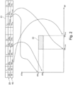
- Fig. 1 shows in a schematic sketch the basic structure of a device 01 according to the invention, as it can be used for the non-invasive examination of a material 02, for example a brain, for example a skull, by methods of acoustic spectroscopy.
- the device 01 comprises, on the one hand, an ultrasonic transmitting device 03 and an ultrasonic receiving device 04.
- the device 01 further comprises a signal preparation module 05, a signal generator 06 and a signal amplifier 07 for generating the ultrasonic signals to be emitted at the ultrasonic transmitting device 03.
- the ultrasound signals After passing through the body tissue 02 directly or indirectly (reflection), the ultrasound signals are collected at the ultrasound receiving device 04 and amplified by means of a signal amplifier 08.
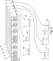
- the amplified received signals are then divided in a signal switch 09 and distributed to a first processing device 10 and a second processing device 11 for parallel processing.
- the first processing device 10 is used to determine the transit times that the ultrasound signal requires to pass through the body tissue 02 at the respective set frequency.
- the received signal After passing through a signal processing module 12, the received signal reaches a time-to-digital converter 13, with which the transit time of the ultrasonic signal, i.e. the time between the emission at the ultrasonic transmitting device 03 and the reception of the ultrasonic signal at the ultrasonic receiving device 04, can be measured.
- the function of the time-to-digital converter 13 is based on the fact that the transit time of an electrical signal is known through a large number of electronic circuits 14 contained in the time-to-digital converter 13.
- the trigger signal of the ultrasonic transmission signal is also sent to the time-to-digital converter 13 at the same time as the emission at the ultrasonic transmission device 03 in order to start the time measurement process.
- the trigger signal of the ultrasonic transmission signal then passes through the circuits 14 arranged one behind the other in the time-to-digital converter 13.
- Each cycle of an electronic circuit 14, which corresponds to a predetermined cycle time, is added up by a counter 15.
- the counter 15 switches off and multiplies the number of added cycles by the known cycle time of the individual electronic circuits 14. This then results in the total cycle time 16 for a pair of transmit and receive signals. For each transmission frequency results there is a throughput time 16, which is stored in a memory device 17 associated with the respective transmission frequency.
- the signal attenuation of the ultrasound transmission signal as it passes through the body tissue 02 is determined in the second processing device 11.
- a signal processing module 18 is provided in the second processing device 11, with which the signal is processed and the amplitude of the ultrasonic received signal is determined.
- the amplitude of the ultrasound reception signal is then compared with the amplitude of the ultrasound transmission signal in an evaluation module 19.
- the associated attenuation 20 can be determined in the second processing device 11 for each frequency of a transmit and receive signal pair and stored in the memory device 17.
- predefined signal curves with different transmission frequencies are defined by a controller 42 and then emitted by the ultrasound transmitter 03.
- the throughput time 16 and the attenuation value 20 are determined by evaluating the transmission and reception signal pair generated therefrom and stored in the memory device 17.
- a result data record 21 is stored in the storage device 17.
- the result data set 21 contains the associated throughput time 16 and the associated attenuation value 20 for each of the frequencies f l to f n , so that the result data set 21 represents a fingerprint of the material properties of the body tissue 02 determined by acoustic spectroscopy.
- the storage device 17 is followed by a data reduction device 22, the functionality of which is explained below using the schematic diagram in Fig. 2 should be explained.
- Fig. 2 represents an example of a result data set 21 in which the associated throughput times (ToF) and the associated attenuation values (ATN) are stored for each transmission frequency fi to f n .
- the result data set 21 can certainly contain a very large number of data if, for example, the respective throughput time and attenuation were determined on a body tissue 02 for several hundred frequencies.
- data reduction can be carried out in the data reduction device 22 as follows. The maximum and minimum values are determined from the throughput time values 16 stored in the result data set 21 and the stored attenuation values 20. Im in Fig.
- the damping value ATN 3 represents the minimum damping value and the damping value ATN n-2 represents the maximum damping value. Furthermore, the throughput time value ToF 2 represents the throughput time maximum and the throughput time value ToF nl represents the throughput time minimum.
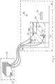
- Fig. 1 the data reduction device 22 is followed by an evaluation device 25, which interacts with a database 26 in the evaluation of the reduced result data sets 23.
- a large number of comparison result data sets 27 are stored in the database 26, which were determined by measuring comparison body parts with known properties.
- the operation of the evaluation device 25 in cooperation with the database 26 should below based on the schematic sketches in Fig. 3 and Fig. 4 be explained in more detail.
- Fig. 3 first shows the database 26 with the various comparison result data sets 27.
- Each comparison result data set 27 was determined by an acoustic spectroscopy examination on a comparison body part with known properties.
- a pattern comparison of the reduced result data set 23, which represents the body tissue 02, is then carried out in the evaluation device 25 with the reduced comparison result data sets 28 to 30.
- the reduced result data set 23 of the body tissue 02 shows the greatest matches with the reduced comparison result data set 29.
- the body tissue 02 can be qualified in the evaluation device 25 as being comparable in its properties to the properties of the comparison body part, which is represented by the reduced result data set 29 become. In other words, this means that after the pattern comparison has been carried out, it can be displayed on the evaluation device 25 that the body tissue 02 significantly matches the body tissue represented by the reduced comparison result data set 29.
- Fig. 4 serves to explain a further variant for data reduction in the device according to the invention. This should be done, for example, using the data reduction of the data in the database 26 with the comparison data sets 27. As already explained above, each result data set 27 of the database 26 can be mapped onto a reduced result data set, which is represented as a rectangle in the coordinate system of throughput time and attenuation. If it should now be assumed, for example, that the first three result data sets 27 in the database 26 belong to patients of a certain characteristic class, for example to patients with elevated blood pressure, all other result data sets in the database 26 belong to patients without elevated blood pressure.
- an additionally reduced result data set 34 is now to be determined for patients in the class with increased body blood pressure, this can be done by determining the two minimum and maximum values for throughput time and attenuation from the corresponding result data sets 27 of the three result data sets representing the class. This class of patients with elevated blood pressure can then be represented by the reduced outcome data set 34.
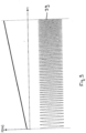
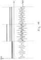
- Fig. 5 to Fig. 11 show the signal curves 35 to 41 in the time domain, which can be used, for example, as ultrasound transmission signals on the device 01.
- the frequency of the signal curve 35 to 41 is given in Hertz.
- the ultrasonic transmission signal can each have sections with increasing frequency, the frequency difference between the individual sections being equidistant.
- the signal curve 37 can also be varied with regard to the amplitude of the ultrasonic transmission signal depending on the respective transmission frequency.
- Fig. 8 represents a signal curve 38 of the ultrasonic transmission signal, each with an equidistantly increasing transmission frequency, the duration of the individual transmission sections becoming increasingly shortened, so that there is a constant number of runs in each section.
- the signal curve 39 of the ultrasonic transmission signal can also be emitted with a continuously increasing transmission frequency, for example a linear FM-modulated transmission signal.
- Fig. 10 represents a transmission signal curve 40 with four transmission frequencies superimposed on one another.
- the signal curve 41 of the ultrasonic transmission signal is generated by adding different transmission frequencies to a common transmission signal (superposition), whereby individual frequencies can be added or omitted in the different sections.
Landscapes
- Physics & Mathematics (AREA)
- Health & Medical Sciences (AREA)
- Life Sciences & Earth Sciences (AREA)
- Pathology (AREA)
- General Health & Medical Sciences (AREA)
- General Physics & Mathematics (AREA)
- Immunology (AREA)
- Chemical & Material Sciences (AREA)
- Analytical Chemistry (AREA)
- Biochemistry (AREA)
- Engineering & Computer Science (AREA)
- Acoustics & Sound (AREA)
- Signal Processing (AREA)
- Heart & Thoracic Surgery (AREA)
- Molecular Biology (AREA)
- Veterinary Medicine (AREA)
- Biophysics (AREA)
- Nuclear Medicine, Radiotherapy & Molecular Imaging (AREA)
- Radiology & Medical Imaging (AREA)
- Biomedical Technology (AREA)
- Public Health (AREA)
- Animal Behavior & Ethology (AREA)
- Surgery (AREA)
- Medical Informatics (AREA)
- Mathematical Physics (AREA)
- Spectroscopy & Molecular Physics (AREA)
- Neurology (AREA)
- Computer Vision & Pattern Recognition (AREA)
- Ultra Sonic Daignosis Equipment (AREA)
- Investigating Or Analyzing Materials By The Use Of Ultrasonic Waves (AREA)
Applications Claiming Priority (3)
| Application Number | Priority Date | Filing Date | Title |
|---|---|---|---|
| EP15177198 | 2015-07-17 | ||
| DE102015118226.2A DE102015118226A1 (de) | 2015-07-17 | 2015-10-26 | Vorrichtung zur Untersuchung von Materialien durch akustische Spektroskopie |
| PCT/EP2016/063863 WO2017012792A1 (de) | 2015-07-17 | 2016-06-16 | Vorrichtung zur untersuchung von materialien durch akustische spektroskopie |
Publications (3)
| Publication Number | Publication Date |
|---|---|
| EP3325960A1 EP3325960A1 (de) | 2018-05-30 |
| EP3325960B1 true EP3325960B1 (de) | 2023-11-01 |
| EP3325960C0 EP3325960C0 (de) | 2023-11-01 |
Family
ID=57630106
Family Applications (1)
| Application Number | Title | Priority Date | Filing Date |
|---|---|---|---|
| EP16734578.4A Active EP3325960B1 (de) | 2015-07-17 | 2016-06-16 | Vorrichtung zur untersuchung eines körpergewebes durch akustische spektroskopie |
Country Status (6)
| Country | Link |
|---|---|
| US (2) | US20180202978A1 (pl) |
| EP (1) | EP3325960B1 (pl) |
| DE (1) | DE102015118226A1 (pl) |
| ES (1) | ES2971162T3 (pl) |
| PL (1) | PL3325960T3 (pl) |
| WO (1) | WO2017012792A1 (pl) |
Families Citing this family (3)
| Publication number | Priority date | Publication date | Assignee | Title |
|---|---|---|---|---|
| CN108575107B (zh) * | 2016-01-20 | 2020-05-22 | 三菱电机株式会社 | 电力变换装置以及电力变换系统 |
| US10783346B2 (en) * | 2017-12-11 | 2020-09-22 | Invensense, Inc. | Enhancing quality of a fingerprint image |
| CN112362748B (zh) * | 2020-11-17 | 2022-01-28 | 中南大学 | 一种测量材料超声横波衰减系数与频率关系的方法和装置 |
Citations (1)
| Publication number | Priority date | Publication date | Assignee | Title |
|---|---|---|---|---|
| US20150041625A1 (en) * | 2013-08-06 | 2015-02-12 | Stmicroelectronics (Research & Development) Limited | Time to digital converter and applications thereof |
Family Cites Families (14)
| Publication number | Priority date | Publication date | Assignee | Title |
|---|---|---|---|---|
| US4930511A (en) | 1988-05-11 | 1990-06-05 | Lunar Radiation, Inc. | Ultrasonic densitometer device and method |
| DE4141123C1 (pl) | 1991-12-13 | 1993-03-18 | Kernforschungszentrum Karlsruhe Gmbh, 7500 Karlsruhe, De | |
| GB9200218D0 (en) | 1992-01-07 | 1992-02-26 | Univ Bradford | Method and apparatus for the identification of species |
| CA2078277C (en) * | 1992-09-15 | 1999-09-14 | Luc Piche | Ultrasonic characterization of polymer melts under processing conditions |
| US5492125A (en) | 1995-02-10 | 1996-02-20 | University Of Washington | Ultrasound signal processing apparatus |
| US6109098A (en) * | 1998-06-30 | 2000-08-29 | Doukhin Dispersion Technology, Inc. | Particle size distribution and zeta potential using acoustic and electroacoustic spectroscopy |
| DE19841154C2 (de) | 1998-09-09 | 2002-11-07 | Holger Loehmer | Verfahren und Vorrichtung zur Messung der Laufzeit von Schallwellen |
| US6553366B1 (en) | 1998-10-02 | 2003-04-22 | Ncr Corporation | Analytic logical data model |
| DE10324990B3 (de) | 2003-06-03 | 2004-11-04 | Visit Video-Stroboskop Innovations-Technik Gmbh & Co. Kg | Vorrichtung zur Untersuchung eines flüssigen oder gasförmigen Mediums |
| DE10353132B3 (de) * | 2003-11-14 | 2005-06-23 | Forschungszentrum Karlsruhe Gmbh | Verfahren zur Kompression von Daten |
| DE102005005386B3 (de) * | 2005-02-05 | 2006-07-13 | Forschungszentrum Karlsruhe Gmbh | Verfahren zur Reduktion von digitalisierten Daten in einem EMAT-Molch |
| DE202007017911U1 (de) | 2007-12-21 | 2008-03-06 | Fritsch, Thomas, Dr. | Vorrichtung zur Untersuchung der Eigenschaften eines Mediums |
| DE102008014300A1 (de) * | 2008-03-06 | 2009-09-10 | Technische Universität Dresden | Verfahren und Vorrichtung zur Bestimmung der Eigenschaften von Stoffgemischen |
| US8852103B2 (en) * | 2011-10-17 | 2014-10-07 | Butterfly Network, Inc. | Transmissive imaging and related apparatus and methods |
-
2015
- 2015-10-26 DE DE102015118226.2A patent/DE102015118226A1/de active Granted
-
2016
- 2016-06-16 EP EP16734578.4A patent/EP3325960B1/de active Active
- 2016-06-16 ES ES16734578T patent/ES2971162T3/es active Active
- 2016-06-16 US US15/743,385 patent/US20180202978A1/en not_active Abandoned
- 2016-06-16 WO PCT/EP2016/063863 patent/WO2017012792A1/de not_active Ceased
- 2016-06-16 PL PL16734578.4T patent/PL3325960T3/pl unknown
-
2021
- 2021-03-16 US US17/202,996 patent/US12326425B2/en active Active
Patent Citations (1)
| Publication number | Priority date | Publication date | Assignee | Title |
|---|---|---|---|---|
| US20150041625A1 (en) * | 2013-08-06 | 2015-02-12 | Stmicroelectronics (Research & Development) Limited | Time to digital converter and applications thereof |
Non-Patent Citations (4)
| Title |
|---|
| GERDS E J ET AL: "A CMOS TIME TO DIGITAL CONVERTER IC WITH 2 LEVEL ANALOG CAM", IEEE JOURNAL OF SOLID-STATE CIRCUITS, IEEE, USA, vol. 29, no. 9, 1 September 1994 (1994-09-01), pages 1068 - 1076, XP000475950, ISSN: 0018-9200, DOI: 10.1109/4.309902 * |
| HALL S J ET AL: "DIRECT TIME-TO-DIGITAL CONVERTER WITH MULTI-STOP FACILITY", NUCLEAR INSTRUMENTS AND METHODS,, vol. 140, 1 January 1977 (1977-01-01), pages 283 - 287, XP001436305 * |
| KARI MAATTA ET AL: "A High-Precision Time-to-Digital Converter for Pulsed Time-of-Flight Laser Radar Applications", IEEE TRANSACTIONS ON INSTRUMENTATION AND MEASUREMENT, IEEE SERVICE CENTER, PISCATAWAY, NJ, US, vol. 47, no. 2, 1 April 1998 (1998-04-01), XP011024486, ISSN: 0018-9456 * |
| MAVIN SWAPP: "TIME TO DIGITAL CONVERTER RESOLVES PICOSECONDS IN TIME INTERVAL MEASUREMENTS", TECHNICAL DEVELOPMENTS,, vol. 2, 1 January 1982 (1982-01-01), pages 53, XP001436857 * |
Also Published As
| Publication number | Publication date |
|---|---|
| WO2017012792A1 (de) | 2017-01-26 |
| ES2971162T3 (es) | 2024-06-03 |
| US12326425B2 (en) | 2025-06-10 |
| US20210325350A1 (en) | 2021-10-21 |
| PL3325960T3 (pl) | 2024-04-02 |
| US20180202978A1 (en) | 2018-07-19 |
| EP3325960C0 (de) | 2023-11-01 |
| EP3325960A1 (de) | 2018-05-30 |
| DE102015118226A1 (de) | 2017-01-19 |
Similar Documents
| Publication | Publication Date | Title |
|---|---|---|
| DE69526823T2 (de) | Gerät und Verfahren zum Analysieren von Information in Bezug auf physikalischen und geistigen Zustand | |
| DE69530686T2 (de) | Gerät zur gewebecharakterisierung mittels ultraschall | |
| DE69637337T2 (de) | Verbesserungen in Bezug auf physiologische Überwachung | |
| DE69729745T2 (de) | Vorrichtung zur bilderzeugung der prostata | |
| DE69309920T2 (de) | Prüfung des gehörs | |
| EP1324701A1 (de) | Ultraschalltomograph | |
| DE102016003133B4 (de) | Verfahren zur automatischen Bestimmung einer individuellen Funktion einer DPOAE-Pegelkarte eines menschlichen oder tierischen Gehörs | |
| EP3706636B1 (de) | Ultraschall-bilderzeugungssystem | |
| DE2645738A1 (de) | Ultraschallstrahlabtastung | |
| DE102017211895A1 (de) | Gewebecharakterisierung im medizinischen diagnostischen Ultraschall | |
| DE2657899A1 (de) | Verfahren und vorrichtung zur darstellung und kenntlichmachung von koerpern mittels ultraschall | |
| DE3104014A1 (de) | "ultraschall-abtaster" | |
| DE3643162A1 (de) | Nicht-invasives diagnoseverfahren fuer die gefaessstenose | |
| DE2745063A1 (de) | Richtungsempfindliches doppler-ultraschallsystem | |
| DE102016100367A1 (de) | Spärliche Verfolgung in Schallstrahlintensitätsimpuls-Bildgebung | |
| DE102014101814A1 (de) | Verfahren zur automatischen Auswertung eines Absens-EEG, Computerprogramm und Auswertegerät dafür | |
| EP3325960B1 (de) | Vorrichtung zur untersuchung eines körpergewebes durch akustische spektroskopie | |
| DE112010003150T5 (de) | Ultrasonografievorrichtung | |
| Klonowski | Chaotic dynamics applied to signal complexity in phase space and in time domain | |
| DE2637283A1 (de) | Gleichzeitige aufzeichnung von verbund- und einfach-ultraschall-abtastsignalen | |
| DE3406179C1 (de) | Vorrichtung zum Messen der Lage und Bewegung wenigstens eines Meßpunktes | |
| DE10248747B4 (de) | Breitstrahlabbildung | |
| WO2013091630A2 (de) | Verfahren zum untersuchen von menschlichem oder tierischem gewebe | |
| DE102013200058B3 (de) | Automatisierte Auswertung der Rohdaten eines MR-Spektrums | |
| WO2012055543A1 (de) | Anwendung eines zweidimensionalen analytischen signals in der sonographie |
Legal Events
| Date | Code | Title | Description |
|---|---|---|---|
| STAA | Information on the status of an ep patent application or granted ep patent |
Free format text: STATUS: THE INTERNATIONAL PUBLICATION HAS BEEN MADE |
|
| PUAI | Public reference made under article 153(3) epc to a published international application that has entered the european phase |
Free format text: ORIGINAL CODE: 0009012 |
|
| STAA | Information on the status of an ep patent application or granted ep patent |
Free format text: STATUS: REQUEST FOR EXAMINATION WAS MADE |
|
| 17P | Request for examination filed |
Effective date: 20180108 |
|
| AK | Designated contracting states |
Kind code of ref document: A1 Designated state(s): AL AT BE BG CH CY CZ DE DK EE ES FI FR GB GR HR HU IE IS IT LI LT LU LV MC MK MT NL NO PL PT RO RS SE SI SK SM TR |
|
| AX | Request for extension of the european patent |
Extension state: BA ME |
|
| DAV | Request for validation of the european patent (deleted) | ||
| DAX | Request for extension of the european patent (deleted) | ||
| RAP1 | Party data changed (applicant data changed or rights of an application transferred) |
Owner name: SONOVUM GMBH |
|
| STAA | Information on the status of an ep patent application or granted ep patent |
Free format text: STATUS: EXAMINATION IS IN PROGRESS |
|
| 17Q | First examination report despatched |
Effective date: 20200511 |
|
| GRAP | Despatch of communication of intention to grant a patent |
Free format text: ORIGINAL CODE: EPIDOSNIGR1 |
|
| STAA | Information on the status of an ep patent application or granted ep patent |
Free format text: STATUS: GRANT OF PATENT IS INTENDED |
|
| INTG | Intention to grant announced |
Effective date: 20230524 |
|
| GRAS | Grant fee paid |
Free format text: ORIGINAL CODE: EPIDOSNIGR3 |
|
| GRAA | (expected) grant |
Free format text: ORIGINAL CODE: 0009210 |
|
| STAA | Information on the status of an ep patent application or granted ep patent |
Free format text: STATUS: THE PATENT HAS BEEN GRANTED |
|
| AK | Designated contracting states |
Kind code of ref document: B1 Designated state(s): AL AT BE BG CH CY CZ DE DK EE ES FI FR GB GR HR HU IE IS IT LI LT LU LV MC MK MT NL NO PL PT RO RS SE SI SK SM TR |
|
| REG | Reference to a national code |
Ref country code: GB Ref legal event code: FG4D Free format text: NOT ENGLISH |
|
| REG | Reference to a national code |
Ref country code: CH Ref legal event code: EP |
|
| REG | Reference to a national code |
Ref country code: IE Ref legal event code: FG4D Free format text: LANGUAGE OF EP DOCUMENT: GERMAN |
|
| REG | Reference to a national code |
Ref country code: DE Ref legal event code: R096 Ref document number: 502016016197 Country of ref document: DE |
|
| U01 | Request for unitary effect filed |
Effective date: 20231122 |
|
| U07 | Unitary effect registered |
Designated state(s): AT BE BG DE DK EE FI FR IT LT LU LV MT NL PT SE SI Effective date: 20231128 |
|
| PG25 | Lapsed in a contracting state [announced via postgrant information from national office to epo] |
Ref country code: GR Free format text: LAPSE BECAUSE OF FAILURE TO SUBMIT A TRANSLATION OF THE DESCRIPTION OR TO PAY THE FEE WITHIN THE PRESCRIBED TIME-LIMIT Effective date: 20240202 |
|
| PG25 | Lapsed in a contracting state [announced via postgrant information from national office to epo] |
Ref country code: IS Free format text: LAPSE BECAUSE OF FAILURE TO SUBMIT A TRANSLATION OF THE DESCRIPTION OR TO PAY THE FEE WITHIN THE PRESCRIBED TIME-LIMIT Effective date: 20240301 |
|
| PG25 | Lapsed in a contracting state [announced via postgrant information from national office to epo] |
Ref country code: IS Free format text: LAPSE BECAUSE OF FAILURE TO SUBMIT A TRANSLATION OF THE DESCRIPTION OR TO PAY THE FEE WITHIN THE PRESCRIBED TIME-LIMIT Effective date: 20240301 Ref country code: GR Free format text: LAPSE BECAUSE OF FAILURE TO SUBMIT A TRANSLATION OF THE DESCRIPTION OR TO PAY THE FEE WITHIN THE PRESCRIBED TIME-LIMIT Effective date: 20240202 |
|
| PG25 | Lapsed in a contracting state [announced via postgrant information from national office to epo] |
Ref country code: RS Free format text: LAPSE BECAUSE OF FAILURE TO SUBMIT A TRANSLATION OF THE DESCRIPTION OR TO PAY THE FEE WITHIN THE PRESCRIBED TIME-LIMIT Effective date: 20231101 Ref country code: HR Free format text: LAPSE BECAUSE OF FAILURE TO SUBMIT A TRANSLATION OF THE DESCRIPTION OR TO PAY THE FEE WITHIN THE PRESCRIBED TIME-LIMIT Effective date: 20231101 |
|
| REG | Reference to a national code |
Ref country code: ES Ref legal event code: FG2A Ref document number: 2971162 Country of ref document: ES Kind code of ref document: T3 Effective date: 20240603 |
|
| U20 | Renewal fee for the european patent with unitary effect paid |
Year of fee payment: 9 Effective date: 20240619 |
|
| PG25 | Lapsed in a contracting state [announced via postgrant information from national office to epo] |
Ref country code: SK Free format text: LAPSE BECAUSE OF FAILURE TO SUBMIT A TRANSLATION OF THE DESCRIPTION OR TO PAY THE FEE WITHIN THE PRESCRIBED TIME-LIMIT Effective date: 20231101 |
|
| PG25 | Lapsed in a contracting state [announced via postgrant information from national office to epo] |
Ref country code: SM Free format text: LAPSE BECAUSE OF FAILURE TO SUBMIT A TRANSLATION OF THE DESCRIPTION OR TO PAY THE FEE WITHIN THE PRESCRIBED TIME-LIMIT Effective date: 20231101 Ref country code: SK Free format text: LAPSE BECAUSE OF FAILURE TO SUBMIT A TRANSLATION OF THE DESCRIPTION OR TO PAY THE FEE WITHIN THE PRESCRIBED TIME-LIMIT Effective date: 20231101 Ref country code: RO Free format text: LAPSE BECAUSE OF FAILURE TO SUBMIT A TRANSLATION OF THE DESCRIPTION OR TO PAY THE FEE WITHIN THE PRESCRIBED TIME-LIMIT Effective date: 20231101 |
|
| REG | Reference to a national code |
Ref country code: DE Ref legal event code: R097 Ref document number: 502016016197 Country of ref document: DE |
|
| PLBE | No opposition filed within time limit |
Free format text: ORIGINAL CODE: 0009261 |
|
| STAA | Information on the status of an ep patent application or granted ep patent |
Free format text: STATUS: NO OPPOSITION FILED WITHIN TIME LIMIT |
|
| 26N | No opposition filed |
Effective date: 20240802 |
|
| U1H | Name or address of the proprietor changed after the registration of the unitary effect |
Owner name: SONOVUM GMBH; DE |
|
| PG25 | Lapsed in a contracting state [announced via postgrant information from national office to epo] |
Ref country code: MC Free format text: LAPSE BECAUSE OF FAILURE TO SUBMIT A TRANSLATION OF THE DESCRIPTION OR TO PAY THE FEE WITHIN THE PRESCRIBED TIME-LIMIT Effective date: 20231101 |
|
| PG25 | Lapsed in a contracting state [announced via postgrant information from national office to epo] |
Ref country code: IE Free format text: LAPSE BECAUSE OF NON-PAYMENT OF DUE FEES Effective date: 20240616 |
|
| PGFP | Annual fee paid to national office [announced via postgrant information from national office to epo] |
Ref country code: PL Payment date: 20250523 Year of fee payment: 10 |
|
| PGFP | Annual fee paid to national office [announced via postgrant information from national office to epo] |
Ref country code: GB Payment date: 20250620 Year of fee payment: 10 |
|
| PGFP | Annual fee paid to national office [announced via postgrant information from national office to epo] |
Ref country code: NO Payment date: 20250617 Year of fee payment: 10 |
|
| PGFP | Annual fee paid to national office [announced via postgrant information from national office to epo] |
Ref country code: CZ Payment date: 20250605 Year of fee payment: 10 |
|
| U20 | Renewal fee for the european patent with unitary effect paid |
Year of fee payment: 10 Effective date: 20250625 |
|
| PGFP | Annual fee paid to national office [announced via postgrant information from national office to epo] |
Ref country code: ES Payment date: 20250718 Year of fee payment: 10 |
|
| PGFP | Annual fee paid to national office [announced via postgrant information from national office to epo] |
Ref country code: CH Payment date: 20250701 Year of fee payment: 10 |
|
| PG25 | Lapsed in a contracting state [announced via postgrant information from national office to epo] |
Ref country code: CY Free format text: LAPSE BECAUSE OF FAILURE TO SUBMIT A TRANSLATION OF THE DESCRIPTION OR TO PAY THE FEE WITHIN THE PRESCRIBED TIME-LIMIT; INVALID AB INITIO Effective date: 20160616 |
|
| PG25 | Lapsed in a contracting state [announced via postgrant information from national office to epo] |
Ref country code: HU Free format text: LAPSE BECAUSE OF FAILURE TO SUBMIT A TRANSLATION OF THE DESCRIPTION OR TO PAY THE FEE WITHIN THE PRESCRIBED TIME-LIMIT; INVALID AB INITIO Effective date: 20160616 |