EP3324703B1 - Induktionsheizeinrichtung für industrielle zwecke - Google Patents
Induktionsheizeinrichtung für industrielle zwecke Download PDFInfo
- Publication number
- EP3324703B1 EP3324703B1 EP16199592.3A EP16199592A EP3324703B1 EP 3324703 B1 EP3324703 B1 EP 3324703B1 EP 16199592 A EP16199592 A EP 16199592A EP 3324703 B1 EP3324703 B1 EP 3324703B1
- Authority
- EP
- European Patent Office
- Prior art keywords
- heating element
- induction
- magnetic yoke
- magnetic
- induction coil
- Prior art date
- Legal status (The legal status is an assumption and is not a legal conclusion. Google has not performed a legal analysis and makes no representation as to the accuracy of the status listed.)
- Active
Links
Images
Classifications
-
- H—ELECTRICITY
- H05—ELECTRIC TECHNIQUES NOT OTHERWISE PROVIDED FOR
- H05B—ELECTRIC HEATING; ELECTRIC LIGHT SOURCES NOT OTHERWISE PROVIDED FOR; CIRCUIT ARRANGEMENTS FOR ELECTRIC LIGHT SOURCES, IN GENERAL
- H05B6/00—Heating by electric, magnetic or electromagnetic fields
- H05B6/02—Induction heating
- H05B6/10—Induction heating apparatus, other than furnaces, for specific applications
- H05B6/105—Induction heating apparatus, other than furnaces, for specific applications using a susceptor
-
- H—ELECTRICITY
- H05—ELECTRIC TECHNIQUES NOT OTHERWISE PROVIDED FOR
- H05B—ELECTRIC HEATING; ELECTRIC LIGHT SOURCES NOT OTHERWISE PROVIDED FOR; CIRCUIT ARRANGEMENTS FOR ELECTRIC LIGHT SOURCES, IN GENERAL
- H05B6/00—Heating by electric, magnetic or electromagnetic fields
- H05B6/02—Induction heating
- H05B6/36—Coil arrangements
- H05B6/365—Coil arrangements using supplementary conductive or ferromagnetic pieces
Definitions
- the invention relates to an induction heating device for industrial purposes or applications and to a method for operating an induction heating device.
- US 2011/0297668 A1 shows a humidifier with an inductive heating device, which has a ferrite body with a cavity in which an induction coil is arranged.
- the heating device is arranged below a plate.
- a device for inductively heating a workpiece which has several heating modules.
- Each heating module has three poles, with a coil arranged around each pole.
- Each of the modules also has a lower part, so that heat can be dissipated from the upper part by means of a cooling medium.
- US 4,999,467 A discloses a low frequency electromagnetic induction heater having six induction coils electrically connected in a three-phase double delta connection.
- An induction heating device with an exciter for induction heating of a body is known.
- the induction heating device is intended, for example, to heat a cooking pot.
- the exciter comprises an iron core and a yoke as well as four magnetic poles and four excitation windings wound around the magnetic poles.
- US 2008/0303194 A1 shows various devices and methods for producing a polymer using induction heat.
- the device includes a mold with an upper mold plate and a lower mold plate.
- the upper mold plate has a magnetic surface that is heated by an induction coil in a lower mold plate.
- the object of the invention is to provide a heating system for industrial applications or purposes, such as in a packaging machine or the like, wherein a homogeneous temperature distributed over a surface is to be provided, for example for an adhesive process or sealing process.
- an induction heating device for industrial purposes or industrial applications with at least one surface inductor having an induction coil to which alternating voltage can be applied and with a heating element that can be heated by the surface inductor and that has a surface facing the surface inductor and with a magnetic yoke for guiding the magnetic field generated or that can be generated by the induction coil, wherein the induction coil and the magnetic yoke are designed in such a way that a constant power input per surface area for heating the heating element takes place via the surface of the heating element facing the surface inductor and a homogeneous temperature field is generated or can be generated in the heating element via the surface facing the surface inductor, wherein the induction coil has at least one uneven winding, wherein in field areas with a strong coupling to the heating element the distances between the turns are increased, while in field areas with a weak coupling the turns are spaced closer together, wherein the induction heating device is further developed in that the surface inductor is connected to at least one local position has an additional turn
- the induction heating device has an electrical coil as an induction coil, by means of which a magnetic field with alternating polarization can be generated to generate heat in an electrically conductive heating element, in particular a heating plate or the like, penetrated by the alternating magnetic field. Due to the alternating electromagnetic field of the induction coil when the induction coil is subjected to alternating voltage, eddy currents are induced in the heating element and remagnetizations are generated, whereby due to remagnetization losses and ohmic losses caused by the eddy currents, the power transferred into the radiator is converted into heat, thereby causing a homogeneous temperature distribution in the radiator.
- the induction heating device is used, for example, in industrial induction heating systems for mechanical engineering, in which in particular a temperature field with a low temperature gradient or with a constant temperature, i.e. a homogenized temperature field for the bonding or sealing processes or the like, is required.
- induction heating device in induction hardening systems, induction heating furnaces, induction heating rollers or induction cookers with control units where a homogeneous temperature distributed over a large area with tight tolerances is required, for example for bonding or sealing processes.
- the field distribution of the magnetic field is determined by the shape of the induction coil and the design of the magnetic yoke for guiding the (alternating) magnetic field.
- the magnetic yoke guides the magnetic field generated by the induction coil in such a way that the magnetic field is coupled preferably or optimally into the soft magnetic, electrically conductive radiator.
- this makes it possible to heat the radiator or the heating plate, which is arranged opposite the induction coil, in such a way that the radiator has a homogenized temperature field on its heat-emitting side or contact side.
- the induction coil and the magnetic yoke are designed in such a way and, if necessary, coordinated with one another in their geometric dimensions, it is possible for a predetermined, constant power per area to be transmitted by means of the alternating magnetic field over the entire surface of the heating element facing the surface inductor, whereby a homogeneous temperature field is generated in the heating element over the entire surface at a predetermined temperature with a tolerance of less than ⁇ 5%, preferably less than ⁇ 3% or less than ⁇ 1%.
- the induction coil is designed as a cylindrical coil or flat coil and/or that the heating element is designed as a heating plate.
- the heating element or the heating plate has a flat surface facing the induction coil.
- the heating element is preferably designed as a cuboid heating plate.
- the magnetic yoke is designed such that the induction coil is surrounded by the magnetic yoke or is accommodated therein.
- the induction coil has at least one uneven winding, since this achieves a uniform coupling of the magnetic field over the entire coupling surface of the coil to the radiator, in particular heating plate, due to an uneven arrangement of the winding of the coil, for example as a flat coil, since this increases the distances between the windings, in particular individually, in field areas with a strong coupling to the radiator, while in field areas with weak coupling the turns are closer together.
- a predetermined, preferably optimal, field distribution of the magnetic field is created for a homogeneous temperature distribution in the radiator or heating plate.
- the surface inductor has an additional winding at at least one local position in a different winding plane than the winding plane of the induction coil.
- the surface inductor has at least one local additional coil, preferably at a predetermined position, in addition to the induction coil, so that the coupling between the induction coil and the heating element is influenced in a targeted manner.
- the additional winding(s) or additional coil(s) are in areas of weak coupling or in areas of local modifications of the coil winding course, for example in the case of flat or spatially formed meandering serpentine lines.
- an embodiment of the induction heating device is characterized in that the magnetic yoke comprises soft magnetic material, in particular soft magnetic ferrite, or is made of soft magnetic material, in particular ferrite.
- the magnetic yoke is in particular made of soft magnetic ferrite material, which is designed or shaped in such a way that the coupling of the magnetic field in areas that are strongly magnetically coupled to the heating element is weakened by sections of the magnetic yoke and the coupling of the magnetic field in areas that are weakly magnetically coupled to the heating element is strengthened by sections of the magnetic yoke.
- the magnetic yoke has at least one recess and/or the magnetic yoke has different cross-sections in individual sections, so that the field profile of the magnetic field can be modified or modified.
- the magnetic yoke is thus designed in such a way that the flow of the magnetic flux strengthens the coupling areas of the heating element with a weak coupling to the magnetic yoke and weakens the coupling areas of the heating element with a weak coupling to the magnetic yoke.
- the end faces of the magnetic yoke facing the heating element are adapted or designed in such a way that the flow of the magnetic flux is amplified in at least one coupling region of the heating element with weak coupling to the magnetic yoke and/or the flow the magnetic flux is weakened in at least one coupling region of the radiator with strong coupling to the magnetic yoke.
- the distance between the end faces of the magnet yoke facing the heating body and the heating body is adjustable and/or that at least two areas of the end faces of the magnet yoke facing the heating body have different distances from the heating body.
- the end faces of the magnet yoke are designed in their cross-section and/or in their position relative to the heating body such that the distance of the end faces from the heating body and thus also an air gap between the Magnetic yoke and the heating element are locally adjustable.
- the inner transition of the magnetic yoke to the heating element in a magnetic yoke with a flat coil is set back or stepped compared to a minimum possible distance and/or the outer transition of the magnetic yoke to the heating element is not designed in the spatially maximum possible configuration.
- the magnetic yoke can be designed in such a way that the end faces of the magnetic yoke to the heating plate have different distances in several sections.
- the flow of the magnetic flux can be specifically influenced or caused by amplification or weakening by using different cross-sections of the magnetic yoke in different sections of the magnetic yoke.
- the distances can also be formed by a linear or non-linear course from the surface of the heating plate to the front face of the magnetic yoke.
- the induction heating device provides a homogeneous temperature field in the radiator or the heating plate, whereby hotspots in the radiator are avoided according to the invention.
- the object is achieved by a method for operating an induction heating device described above for industrial purposes or industrial applications, wherein the induction coil and the magnetic yoke are designed such that A constant power input per area is applied to heat the radiator over the surface of the radiator facing the surface inductor and a homogeneous temperature field is generated in the radiator over the surface facing the surface inductor.
- the induction coil and the magnetic yoke are designed such that A constant power input per area is applied to heat the radiator over the surface of the radiator facing the surface inductor and a homogeneous temperature field is generated in the radiator over the surface facing the surface inductor.
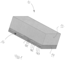
- Fig.1 shows in a perspective view of a half model an induction heating device 10 for industrial applications or purposes.
- the induction heating device 10 has an electrically conductive heating plate 12 which is cuboid-shaped and has flat surfaces.
- a magnetic yoke corresponding to the external dimensions of the heating plate 12 is arranged below the heating plate 12, with an induction coil 16 being accommodated in the magnetic yoke 14.
- the induction coil 16 is designed as a flat coil, with the turns of the induction coil 16 being arranged in a spiral shape.
- the induction coil 16 is operated or charged with an alternating electrical voltage so that an alternating electromagnetic field is generated by the induction coil 16, so that the alternating electromagnetic field of the induction coil 16 generates eddy currents and remagnetization in the heating plate 12, whereby the power is transferred to the heating plate 12, so that a homogeneous temperature distribution is achieved in the heating plate 12 over the entire surface of the heating plate 12 that faces the induction coil.
- the heating plate 12 is made of a soft magnetic and electrically conductive material.
- the induction coil 16 has turns 161, 162, 163 which are spaced apart at different distances from one another, for example the inner turns 161 are spaced more closely apart than the middle turns 162.
- the outer turns 163 are in turn spaced apart at a smaller distance than the middle turns 162.
- the closely spaced turns 161 are arranged in field areas with a weak coupling to the heating plate 12, while the further apart (middle) turns 162 are arranged in areas with a strong coupling.
- the outer, more closely spaced turns 163 are also arranged in field areas with a strong coupling between the induction coil 16 and the heating plate 12.
- the magnetic yoke 14 is preferably made of soft magnetic ferrite material, with the magnetic yoke 14 being designed in such a way that areas that are strongly magnetically coupled to the heating plate 12 experience a weakening of the coupling and areas that are weakly magnetically coupled are strengthened.
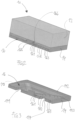
- the induction heating device 10 shown differs from that shown in Fig.1 illustrated induction heating device 10 in that in the area of weak coupling an additional coil 166 is additionally formed at a local point above the induction coil 16 designed as a flat coil.
- an additional winding 165 can also be arranged above the (normal) winding level of the induction coil 16.
- the additional winding can also be arranged below the winding level of the induction coil 16.
- Fig.3 In the perspective view of the magnetic yoke 14, it is shown that the magnetic yoke 14 has recesses 141 on the underside, which are arranged in the region of the strong coupling of the magnetic field with the heating plate 12.
- Fig.3 shown that the magnet yoke 14 has an end face 142 facing the heating plate 12, wherein Modification of the coupling areas, the front surface 142 can have flattened areas 143, for example on the long side. This varies the distance between the magnet yoke 14 and the heating plate 12. Furthermore, the front surface 142 can also have elevations or raised areas at local positions.
Landscapes
- Physics & Mathematics (AREA)
- Electromagnetism (AREA)
- General Induction Heating (AREA)
Description
- Die Erfindung betrifft eine Induktionsheizeinrichtung für industrielle Zwecke oder Anwendungen sowie ein Verfahren zum Betreiben einer Induktionsheizeinrichtung.
- Im Stand der Technik ist bekannt, dass industrielle Verpackungsmaschinen zum Verpacken von Packgut zum Versiegeln oder Formen sowie zum Verkleben der Verpackung Heiz-, Form- und/oder Siegelwerkzeuge oder dergleichen aufweisen. Beispielsweise ist in
DE 10 2007 059 812 A1 eine Verpackungsmaschine zum Verpacken von Tabakgut mit einer Induktionsheizung als Heizung offenbart. -
US 2011/0297668 A1 zeigt einen Luftbefeuchter mit einer induktiven Heizvorrichtung, welche einen Ferritkörper mit einem Hohlraum aufweist, in dem eine Induktionsspule angeordnet ist. Die Heizvorrichtung ist unterhalb einer Platte angeordnet. - Aus
WO 00/35248 A1 -
US 4,999,467 A offenbart eine niederfrequenz-elektromagnetische Induktionsheizung mit sechs Induktionsspulen, die in einer dreiphasigen Doppel-Dreieck-Verbindung elektrisch miteinander verbunden sind. - Aus
FR 2 196 568 A1 -
US 2008/0303194 A1 zeigt verschiedene Vorrichtungen und Verfahren zum Herstellen eines Polymers mittels Induktionshitze. Die Vorrichtung umfasst eine Gussform mit einer oberen Gussplatte und einer unteren Gussplatte. Die obere Gussplatte weist eine magnetische Oberfläche auf, die durch eine Induktionsspule in einer unteren Gussplatte erwärmt wird. - Die Aufgabe der Erfindung besteht darin, ein Heizsystem für industrielle Anwendungen oder Zwecke, wie zum Beispiel bei einer Verpackungsmaschine oder dergleichen, bereitzustellen, wobei eine flächig verteilte homogene Temperatur, zum Beispiel für einen Klebeprozess oder Versiegelungsprozess, bereitgestellt werden soll.
- Gelöst wird diese Aufgabe durch eine Induktionsheizeinrichtung für industrielle Zwecke oder industrielle Anwendungen mit wenigstens einem eine mit Wechselspannung beaufschlagbare Induktionsspule aufweisenden Flächeninduktor und mit einem durch den Flächeninduktor erwärmbaren Heizkörper, der eine dem Flächeninduktor zugewandte Fläche aufweist und mit einem Magnetjoch für die Führung des von der Induktionsspule erzeugten oder erzeugbaren Magnetfelds, wobei die Induktionsspule und das Magnetjoch derart ausgebildet sind, dass über die dem Flächeninduktor zugewandte Fläche des Heizkörpers ein konstanter Leistungseintrag pro Fläche zur Erwärmung des Heizkörpers erfolgt und im Heizkörper über die dem Flächeninduktor zugewandte Fläche ein homogenes Temperaturfeld erzeugt wird oder erzeugbar ist, wobei die Induktionsspule wenigstens eine ungleichmäßige Wicklung aufweist, wobei in Feldbereichen mit starker Kopplung zum Heizkörper die Abstände zwischen den Windungen vergrößert sind, während in Feldbereichen mit schwacher Kopplung die Windungen einen engeren Abstand aufweisen, wobei die Induktionsheizeinrichtung dadurch fortgebildet ist, dass der Flächeninduktor neben der Induktionsspule an wenigstens einer lokalen Position eine Zusatzwindung in einer anderen Wicklungsebene als die Wicklungsebene der Induktionsspule aufweist.
- Gemäß der Erfindung weist die Induktionsheizeinrichtung als Induktionsspule eine elektrische Spule auf, mittels der ein Magnetfeld in wechselnder Polarisierung zur Erzeugung von Wärme in einem von dem Wechselmagnetfeld durchdrungenen, elektrisch leitfähigen Heizkörper, insbesondere Heizplatte oder dergleichen, erzeugt werden kann. Durch das elektromagnetische Wechselfeld der Induktionsspule bei Beaufschlagung der Induktionsspule mit Wechselspannung werden in dem Heizkörper Wirbelströme induziert und Ummagnetisierungen erzeugt, wobei aufgrund von Ummagnetisierungsverlusten und von ohmschen Verlusten durch die Wirbelströme die in den Heizkörper übertragene Leistung in Wärme umgewandelt wird, wodurch eine homogene Temperaturverteilung in dem Heizkörper bewirkt wird.
- Die erfindungsgemäße Induktionsheizeinrichtung wird beispielsweise bei industriellen Induktionsheizanlagen für den Maschinenbau eingesetzt oder verwendet, bei denen insbesondere ein Temperaturfeld mit einem geringen Temperaturgradienten oder mit einer konstanten Temperatur, d.h. einem homogenisierten Temperaturfeld für die Klebe- oder Siegelprozesse oder dergleichen, benötigt wird.
- Beispielsweise ist es möglich, die Induktionsheizeinrichtung bei Induktionshärteanlagen, Induktionsheizöfen, Induktionsheizwalzen oder Induktionsherden mit Regeleinheiten einzusetzen bzw. zu verwenden, bei denen eine flächig verteilte homogene Temperatur mit engen Toleranzen zum Beispiel für Klebeprozesse oder Siegelprozesse erforderlich ist.
- Ist beispielsweise der Heizkörper als flächige Heizplatte ausgebildet, wird die Feldverteilung des Magnetfelds durch die Form der Induktionsspule und die Gestaltung des Magnetjochs zur Führung des (Wechsel-)Magnetfelds festgelegt. Durch das Magnetjoch wird das von der Induktionsspule erzeugte Magnetfeld derart geführt, dass eine bevorzugte oder optimale Einkopplung des Magnetfelds in den weichmagnetischen, elektrisch leitenden Heizkörper erfolgt. Insbesondere ist es dadurch möglich, den Heizkörper bzw. die Heizplatte, die der Induktionsspule gegenüber angeordnet ist, derart zu erwärmen, dass der Heizkörper an seiner wärmeabgebenden Seite bzw. Kontaktseite ein homogenisiertes Temperaturfeld aufweist.
- Dadurch, dass die Induktionsspule und das Magnetjoch derart ausgebildet und gegebenenfalls in ihren geometrischen Abmessungen aufeinander abgestimmt sind, ist es möglich, dass über die gesamte Fläche des Heizkörpers, die dem Flächeninduktor zugewandt ist, eine vorbestimmte, konstante Leistung pro Fläche mittels des magnetischen Wechselfelds übertragen wird, wodurch im Heizkörper über die gesamte Fläche ein homogenes Temperaturfeld bei einer vorbestimmten Temperatur mit einer Toleranz von weniger als ±5 %, vorzugsweise weniger als ± 3 % oder weniger als ± 1 %, erzeugt wird.
- Dazu ist in einer Ausgestaltung vorgesehen, dass die Induktionsspule als Zylinderspule oder Flachspule ausgebildet ist und/oder dass der Heizkörper als Heizplatte ausgebildet ist. Insbesondere weist der Heizkörper bzw. die Heizplatte eine der Induktionsspule zugewandte ebene Oberfläche auf. Vorzugsweise ist der Heizkörper als quaderförmige Heizplatte ausgebildet.
- Vorzugsweise ist das Magnetjoch derart ausgebildet, dass die Induktionsspule von dem Magnetjoch umgeben ist oder darin aufgenommen ist.
- Um eine homogene Verteilung der Temperatur, vorzugsweise mit einer engen Toleranz, im Heizkörper zu erzeugen, ist gemäß der Erfindung vorgesehen, dass die Induktionsspule wenigstens eine ungleichmäßige Wicklung aufweist, da hierdurch aufgrund einer ungleichmäßigen Anordnung der Wicklung der Spule, beispielsweise als Flachspule, über die gesamte Koppelfläche der Spule zum Heizkörper, insbesondere Heizplatte, eine gleichmäßige Kopplung des Magnetfeldes erreicht wird, da hierdurch in Feldbereichen mit starker Kopplung zum Heizkörper die Abstände zwischen den Windungen, insbesondere individuell, vergrößert sind, während in Feldbereichen mit schwacher Kopplung die Windungen einen engeren Abstand aufweisen. Dadurch ergibt sich eine nicht äquidistante oder gleichmäßig gewickelte Spule, so dass über die gesamte Koppelfläche der Induktionsspule zum Heizkörper eine einheitliche oder im Wesentlichen gleichförmige Kopplung unter Berücksichtigung unterschiedlicher Koppelbereiche erreicht wird.
- Durch die Variation der Abstände zwischen den Windungen der Induktionsspule wird eine vorbestimmte, vorzugsweise optimale, Feldverteilung des Magnetfeldes für eine homogene Temperaturverteilung in dem Heizkörper oder der Heizplatte ausgebildet.
- Der Flächeninduktor weist neben der Induktionsspule an wenigstens einer lokalen Position eine Zusatzwindung in einer anderen Wicklungsebene als die Wicklungsebene der Induktionsspule auf.
- Darüber hinaus ist es bei der Induktionsheizeinrichtung bevorzugt, dass der Flächeninduktor neben der Induktionsspule wenigstens eine lokale Zusatzspule, vorzugsweise an einer vorbestimmten Position, aufweist, so dass hierdurch die Kopplung zwischen der Induktionsspule und dem Heizkörper gezielt beeinflusst wird. Beispielsweise ist es durch die Bereitstellung von wenigstens einer lokalen Zusatzwindung oder mehrerer Zusatzwindungen, zum Beispiel in einer anderen Wicklungsebene der Spule, oder durch die Verwendung von wenigstens einer kleinen lokalen Zusatzspule in Bereichen mit einer schwachen Kopplung des Magnetfelds zum Heizkörper möglich, die Kopplung zwischen der Heizspule und dem Heizkörper gezielt zu beeinflussen. Insbesondere sind die Zusatzwindung(en) oder Zusatzspule(n) in Bereichen schwacher Kopplung oder in Bereichen von lokalen Modifikationen des Spulenwindungsverlaufs, zum Beispiel bei ebenen oder räumlich ausgebildeten mäandrierenden Schlangenlinien, möglich.
- Außerdem zeichnet sich eine Ausgestaltung der Induktionsheizeinrichtung dadurch aus, dass das Magnetjoch weichmagnetisches Material, insbesondere weichmagnetischer Ferrit, aufweist oder aus weichmagnetischem Material, insbesondere Ferrit, hergestellt ist. Hierbei ist insbesondere das Magnetjoch aus weichmagnetischem Ferritmaterial gebildet, das derart ausgebildet oder geformt ist, dass die Kopplung des Magnetfelds bei magnetisch stark zum Heizkörper gekoppelten Bereichen durch Abschnitte des Magnetjochs abgeschwächt wird und die Kopplung des Magnetfelds bei magnetischschwach zum Heizkörper gekoppelten Bereichen durch Abschnitte des Magnetjochs verstärkt wird.
- Des Weiteren ist es zur Ausbildung einer stärkeren oder abgeschwächten Kopplung zwischen der Induktionsspule und dem Heizkörper vorgesehen, dass das Magnetjoch wenigstens eine Aussparung aufweist und/oder das Magnetjoch in einzelnen Abschnitten unterschiedliche Querschnitte aufweist, so dass der Feldverlauf des Magnetfelds modifizierbar oder modifiziert ist. Dadurch wird das Magnetjoch derart ausgestaltet, dass der Flussverlauf des magnetischen Flusses die Koppelbereiche des Heizkörpers mit schwacher Kopplung zum Magnetjoch verstärkt und die Koppelbereiche des Heizkörpers mit schwacher Kopplung zum Magnetjoch abschwächt.
- Dazu ist in einer Ausgestaltung vorgesehen, dass die dem Heizkörper zugewandten Stirnflächen des Magnetjochs derart angepasst oder ausgebildet sind, dass der Flussverlauf des magnetischen Flusses bei wenigstens einem Koppelbereich des Heizkörpers mit schwacher Kopplung zum Magnetjoch verstärkt wird und/oder der Flussverlauf des magnetischen Flusses bei wenigstens einem Koppelbereich des Heizkörpers mit starker Kopplung zum Magnetjoch abgeschwächt wird.
- Ferner ist es bei einer Ausführungsform der Induktionsheizeinrichtung vorgesehen, dass der Abstand zwischen den dem Heizkörper zugewandten Stirnflächen des Magnetjochs und dem Heizkörper einstellbar ist und/oder dass wenigstens zwei Bereiche der dem Heizkörper zugewandten Stirnflächen des Magnetjochs unterschiedliche Abstände zum Heizkörper aufweisen. Insbesondere werden die Stirnflächen des Magnetjochs in ihrem Querschnitt und/oder in ihrer Position zum Heizkörper so gestaltet, dass der Abstand der Stirnflächen zum Heizkörper und somit auch ein Luftspalt zwischen dem Magnetjoch und dem Heizkörper lokal einstellbar sind. Beispielsweise wird der innere Übergang des Magnetjochs zum Heizkörper bei einem Magnetjoch mit Flachspule gegenüber einem minimal möglichen Abstand zurückgesetzt bzw. gestuft ausgebildet und/oder der äußere Übergang des Magnetjochs zum Heizkörper nicht in der räumlich maximal möglichen Ausbildung ausgeführt. Insbesondere kann das Magnetjoch derart ausgebildet sein, dass in mehreren Abschnitten die Stirnflächen des Magnetjochs zur Heizplatte verschiedene Abstände aufweisen.
- Darüber hinaus können auch durch unterschiedliche Querschnitte des Magnetjochs in verschiedenen Abschnitten des Magnetjochs der Flussverlauf des magnetischen Flusses durch Verstärkung oder Abschwächung gezielt beeinflusst bzw. bewirkt werden. Außerdem können auch die Abstände durch einen linearen oder nichtlinearen Verlauf gegenüber der Oberfläche der Heizplatte zur Stirnfläche des Magnetjochs gebildet werden. Darüber hinaus ist es ebenfalls möglich, zur lokalen Schwächung des Magnetfelds durch magnetische Engpässe, beispielsweise in Form einer Präzisierung des Jochquerschnitts oder durch Verwendung von lokalen Jochabschnitten aus magnetisch gegenüber dem restlichen Jochmaterial schlechter leitendem Ferritmaterial, das Magnetfeld zu schwächen.
- Insgesamt wird durch die erfindungsgemäße Induktionsheizeinrichtung ein homogenes Temperaturfeld in dem Heizkörper bzw. der Heizplatte bereitgestellt, wobei erfindungsgemäß Hotspots in dem Heizkörper vermieden werden.
- Ferner wird die Aufgabe gelöst durch ein Verfahren zum Betreiben einer voranstehend beschriebenen Induktionsheizeinrichtung für industrielle Zwecke oder industrielle Anwendungen, wobei die Induktionsspule und das Magnetjoch derart ausgebildet sind, dass über die dem Flächeninduktor zugewandte Fläche des Heizkörpers ein konstanter Leistungseintrag pro Fläche zur Erwärmung des Heizkörpers erfolgt und im Heizkörper über die dem Flächeninduktor zugewandte Fläche ein homogenes Temperaturfeld erzeugt wird. Zur Vermeidung von Wiederholungen wird auf die obigen Ausführungen ausdrücklich verwiesen.
- Es zeigen:
- Fig. 1
- schematisch eine perspektivische Ansicht einer Induktionsheizeinrichtung in einer Halbmodelldarstellung;
- Fig. 2
- schematisch ein weiteres Ausführungsbeispiel einer Induktionsheizeinrichtung in einer perspektivischen Ansicht einer Halbmodelldarstellung und
- Fig. 3
- schematisch eine perspektivische Ansicht eines Magnetjochs mit einer Induktionsspule für eine Induktionsheizeinrichtung in einer perspektivischen Ansicht.
- In den Zeichnungen sind jeweils gleiche oder gleichartige Elemente und/oder Teile mit denselben Bezugsziffern versehen, so dass von einer erneuten Vorstellung jeweils abgesehen wird.
-
Fig. 1 zeigt in einer perspektivischen Darstellung eines Halbmodells eine Induktionsheizeinrichtung 10 für industrielle Anwendungen oder Zwecke. Die Induktionsheizeinrichtung 10 weist eine elektrisch leitfähige Heizplatte 12 auf, die quaderförmig ausgebildet ist und ebene Oberflächen aufweist. - Unterhalb der Heizplatte 12 ist ein Magnetjoch entsprechend den äußeren Abmessungen der Heizplatte 12 angeordnet, wobei in dem Magnetjoch 14 eine Induktionsspule 16 aufgenommen ist. Die Induktionsspule 16 ist hierbei als Flachspule ausgebildet, wobei die Windungen der Induktionsspule 16 spiralförmig angeordnet sind.
- Die Induktionsspule 16 wird mit einer elektrischen Wechselspannung betrieben bzw. beaufschlagt, so dass ein elektromagnetisches Wechselfeld durch die Induktionsspule 16 erzeugt wird, so dass durch das elektromagnetische Wechselfeld der Induktionsspule 16 Wirbelströme und Ummagnetisierungen in der Heizplatte 12 erzeugt werden, wodurch die Leistung in die Heizplatte 12 übertragen wird, so dass eine homogene Temperaturverteilung in der Heizplatte 12 über die gesamte Fläche der Heizplatte 12, die der Induktionsspule zugewandt ist, bewirkt wird. Die Heizplatte 12 ist hierbei aus einem weichmagnetischen und elektrisch leitenden Material hergestellt.
- Um eine optimierte Induktionskopplung zu erreichen, weist die Induktionsspule 16 Windungen 161, 162, 163 auf, die zueinander unterschiedliche Abstände aufweisen, zum Beispiel sind die inneren Windungen 161 enger zueinander beabstandet als die mittleren Windungen 162. Die äußeren Windungen 163 sind ihrerseits in einem kleineren Abstand zueinander beabstandet als die mittleren Windungen 162.
- Beispielsweise sind die eng nebeneinander liegenden Windungen 161 in Feldbereichen mit schwacher Kopplung zur Heizplatte 12 angeordnet, während die weiter auseinanderliegenden (mittleren) Windungen 162 in Bereichen mit starker Kopplung angeordnet sind. Die äußeren enger nebeneinanderliegenden Windungen 163 sind ebenfalls in Feldbereichen mit einer starken Kopplung zwischen der Induktionsspule 16 und der Heizplatte 12 angeordnet. Das Magnetjoch 14 ist vorzugsweise aus weichmagnetischem Ferritmaterial hergestellt, wobei das Magnetjoch 14 derart ausgebildet ist, dass magnetisch stark zur Heizplatte 12 gekoppelte Bereiche eine Abschwächung der Kopplung erfahren und magnetisch schwach gekoppelte Bereiche verstärkt werden.
- Die in
Fig. 2 gezeigte Induktionsheizeinrichtung 10 unterscheidet sich von der inFig. 1 dargestellten Induktionsheizeinrichtung 10 dadurch, dass im Bereich der schwachen Kopplung zusätzlich an einer lokalen Stelle eine Zusatzspule 166 oberhalb der als Flachspule ausgebildeten Induktionsspule 16 ausgebildet ist. Darüber hinaus kann auch in diesem Bereich der schwachen Kopplung eine Zusatzwindung 165 oberhalb der (normalen) Wicklungsebene der Induktionsspule 16 angeordnet sein. In einer weiteren Ausgestaltung kann die Zusatzwindung auch unterhalb der Wicklungsebene der Induktionsspule 16 angeordnet sein. - In
Fig. 3 ist in der perspektivischen Darstellung des Magnetjochs 14 dargestellt, dass das Magnetjoch 14 an der Unterseite Aussparungen 141 aufweist, die im Bereich der starken Kopplung des Magnetfelds mit der Heizplatte 12 angeordnet sind. - Darüber hinaus ist in
Fig. 3 gezeigt, dass das Magnetjoch 14 eine der Heizplatte 12 zugewandte Stirnfläche 142 aufweist, wobei zur Modifikation der Koppelbereiche die Stirnfläche 142 Abflachungen 143 zum Beispiel an der Längsseite aufweisen kann. Hierdurch wird der Abstand zwischen dem Magnetjoch 14 und der Heizplatte 12 variiert. Ferner kann die Stirnfläche 142 auch an lokalen Positionen Erhebungen oder Erhöhungen aufweisen. - Im Rahmen der Erfindung sind Merkmale, die mit "insbesondere" oder "vorzugsweise" gekennzeichnet sind, als fakultative Merkmale zu verstehen.
-
- 10
- Induktionsheizeinrichtung
- 12
- Heizplatte
- 14
- Magnetjoch
- 16
- Induktionsspule
- 141
- Aussparung
- 142
- Stirnfläche
- 143
- Abflachung
- 161
- Windung
- 162
- Windung
- 163
- Windung
- 165
- Zusatzwindung
- 166
- Zusatzspulen
Claims (8)
- Induktionsheizeinrichtung (10) für industrielle Zwecke oder industrielle Anwendungen mit wenigstens einem eine mit Wechselspannung beaufschlagbare Induktionsspule (16) aufweisenden Flächeninduktor und mit einem durch den Flächeninduktor erwärmbaren Heizkörper (12), der eine dem Flächeninduktor zugewandte Fläche aufweist, und mit einem Magnetjoch (14) für die Führung des von der Induktionsspule (16) erzeugten oder erzeugbaren Magnetfelds, wobei die Induktionsspule (16) und das Magnetjoch (14) derart ausgebildet sind, dass über die dem Flächeninduktor zugewandte Fläche des Heizkörpers (12) ein konstanter Leistungseintrag pro Fläche zur Erwärmung des Heizkörpers (12) erfolgt und im Heizkörper über die dem Flächeninduktor zugewandte Fläche ein homogenes Temperaturfeld erzeugt wird oder erzeugbar ist, wobei die Induktionsspule (16) wenigstens eine ungleichmäßige Wicklung aufweist, wobei in Feldbereichen mit starker Kopplung zum Heizkörper (12) die Abstände zwischen den Windungen vergrößert sind, während in Feldbereichen mit schwacher Kopplung die Windungen einen engeren Abstand aufweisen, dadurch gekennzeichnet, dass der Flächeninduktor neben der Induktionsspule (16) an wenigstens einer lokalen Position eine Zusatzwindung (166) in einer anderen Wicklungsebene als die Wicklungsebene der Induktionsspule (16) aufweist.
- Induktionsheizeinrichtung (10) nach Anspruch 1, dadurch gekennzeichnet, dass die Induktionsspule (16) als Zylinderspule oder Flachspule ausgebildet ist und/oder dass der Heizkörper (12) als Heizplatte (12) ausgebildet ist.
- Induktionsheizeinrichtung (10) nach Anspruch 1 oder 2, dadurch gekennzeichnet, dass der Flächeninduktor neben der Induktionsspule (16) wenigstens eine lokale Zusatzspule (165), vorzugsweise an einer vorbestimmten Position, aufweist.
- Induktionsheizeinrichtung (10) nach einem der Ansprüche 1 bis 3, dadurch gekennzeichnet, dass das Magnetjoch (14) weichmagnetisches Material, insbesondere weichmagnetischer Ferrit, aufweist oder aus weichmagnetischem Material, insbesondere Ferrit, hergestellt ist.
- Induktionsheizeinrichtung (10) nach einem der Ansprüche 1 bis 4, dadurch gekennzeichnet, dass das Magnetjoch (14) wenigstens eine Aussparung aufweist und/oder das Magnetjoch (14) unterschiedliche Querschnitte aufweist, so dass der Feldverlauf des Magnetfelds modifizierbar oder modifiziert ist.
- Induktionsheizeinrichtung (10) nach einem der Ansprüche 1 bis 5, dadurch gekennzeichnet, dass die dem Heizkörper (12) zugewandten Stirnflächen des Magnetjochs (14) derart angepasst oder ausgebildet sind, dass der Flussverlauf des magnetischen Flusses bei wenigstens einem Koppelbereich des Heizkörpers (12) mit schwacher Kopplung zum Magnetjoch (14) verstärkbar wird und/oder der Flussverlauf des magnetischen Flusses bei wenigstens einem Koppelbereich des Heizkörpers (12) mit starker Kopplung zum Magnetjoch (14) abgeschwächt wird.
- Induktionsheizeinrichtung (10) nach einem der Ansprüche 1 bis 6, dadurch gekennzeichnet, dass der Abstand zwischen den dem Heizkörper (12) zugewandten Stirnflächen des Magnetjochs (14) und dem Heizkörper (12) einstellbar ist und/oder dass wenigstens zwei Bereiche der dem Heizkörper (12) zugewandten Stirnflächen des Magnetjochs (14) unterschiedliche Abstände zum Heizkörper (12) aufweisen.
- Verfahren zum Betreiben einer Induktionsheizeinrichtung (10) für industrielle Zwecke oder industrielle Anwendungen, wobei die Induktionsheizeinrichtung (10) nach einem der Ansprüche 1 bis 6 ausgebildet ist, wobei die Induktionsspule (16) und das Magnetjoch (14) derart ausgebildet sind, dass über die dem Flächeninduktor zugewandte Fläche des Heizkörpers (12) ein konstanter Leistungseintrag pro Fläche zur Erwärmung des Heizkörpers (12) erfolgt und im Heizkörper (12) über die dem Flächeninduktor zugewandte Fläche ein homogenes Temperaturfeld erzeugt wird.
Priority Applications (1)
| Application Number | Priority Date | Filing Date | Title |
|---|---|---|---|
| EP16199592.3A EP3324703B1 (de) | 2016-11-18 | 2016-11-18 | Induktionsheizeinrichtung für industrielle zwecke |
Applications Claiming Priority (1)
| Application Number | Priority Date | Filing Date | Title |
|---|---|---|---|
| EP16199592.3A EP3324703B1 (de) | 2016-11-18 | 2016-11-18 | Induktionsheizeinrichtung für industrielle zwecke |
Publications (2)
| Publication Number | Publication Date |
|---|---|
| EP3324703A1 EP3324703A1 (de) | 2018-05-23 |
| EP3324703B1 true EP3324703B1 (de) | 2024-08-07 |
Family
ID=57348579
Family Applications (1)
| Application Number | Title | Priority Date | Filing Date |
|---|---|---|---|
| EP16199592.3A Active EP3324703B1 (de) | 2016-11-18 | 2016-11-18 | Induktionsheizeinrichtung für industrielle zwecke |
Country Status (1)
| Country | Link |
|---|---|
| EP (1) | EP3324703B1 (de) |
Families Citing this family (2)
| Publication number | Priority date | Publication date | Assignee | Title |
|---|---|---|---|---|
| CN113974211B (zh) * | 2021-12-02 | 2025-02-25 | 湖北中烟工业有限责任公司 | 一种适用于电磁加热的烟支 |
| CN115418453B (zh) * | 2022-08-30 | 2023-11-24 | 湖南大学 | 用于吸能结构局部均匀强化与弱化的处理系统及方法 |
Citations (1)
| Publication number | Priority date | Publication date | Assignee | Title |
|---|---|---|---|---|
| US20080303194A1 (en) * | 2007-06-08 | 2008-12-11 | Sabic Innovative Plastics Ip B.V. | Mold apparatus for forming polymer and method |
Family Cites Families (5)
| Publication number | Priority date | Publication date | Assignee | Title |
|---|---|---|---|---|
| JPS5217572B2 (de) * | 1972-08-18 | 1977-05-17 | ||
| CA2008232C (en) * | 1989-01-23 | 1994-07-19 | Atsushi Iguchi | Low-frequency electromagnetic induction heater |
| SE513131C2 (sv) * | 1998-11-26 | 2000-07-10 | Linlan Induction Ab | Anordning för induktiv uppvärmning, press, användning av anordningen samt förfarande för styrning av anordningen |
| DE102007059812A1 (de) | 2007-12-11 | 2009-06-18 | Multivac Sepp Haggenmüller Gmbh & Co. Kg | Verpackungsmaschine mit Induktionsheizung |
| US8476562B2 (en) * | 2010-06-04 | 2013-07-02 | Watlow Electric Manufacturing Company | Inductive heater humidifier |
-
2016
- 2016-11-18 EP EP16199592.3A patent/EP3324703B1/de active Active
Patent Citations (1)
| Publication number | Priority date | Publication date | Assignee | Title |
|---|---|---|---|---|
| US20080303194A1 (en) * | 2007-06-08 | 2008-12-11 | Sabic Innovative Plastics Ip B.V. | Mold apparatus for forming polymer and method |
Also Published As
| Publication number | Publication date |
|---|---|
| EP3324703A1 (de) | 2018-05-23 |
Similar Documents
| Publication | Publication Date | Title |
|---|---|---|
| EP3188199B1 (de) | Vorrichtung zur berührungslosen übertragung elektrischer energie in ein bewegtes system einer verschiebeeinrichtung | |
| DE10017175B4 (de) | Hochfrequenzstrom gespeistes Heiz/Kochelement und sein Herstellungsverfahren | |
| EP3131189A1 (de) | Rotor einer elektrischen maschine | |
| WO2012072770A1 (de) | Verfahren und induktionsheizer zum erwärmen eines billets | |
| DE102018204562A1 (de) | Herstellungsverfahren einer drossel und einer heizvorrichtung | |
| EP3169138A1 (de) | Induktive heizvorrichtung mit adaptiver mehr-punkt-temperaturregelung | |
| EP1847157A1 (de) | Verfahren zum induktiven erwärmen eines werkstücks | |
| EP3324703A1 (de) | Induktionsheizeinrichtung für industrielle zwecke | |
| EP2061672B1 (de) | Verfahren und anordnung zum messen eines spalts | |
| EP2953424A1 (de) | Induktionsheizspule und Induktionsheizeinrichtung | |
| EP2040512B1 (de) | Vorrichtung und Verfahren zum induktiven Erwärmen eines elektrisch leitenden Werkstücks | |
| DE1198949B (de) | Verfahren zum Einrichten eines mit Magnetjochen bewehrten Induktors und Induktor | |
| DE10247228A1 (de) | Verfahren und Vorrichtung zum Magnetisieren eines dauermagnetischen Ringmagneten mit gerader Polzahl | |
| DE102016206037A1 (de) | Widerstandsschweißvorrichtung und Verfahren zum Fügen von Bauteilen | |
| EP4635256B1 (de) | Induktionserwärmungsvorrichtung, produktionslinie, verwendung einer derartigen induktionserwärmungsvorrichtung und verwendung einer derartigen produktionslinie | |
| DE102015219580A1 (de) | Verfahren und Vorrichtung zum Kaschieren einer Dekorschicht | |
| EP3073616A1 (de) | Spreizbarer Nutverschluss für eine elektrische Maschine | |
| DE102017207940A1 (de) | Rotor und elektrische Maschine | |
| DE10129645B4 (de) | Verfahren zum Verschweißen von Kunststoffteilen | |
| DE898220C (de) | Vorrichtung zum elektroinduktiven Erhitzen von Vielkantprofilen fuer Zwecke des Oberflaechenhaertens | |
| DE102021113354A1 (de) | Induktoranordnung, eine Induktionserwärmungsanordnung und ein Verfahren zur Induktionserwärmung | |
| DE202023101010U1 (de) | Fertigungsanlage zur Wärmebehandlung von warm- und kaltgeformten Federelementen | |
| DE102013010638A1 (de) | Verfahren zur induktiven Wärmebehandlung und Vorrichtung | |
| DE102021121225A1 (de) | Presswerkzeug | |
| DE977071C (de) | Einrichtung zum induktiven Erwaermen von Werkstuecken zum Zwecke der Oberflaechenhaertung |
Legal Events
| Date | Code | Title | Description |
|---|---|---|---|
| PUAI | Public reference made under article 153(3) epc to a published international application that has entered the european phase |
Free format text: ORIGINAL CODE: 0009012 |
|
| STAA | Information on the status of an ep patent application or granted ep patent |
Free format text: STATUS: THE APPLICATION HAS BEEN PUBLISHED |
|
| AK | Designated contracting states |
Kind code of ref document: A1 Designated state(s): AL AT BE BG CH CY CZ DE DK EE ES FI FR GB GR HR HU IE IS IT LI LT LU LV MC MK MT NL NO PL PT RO RS SE SI SK SM TR |
|
| AX | Request for extension of the european patent |
Extension state: BA ME |
|
| STAA | Information on the status of an ep patent application or granted ep patent |
Free format text: STATUS: REQUEST FOR EXAMINATION WAS MADE |
|
| 17P | Request for examination filed |
Effective date: 20181119 |
|
| RBV | Designated contracting states (corrected) |
Designated state(s): AL AT BE BG CH CY CZ DE DK EE ES FI FR GB GR HR HU IE IS IT LI LT LU LV MC MK MT NL NO PL PT RO RS SE SI SK SM TR |
|
| STAA | Information on the status of an ep patent application or granted ep patent |
Free format text: STATUS: EXAMINATION IS IN PROGRESS |
|
| 17Q | First examination report despatched |
Effective date: 20200323 |
|
| RAP3 | Party data changed (applicant data changed or rights of an application transferred) |
Owner name: KENDRION KUHNKE AUTOMATION GMBH |
|
| P01 | Opt-out of the competence of the unified patent court (upc) registered |
Effective date: 20230512 |
|
| GRAP | Despatch of communication of intention to grant a patent |
Free format text: ORIGINAL CODE: EPIDOSNIGR1 |
|
| STAA | Information on the status of an ep patent application or granted ep patent |
Free format text: STATUS: GRANT OF PATENT IS INTENDED |
|
| INTG | Intention to grant announced |
Effective date: 20240327 |
|
| GRAS | Grant fee paid |
Free format text: ORIGINAL CODE: EPIDOSNIGR3 |
|
| GRAA | (expected) grant |
Free format text: ORIGINAL CODE: 0009210 |
|
| STAA | Information on the status of an ep patent application or granted ep patent |
Free format text: STATUS: THE PATENT HAS BEEN GRANTED |
|
| AK | Designated contracting states |
Kind code of ref document: B1 Designated state(s): AL AT BE BG CH CY CZ DE DK EE ES FI FR GB GR HR HU IE IS IT LI LT LU LV MC MK MT NL NO PL PT RO RS SE SI SK SM TR |
|
| REG | Reference to a national code |
Ref country code: GB Ref legal event code: FG4D Free format text: NOT ENGLISH |
|
| REG | Reference to a national code |
Ref country code: CH Ref legal event code: EP |
|
| REG | Reference to a national code |
Ref country code: DE Ref legal event code: R096 Ref document number: 502016016660 Country of ref document: DE |
|
| REG | Reference to a national code |
Ref country code: IE Ref legal event code: FG4D Free format text: LANGUAGE OF EP DOCUMENT: GERMAN |
|
| REG | Reference to a national code |
Ref country code: LT Ref legal event code: MG9D |
|
| REG | Reference to a national code |
Ref country code: NL Ref legal event code: MP Effective date: 20240807 |
|
| PG25 | Lapsed in a contracting state [announced via postgrant information from national office to epo] |
Ref country code: NO Free format text: LAPSE BECAUSE OF FAILURE TO SUBMIT A TRANSLATION OF THE DESCRIPTION OR TO PAY THE FEE WITHIN THE PRESCRIBED TIME-LIMIT Effective date: 20241107 |
|
| PG25 | Lapsed in a contracting state [announced via postgrant information from national office to epo] |
Ref country code: PL Free format text: LAPSE BECAUSE OF FAILURE TO SUBMIT A TRANSLATION OF THE DESCRIPTION OR TO PAY THE FEE WITHIN THE PRESCRIBED TIME-LIMIT Effective date: 20240807 Ref country code: FI Free format text: LAPSE BECAUSE OF FAILURE TO SUBMIT A TRANSLATION OF THE DESCRIPTION OR TO PAY THE FEE WITHIN THE PRESCRIBED TIME-LIMIT Effective date: 20240807 Ref country code: PT Free format text: LAPSE BECAUSE OF FAILURE TO SUBMIT A TRANSLATION OF THE DESCRIPTION OR TO PAY THE FEE WITHIN THE PRESCRIBED TIME-LIMIT Effective date: 20241209 Ref country code: GR Free format text: LAPSE BECAUSE OF FAILURE TO SUBMIT A TRANSLATION OF THE DESCRIPTION OR TO PAY THE FEE WITHIN THE PRESCRIBED TIME-LIMIT Effective date: 20241108 Ref country code: NL Free format text: LAPSE BECAUSE OF FAILURE TO SUBMIT A TRANSLATION OF THE DESCRIPTION OR TO PAY THE FEE WITHIN THE PRESCRIBED TIME-LIMIT Effective date: 20240807 |
|
| PG25 | Lapsed in a contracting state [announced via postgrant information from national office to epo] |
Ref country code: BG Free format text: LAPSE BECAUSE OF FAILURE TO SUBMIT A TRANSLATION OF THE DESCRIPTION OR TO PAY THE FEE WITHIN THE PRESCRIBED TIME-LIMIT Effective date: 20240807 |
|
| PG25 | Lapsed in a contracting state [announced via postgrant information from national office to epo] |
Ref country code: LV Free format text: LAPSE BECAUSE OF FAILURE TO SUBMIT A TRANSLATION OF THE DESCRIPTION OR TO PAY THE FEE WITHIN THE PRESCRIBED TIME-LIMIT Effective date: 20240807 |
|
| PG25 | Lapsed in a contracting state [announced via postgrant information from national office to epo] |
Ref country code: IS Free format text: LAPSE BECAUSE OF FAILURE TO SUBMIT A TRANSLATION OF THE DESCRIPTION OR TO PAY THE FEE WITHIN THE PRESCRIBED TIME-LIMIT Effective date: 20241207 |
|
| PG25 | Lapsed in a contracting state [announced via postgrant information from national office to epo] |
Ref country code: HR Free format text: LAPSE BECAUSE OF FAILURE TO SUBMIT A TRANSLATION OF THE DESCRIPTION OR TO PAY THE FEE WITHIN THE PRESCRIBED TIME-LIMIT Effective date: 20240807 |
|
| PG25 | Lapsed in a contracting state [announced via postgrant information from national office to epo] |
Ref country code: RS Free format text: LAPSE BECAUSE OF FAILURE TO SUBMIT A TRANSLATION OF THE DESCRIPTION OR TO PAY THE FEE WITHIN THE PRESCRIBED TIME-LIMIT Effective date: 20241107 Ref country code: ES Free format text: LAPSE BECAUSE OF FAILURE TO SUBMIT A TRANSLATION OF THE DESCRIPTION OR TO PAY THE FEE WITHIN THE PRESCRIBED TIME-LIMIT Effective date: 20240807 |
|
| PG25 | Lapsed in a contracting state [announced via postgrant information from national office to epo] |
Ref country code: RS Free format text: LAPSE BECAUSE OF FAILURE TO SUBMIT A TRANSLATION OF THE DESCRIPTION OR TO PAY THE FEE WITHIN THE PRESCRIBED TIME-LIMIT Effective date: 20241107 Ref country code: PT Free format text: LAPSE BECAUSE OF FAILURE TO SUBMIT A TRANSLATION OF THE DESCRIPTION OR TO PAY THE FEE WITHIN THE PRESCRIBED TIME-LIMIT Effective date: 20241209 Ref country code: PL Free format text: LAPSE BECAUSE OF FAILURE TO SUBMIT A TRANSLATION OF THE DESCRIPTION OR TO PAY THE FEE WITHIN THE PRESCRIBED TIME-LIMIT Effective date: 20240807 Ref country code: NO Free format text: LAPSE BECAUSE OF FAILURE TO SUBMIT A TRANSLATION OF THE DESCRIPTION OR TO PAY THE FEE WITHIN THE PRESCRIBED TIME-LIMIT Effective date: 20241107 Ref country code: NL Free format text: LAPSE BECAUSE OF FAILURE TO SUBMIT A TRANSLATION OF THE DESCRIPTION OR TO PAY THE FEE WITHIN THE PRESCRIBED TIME-LIMIT Effective date: 20240807 Ref country code: LV Free format text: LAPSE BECAUSE OF FAILURE TO SUBMIT A TRANSLATION OF THE DESCRIPTION OR TO PAY THE FEE WITHIN THE PRESCRIBED TIME-LIMIT Effective date: 20240807 Ref country code: IS Free format text: LAPSE BECAUSE OF FAILURE TO SUBMIT A TRANSLATION OF THE DESCRIPTION OR TO PAY THE FEE WITHIN THE PRESCRIBED TIME-LIMIT Effective date: 20241207 Ref country code: HR Free format text: LAPSE BECAUSE OF FAILURE TO SUBMIT A TRANSLATION OF THE DESCRIPTION OR TO PAY THE FEE WITHIN THE PRESCRIBED TIME-LIMIT Effective date: 20240807 Ref country code: GR Free format text: LAPSE BECAUSE OF FAILURE TO SUBMIT A TRANSLATION OF THE DESCRIPTION OR TO PAY THE FEE WITHIN THE PRESCRIBED TIME-LIMIT Effective date: 20241108 Ref country code: FI Free format text: LAPSE BECAUSE OF FAILURE TO SUBMIT A TRANSLATION OF THE DESCRIPTION OR TO PAY THE FEE WITHIN THE PRESCRIBED TIME-LIMIT Effective date: 20240807 Ref country code: ES Free format text: LAPSE BECAUSE OF FAILURE TO SUBMIT A TRANSLATION OF THE DESCRIPTION OR TO PAY THE FEE WITHIN THE PRESCRIBED TIME-LIMIT Effective date: 20240807 Ref country code: BG Free format text: LAPSE BECAUSE OF FAILURE TO SUBMIT A TRANSLATION OF THE DESCRIPTION OR TO PAY THE FEE WITHIN THE PRESCRIBED TIME-LIMIT Effective date: 20240807 |
|
| PG25 | Lapsed in a contracting state [announced via postgrant information from national office to epo] |
Ref country code: SM Free format text: LAPSE BECAUSE OF FAILURE TO SUBMIT A TRANSLATION OF THE DESCRIPTION OR TO PAY THE FEE WITHIN THE PRESCRIBED TIME-LIMIT Effective date: 20240807 Ref country code: RO Free format text: LAPSE BECAUSE OF FAILURE TO SUBMIT A TRANSLATION OF THE DESCRIPTION OR TO PAY THE FEE WITHIN THE PRESCRIBED TIME-LIMIT Effective date: 20240807 Ref country code: DK Free format text: LAPSE BECAUSE OF FAILURE TO SUBMIT A TRANSLATION OF THE DESCRIPTION OR TO PAY THE FEE WITHIN THE PRESCRIBED TIME-LIMIT Effective date: 20240807 |
|
| PG25 | Lapsed in a contracting state [announced via postgrant information from national office to epo] |
Ref country code: EE Free format text: LAPSE BECAUSE OF FAILURE TO SUBMIT A TRANSLATION OF THE DESCRIPTION OR TO PAY THE FEE WITHIN THE PRESCRIBED TIME-LIMIT Effective date: 20240807 |
|
| PG25 | Lapsed in a contracting state [announced via postgrant information from national office to epo] |
Ref country code: CZ Free format text: LAPSE BECAUSE OF FAILURE TO SUBMIT A TRANSLATION OF THE DESCRIPTION OR TO PAY THE FEE WITHIN THE PRESCRIBED TIME-LIMIT Effective date: 20240807 |
|
| PG25 | Lapsed in a contracting state [announced via postgrant information from national office to epo] |
Ref country code: SK Free format text: LAPSE BECAUSE OF FAILURE TO SUBMIT A TRANSLATION OF THE DESCRIPTION OR TO PAY THE FEE WITHIN THE PRESCRIBED TIME-LIMIT Effective date: 20240807 |
|
| REG | Reference to a national code |
Ref country code: DE Ref legal event code: R097 Ref document number: 502016016660 Country of ref document: DE |
|
| PLBE | No opposition filed within time limit |
Free format text: ORIGINAL CODE: 0009261 |
|
| STAA | Information on the status of an ep patent application or granted ep patent |
Free format text: STATUS: NO OPPOSITION FILED WITHIN TIME LIMIT |
|
| PG25 | Lapsed in a contracting state [announced via postgrant information from national office to epo] |
Ref country code: MC Free format text: LAPSE BECAUSE OF FAILURE TO SUBMIT A TRANSLATION OF THE DESCRIPTION OR TO PAY THE FEE WITHIN THE PRESCRIBED TIME-LIMIT Effective date: 20240807 |
|
| PG25 | Lapsed in a contracting state [announced via postgrant information from national office to epo] |
Ref country code: LU Free format text: LAPSE BECAUSE OF NON-PAYMENT OF DUE FEES Effective date: 20241118 |
|
| 26N | No opposition filed |
Effective date: 20250508 |
|
| GBPC | Gb: european patent ceased through non-payment of renewal fee |
Effective date: 20241118 |
|
| REG | Reference to a national code |
Ref country code: BE Ref legal event code: MM Effective date: 20241130 |
|
| PG25 | Lapsed in a contracting state [announced via postgrant information from national office to epo] |
Ref country code: SE Free format text: LAPSE BECAUSE OF FAILURE TO SUBMIT A TRANSLATION OF THE DESCRIPTION OR TO PAY THE FEE WITHIN THE PRESCRIBED TIME-LIMIT Effective date: 20240807 |
|
| PG25 | Lapsed in a contracting state [announced via postgrant information from national office to epo] |
Ref country code: BE Free format text: LAPSE BECAUSE OF NON-PAYMENT OF DUE FEES Effective date: 20241130 Ref country code: GB Free format text: LAPSE BECAUSE OF NON-PAYMENT OF DUE FEES Effective date: 20241118 |
|
| PG25 | Lapsed in a contracting state [announced via postgrant information from national office to epo] |
Ref country code: FR Free format text: LAPSE BECAUSE OF NON-PAYMENT OF DUE FEES Effective date: 20241130 |
|
| PG25 | Lapsed in a contracting state [announced via postgrant information from national office to epo] |
Ref country code: IE Free format text: LAPSE BECAUSE OF NON-PAYMENT OF DUE FEES Effective date: 20241118 |
|
| REG | Reference to a national code |
Ref country code: CH Ref legal event code: U11 Free format text: ST27 STATUS EVENT CODE: U-0-0-U10-U11 (AS PROVIDED BY THE NATIONAL OFFICE) Effective date: 20251201 |
|
| PGFP | Annual fee paid to national office [announced via postgrant information from national office to epo] |
Ref country code: DE Payment date: 20251118 Year of fee payment: 10 |
|
| PGFP | Annual fee paid to national office [announced via postgrant information from national office to epo] |
Ref country code: AT Payment date: 20251117 Year of fee payment: 10 |
|
| PGFP | Annual fee paid to national office [announced via postgrant information from national office to epo] |
Ref country code: CH Payment date: 20251201 Year of fee payment: 10 |
|
| PG25 | Lapsed in a contracting state [announced via postgrant information from national office to epo] |
Ref country code: IT Free format text: LAPSE BECAUSE OF FAILURE TO SUBMIT A TRANSLATION OF THE DESCRIPTION OR TO PAY THE FEE WITHIN THE PRESCRIBED TIME-LIMIT Effective date: 20240807 |
|
| PG25 | Lapsed in a contracting state [announced via postgrant information from national office to epo] |
Ref country code: HU Free format text: LAPSE BECAUSE OF FAILURE TO SUBMIT A TRANSLATION OF THE DESCRIPTION OR TO PAY THE FEE WITHIN THE PRESCRIBED TIME-LIMIT; INVALID AB INITIO Effective date: 20161118 |
|
| PG25 | Lapsed in a contracting state [announced via postgrant information from national office to epo] |
Ref country code: CY Free format text: LAPSE BECAUSE OF FAILURE TO SUBMIT A TRANSLATION OF THE DESCRIPTION OR TO PAY THE FEE WITHIN THE PRESCRIBED TIME-LIMIT; INVALID AB INITIO Effective date: 20161118 |