EP3323937A1 - Befestigungsmittel oder clips für betonplattenbolzen - Google Patents
Befestigungsmittel oder clips für betonplattenbolzen Download PDFInfo
- Publication number
- EP3323937A1 EP3323937A1 EP16020452.5A EP16020452A EP3323937A1 EP 3323937 A1 EP3323937 A1 EP 3323937A1 EP 16020452 A EP16020452 A EP 16020452A EP 3323937 A1 EP3323937 A1 EP 3323937A1
- Authority
- EP
- European Patent Office
- Prior art keywords
- central portion
- support rod
- slot
- edge
- flat
- Prior art date
- Legal status (The legal status is an assumption and is not a legal conclusion. Google has not performed a legal analysis and makes no representation as to the accuracy of the status listed.)
- Withdrawn
Links
- 239000002184 metal Substances 0.000 claims abstract description 21
- 229910000831 Steel Inorganic materials 0.000 claims description 7
- 239000010959 steel Substances 0.000 claims description 7
- 230000005489 elastic deformation Effects 0.000 claims description 6
- 239000011248 coating agent Substances 0.000 claims description 5
- 238000000576 coating method Methods 0.000 claims description 5
- 230000000977 initiatory effect Effects 0.000 claims description 5
- 238000003780 insertion Methods 0.000 claims description 3
- 230000037431 insertion Effects 0.000 claims description 3
- 239000004033 plastic Substances 0.000 claims description 3
- 230000006835 compression Effects 0.000 description 5
- 238000007906 compression Methods 0.000 description 5
- 238000005266 casting Methods 0.000 description 4
- 229920000297 Rayon Polymers 0.000 description 3
- 239000002964 rayon Substances 0.000 description 3
- 229910001220 stainless steel Inorganic materials 0.000 description 3
- 239000010935 stainless steel Substances 0.000 description 3
- 238000012550 audit Methods 0.000 description 2
- 230000014759 maintenance of location Effects 0.000 description 2
- 239000007787 solid Substances 0.000 description 2
- 229910001341 Crude steel Inorganic materials 0.000 description 1
- 230000010339 dilation Effects 0.000 description 1
- 238000006073 displacement reaction Methods 0.000 description 1
- 239000006260 foam Substances 0.000 description 1
- 239000000463 material Substances 0.000 description 1
- 239000003973 paint Substances 0.000 description 1
- 239000011241 protective layer Substances 0.000 description 1
- 238000003466 welding Methods 0.000 description 1
- 238000004804 winding Methods 0.000 description 1
Images


Classifications
-
- E—FIXED CONSTRUCTIONS
- E01—CONSTRUCTION OF ROADS, RAILWAYS, OR BRIDGES
- E01C—CONSTRUCTION OF, OR SURFACES FOR, ROADS, SPORTS GROUNDS, OR THE LIKE; MACHINES OR AUXILIARY TOOLS FOR CONSTRUCTION OR REPAIR
- E01C11/00—Details of pavings
- E01C11/02—Arrangement or construction of joints; Methods of making joints; Packing for joints
- E01C11/04—Arrangement or construction of joints; Methods of making joints; Packing for joints for cement concrete paving
- E01C11/14—Dowel assembly ; Design or construction of reinforcements in the area of joints
Definitions
- the present invention relates to a means for fixing studs to a metal structure of an expansion joint between two concrete slabs.
- the invention relates to a very easy to use clips, allowing good positioning of the studs, and at any point of the support rod of a structure. If necessary, it is even possible to move a stud relative to a support rod, exerting a force on the tabs of the clip, without having to separate it from its support rod. (Sliding of the stud relative to the clips and / or sliding of the clips along the support rod.)
- the clips according to the invention makes it possible to avoid welding operations, ligation while allowing displacements of the stud. good positioning of the clips and studs (preferably substantially parallel to each other), and the control of the fixing of the studs (holding in position during the casting of concrete, or even vibration operations fresh concrete) on a structure are very easy. In addition, the appearance of the structure with fixed dowels is very clean.
- the clip according to the invention is a clip or fixing means (1) for a stud (2) to a structure (7, 8) with a support rod (9), in particular for a stud (2) of a shrinkage joint in a concrete slab (3) (this removal joint is for example obtained by forming a groove in a concrete slab not yet completely hardened, this groove thus forming a crack initiation to generate a shrinkage joint between two parts of the slab) and / or an expansion joint (5) between a first concrete slab (3) and a second concrete slab (4), said fastening clips (1) being adapted to fix at least a part of a stud (2) to a metal structure (7,8) with a metal support rod (9), said structure (7,8) being intended to extend after pouring concrete into a slab in concrete, with or without crack primer cut-out, and / or in one of said first and second slabs (3,4), said fastening clips (1) having the shape of an element flattened flat (1) so as to define a curved central portion at least partially flexible (10) adapted to fit at least partially the
- the two flat tabs (11, 12) each extend in one plane, the plane of the first flat tab (11) defining with the plane of the second flat tab (12) an angle ⁇ of 45 °. at 120 °, advantageously from 50 ° to 90 °, in particular from 60 ° to 85 °. This angle is measured in the position of rest or not under tension of the legs together. Particular examples of angle are: 60 °, 70 °, 80 ° and 90 °.
- the invention also relates to a metal support structure with studs (2) for a shrinkage joint in a concrete slab and / or expansion joint between a first concrete slab and a second concrete slab, the metal structure comprising at least one support rod (9), advantageously two support rods (9) (preferably substantially parallel or parallel to each other), for example a first element (7) with a first support rod (9) and a second element (8) with a second support rod (9), and a series of studs, preferably with synthetic coating and / or cap (s), each stud bearing on at least one support rod (9) , advantageously on the first and second support rods (9), this structure being characterized in that studs, advantageously all the studs are at least attached to at least one support rod (9), advantageously to said first and second support rods (9), by a or fastening clips according to the invention, in particular comprising one or a plurality of features described above.
- the invention also relates to a concrete assembly comprising at least one concrete slab associated with a metal structure according to the invention.
- the figure 1 is a perspective view of a first embodiment of a clip or fastening means according to the invention.
- the clip or fastening means (1) is a fastening means for a stud (2)) to a structure (7, 8) with a support rod (9), in particular for a stud (2) of a removal joint in a concrete slab (3) and / or an expansion joint (5) between a first concrete slab (3) and a second concrete slab (4), said fastening clips (1) being adapted to fix at least a portion of a stud (2) to a metal structure (7,8) with a metal support rod (9), said structure (7,8) being intended to extend after casting of concrete in a concrete slab, with or without a crack initiation cut, and / or in one of said first and second slabs (3,4), said fastening clips (1) having the shape of a curved flat element ( 1) so as to define an at least partially flexible curved central portion (10) adapted to fit at least partially the outer face of a stud, and two flat tabs (11, 12) extending on either side the curved central portion (10), each flat tab (11,12) having two opposite lateral edges (11a,
- the two flat tabs (11,12) each extend in one plane, the plane of the first flat tab (11) defining with the plane of the second flat tab (12) an angle ⁇ ranging from 60 ° to 85 °, for example 70, 75, 80 and 85 °. (angle measured in uncompressed elastic position and not spaced, stable position)
- the curved central portion (10) has a curvature with respect to a central axis of radius of curvature (R) ranging from 1cm to 1.6cm.
- the radius of curvature is measured in particular at the top of the central portion 10.
- the radius of curvature will naturally be adapted to the radius of the circular section of the stud.
- a radius of curvature for a stud with a diameter of 30 mm, advantageously use a radius of curvature of 1.6 to 1.8 cm.
- the radius of curvature will be greater.
- the radius of curvature will preferably be 10 to 25% larger than the radius of the cross section of the stud.
- the curved central portion (10) has a width ranging from 1.5 to 3.5 cm.
- the two legs 11,12 have the same width.
- the clip is thus for example from a rectangular tongue (0.7 to 1mm thick, for example) with two slots, which tab is then curved in its central part.
- each flat lug (11, 12) has a first edge (13a) facing the curved central portion (10) and a second edge ( 13b) opposite said first edge (13a), said second edge (13b) having a protuberance (13c) for defining a retention zone (14) in the slot for the support rod.
- the slot (13) has a portion (15) extending between, on the one hand, its opening (16) along a lateral edge (11b, 12b) of the tab considered with a first width and, on the other hand, on the other hand, the protuberance (13c) defining a second width, which is smaller than said first width.
- the slot (13) has a first edge (13a) facing the central portion (10) which is substantially parallel to the central axis (A) of curvature of the curved central portion (10).
- the protuberance (13c) advantageously has a flat edge substantially parallel to the axis of curvature (A) of the central portion (10) and / or parallel to the first edge (13a) of the slot facing towards the central curved portion (10) .
- the length of this dish is, for example, from 0.5 mm to 3 mm, in particular from 1 to 2 mm.
- the end of the slot (13) opposite its opening (16) is rounded and advantageously has a diameter slightly greater than the diameter of the support rod (9).
- the clips of the figure 1 or 8A, B is for example made of plastic and / or steel, for example raw steel, stainless steel or galvanized or provided with a coating.
- it is made of steel because having a coefficient of expansion close to that of the stud and / or the support rod, ensuring a better resistance to elongation, and allowing a better brake against a moving a clip relative to the support rod.
- the clip of the invention could also have combined a tab with a slot of the type described in the embodiment of the invention. figure 1 and a tab with a slot of the type described in the embodiment of the Figure 8A, 8B .
- the clip has at least one elastic flexibility to compression.
- the clip has an elastic flexibility with respect to a stable position where the flat tabs (11,12) extend in planes parallel to the central axis of curvature (A) of the curved central portion (10) forming between them a first angle ⁇ , said elastic flexibility allowing an elastic deformation of the clips in a position where the tabs (11,12) extend in planes forming between them a second angle ⁇ less than 5 °, preferably at least 10 ° with respect to said first angle ⁇ .
- the clip is thus deformable over a range [ ⁇ - ⁇ ] of more than 10 ° angle with respect to the non-compression position of the lugs 11,12 towards each other.
- the two parallel lateral edges of the lugs 11, 12 are interconnected by a free edge 20.
- the slot 13 extends from an opening 16 located along this edge 20.
- the end of the slot 13 presents a holding zone 14 accessible after passing a protuberance of the first portion 15 of the slot 13.
- This holding zone 14 has a bottom 14f (farther from the axis A) situated at a level below the level of a plane parallel to the axis of curvature A passing through the top of the protuberance 13c.
- This embodiment allows a clipping by a vertical movement of the clips in elastically compressed state, to a support rod 9. Once the end of the compressive force on the legs by the user, the clip partially relaxes ( while remaining under a slight compression tension), so that good contact is provided between the edges of the holding zone and the support rod.
- the invention also relates to a metal support structure with studs (2) intended to extend in a concrete slab (for example to extend in a shrinkage joint) or to extend between two concrete slabs adjacent.
- the support according to the invention is therefore particularly suitable extending into a shrinkage joint (extending advantageously between two parts of a slab, said shrinkage joint being for example obtained by sawing a groove on a third of the thickness of the concrete still not completely hardened, groove serving as crack initiation during retaining of the concrete during its setting) or to extend in an expansion joint between a first concrete slab and a second concrete slab.
- the metal structure comprises at least one support rod 9, preferably two support rods 9 substantially parallel to each other.
- the structure comprises a first element 7 with a first support rod 9 and a second element 8 with a second support rod 9a, and a series of studs 2, advantageously with a synthetic coating and optionally with caps (not shown to form a free space for each end of the stud 2 to allow possible relative movement of the end in this free space of the cap, free space not filled with concrete, said stud being advantageously a piece of rod or tube in raw steel, for example in stainless steel or galvanized or with a coating, in particular facilitating a possible movement bolt - concrete), each stud 2 bearing on the first support rod 9 and the second support rod 9a.
- the structure may comprise only one support rod, in particular when the clip has a curved portion of large width, or be a single structure with two support rods.
- each stud is attached to the structure by means of a clip according to the invention or two clips according to the invention.
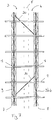
- the structure comprises two elements 7,8 each forming a hollow perforated support of triangular section (for example only) with the support rod at the top, each stud being attached to the two rods by means of clips according to the invention .
- the structure thus obtained forms a sort of ladder that can easily be moved by one or two operators without the risk of falling one or two studs 2.
- the elements 7 and 8 are interconnected by transverse oblique elements 30 (oblique with respect to the axis of the rods 9, 9a) so as to increase the stability of the structure with pre-installed studs (2), in particular when the casting operation of the concrete.
- the structure according to the invention is particularly useful in the realization of concrete lining with expansion joint between adjacent slabs.
- the clip according to the invention can also be used to attach more than one stud to a structure, adapting the size and shape of the curved portion.
Landscapes
- Engineering & Computer Science (AREA)
- Architecture (AREA)
- Civil Engineering (AREA)
- Structural Engineering (AREA)
- Clamps And Clips (AREA)
Priority Applications (1)
| Application Number | Priority Date | Filing Date | Title |
|---|---|---|---|
| EP16020452.5A EP3323937A1 (de) | 2016-11-17 | 2016-11-17 | Befestigungsmittel oder clips für betonplattenbolzen |
Applications Claiming Priority (1)
| Application Number | Priority Date | Filing Date | Title |
|---|---|---|---|
| EP16020452.5A EP3323937A1 (de) | 2016-11-17 | 2016-11-17 | Befestigungsmittel oder clips für betonplattenbolzen |
Publications (1)
| Publication Number | Publication Date |
|---|---|
| EP3323937A1 true EP3323937A1 (de) | 2018-05-23 |
Family
ID=57354063
Family Applications (1)
| Application Number | Title | Priority Date | Filing Date |
|---|---|---|---|
| EP16020452.5A Withdrawn EP3323937A1 (de) | 2016-11-17 | 2016-11-17 | Befestigungsmittel oder clips für betonplattenbolzen |
Country Status (1)
| Country | Link |
|---|---|
| EP (1) | EP3323937A1 (de) |
Cited By (1)
| Publication number | Priority date | Publication date | Assignee | Title |
|---|---|---|---|---|
| WO2020181085A1 (en) * | 2019-03-07 | 2020-09-10 | Illinois Tool Works Inc. | Linking device |
Citations (8)
| Publication number | Priority date | Publication date | Assignee | Title |
|---|---|---|---|---|
| GB431602A (en) * | 1934-04-21 | 1935-07-11 | William Harold Eichelman | Improvements in expansion joints for concrete roads or pavements |
| US5217191A (en) * | 1992-07-21 | 1993-06-08 | Smith Robert L | Pipe hangers or the like |
| US5791816A (en) * | 1996-10-31 | 1998-08-11 | Mccallion; James | Concrete joint restraint system |
| US6092960A (en) | 1998-10-27 | 2000-07-25 | Mccallion; James P. | Concrete joint restraint system |
| US6171016B1 (en) | 1998-10-20 | 2001-01-09 | Concrete Systems, Inc. | Tubular reinforcing dowel system and method |
| US6210070B1 (en) | 1999-04-14 | 2001-04-03 | Ron D. Shaw | Concrete dowel slip tube with clip |
| US20060131465A1 (en) * | 2004-12-22 | 2006-06-22 | Lynch Edward J Jr | Pipe support and method of installation |
| US20110017880A1 (en) * | 2008-01-21 | 2011-01-27 | Osborn Eric C | Lateral seismic brace |
-
2016
- 2016-11-17 EP EP16020452.5A patent/EP3323937A1/de not_active Withdrawn
Patent Citations (8)
| Publication number | Priority date | Publication date | Assignee | Title |
|---|---|---|---|---|
| GB431602A (en) * | 1934-04-21 | 1935-07-11 | William Harold Eichelman | Improvements in expansion joints for concrete roads or pavements |
| US5217191A (en) * | 1992-07-21 | 1993-06-08 | Smith Robert L | Pipe hangers or the like |
| US5791816A (en) * | 1996-10-31 | 1998-08-11 | Mccallion; James | Concrete joint restraint system |
| US6171016B1 (en) | 1998-10-20 | 2001-01-09 | Concrete Systems, Inc. | Tubular reinforcing dowel system and method |
| US6092960A (en) | 1998-10-27 | 2000-07-25 | Mccallion; James P. | Concrete joint restraint system |
| US6210070B1 (en) | 1999-04-14 | 2001-04-03 | Ron D. Shaw | Concrete dowel slip tube with clip |
| US20060131465A1 (en) * | 2004-12-22 | 2006-06-22 | Lynch Edward J Jr | Pipe support and method of installation |
| US20110017880A1 (en) * | 2008-01-21 | 2011-01-27 | Osborn Eric C | Lateral seismic brace |
Cited By (2)
| Publication number | Priority date | Publication date | Assignee | Title |
|---|---|---|---|---|
| WO2020181085A1 (en) * | 2019-03-07 | 2020-09-10 | Illinois Tool Works Inc. | Linking device |
| US11840834B2 (en) | 2019-03-07 | 2023-12-12 | Illinois Tool Works Inc. | Linking device |
Similar Documents
| Publication | Publication Date | Title |
|---|---|---|
| DK2342489T3 (en) | Clamp to attach a pipe to a support structure | |
| EP2183491B1 (de) | Vorrichtung zum anordnen von einem klemmring auf einem teil und automatisch ausgelöstes klemmsystem mit einer solchen vorrichtung | |
| US7905694B2 (en) | Securing assembly | |
| EP2825395B1 (de) | Struktur zur montage einer klammer für eine schreibvorrichtung | |
| WO2009019355A2 (fr) | Perfectionnement au(x) guide(s) installe(s) sur un convoyeur | |
| FR2626749A1 (fr) | Pince a cheveux | |
| EP3323937A1 (de) | Befestigungsmittel oder clips für betonplattenbolzen | |
| EP2456931A1 (de) | Litze mit doppelverriegelung | |
| EP2270290A1 (de) | Befestigungsvorrichtung für Boden | |
| FR2946104A1 (fr) | Dispositif de pince a ecrou, susceptible d'etre place sur le bord d'un support tel qu'un panneau | |
| FR2802585A1 (fr) | Agrafe de fixation pour materiau tendre | |
| EP2811222B1 (de) | Einbauleuchte | |
| FR2505262A1 (fr) | Dispositif permettant de maintenir en liasse des feuilles empilees et perforees | |
| WO2008125164A1 (fr) | Pince à fixation sur tige filetée support de revêtement de plafond | |
| WO2009059673A1 (fr) | Pince à fixation sur élément allongé pour suspente de revêtement de plafond | |
| EP1646792A1 (de) | Profilleiste zur befestigung eines gespannten tuchs | |
| EP1107413B1 (de) | Verfahren zur Montage eines Kabelkanals und Zusammenbau von ihn erzeugenden langgestreckten Kabelkanal-Elementen | |
| EP2463455B1 (de) | Halterungs- und Befestigungsvorrichtung eines Bauzubehörteils, wie eines Dachrinnenbügels, zur Befestigung an der Dachabdeckung | |
| EP0252443B1 (de) | Vorrichtung zum Befestigen auf einem Halterprofil | |
| JP3983752B2 (ja) | 屋根板取付け金具および屋根構造 | |
| FR2710091A1 (fr) | Dispositif de mise en place et de positionnement d'armature dans des coffrages pour béton armé. | |
| EP2520733B1 (de) | Dachrinnenbefestigungssystem, Dach mit dem Dachbefestigungssystem und entsprechende Anwendung | |
| FR2972667A1 (fr) | Outil de pose d'agrafes de fixation et ensemble de fixation comprenant un tel outil | |
| FR2538085A1 (fr) | Dispositif de fixation pour le serpentin en matiere synthetique d'une installation de chauffage par le sol | |
| FR2874040A1 (fr) | Dispositif pour la fixation de panneaux sur une structure support fixe |
Legal Events
| Date | Code | Title | Description |
|---|---|---|---|
| PUAI | Public reference made under article 153(3) epc to a published international application that has entered the european phase |
Free format text: ORIGINAL CODE: 0009012 |
|
| AK | Designated contracting states |
Kind code of ref document: A1 Designated state(s): AL AT BE BG CH CY CZ DE DK EE ES FI FR GB GR HR HU IE IS IT LI LT LU LV MC MK MT NL NO PL PT RO RS SE SI SK SM TR |
|
| AX | Request for extension of the european patent |
Extension state: BA ME |
|
| 17P | Request for examination filed |
Effective date: 20180702 |
|
| RBV | Designated contracting states (corrected) |
Designated state(s): AL AT BE BG CH CY CZ DE DK EE ES FI FR GB GR HR HU IE IS IT LI LT LU LV MC MK MT NL NO PL PT RO RS SE SI SK SM TR |
|
| 17Q | First examination report despatched |
Effective date: 20190603 |
|
| STAA | Information on the status of an ep patent application or granted ep patent |
Free format text: STATUS: THE APPLICATION IS DEEMED TO BE WITHDRAWN |
|
| 18D | Application deemed to be withdrawn |
Effective date: 20191015 |