EP3322916B1 - Getriebe mit zumindest einer exzenterwelle - Google Patents
Getriebe mit zumindest einer exzenterwelle Download PDFInfo
- Publication number
- EP3322916B1 EP3322916B1 EP16730688.5A EP16730688A EP3322916B1 EP 3322916 B1 EP3322916 B1 EP 3322916B1 EP 16730688 A EP16730688 A EP 16730688A EP 3322916 B1 EP3322916 B1 EP 3322916B1
- Authority
- EP
- European Patent Office
- Prior art keywords
- eccentric
- eccentric shaft
- gear
- shaft
- epicyclic wheel
- Prior art date
- Legal status (The legal status is an assumption and is not a legal conclusion. Google has not performed a legal analysis and makes no representation as to the accuracy of the status listed.)
- Active
Links
Images

Classifications
-
- F—MECHANICAL ENGINEERING; LIGHTING; HEATING; WEAPONS; BLASTING
- F16—ENGINEERING ELEMENTS AND UNITS; GENERAL MEASURES FOR PRODUCING AND MAINTAINING EFFECTIVE FUNCTIONING OF MACHINES OR INSTALLATIONS; THERMAL INSULATION IN GENERAL
- F16H—GEARING
- F16H1/00—Toothed gearings for conveying rotary motion
- F16H1/28—Toothed gearings for conveying rotary motion with gears having orbital motion
- F16H1/32—Toothed gearings for conveying rotary motion with gears having orbital motion in which the central axis of the gearing lies inside the periphery of an orbital gear
-
- F—MECHANICAL ENGINEERING; LIGHTING; HEATING; WEAPONS; BLASTING
- F16—ENGINEERING ELEMENTS AND UNITS; GENERAL MEASURES FOR PRODUCING AND MAINTAINING EFFECTIVE FUNCTIONING OF MACHINES OR INSTALLATIONS; THERMAL INSULATION IN GENERAL
- F16D—COUPLINGS FOR TRANSMITTING ROTATION; CLUTCHES; BRAKES
- F16D1/00—Couplings for rigidly connecting two coaxial shafts or other movable machine elements
- F16D1/06—Couplings for rigidly connecting two coaxial shafts or other movable machine elements for attachment of a member on a shaft or on a shaft-end
- F16D1/08—Couplings for rigidly connecting two coaxial shafts or other movable machine elements for attachment of a member on a shaft or on a shaft-end with clamping hub; with hub and longitudinal key
- F16D1/0852—Couplings for rigidly connecting two coaxial shafts or other movable machine elements for attachment of a member on a shaft or on a shaft-end with clamping hub; with hub and longitudinal key with radial clamping between the mating surfaces of the hub and shaft
- F16D1/0858—Couplings for rigidly connecting two coaxial shafts or other movable machine elements for attachment of a member on a shaft or on a shaft-end with clamping hub; with hub and longitudinal key with radial clamping between the mating surfaces of the hub and shaft due to the elasticity of the hub (including shrink fits)
-
- F—MECHANICAL ENGINEERING; LIGHTING; HEATING; WEAPONS; BLASTING
- F16—ENGINEERING ELEMENTS AND UNITS; GENERAL MEASURES FOR PRODUCING AND MAINTAINING EFFECTIVE FUNCTIONING OF MACHINES OR INSTALLATIONS; THERMAL INSULATION IN GENERAL
- F16H—GEARING
- F16H57/00—General details of gearing
- F16H57/0018—Shaft assemblies for gearings
- F16H57/0025—Shaft assemblies for gearings with gearing elements rigidly connected to a shaft, e.g. securing gears or pulleys by specially adapted splines, keys or methods
-
- F—MECHANICAL ENGINEERING; LIGHTING; HEATING; WEAPONS; BLASTING
- F16—ENGINEERING ELEMENTS AND UNITS; GENERAL MEASURES FOR PRODUCING AND MAINTAINING EFFECTIVE FUNCTIONING OF MACHINES OR INSTALLATIONS; THERMAL INSULATION IN GENERAL
- F16D—COUPLINGS FOR TRANSMITTING ROTATION; CLUTCHES; BRAKES
- F16D1/00—Couplings for rigidly connecting two coaxial shafts or other movable machine elements
- F16D1/10—Quick-acting couplings in which the parts are connected by simply bringing them together axially
- F16D2001/102—Quick-acting couplings in which the parts are connected by simply bringing them together axially the torque is transmitted via polygon shaped connections
-
- F—MECHANICAL ENGINEERING; LIGHTING; HEATING; WEAPONS; BLASTING
- F16—ENGINEERING ELEMENTS AND UNITS; GENERAL MEASURES FOR PRODUCING AND MAINTAINING EFFECTIVE FUNCTIONING OF MACHINES OR INSTALLATIONS; THERMAL INSULATION IN GENERAL
- F16H—GEARING
- F16H1/00—Toothed gearings for conveying rotary motion
- F16H1/28—Toothed gearings for conveying rotary motion with gears having orbital motion
- F16H1/32—Toothed gearings for conveying rotary motion with gears having orbital motion in which the central axis of the gearing lies inside the periphery of an orbital gear
- F16H2001/323—Toothed gearings for conveying rotary motion with gears having orbital motion in which the central axis of the gearing lies inside the periphery of an orbital gear comprising eccentric crankshafts driving or driven by a gearing
Definitions
- the invention relates to a transmission with at least one eccentric shaft.
- the object of the invention is therefore to design a gearbox with an eccentric shaft that is easy to manufacture and to enable the transmission of high torques in the smallest possible space.
- the advantage here is that high torque can be transmitted in a small space because the planet wheel is connected to the eccentric shaft via the particularly load-bearing polygon connection.
- the polygonal shaft-hub connection between the planet gear and the eccentric shaft transmits a very high torque, especially when compared to splines according to DIN5480.
- production can be carried out simply and inexpensively, since the machine tool, in particular grinding machine, which can be used to produce the eccentric core regions can also be used to produce the non-circular region. Grinding can thus be carried out without additional clamping and alignment.
- the eccentric core area is a circular cylindrical section which is arranged parallel but spaced apart, in particular therefore not coaxially, to the central axis of the eccentric shaft and / or of the planetary gear.
- the advantage here is that the eccentric core area is arranged eccentrically to the shaft axis of the eccentric shaft. Grinding can thus be carried out by the same machine with which the non-circular area can also be machined.
- the non-circular shaped section is axially spaced from the eccentric core area.
- the non-circular shaped section is composed of hypotrochoidal sections.
- the planetary wheel has a recess shaped in accordance with the non-circular section, so that the planetary gear is connected to the eccentric shaft in a rotationally fixed and play-free manner by means of the non-circular section.
- the advantage here is that the planetary gear is plugged onto the eccentric shaft, in particular thermally shrunk, and thus a play-free, rotationally fixed connection is made possible.
- the external toothing of the disk engages with a ring gear that forms the housing.
- the advantage here is that no rollers or cams are required, but involute-toothed disks can be used. This enables an exact and precise rolling of the disc on the circumference of the ring gear.
- the external toothing is designed as an involute toothing.
- the advantage here is that simple and precise production can be carried out.
- the eccentric shaft has a second eccentric core area which is axially spaced from the first eccentric core area and has an offset in the circumferential direction of 180 °, in particular with the eccentric core regions being of the same shape.
- the eccentric shaft is rotatably mounted in an output shaft of the transmission, the axis of the eccentric shaft being arranged parallel and at a distance from the axis of the output shaft.
- the output shaft is rotatably mounted in the ring gear by means of at least one angular bearing.
- the planet gear meshes with a sun gear toothing which is arranged coaxially with the output shaft. wherein the planet gear, the sun gear and at least one other planet gear form a spur gear stage.
- the advantage here is that an additional gear ratio is available when the torque is split from the sun to several planet gears.
- the sun gear toothing is arranged in a rotationally fixed and coaxial manner to a gearwheel which is in engagement with a toothing part, in particular pinion gear, which is driven directly by an electric motor or via a clutch.
- a gearwheel which is in engagement with a toothing part, in particular pinion gear, which is driven directly by an electric motor or via a clutch.
- the eccentric shaft has a second eccentric core area, on which a second externally toothed disk of the transmission is rotatably arranged, wherein the external toothing of the second disk is in engagement with the internal toothing of the ring gear.
- the input shaft drives a pinion 3 which is in mesh with a gear 2.
- the gear 2 is rotatably connected to a sun gear shaft 1, which has a sun gear toothing or is rotatably connected to a sun gear.
- the eccentric shaft 11 has a polygonal axial section.
- the polygon is preferably shaped according to a hypotrochoid.
- the planet gear 4 has a correspondingly shaped inner polygonal recess and is plugged onto the eccentric shaft 11, particularly preferably shrink-wrapped thermally.
- a rotationally fixed, play-free connection between the respective planet gear 4 and the respective eccentric shaft 11 is thus carried out in a simple manner.
- the polygonal outer contour of the eccentric shaft 11 can be produced without any special effort, since the eccentric shaft has two axial sections spaced from the axial section, each of which is shaped as an eccentric core region 31, 32.
- the eccentric shaft has two axial sections spaced from the axial section, each of which is shaped as an eccentric core region 31, 32.
- the eccentric core regions 11 are spaced axially from one another or at least at most touching and have an offset in the circumferential direction of 180 °, the eccentric core regions 11 being otherwise identical.
- the eccentric core regions 31 and 32 and the polygonal section can thus be produced with one and the same machine tool, that is to say in a single clamping. There is no special additional manufacturing effort for the polygonal outer contour.
- a bearing 5 is plugged onto the first eccentric core region 31 and is received in a borehole arranged centrally on a first externally toothed disk 7.
- the external toothing of the disc 7 is designed as an involute toothing and is in engagement with the inner toothing of a ring gear 9 connected or forming the housing.
- the internal toothing of the ring gear 9 is also designed as an involute toothing ,
- a bearing 15 is plugged onto the second eccentric core area 32 and is received in a borehole arranged centrally on a second externally toothed disk 8.
- the second disc 8 is rotatably supported on the second eccentric core area 32.
- the external toothing of the second disc 8 is designed as an involute toothing and is also in engagement with the internal toothing of the ring gear 9.
- the internal toothing of the ring gear 9 extends over such a wide axial area that it covers the two axial areas covered by the external teeth of the first and second disks 7, 8.
- the eccentric shafts 11 are rotatably supported in the output shaft 12, the bearing receptacles of the bearings 14, 16 supporting the eccentric shafts 11 being radially spaced from the central axis of the output shaft 12.
- the output shaft 12 is mounted in the ring gear 9 by means of angular bearings 10.
Description
- Die Erfindung betrifft ein Getriebe mit zumindest einer Exzenterwelle.
- Es ist allgemein bekannt, dass die Herstellung von Exzenterwellen eines Getriebes mit einer Rundschleifmaschine ausführbar ist.
- Aus der
EP1225356 A1 ist eine unrunde Welle-Nabe-Verbindung bekannt. - Aus der
WO 2013/065 261 A1 ist als nächstliegender Stand der Technik ein Getriebe bekannt. - Aus der
CN 201 027 913 Y ist ein Planetengetriebe bekannt. - Aus der
CN 103 742 610 A ist ein Getriebe bekannt. - Aus der
US 8 663 049 B1 ist ein Zyklogetriebe bekannt. - Aus der
US 4 025 210 A ist eine unrunde Welle bekannt. - Aus der
JP 2004 270 846 A - Der Erfindung liegt daher die Aufgabe zugrunde, ein Getriebe mit Exzenterwelle einfach herstellbar auszubilden und die Übertragung hoher Drehmomente in einem möglichst geringen Raumberiech zu ermöglichen.
- Erfindungsgemäß wird die Aufgabe bei dem Getriebe nach den in Anspruch 1 angegebenen Merkmalen gelöst.
- Von Vorteil ist dabei, dass ein hohes Drehmoment auf kleinem Raumbereich übertragbar ist, weil das Umlaufrad über die besonders tragfähige Polygonverbindung mit der Exzenterwelle verbunden ist. Insbesondere im Vergleich zu einer Steckverzahnung nach DIN5480 überträgt die polygonale Welle-Nabe-Verbindung zwischen Umlaufrad und Exzenterwelle ein sehr hohes Drehmoment. Außerdem ist Herstellung einfach und kostengünstig ausführbar, da die zum Herstellen der Exzenterkernbereiche einsetzbare Werkzeugmaschine, insbesondere Schleifmaschine, auch zum Herstellen des unrunden Bereichs einsetzbar ist. Somit ist eine Schleifbearbeitung ohne zusätzliche Aufspannung und Ausrichtung ausführbar.
- Erfindungsgemäß ist der Exzenterkernbereich ein kreiszylindrischer Abschnitt, der parallel aber beabstandet, insbesondere also nicht koaxial, zur Mittenachse der Exzenterwelle und/oder des Umlaufrades angeordnet ist. Von Vorteil ist dabei, dass der Exzenterkernbereich außermittig zur Wellenachse der Exzenterwelle angeordnet ist. Somit ist die Schleifbearbeitung durch dieselbe Maschine ausführbar, mit welcher auch der unrunde Bereich bearbeitbar ist.
- Erfindungsgemäß ist der unrund geformte Abschnitt axial beabstandet vom Exzenterkernbereich. Von Vorteil ist dabei, dass zur Bearbeitung der Bereiche nur eine axiale Verschiebung notwendig ist.
- Erfindungsgemäß ist der unrund geformte Abschnitt aus hypotrochoidalen Abschnitten zusammengesetzt. Von Vorteil ist dabei, dass eines besonders tragfähige Welle-Nabe-Verbindung wählbar ist.
- Erfindungsgemäß weist das Umlaufrad eine entsprechend dem unrund geformten Abschnitt geformte Ausnehmung auf,
so dass das Umlaufrad drehfest und spielfrei mittels des unrunden Abschnittes mit der Exzenterwelle verbunden ist. Von Vorteil ist dabei, dass das Umlaufrad aufgesteckt ist auf die Exzenterwelle, insbesondere thermisch aufgeschrumpft, und somit einen spielfreie drehfeste Verbindung ermöglicht ist. - Erfindungsgemäß ist die Außenverzahnung der Scheibe mit einem Hohlrad, das gehäusebildend ist, im Eingriff. Von Vorteil ist dabei, dass keine Rollen oder Kurvenscheiben benötigt werden sondern evolventenverzahnte Scheiben verwendbar sind. Somit ist ein exaktes und präzises Abrollen der Scheibe am Umfang des Hohlrades ermöglicht.
- Erfindungsgemäß ist die Außenverzahnung als Evolventenverzahnung ausgeführt. Von Vorteil ist dabei, dass eine einfache und präzise Herstellung ausführbar ist.
- Bei einer vorteilhaften Ausgestaltung weist die Exzenterwelle einen zweiten Exzenterkernbereich auf, der axial beabstandet ist vom ersten Exzenterkernbereich und einen Versatz in Umfangsrichtung von 180° aufweist,
insbesondere wobei die Exzenterkernbereiche gleichartig geformt ausgeführt sind. Von Vorteil ist dabei, dass eine ausgewuchtete Bewegung ermöglicht ist. - Erfindungsgemäß ist die Exzenterwelle drehbar gelagert in einer Abtriebswelle des Getriebes aufgenommen, wobei die Achse der Exzenterwelle parallel und beabstandet zur Achse der Abtriebswelle angeordnet ist. Von Vorteil ist dabei, dass eine Abführung des Drehmoments an die Abtriebswelle in einfacher Weise ermöglicht ist.
- Erfindungsgemäß ist die Abtriebswelle mittels zumindest eines Schräglagers in dem Hohlrad drehbar gelagert. Von Vorteil ist dabei, dass eine stabile Ausführung ermöglicht ist.
- Erfindungsgemäß ist das Umlaufrad mit einer Sonnenradverzahnung im Eingriff, die koaxial zur Abtriebswelle angeordnet ist,
wobei das Umlaufrad, die Sonnenradverzahnung und mindestens ein weiteres Umlaufrad eine Stirnradverteilgetriebestufe bilden. Von Vorteil ist dabei, dass eine zusätzliche Übersetzungsstufe vorhanden ist bei der Aufteilung des Drehmoments von der Sonne an mehrere Umlaufräder. - Erfindungsgemäß ist die Sonnenradverzahnung drehfest und koaxial zu einem Zahnrad angeordnet, das im Eingriff mit einem von einem Elektromotor direkt oder über eine Kupplung angetriebenen Verzahnungsteil, insbesondere Ritzel, ist. Von Vorteil ist dabei, dass eine Vorstufe mit einer geeigneten Übersetzung vorgeordnet ist.
- Bei einer vorteilhaften Ausgestaltung weist die Exzenterwelle einen zweiten Exzenterkernbereich auf, auf dem eine zweite außenverzahnte Scheibe des Getriebes drehbar gelagert angeordnet ist,
wobei die Außenverzahnung der zweiten Scheibe mit der Innenverzahnung des Hohlrades im Eingriff ist. Von Vorteil ist dabei, dass eine ausgewuchtete Bewegung ermöglicht ist. - Die Erfindung wird nun anhand von Abbildungen näher erläutert:
- In der
Figur 1 ist ein Querschnitt durch ein erfindungsgemäßes Getriebe mit Exzenterwellen 11 gezeigt. - In der
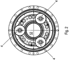
Figur 2 ist ein zugehöriger Längsschnitt gezeigt. - In der
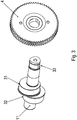
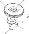
Figur 3 ist eine Exzenterwelle 11 und ein mit ihr verbundenes Planetenrad 4 in explodierter Darstellung gezeigt. - In der
Figur 4 ist die zurFigur 3 gehörige nicht explodierte Darstellung gezeigt. - Wie in den Figuren gezeigt, treibt die eintreibende Welle ein Ritzel 3 an, das mit einem Zahnrad 2 im Eingriff ist.
- Das Zahnrad 2 ist mit einer Sonnenradwelle 1 drehfest verbunden, die eine Sonnenradverzahnung aufweist oder mit einem Sonnenrad drehfest verbunden ist.
- Mit dieser Sonnenradverzahnung sind drei Planetenräder 4 im Eingriff, welche jeweils drehfest mit einer Exzenterwelle 11 verbunden sind. Somit bilden die Sonnenradverzahnung mit den Planetenrädern 4 eine Stirnradverteilgetriebestufe.
- Zur drehfesten Verbindung des jeweiligen Planetenrads 4 mit der jeweiligen Exzenterwelle 11 weist die Exzenterwelle 11 einen polygonal geformten axialen Abschnitt auf. Dabei ist das Polygon vorzugsweise gemäß einer Hypotrochoide geformt. Das Planetenrad 4 weist eine entsprechend geformte innenpolygonale Ausnehmung auf und ist aufgesteckt, insbesondere vorzugsweise thermisch aufgeschrumpft, auf die Exzenterwelle 11. Somit ist eine drehfeste spielfreie Verbindung zwischen jeweiligem Planetenrad 4 und jeweiliger Exzenterwelle 11 in einfacher Weise ausgeführt.
- Die polygonale Außenkontur der Exzenterwelle 11 ist ohne besonderen Aufwand herstellbar, da die Exzenterwelle zwei von dem axialen Abschnitt beabstandete axiale Abschnitte aufweist, die jeweils als Exzenterkernbereich 31, 32 geformt sind. Hierzu weist jeder Exzenterkernbereich zwar eine kreiszylindrische Außenfläche auf; dabei ist aber die Zylinderachse beabstandet von der Mittelachse der Exzenterwelle 11, wobei die Zylinderachse parallel zur Mittelachse ausgerichtet ist.
- Die Exzenterkernbereiche 11 sind axial voneinander beabstandet oder zumindest höchstens berührend angeordnet und weisen einen Versatz in Umfangsrichtung von 180° auf, wobei die Exzenterkernbereiche 11 ansonsten gleichartig ausgeführt sind.
- Somit sind die Exzenterkernbereiche 31 und 32 sowie der polygonale Abschnitt mit ein und derselben Werkzeugmaschine, also in einer einzigen Aufspannung, herstellbar. Für die polygonale Außenkontur ergibt sich also kein besonderer Zusatzherstellungsaufwand.
- Auf den ersten Exzenterkernbereich 31 ist ein Lager 5 aufgesteckt, das in einem mittig an einer ersten außenverzahnten Scheibe 7 angeordneten Bohrloch aufgenommen ist. Somit ist die erste Scheibe 7 drehbar gelagert auf dem Exzenterkernbereich 31. Die Außenverzahnung der Scheibe 7 ist als Evolventenverzahnung ausgeführt und ist im Eingriff mit der Innenverzahnung eines mit dem Gehäuse verbundenen oder gehäusebildenden Hohlrades 9. Dabei ist auch die Innenverzahnung des Hohlrades 9 als Evolventenverzahnung ausgeführt.
- Auf den zweiten Exzenterkernbereich 32 ist ein Lager 15 aufgesteckt, das in einem mittig an einer zweiten außenverzahnten Scheibe 8 angeordneten Bohrloch aufgenommen ist. Somit ist die zweite Scheibe 8 drehbar gelagert auf dem zweiten Exzenterkernbereich 32. Die Außenverzahnung der zweiten Scheibe 8 ist als Evolventenverzahnung ausgeführt und ist ebenfalls im Eingriff mit der Innenverzahnung des Hohlrades 9.
- Die Innenverzahnung des Hohlrades 9 erstreckt sich über einen derart weiten axialen Bereich, dass dieser die beiden von den Außenverzahnungen der ersten und der zweiten Scheibe 7, 8 überdeckten axialen Bereiche überdeckt.
- Die Exzenterwellen 11 sind drehbar gelagert in der Abtriebswelle 12, wobei die Lageraufnahmen der die Exzenterwellen 11 lagernden Lager 14, 16 radial beabstandet sind von der Mittelachse der Abtriebswelle 12.
- Die Abtriebswelle 12 ist mittels Schräglager 10 im Hohlrad 9 gelagert.
-
- 1
- Sonnenradwelle
- 2
- Zahnrad
- 3
- Ritzel
- 4
- Planetenrad
- 5
- Lager
- 6
- Schräglager
- 7
- erste außenverzahnte Scheibe
- 8
- zweite außenverzahnte Scheibe
- 9
- Hohlrad
- 10
- Schräglager
- 11
- Exzenterwelle
- 12
- Abtriebswelle
- 13
- Lager
- 30
- polygonaler Abschnitt der Exzenterwelle 11
- 31
- erster Exzenterkernbereich
- 32
- zweiter Exzenterkernbereich
Claims (3)
- Getriebe mit zumindest einer Exzenterwelle (11), zumindest einer außenverzahnten Scheibe (7, 8) und zumindest einem Umlaufrad, insbesondere Planetenrad (4),
wobei die Exzenterwelle (11) einen Exzenterkernbereich (31, 32) aufweist, auf dem die außenverzahnte Scheibe (7, 8) drehbar gelagert angeordnet ist, insbesondere mittels eines Lagers (5, 15),
wobei die Exzenterwelle (11) einen unrund geformten Abschnitt (30) aufweist, an welchem das Umlaufrad drehfest mit der Exzenterwelle (11) verbunden ist,
wobei der Exzenterkernbereich (31, 32) ein kreiszylindrischer Abschnitt ist, der parallel aber beabstandet, insbesondere also nicht koaxial, zur Mittenachse der Exzenterwelle (11) und/oder des Umlaufrades angeordnet ist,
wobei der unrund geformte Abschnitt axial beabstandet ist vom Exzenterkernbereich (31, 32), wobei die Exzenterwelle (11) drehbar gelagert in einer Abtriebswelle (12) des Getriebes aufgenommen ist, wobei die Achse der Exzenterwelle (11) parallel und beabstandet zur Achse der Abtriebswelle (12) angeordnet ist,
wobei die Abtriebswelle (12) mittels zumindest eines Schräglagers (6, 10) in einem Hohlrad (9) drehbar gelagert ist,
wobei das Umlaufrad mit einer Sonnenradverzahnung im Eingriff ist, die koaxial zur Abtriebswelle (12) angeordnet ist,
wobei das Umlaufrad, die Sonnenradverzahnung und mindestens ein weiteres Umlaufrad eine Stirnradverteilgetriebestufe bilden,
wobei das Umlaufrad eine entsprechend dem unrund geformten Abschnitt geformte Ausnehmung aufweist, so dass das Umlaufrad drehfest und spielfrei mittels des unrund geformten Abschnittes mit der Exzenterwelle (11) verbunden ist,
wobei die Außenverzahnung der Scheibe (7, 8) mit dem Hohlrad (9), das gehäusebildend ist, im Eingriff ist,
dadurch gekennzeichnet, dass die Außenverzahnung der Scheibe (7, 8) als Evolventenverzahnung ausgeführt ist, wobei der unrund geformte Abschnitt (30) aus hypotrochoidalen Abschnitten zusammengesetzt ist, wobei die Sonnenradverzahnung drehfest und koaxial zu einem Zahnrad (2) angeordnet ist, das im Eingriff mit einem von einem Elektromotor direkt oder über eine Kupplung angetriebenen Verzahnungsteil, insbesondere Ritzel (3), ist. - Getriebe nach Anspruch 1,
dadurch gekennzeichnet, dass
die Exzenterwelle (11) einen zweiten Exzenterkernbereich (31, 32) aufweist, der axial beabstandet ist vom ersten Exzenterkernbereich (31, 32) und einen Versatz in Umfangsrichtung von 180° aufweist,
insbesondere wobei die Exzenterkernbereiche (31, 32) gleichartig geformt ausgeführt sind. - Getriebe nach mindestens einem der vorangegangenen Ansprüche,
dadurch gekennzeichnet, dass
die Exzenterwelle (11) einen bzw. den zweiten Exzenterkernbereich (31, 32) aufweist, auf dem eine zweite außenverzahnte Scheibe (7, 8) des Getriebes drehbar gelagert angeordnet ist,
wobei die Außenverzahnung der zweiten Scheibe (7, 8) mit der Innenverzahnung des Hohlrades (9) im Eingriff ist.
Applications Claiming Priority (3)
| Application Number | Priority Date | Filing Date | Title |
|---|---|---|---|
| DE102015008855 | 2015-07-14 | ||
| DE102015011074.8A DE102015011074B4 (de) | 2015-07-14 | 2015-08-27 | Getriebe mit zumindest einer Exzenterwelle |
| PCT/EP2016/000995 WO2017008874A1 (de) | 2015-07-14 | 2016-06-15 | Getriebe mit zumindest einer exzenterwelle |
Publications (2)
| Publication Number | Publication Date |
|---|---|
| EP3322916A1 EP3322916A1 (de) | 2018-05-23 |
| EP3322916B1 true EP3322916B1 (de) | 2020-02-05 |
Family
ID=57629861
Family Applications (1)
| Application Number | Title | Priority Date | Filing Date |
|---|---|---|---|
| EP16730688.5A Active EP3322916B1 (de) | 2015-07-14 | 2016-06-15 | Getriebe mit zumindest einer exzenterwelle |
Country Status (3)
| Country | Link |
|---|---|
| EP (1) | EP3322916B1 (de) |
| DE (1) | DE102015011074B4 (de) |
| WO (1) | WO2017008874A1 (de) |
Families Citing this family (3)
| Publication number | Priority date | Publication date | Assignee | Title |
|---|---|---|---|---|
| DE102017126737A1 (de) | 2017-11-14 | 2019-05-16 | Kimex Group s.r.o. | Getriebe |
| EP3483473A1 (de) | 2017-11-14 | 2019-05-15 | Kimex Group s.r.o. | Getriebe |
| CN112833141B (zh) * | 2020-08-26 | 2023-05-12 | 辽宁石油化工大学 | 一种椭圆行星轮系式弹齿滚筒花生捡拾装置 |
Family Cites Families (9)
| Publication number | Priority date | Publication date | Assignee | Title |
|---|---|---|---|---|
| US4025210A (en) * | 1975-07-10 | 1977-05-24 | Pontiac Furniture Industries, Inc. | Shaft assembly |
| DE50103741D1 (de) | 2001-01-19 | 2004-10-28 | Visteon Global Tech Inc | Welle-Nabe-Verbindung |
| JP4755357B2 (ja) | 2001-04-18 | 2011-08-24 | ナブテスコ株式会社 | 減速機 |
| JP2004270846A (ja) * | 2003-03-10 | 2004-09-30 | Ts Corporation | 偏心揺動型減速機、その偏心揺動型減速機を備えた回転駆動装置及びその回転駆動装置備えた容器 |
| CN201027913Y (zh) * | 2006-08-11 | 2008-02-27 | 北京华能通达能源科技有限公司 | Xb行摆微齿差传动器 |
| JP2013096550A (ja) | 2011-11-04 | 2013-05-20 | Nabtesco Corp | 歯車伝動装置 |
| US8663049B1 (en) | 2012-11-28 | 2014-03-04 | Tsun-Tien Yao | Speed reducer |
| JP2015021554A (ja) | 2013-07-18 | 2015-02-02 | ナブテスコ株式会社 | 偏心揺動型歯車装置 |
| CN103742610A (zh) * | 2013-12-23 | 2014-04-23 | 陕西秦川机械发展股份有限公司 | 一种2k-v型减速器 |
-
2015
- 2015-08-27 DE DE102015011074.8A patent/DE102015011074B4/de active Active
-
2016
- 2016-06-15 WO PCT/EP2016/000995 patent/WO2017008874A1/de active Application Filing
- 2016-06-15 EP EP16730688.5A patent/EP3322916B1/de active Active
Non-Patent Citations (1)
| Title |
|---|
| None * |
Also Published As
| Publication number | Publication date |
|---|---|
| WO2017008874A1 (de) | 2017-01-19 |
| DE102015011074A1 (de) | 2017-01-19 |
| DE102015011074B4 (de) | 2022-09-29 |
| EP3322916A1 (de) | 2018-05-23 |
Similar Documents
| Publication | Publication Date | Title |
|---|---|---|
| EP3371482B1 (de) | Getriebe mit anlaufscheibe | |
| EP3322908B1 (de) | Getriebe mit anlaufscheibe zur axialen sicherung von wälzkörpern eines lagers | |
| EP2376810B1 (de) | Gussteil, planetenträger, hohlwelle und planetengetriebe | |
| EP2999895B1 (de) | Welle-nabe-verbindung und getriebemotor | |
| DE102007015289B4 (de) | Oszillierendes innen eingreifendes Planetenradreduktionsgetriebe | |
| EP3001020A1 (de) | Flugtriebwerk mit einer kompressoreinrichtung | |
| EP3322916B1 (de) | Getriebe mit zumindest einer exzenterwelle | |
| DE102012210169A1 (de) | Exzentergetriebe | |
| EP3184856B1 (de) | Planetengetriebevorrichtung und strahltriebwerk mit einer planetengetriebevorrichtung | |
| WO2016004933A1 (de) | Kreisschiebeplanetenradgetriebe | |
| WO2016198146A1 (de) | Getriebe mit einem gehäuse und einer planetengetriebestufe | |
| DE102022002656A1 (de) | Getriebe mit einer ersten Planetengetriebestufe | |
| EP3259492A1 (de) | Getriebeanordnung | |
| EP2381132B1 (de) | Getriebe | |
| EP3809015B1 (de) | Wellgetriebe mit zahnriemen | |
| WO2015083040A2 (de) | Planeten-schraubenrad-getriebe | |
| AT525577B1 (de) | Planetengetriebe | |
| EP3179138B1 (de) | Vorrichtung und verfahren zur verbindung zweier rotierender maschinenteile | |
| WO2023078960A1 (de) | Getriebe mit getriebestufe, aufweisend ein zentralrad, umlaufräder und ein planverzahntes rad | |
| WO2023104233A1 (de) | Planetengetriebe mit anlaufscheibe für zwei hohlräder, axiale hohlradabstützung, anlaufscheibe für ein hohlrad und elektrofahrzeugantriebsstrang mit axial abgestützten hohlrädern | |
| WO2023030677A1 (de) | Getriebe mit einer zweiten planetengetriebestufe | |
| EP4217626A1 (de) | Antrieb, aufweisend ein von einem elektromotor angetriebenes getriebe | |
| EP2565497A1 (de) | Planetengetriebe für eine Windkraftanlage oder eine Mühlenantriebssystem | |
| DE102014202281A1 (de) | Ölpumpenantrieb | |
| DE102011118481A1 (de) | Differentialanordnung, insbesondere Kronenraddifferential |
Legal Events
| Date | Code | Title | Description |
|---|---|---|---|
| STAA | Information on the status of an ep patent application or granted ep patent |
Free format text: STATUS: THE INTERNATIONAL PUBLICATION HAS BEEN MADE |
|
| PUAI | Public reference made under article 153(3) epc to a published international application that has entered the european phase |
Free format text: ORIGINAL CODE: 0009012 |
|
| STAA | Information on the status of an ep patent application or granted ep patent |
Free format text: STATUS: REQUEST FOR EXAMINATION WAS MADE |
|
| 17P | Request for examination filed |
Effective date: 20180214 |
|
| AK | Designated contracting states |
Kind code of ref document: A1 Designated state(s): AL AT BE BG CH CY CZ DE DK EE ES FI FR GB GR HR HU IE IS IT LI LT LU LV MC MK MT NL NO PL PT RO RS SE SI SK SM TR |
|
| AX | Request for extension of the european patent |
Extension state: BA ME |
|
| DAV | Request for validation of the european patent (deleted) | ||
| DAX | Request for extension of the european patent (deleted) | ||
| STAA | Information on the status of an ep patent application or granted ep patent |
Free format text: STATUS: EXAMINATION IS IN PROGRESS |
|
| 17Q | First examination report despatched |
Effective date: 20190220 |
|
| GRAP | Despatch of communication of intention to grant a patent |
Free format text: ORIGINAL CODE: EPIDOSNIGR1 |
|
| STAA | Information on the status of an ep patent application or granted ep patent |
Free format text: STATUS: GRANT OF PATENT IS INTENDED |
|
| RIC1 | Information provided on ipc code assigned before grant |
Ipc: F16D 1/10 20060101ALN20190816BHEP Ipc: F16D 1/08 20060101ALI20190816BHEP Ipc: F16H 1/32 20060101AFI20190816BHEP Ipc: F16H 57/00 20120101ALI20190816BHEP |
|
| INTG | Intention to grant announced |
Effective date: 20190916 |
|
| GRAS | Grant fee paid |
Free format text: ORIGINAL CODE: EPIDOSNIGR3 |
|
| GRAA | (expected) grant |
Free format text: ORIGINAL CODE: 0009210 |
|
| STAA | Information on the status of an ep patent application or granted ep patent |
Free format text: STATUS: THE PATENT HAS BEEN GRANTED |
|
| AK | Designated contracting states |
Kind code of ref document: B1 Designated state(s): AL AT BE BG CH CY CZ DE DK EE ES FI FR GB GR HR HU IE IS IT LI LT LU LV MC MK MT NL NO PL PT RO RS SE SI SK SM TR |
|
| REG | Reference to a national code |
Ref country code: GB Ref legal event code: FG4D Free format text: NOT ENGLISH |
|
| REG | Reference to a national code |
Ref country code: AT Ref legal event code: REF Ref document number: 1230136 Country of ref document: AT Kind code of ref document: T Effective date: 20200215 |
|
| REG | Reference to a national code |
Ref country code: DE Ref legal event code: R096 Ref document number: 502016008630 Country of ref document: DE |
|
| REG | Reference to a national code |
Ref country code: IE Ref legal event code: FG4D Free format text: LANGUAGE OF EP DOCUMENT: GERMAN |
|
| REG | Reference to a national code |
Ref country code: CH Ref legal event code: EP |
|
| REG | Reference to a national code |
Ref country code: NL Ref legal event code: MP Effective date: 20200205 |
|
| PG25 | Lapsed in a contracting state [announced via postgrant information from national office to epo] |
Ref country code: FI Free format text: LAPSE BECAUSE OF FAILURE TO SUBMIT A TRANSLATION OF THE DESCRIPTION OR TO PAY THE FEE WITHIN THE PRESCRIBED TIME-LIMIT Effective date: 20200205 Ref country code: RS Free format text: LAPSE BECAUSE OF FAILURE TO SUBMIT A TRANSLATION OF THE DESCRIPTION OR TO PAY THE FEE WITHIN THE PRESCRIBED TIME-LIMIT Effective date: 20200205 Ref country code: PT Free format text: LAPSE BECAUSE OF FAILURE TO SUBMIT A TRANSLATION OF THE DESCRIPTION OR TO PAY THE FEE WITHIN THE PRESCRIBED TIME-LIMIT Effective date: 20200628 Ref country code: NO Free format text: LAPSE BECAUSE OF FAILURE TO SUBMIT A TRANSLATION OF THE DESCRIPTION OR TO PAY THE FEE WITHIN THE PRESCRIBED TIME-LIMIT Effective date: 20200505 |
|
| REG | Reference to a national code |
Ref country code: LT Ref legal event code: MG4D |
|
| PG25 | Lapsed in a contracting state [announced via postgrant information from national office to epo] |
Ref country code: SE Free format text: LAPSE BECAUSE OF FAILURE TO SUBMIT A TRANSLATION OF THE DESCRIPTION OR TO PAY THE FEE WITHIN THE PRESCRIBED TIME-LIMIT Effective date: 20200205 Ref country code: LV Free format text: LAPSE BECAUSE OF FAILURE TO SUBMIT A TRANSLATION OF THE DESCRIPTION OR TO PAY THE FEE WITHIN THE PRESCRIBED TIME-LIMIT Effective date: 20200205 Ref country code: BG Free format text: LAPSE BECAUSE OF FAILURE TO SUBMIT A TRANSLATION OF THE DESCRIPTION OR TO PAY THE FEE WITHIN THE PRESCRIBED TIME-LIMIT Effective date: 20200505 Ref country code: GR Free format text: LAPSE BECAUSE OF FAILURE TO SUBMIT A TRANSLATION OF THE DESCRIPTION OR TO PAY THE FEE WITHIN THE PRESCRIBED TIME-LIMIT Effective date: 20200506 Ref country code: IS Free format text: LAPSE BECAUSE OF FAILURE TO SUBMIT A TRANSLATION OF THE DESCRIPTION OR TO PAY THE FEE WITHIN THE PRESCRIBED TIME-LIMIT Effective date: 20200605 Ref country code: HR Free format text: LAPSE BECAUSE OF FAILURE TO SUBMIT A TRANSLATION OF THE DESCRIPTION OR TO PAY THE FEE WITHIN THE PRESCRIBED TIME-LIMIT Effective date: 20200205 |
|
| PG25 | Lapsed in a contracting state [announced via postgrant information from national office to epo] |
Ref country code: NL Free format text: LAPSE BECAUSE OF FAILURE TO SUBMIT A TRANSLATION OF THE DESCRIPTION OR TO PAY THE FEE WITHIN THE PRESCRIBED TIME-LIMIT Effective date: 20200205 |
|
| PG25 | Lapsed in a contracting state [announced via postgrant information from national office to epo] |
Ref country code: SM Free format text: LAPSE BECAUSE OF FAILURE TO SUBMIT A TRANSLATION OF THE DESCRIPTION OR TO PAY THE FEE WITHIN THE PRESCRIBED TIME-LIMIT Effective date: 20200205 Ref country code: SK Free format text: LAPSE BECAUSE OF FAILURE TO SUBMIT A TRANSLATION OF THE DESCRIPTION OR TO PAY THE FEE WITHIN THE PRESCRIBED TIME-LIMIT Effective date: 20200205 Ref country code: ES Free format text: LAPSE BECAUSE OF FAILURE TO SUBMIT A TRANSLATION OF THE DESCRIPTION OR TO PAY THE FEE WITHIN THE PRESCRIBED TIME-LIMIT Effective date: 20200205 Ref country code: DK Free format text: LAPSE BECAUSE OF FAILURE TO SUBMIT A TRANSLATION OF THE DESCRIPTION OR TO PAY THE FEE WITHIN THE PRESCRIBED TIME-LIMIT Effective date: 20200205 Ref country code: CZ Free format text: LAPSE BECAUSE OF FAILURE TO SUBMIT A TRANSLATION OF THE DESCRIPTION OR TO PAY THE FEE WITHIN THE PRESCRIBED TIME-LIMIT Effective date: 20200205 Ref country code: EE Free format text: LAPSE BECAUSE OF FAILURE TO SUBMIT A TRANSLATION OF THE DESCRIPTION OR TO PAY THE FEE WITHIN THE PRESCRIBED TIME-LIMIT Effective date: 20200205 Ref country code: LT Free format text: LAPSE BECAUSE OF FAILURE TO SUBMIT A TRANSLATION OF THE DESCRIPTION OR TO PAY THE FEE WITHIN THE PRESCRIBED TIME-LIMIT Effective date: 20200205 Ref country code: RO Free format text: LAPSE BECAUSE OF FAILURE TO SUBMIT A TRANSLATION OF THE DESCRIPTION OR TO PAY THE FEE WITHIN THE PRESCRIBED TIME-LIMIT Effective date: 20200205 |
|
| REG | Reference to a national code |
Ref country code: DE Ref legal event code: R097 Ref document number: 502016008630 Country of ref document: DE |
|
| PLBE | No opposition filed within time limit |
Free format text: ORIGINAL CODE: 0009261 |
|
| STAA | Information on the status of an ep patent application or granted ep patent |
Free format text: STATUS: NO OPPOSITION FILED WITHIN TIME LIMIT |
|
| 26N | No opposition filed |
Effective date: 20201106 |
|
| PG25 | Lapsed in a contracting state [announced via postgrant information from national office to epo] |
Ref country code: MC Free format text: LAPSE BECAUSE OF FAILURE TO SUBMIT A TRANSLATION OF THE DESCRIPTION OR TO PAY THE FEE WITHIN THE PRESCRIBED TIME-LIMIT Effective date: 20200205 Ref country code: IT Free format text: LAPSE BECAUSE OF FAILURE TO SUBMIT A TRANSLATION OF THE DESCRIPTION OR TO PAY THE FEE WITHIN THE PRESCRIBED TIME-LIMIT Effective date: 20200205 |
|
| REG | Reference to a national code |
Ref country code: CH Ref legal event code: PL |
|
| PG25 | Lapsed in a contracting state [announced via postgrant information from national office to epo] |
Ref country code: PL Free format text: LAPSE BECAUSE OF FAILURE TO SUBMIT A TRANSLATION OF THE DESCRIPTION OR TO PAY THE FEE WITHIN THE PRESCRIBED TIME-LIMIT Effective date: 20200205 Ref country code: SI Free format text: LAPSE BECAUSE OF FAILURE TO SUBMIT A TRANSLATION OF THE DESCRIPTION OR TO PAY THE FEE WITHIN THE PRESCRIBED TIME-LIMIT Effective date: 20200205 |
|
| PG25 | Lapsed in a contracting state [announced via postgrant information from national office to epo] |
Ref country code: LU Free format text: LAPSE BECAUSE OF NON-PAYMENT OF DUE FEES Effective date: 20200615 |
|
| REG | Reference to a national code |
Ref country code: BE Ref legal event code: MM Effective date: 20200630 |
|
| PG25 | Lapsed in a contracting state [announced via postgrant information from national office to epo] |
Ref country code: LI Free format text: LAPSE BECAUSE OF NON-PAYMENT OF DUE FEES Effective date: 20200630 Ref country code: CH Free format text: LAPSE BECAUSE OF NON-PAYMENT OF DUE FEES Effective date: 20200630 Ref country code: IE Free format text: LAPSE BECAUSE OF NON-PAYMENT OF DUE FEES Effective date: 20200615 |
|
| PG25 | Lapsed in a contracting state [announced via postgrant information from national office to epo] |
Ref country code: BE Free format text: LAPSE BECAUSE OF NON-PAYMENT OF DUE FEES Effective date: 20200630 |
|
| PG25 | Lapsed in a contracting state [announced via postgrant information from national office to epo] |
Ref country code: TR Free format text: LAPSE BECAUSE OF FAILURE TO SUBMIT A TRANSLATION OF THE DESCRIPTION OR TO PAY THE FEE WITHIN THE PRESCRIBED TIME-LIMIT Effective date: 20200205 Ref country code: MT Free format text: LAPSE BECAUSE OF FAILURE TO SUBMIT A TRANSLATION OF THE DESCRIPTION OR TO PAY THE FEE WITHIN THE PRESCRIBED TIME-LIMIT Effective date: 20200205 Ref country code: CY Free format text: LAPSE BECAUSE OF FAILURE TO SUBMIT A TRANSLATION OF THE DESCRIPTION OR TO PAY THE FEE WITHIN THE PRESCRIBED TIME-LIMIT Effective date: 20200205 |
|
| PG25 | Lapsed in a contracting state [announced via postgrant information from national office to epo] |
Ref country code: MK Free format text: LAPSE BECAUSE OF FAILURE TO SUBMIT A TRANSLATION OF THE DESCRIPTION OR TO PAY THE FEE WITHIN THE PRESCRIBED TIME-LIMIT Effective date: 20200205 Ref country code: AL Free format text: LAPSE BECAUSE OF FAILURE TO SUBMIT A TRANSLATION OF THE DESCRIPTION OR TO PAY THE FEE WITHIN THE PRESCRIBED TIME-LIMIT Effective date: 20200205 |
|
| REG | Reference to a national code |
Ref country code: AT Ref legal event code: MM01 Ref document number: 1230136 Country of ref document: AT Kind code of ref document: T Effective date: 20210615 |
|
| PG25 | Lapsed in a contracting state [announced via postgrant information from national office to epo] |
Ref country code: AT Free format text: LAPSE BECAUSE OF NON-PAYMENT OF DUE FEES Effective date: 20210615 |
|
| PGFP | Annual fee paid to national office [announced via postgrant information from national office to epo] |
Ref country code: FR Payment date: 20230510 Year of fee payment: 8 Ref country code: DE Payment date: 20230630 Year of fee payment: 8 |
|
| PGFP | Annual fee paid to national office [announced via postgrant information from national office to epo] |
Ref country code: GB Payment date: 20230504 Year of fee payment: 8 |