EP3322776B1 - Vorrichtung und verfahren zur herstellung von synthesegas - Google Patents
Vorrichtung und verfahren zur herstellung von synthesegas Download PDFInfo
- Publication number
- EP3322776B1 EP3322776B1 EP16757276.7A EP16757276A EP3322776B1 EP 3322776 B1 EP3322776 B1 EP 3322776B1 EP 16757276 A EP16757276 A EP 16757276A EP 3322776 B1 EP3322776 B1 EP 3322776B1
- Authority
- EP
- European Patent Office
- Prior art keywords
- reactor
- natural gas
- syngas
- synthetic natural
- methanation
- Prior art date
- Legal status (The legal status is an assumption and is not a legal conclusion. Google has not performed a legal analysis and makes no representation as to the accuracy of the status listed.)
- Active
Links
Images


Classifications
-
- C—CHEMISTRY; METALLURGY
- C10—PETROLEUM, GAS OR COKE INDUSTRIES; TECHNICAL GASES CONTAINING CARBON MONOXIDE; FUELS; LUBRICANTS; PEAT
- C10L—FUELS NOT OTHERWISE PROVIDED FOR; NATURAL GAS; SYNTHETIC NATURAL GAS OBTAINED BY PROCESSES NOT COVERED BY SUBCLASSES C10G OR C10K; LIQUIFIED PETROLEUM GAS; USE OF ADDITIVES TO FUELS OR FIRES; FIRE-LIGHTERS
- C10L3/00—Gaseous fuels; Natural gas; Synthetic natural gas obtained by processes not covered by subclass C10G, C10K; Liquefied petroleum gas
- C10L3/06—Natural gas; Synthetic natural gas obtained by processes not covered by C10G, C10K3/02 or C10K3/04
- C10L3/08—Production of synthetic natural gas
-
- C—CHEMISTRY; METALLURGY
- C10—PETROLEUM, GAS OR COKE INDUSTRIES; TECHNICAL GASES CONTAINING CARBON MONOXIDE; FUELS; LUBRICANTS; PEAT
- C10L—FUELS NOT OTHERWISE PROVIDED FOR; NATURAL GAS; SYNTHETIC NATURAL GAS OBTAINED BY PROCESSES NOT COVERED BY SUBCLASSES C10G OR C10K; LIQUIFIED PETROLEUM GAS; USE OF ADDITIVES TO FUELS OR FIRES; FIRE-LIGHTERS
- C10L3/00—Gaseous fuels; Natural gas; Synthetic natural gas obtained by processes not covered by subclass C10G, C10K; Liquefied petroleum gas
- C10L3/06—Natural gas; Synthetic natural gas obtained by processes not covered by C10G, C10K3/02 or C10K3/04
- C10L3/10—Working-up natural gas or synthetic natural gas
- C10L3/101—Removal of contaminants
- C10L3/102—Removal of contaminants of acid contaminants
- C10L3/104—Carbon dioxide
-
- C—CHEMISTRY; METALLURGY
- C10—PETROLEUM, GAS OR COKE INDUSTRIES; TECHNICAL GASES CONTAINING CARBON MONOXIDE; FUELS; LUBRICANTS; PEAT
- C10L—FUELS NOT OTHERWISE PROVIDED FOR; NATURAL GAS; SYNTHETIC NATURAL GAS OBTAINED BY PROCESSES NOT COVERED BY SUBCLASSES C10G OR C10K; LIQUIFIED PETROLEUM GAS; USE OF ADDITIVES TO FUELS OR FIRES; FIRE-LIGHTERS
- C10L3/00—Gaseous fuels; Natural gas; Synthetic natural gas obtained by processes not covered by subclass C10G, C10K; Liquefied petroleum gas
- C10L3/06—Natural gas; Synthetic natural gas obtained by processes not covered by C10G, C10K3/02 or C10K3/04
- C10L3/10—Working-up natural gas or synthetic natural gas
- C10L3/101—Removal of contaminants
- C10L3/106—Removal of contaminants of water
-
- C—CHEMISTRY; METALLURGY
- C25—ELECTROLYTIC OR ELECTROPHORETIC PROCESSES; APPARATUS THEREFOR
- C25B—ELECTROLYTIC OR ELECTROPHORETIC PROCESSES FOR THE PRODUCTION OF COMPOUNDS OR NON-METALS; APPARATUS THEREFOR
- C25B1/00—Electrolytic production of inorganic compounds or non-metals
- C25B1/01—Products
- C25B1/02—Hydrogen or oxygen
- C25B1/04—Hydrogen or oxygen by electrolysis of water
-
- C—CHEMISTRY; METALLURGY
- C25—ELECTROLYTIC OR ELECTROPHORETIC PROCESSES; APPARATUS THEREFOR
- C25B—ELECTROLYTIC OR ELECTROPHORETIC PROCESSES FOR THE PRODUCTION OF COMPOUNDS OR NON-METALS; APPARATUS THEREFOR
- C25B1/00—Electrolytic production of inorganic compounds or non-metals
- C25B1/01—Products
- C25B1/23—Carbon monoxide or syngas
-
- C—CHEMISTRY; METALLURGY
- C25—ELECTROLYTIC OR ELECTROPHORETIC PROCESSES; APPARATUS THEREFOR
- C25B—ELECTROLYTIC OR ELECTROPHORETIC PROCESSES FOR THE PRODUCTION OF COMPOUNDS OR NON-METALS; APPARATUS THEREFOR
- C25B15/00—Operating or servicing cells
- C25B15/08—Supplying or removing reactants or electrolytes; Regeneration of electrolytes
- C25B15/081—Supplying products to non-electrochemical reactors that are combined with the electrochemical cell, e.g. Sabatier reactor
-
- C—CHEMISTRY; METALLURGY
- C25—ELECTROLYTIC OR ELECTROPHORETIC PROCESSES; APPARATUS THEREFOR
- C25B—ELECTROLYTIC OR ELECTROPHORETIC PROCESSES FOR THE PRODUCTION OF COMPOUNDS OR NON-METALS; APPARATUS THEREFOR
- C25B15/00—Operating or servicing cells
- C25B15/08—Supplying or removing reactants or electrolytes; Regeneration of electrolytes
- C25B15/083—Separating products
-
- Y—GENERAL TAGGING OF NEW TECHNOLOGICAL DEVELOPMENTS; GENERAL TAGGING OF CROSS-SECTIONAL TECHNOLOGIES SPANNING OVER SEVERAL SECTIONS OF THE IPC; TECHNICAL SUBJECTS COVERED BY FORMER USPC CROSS-REFERENCE ART COLLECTIONS [XRACs] AND DIGESTS
- Y02—TECHNOLOGIES OR APPLICATIONS FOR MITIGATION OR ADAPTATION AGAINST CLIMATE CHANGE
- Y02E—REDUCTION OF GREENHOUSE GAS [GHG] EMISSIONS, RELATED TO ENERGY GENERATION, TRANSMISSION OR DISTRIBUTION
- Y02E60/00—Enabling technologies; Technologies with a potential or indirect contribution to GHG emissions mitigation
- Y02E60/30—Hydrogen technology
- Y02E60/36—Hydrogen production from non-carbon containing sources, e.g. by water electrolysis
Definitions
- the present invention relates to a device and a method for producing synthesis gas. It applies, in particular, to the production of synthetic natural gas or "SNG" (from the English Synthesis Natural Gas, translated as synthetic natural gas)
- SNG Synthesis Natural Gas, translated by Synthetic Natural Gas
- P2G Power-to-SNG processes
- P2G is based on the use of electrical energy from renewable sources during periods of overproduction of this energy. Methanation technology therefore requires great operational flexibility in terms of power, or throughput and processing.
- the first option is to directly co-electrolyze water, in vapor form, and CO 2 of anthropogenic origin to produce CO and H 2 .
- This conversion is generally carried out at high temperature and the gas produced is a syngas whose compositional characteristics are close to those of biomass gasification (CO, H 2 , CO 2 and H 2 O).
- the main difference is due to better control of the H 2 / CO ratio without the gas to water reaction step, abbreviated “WGS” (for Water Gas Shift, known as “Reaction of Gas to Water), called“ reaction of Dussan ".
- WGS reaction has the formula: CO + H 2 WHERE H 2 + CO 2
- the second option is to convert the water by electrolysis, alkaline or with a membrane with polymer electrolyte, to produce H 2 at the cathode and O 2 at the anode.
- the H 2 thus produced is then mixed with CO 2 to form syngas which is the source of synthetic natural gas.
- the production of biomethane from syngas is based on the catalytic methanation (or hydrogenation) reaction of CO or CO 2 called the "Sabatier reaction".
- the first option implements, to produce SNG from the syngas, a CO methanation reaction while the second option implements a CO 2 methanation reaction.
- the methanation reaction is an exothermic reaction with a decrease in the number of moles; in accordance with Le Chatelier's principle, the reaction is favored by the increase in pressure and disadvantaged by the increase in temperature.
- the heat released during the conversion of CO is approximately 2.7 kWh during the production of 1 Nm 3 of methane. Controlling the temperature within the reactor, and therefore eliminating the heat produced by the reaction, is one of the key points for minimizing deactivation of the catalyst, by sintering, and maximizing the conversion rates to methane.
- Methanation reactions the kinetics of which are rapid at the temperatures used, are characterized by very high exothermicity.
- H 2 and CO 2 should be in a stoichiometric ratio around 4 to 1. Even respecting this ratio, the reaction remains incomplete due to chemical equilibria.
- the implementation of a fluidized reactor is a simple solution to limit the reaction temperature. Fluidization of the catalyst by the reaction mixture allows almost perfect homogenization of the temperatures at all points of the catalytic layer and the reactor can be assimilated to an isothermal reactor.
- the heat produced by the reaction is eliminated by exchangers immersed in the fluidized layer.
- the heat exchange coefficients between the fluidized layer and a wall immersed in the bed are very important (of the order of 400 to 600 watt per Kelvin and per square meter, noted W / Km 2 , comparable to those between a liquid and a wall) and make it possible to minimize the dimensions of the exchanger and therefore the overall size of the reactor.
- the kinetics of the methanation reaction is very rapid, and, consequently, the quantity of catalyst required by the mere fact of the chemical reaction is low. Also the size of the reactor and the quantity of catalyst used result from the size of the exchanger implanted within the fluidized bed and from the required transfer surface.
- the fluidized bed naturally allows for greater flexibility in terms of flow rate and therefore of reactor power around the design conditions.
- the function of setting the specifications has the function of separating the constituents of the gas resulting from the methanation in order to obtain a biomethane meeting the specifications for injection into the natural gas network.
- this separation generates by-products that are H 2 O, CO 2 and H 2 . They are most often carried out in separate equipment with sometimes very different operating conditions.
- composition of the crude SNG at the reactor outlet is intimately linked to the operating conditions of the reactor, in terms of pressure, temperature, the adiabatic or isothermal operating mode of the reactor, these conditions governing the chemical equilibria of the methanation reactions. These reactions generally form water and a separation of this species is therefore required. Concerning the other species (CO 2 and H 2 ), their respective contents can be modified by playing on the one hand on the operating mode of the reactor (adiabatic or isothermal) and on the other hand on the temperature or the pressure. A high pressure and a low temperature will thus make it possible to considerably reduce the contents of these compounds.
- the operation When the operation is carried out in an “adiabatic” reactor, a succession of steps is also necessary to achieve a quality of conversion equivalent to the isothermal reactor.
- the composition of the gas produced is generally incompatible with the specifications for injection or use of natural gas and improvement steps are necessary to remove the CO 2 and / or the residual H 2 .
- the operating mode constitutes a lock for the simplification of the process chain.
- This recirculation of methanation products aims, according to this document, to adjust the temperature of the reactants entering the adiabatic methanation reactor in order to moderate the exothermicity of the adiabatic reaction occurring in the reactor.
- the temperature reached at the inlet of the methanation reactor is of the order of 310 to 330 ° C and the temperature at the outlet of this methanation is of the order of 620 ° C, which induces a limited ineffective conversion by the thermodynamics of the reaction and therefore the presence of undesirable compounds, for example H 2 , CO 2 in excess, in the flow out of the reactor.
- This presence of undesirable compounds, in particular of dihydrogen requires a step of separation of the dihydrogen downstream of the reactor in order to meet, for example, the specifications for injection into the distribution or transport network of natural gas.
- This recirculation of methanation products aims, according to this document, to adjust the temperature of the reactants entering the adiabatic methanation reactor in order to moderate the exothermicity of the adiabatic reaction occurring in the reactor.
- WO 2015/011503 A1 describes a device and method comprising an isothermal methanation reactor connected to a syngas supply line produced by gasification, the outlet of the reactor being connected to a water separation means, followed by a separation of CO2 by pressure-modulated adsorption , before sending this produced natural gas to be injected into a gas network.
- adiabatic reactors are simpler because they essentially consist of an enclosure which must withstand generally high pressures (> 30 bar) to achieve satisfactory conversion.
- the operating pressure does not need to be as high ( ⁇ 20 bar) but requires the provision of immersed surfaces within the catalytic layer which generates a design complexity and a additional cost related to the cooling system.
- the present invention aims to remedy all or part of these drawbacks.
- the present invention relates to a device for producing synthesis gas, according to claim 1.
- the means for separating water cooling the synthetic natural gas, the supply of a portion of this synthetic natural gas at the inlet of the reactor allows cooling of the syngas in the inlet mixture, and allows the reactor not to require heat exchanger.
- the design of such a reactor, in particular in terms of dimensioning, is all the more simplified.
- the supply of dehydrated synthetic natural gas in the supply line improves the Wobbe index and the PCS of the products of the methanation reaction by the favorable modification of the reaction equilibria.
- the device object of the present invention allows a reduced dimensioning of the reactor as well as a setting to specifications for the gas network requiring little or no treatment downstream of the methanation reaction.
- an isothermal reactor makes it possible to carry out a single methanation step to obtain an efficient conversion into synthetic natural gas and to obtain a quality gas close to the specifications for injection into the distribution network or natural gas transportation.
- the water separation means is configured to cool the synthetic natural gases to a temperature between -5 ° C and + 60 ° C.
- the separation means is configured to cool the synthetic natural gases to a temperature below the water dew point temperature under the operating conditions of the reactor considered.
- the isothermal reactor is a fluidized bed reactor.
- the device which is the subject of the present invention comprises at least one heat exchange surface positioned in the fluidized bed.
- the method object of the present invention corresponding to the device object of the present invention, the aims, advantages and particular characteristics of this method are identical to those of the device object of the present invention. These goals, advantages and characteristics are not recalled here.
- the method which is the subject of the present invention comprises a step of deflecting part of the hot products of methanation reactions upstream of the methanation step.
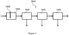
- methanation reagents enter a methanation reactor 1605 which can be part of a series (not shown) of such reactors.
- the water is separated from the methanation products via a means 1625 for separating this water, such as a heat exchanger for example.
- the dehydrated synthetic natural gas is then treated by a means of separation 1645 from carbon dioxide.
- the synthetic natural gas is treated by a separation means 1655 of the dihydrogen so that this synthetic natural gas meets the injection specifications on a distribution network.
- the steps of separation of water, carbon dioxide and dihydrogen can be carried out in any order.
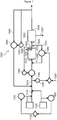
- the reactor 1005 is preferably an isothermal methanation reactor with a fluidized bed operating at a predetermined temperature. Fluidization of the catalyst by the reaction mixture allows almost perfect homogenization of the temperatures at all points of the catalytic layer and the reactor 1005 can be assimilated to an isothermal reactor.
- this reactor 1005 can be a boiling water reactor, known to those skilled in the art under the abbreviation “BWR” (for Boiling Water Reactor). In other variants, this reactor 1005 can be a wall-cooled bed reactor or an exchanger reactor.
- BWR Boiling Water Reactor
- the reactor 1005 has at least one heat exchange surface 1006 positioned in the fluidized bed of the isothermal reactor 1005.
- This surface 1006 is, for example, a tube configured to form a circulation loop of a fluid from the outside of the reactor 1005 towards the inside of this reactor 1005, the fluid being cooled outside the reactor 1005.
- This fluid is, for example, saturated or superheated steam.
- This reactor 1005 is configured to carry out the methanation of carbon dioxide.
- This reactor 1005 has the inlet 1010 for syngas which is, for example, an orifice of the reactor 1005 provided with a connector (not shown) compatible with the supply line 1015 of syngas.
- the synthetic natural gases leave the reactor 1005 via the outlet 1020 of the reactor.
- This outlet 1020 is, for example, an orifice connected to a connector (not shown) allowing the fixing of a sealed pipe for transporting synthetic natural gas.
- the water separation means 1025 is, for example, a heat exchanger for cooling the synthetic natural gases to a temperature below the dew point of the water. This temperature is preferably between -5 ° C and + 60 ° C. Preferably, this temperature is between 5 ° C and 40 ° C.
- the separation means 1025 is configured to cool the synthetic natural gases to a temperature below the water dew point temperature under the operating conditions of the reactor 1005 considered.
- the water thus separated is collected by an outlet 1027 for water and can be used by the means 1105 of water electrolysis.
- the water separation means 1025 includes the inlet 1030 for synthetic natural gas.
- This inlet 1030 is, for example, an orifice associated with a connector (not shown) to be connected to the sealed pipe for transporting the synthetic natural gas coming from the reactor 1005.
- the water separation means 1025 includes the outlet 1035 for dehydrated synthetic natural gas.
- This output 1035 is, for example, an orifice associated with a connector (not shown) to be connected to a sealed pipe (not referenced) for transporting dehydrated synthetic natural gas.
- the bypass 1040 is, for example, a sealed pipe connected to the pipe for transporting dehydrated synthetic natural gas to capture part of the flow passing through this transport pipe.
- This bypass 1040 injects the dehydrated synthetic natural gases into the syngas supply line 1015.
- syngas and dehydrated synthetic natural gas cooled by the water separation process, form a mixture which, in reactor 1005, reduces the exothermicity of the methanation reaction, and thus improves the specifications.
- the mixture produced makes it possible to avoid the downstream separation of H 2 in the SNG.
- the supply line 1015 is sealed and receives, for example, CO 2 and H 2 from a means of water electrolysis.
- the electrolysis means 1105 is, for example, an electrolyser for water, configured to separate molecules of water into molecules of oxygen and into molecules of dihydrogen.
- the carbon dioxide in the supply line 1110 is conditioned by compression and by treatment of the impurities upstream of the device 1000.
- the injection means 1115 is, for example, a valve for injecting dihydrogen into the supply line 1015.
- the means 1125 for conditioning carbon dioxide is, for example, an electronic control circuit which multiplies the flow rate of dihydrogen measured by a determined reference coefficient 1126. The result of this multiplication is communicated to a carbon dioxide flow control valve, this result corresponding to a flow setpoint.
- the H 2 / CO 2 ratio must be adjusted in close stoichiometry, that is to say between 3.9 and 4.1 in order to limit the excess reagents. This ratio is controlled by regulating the CO 2 flow rate as a function of the H 2 flow rate measurement and a stoichiometric factor.
- the preheating means 1060 preferably heats the mixture to a temperature above the dew point temperature of the mixture to avoid any pre-condensation of the mixture and below the operating temperature of the reactor to allow cooling of the reactor 1005.
- the mixture preheating means 1060 heats this mixture to a temperature between 50 ° C and 300 ° C.
- the means 1060 for preheating the mixture heats this mixture to a temperature above 50 ° C. and below the operating temperature of the reactor 1005.
- This preheating means 1060 is, for example, a heat exchanger for heating the syngas.
- the temperature of the preheating means 1060 varies as a function of the temperature sensed and of a predetermined set temperature. If the sensed temperature is higher than the set temperature, the power of the preheating means 1060 is reduced. Conversely, the power of the preheating means 1060 is increased when the sensed temperature is lower than the set temperature.
- the deflection pipe 1070 is, for example, a sealed pipe.
- the inlet 1075 is, for example, an orifice opening onto the inside of the synthetic natural gas transport pipe, upstream of the water separation means 1025.
- the output 1080 is, for example, an orifice for injecting synthetic natural gas into the mixture, downstream of the preheating means 1060.
- the synthetic natural gases, hot make it possible to maintain the flow rate in the reactor 1005.
- the syngas flow is entirely a function of the quantities of electricity available.
- the conditions hydrodynamics should be kept as constant as possible.
- the available electrical power is insufficient and consequently the syngas flow is reduced, it is advisable to maintain an overall flow entering the reactor 1005 constant or to opt for a very flexible technology.
- the flow at the outlet of preheating means 1060 is supplemented by a hot recirculation coming directly from the outlet 1020 of the reactor 1005 via the deflection pipe 1070.
- the using a hot recirculating fluid does not cause thermal imbalance in the reactor 1005 but makes the device 1000 very flexible.
- the flow measurement means 1085 can be of any type known to a person skilled in the art which is suitable for measuring the gas flow, such as an anemometer, a Coriolis effect flow meter, a vortex effect flow meter or an electromagnetic flow meter for example .
- Recirculator 1090 is similar to recirculator 1055 in structural terms.
- the control of this recirculator 1090 is carried out as a function of the flow rate measured by the measurement means 1085 of the flow rate and of a set flow rate value 1087. If the measured flow rate is less than a predetermined flow rate 1087, the recirculator 1090 is operated so as to bridge the difference between the measured flow rate and the target flow rate 1087 with an equivalent flow rate of synthetic natural gas.
- the sensor 1050 is, for example, an electronic circuit for estimating the PCS associated with a gas chromatograph determining a composition of the SNG in the bypass 1040 or in the output 1035.
- the recirculator 1055 aims to compensate for the pressure or pressure losses successively in the preheating means 1060, the reactor 1005, the means of separation 1025 of water particularly for the device 1000 described with regard to the figure 1 and of all the connection pipes of these various pieces of equipment.
- the recirculator 1055 is, for example, a fan, a booster or an ejector.
- the device 1000 includes a means 1085 for measuring the syngas flow downstream of the place of mixing, the recirculator 1090, of the natural gas entering the deflection pipe 1070, being controlled as a function of the measured syngas flow.
- this embodiment makes it possible to eliminate the successive stages of separation of H 2 and CO 2 .
- the implementation of the device 1000 that is the object of the present invention, makes it possible to obtain synthesis gas close to the specifications of the gas network requiring few additional operations.
- the device 1000 can thus be implemented for a pressure range between 1 bar and 100 bar and a predetermined temperature range between 150 ° C and 700 ° C.
- This method 1600 is implemented, for example, by the device 1000 which is the subject of the present invention and described with reference to the figure 1 .
- the Wobbe index of the synthetic natural gas produced by the device 1000 as a function of the recirculation rate, on the abscissa, and of the nature of the synthetic natural gas recirculated at the inlet of the methanation reactor 1005.
- recirculation rate the quantity of gas exited from the separation means 1025 reinjected into the line 1015 divided by the total quantity of gas exited from the separation means 1025.
- the figure 6 allows to visualize the evolution of the normalized exothermicity of the reactor, ie the heat to be evacuated compared to a case without recirculation, according to the rate of recirculation for the reference configuration and the device 1000 described above .
- the increase in the recirculation rate causes a linear drop in the exothermicity of the reactor.
- the recirculated SNG plays the role of thermal flywheel which is more marked in the presence of H 2 O due to a higher heat capacity.
- the fact of reaching a level of recirculation corresponding to an ideal operating temperature of the device 1000, makes it possible to get rid of the internal exchanger of the reactor and the separation of H 2 from setting to specifications. Beyond that, the reactor is allothermic and therefore requires additional heat to maintain the reactions.
- the molar fractions of the H 2 , CO 2 and CH 4 species as a function of the recirculation rate for the simulated configuration evolves in the direction of improving the quality of the SNG with the device 1000 for recirculating the dehydrated SNG.
Landscapes
- Chemical & Material Sciences (AREA)
- Chemical Kinetics & Catalysis (AREA)
- Engineering & Computer Science (AREA)
- Organic Chemistry (AREA)
- Oil, Petroleum & Natural Gas (AREA)
- Metallurgy (AREA)
- Electrochemistry (AREA)
- Materials Engineering (AREA)
- General Chemical & Material Sciences (AREA)
- Inorganic Chemistry (AREA)
- Organic Low-Molecular-Weight Compounds And Preparation Thereof (AREA)
- Electrolytic Production Of Non-Metals, Compounds, Apparatuses Therefor (AREA)
- Carbon And Carbon Compounds (AREA)
- Oxygen, Ozone, And Oxides In General (AREA)
Claims (13)
- Vorrichtung (1000) zum Erzeugen von Synthesegas, dadurch gekennzeichnet, dass sie umfasst:- ein Elektrolysemittel (1105) für Wasser zum Erzeugen des Disauerstoffs und des Diwasserstoffs,- eine Leitung (1110) zur Versorgung mit Kohlenwasserstoff,- ein Mittel (1115) zum Einschießen von Diwasserstoff, der aus dem Elektrolysemittel stammt, in eine Leitung (1015) zur Versorgung mit Kohlenwasserstoff durch die Leitung zum Versorgen mit Kohlendioxid (1110), wobei dieses Kohlendioxid und dieser Diwasserstoff ein Synthesegas bilden,- einen Isotherm-Reaktor (1005) zur Methanerzeugung, umfassend:- einen Eingang (1010) für das Synthesegas, der an die Versorgungsleitung (1015) für Synthesegas angeschlossen ist, und- einen Ausgang (1020) für Synthese-Erdgas,- ein Abscheidemittel (1025) für Wasser, umfassend:- einen Eingang (1030) für Synthese-Erdgas, der an den Ausgang für Synthese-Erdgas angeschlossen ist, und- einen Ausgang (1035) für entwässertes Synthese-Erdgas und- eine Ableitung (1040) eines Teils des entwässerten Synthese-Erdgases ab dem Ausgang des Abscheidemittels für Wasser zu der Versorgungsleitung (1015) für Synthesegas, damit dem Reaktor eine Mischung aus abgeleitetem Synthesegas und abgeleitetem Synthese-Erdgas geliefert wird.
- Vorrichtung (1000) gemäß Anspruch 1, die umfasst:- ein Messmittel (1120) des Diwasserstoff-Durchsatzes, der per Elektrolyse erzeugt ist, und- ein Mittel (1125) zum Aufbereiten des Kohlenwasserstoff-Durchsatzes in der Leitung (1015) zur Versorgung mit Kohlenstoff in Abhängigkeit von dem gemessenen Diwasserstoff-Durchsatz.
- Vorrichtung (1000) gemäß einem der Ansprüche 1 bis 2, die umfasst:- nach dem Reaktor (1005) und vor dem Abscheidemittel (1025) für Wasser einen Sensor (1062) einer Temperatur des Synthese-Erdgases und- vor dem Eingang des Reaktors ein Mittel (1060) zum Vorheizen der Mischung in Abhängigkeit von der erfassten Temperatur.
- Vorrichtung (1000) gemäß einem der Ansprüche 1 bis 3, die umfasst:- einen Sensor (1050) einer physikalischen Größe, die einen Heizwert des Brennmaterials oder eine Zusammensetzung des entwässerten Synthese-Erdgases darstellt, und- einen Rücklauf (1055) des in die Ableitung eingetretenen Erdgases, der in Abhängigkeit von einem Wert der erfassten physikalischen Größe gesteuert ist.
- Vorrichtung (1000) gemäß einem der Ansprüche 1 bis 4, die eine Ableitungsleitung (1070) eines Teils der heißen Produkte aus Methanerzeugungsreaktionen umfasst, umfassend:- einen Eingang (1075), der zwischen dem Ausgang des Reaktors (1005) und dem Abscheidemittel (1025) für Wasser angeordnet ist, und- einen Ausgang (1080), der vor dem Eingang des Reaktors angeordnet ist.
- Vorrichtung (1000) gemäß einem der Ansprüche 1 bis 5, die umfasst:- ein Messmittel (1085) des Durchsatzes des Synthesegases nach dem Ort der Mischung und- einen Rücklauf (1090) des in die Ableitungsleitung (1070) eingetretenen heißen Erdgases, der in Abhängigkeit von dem gemessenen Durchsatz des Synthesegases gesteuert ist.
- Vorrichtung (1000) gemäß einem der Ansprüche 1 bis 6, bei der das Abscheidemittel (1025) zum Abkühlen der Synthese-Erdgase auf eine zwischen -5° C und +60° C inbegriffene Temperatur ausgestaltet ist.
- Vorrichtung (1000) gemäß Anspruch 7, bei der das Abscheidemittel (1025) für Wasser zum Abkühlen der Synthese-Erdgase auf eine Temperatur ausgestaltet ist, die unter der Taupunkttemperatur des Wassers bei den betrachteten Betriebsbedingungen des Reaktors (1005) liegt.
- Vorrichtung (1000) gemäß den Ansprüchen 7 bis 8, bei der das Abscheidemittel (1025) zum Abkühlen der Synthese-Erdgase auf eine Temperatur ausgestaltet ist, die unter der Taupunkttemperatur bei den Betriebsbedingungen des Reaktors (1005) liegt.
- Vorrichtung (1000) gemäß einem der Ansprüche 1 bis 9, bei der der Isotherm-Reaktor ein Wirbelbett-Reaktor ist.
- Vorrichtung (1000) gemäß Anspruch 10, die wenigstens eine Oberfläche (1006) zum Wärmetausch umfasst, die im Wirbelbett angeordnet ist.
- Vorrichtung (1600) zum Erzeugen von Synthesegas, dadurch gekennzeichnet, dass sie umfasst:- ein Elektrolysemittel (1640) für Wasser zum Erzeugen des Disauerstoffs und des Diwasserstoffs,- einen Schritt (1645) zur Versorgung mit Kohlenwasserstoff,- einen Schritt (1650) zum Einschießen von Diwasserstoff, der aus dem Elektrolyseschritt stammt, in eine Leitung zur Versorgung mit Kohlenwasserstoff, der aus dem Schritt zum Versorgen mit Kohlendioxid stammt, wobei dieses Kohlendioxid und dieser Diwasserstoff ein Synthesegas formen,- einen Reaktionsschritt zur Methanerzeugung (1605), umfassend:- einen Eingangsschritt (1610) in einen Isotherm-Reaktor zur Methanerzeugung des Synthesegases durch die Versorgungsleitung für Synthesegas und- einen Ausgangsschritt (1615) für Synthese-Erdgas,- einen Abscheideschritt (1620) für Wasser, umfassend:- einen Eingangsschritt (1625) für Synthese-Erdgas und- einen Ausgangsschritt (1630) für entwässertes Synthese-Erdgas und- einen Ableitungsschritt (1635) eines Teils des entwässerten Synthese-Erdgases am Ausgang des Abscheideschritts für Wasser zu der Versorgungsleitung für Synthesegas, damit dem Reaktor eine Mischung aus abgeleitetem Synthesegas und abgeleitetem Synthese-Erdgas geliefert wird.
- Vorrichtung (1600) gemäß Anspruch 12, die einen Ableitungsschritt 1655 eines Teils der heißen Produkte aus Methanerzeugungsreaktionen nach oben zum Methanerzeugungsschritt umfasst.
Priority Applications (1)
| Application Number | Priority Date | Filing Date | Title |
|---|---|---|---|
| PL16757276T PL3322776T3 (pl) | 2015-07-16 | 2016-07-12 | Urządzenie i sposób wytwarzania syntetycznego gazu |
Applications Claiming Priority (3)
| Application Number | Priority Date | Filing Date | Title |
|---|---|---|---|
| FR1556743A FR3038908A1 (fr) | 2015-07-16 | 2015-07-16 | Dispositif et procede de production de gaz de synthese |
| FR1650498A FR3038912B1 (fr) | 2015-07-16 | 2016-01-21 | Dispositif et procede de production de gaz de synthese |
| PCT/FR2016/051790 WO2017009575A1 (fr) | 2015-07-16 | 2016-07-12 | Dispositif et procédé de production de gaz de synthèse |
Publications (2)
| Publication Number | Publication Date |
|---|---|
| EP3322776A1 EP3322776A1 (de) | 2018-05-23 |
| EP3322776B1 true EP3322776B1 (de) | 2020-04-29 |
Family
ID=55590047
Family Applications (2)
| Application Number | Title | Priority Date | Filing Date |
|---|---|---|---|
| EP16757277.5A Active EP3322777B1 (de) | 2015-07-16 | 2016-07-12 | Vorrichtung und verfahren zur herstellung von synthesegas |
| EP16757276.7A Active EP3322776B1 (de) | 2015-07-16 | 2016-07-12 | Vorrichtung und verfahren zur herstellung von synthesegas |
Family Applications Before (1)
| Application Number | Title | Priority Date | Filing Date |
|---|---|---|---|
| EP16757277.5A Active EP3322777B1 (de) | 2015-07-16 | 2016-07-12 | Vorrichtung und verfahren zur herstellung von synthesegas |
Country Status (12)
| Country | Link |
|---|---|
| EP (2) | EP3322777B1 (de) |
| KR (2) | KR20180030679A (de) |
| CN (2) | CN107922862A (de) |
| AU (2) | AU2016294487B2 (de) |
| BR (2) | BR112018000921B1 (de) |
| CL (2) | CL2018000104A1 (de) |
| DK (2) | DK3322777T3 (de) |
| ES (2) | ES2804548T3 (de) |
| FR (3) | FR3038908A1 (de) |
| PL (2) | PL3322777T3 (de) |
| SG (2) | SG11201800384XA (de) |
| WO (2) | WO2017009575A1 (de) |
Families Citing this family (10)
| Publication number | Priority date | Publication date | Assignee | Title |
|---|---|---|---|---|
| FR3038908A1 (fr) * | 2015-07-16 | 2017-01-20 | Gdf Suez | Dispositif et procede de production de gaz de synthese |
| US10815442B2 (en) | 2018-07-02 | 2020-10-27 | Sogang University Research & Business Development Foundation | Apparatus and process for synthesizing natural gas using carbon dioxide and water in air |
| CN109217370A (zh) * | 2018-10-26 | 2019-01-15 | 中国科学院青岛生物能源与过程研究所 | 一种风/光与生物质互补的发电和化学品储能系统及控制方法 |
| JP7432997B2 (ja) * | 2019-05-24 | 2024-02-19 | 三菱重工業株式会社 | 合成物生産システム及び合成物生産方法 |
| KR102334163B1 (ko) * | 2020-01-30 | 2021-12-01 | 고등기술연구원연구조합 | 메탄 생성 장치 및 이의 제어 방법 |
| CA3138540A1 (en) * | 2020-11-13 | 2022-05-13 | Lummus Technology Llc | Methods and systems for converting carbon oxides to olefins |
| US12503777B2 (en) | 2022-01-31 | 2025-12-23 | Honda Motor Co., Ltd. | Electrolysis system |
| CN116516360A (zh) * | 2022-01-31 | 2023-08-01 | 本田技研工业株式会社 | 电解系统 |
| KR102593106B1 (ko) * | 2023-05-16 | 2023-10-25 | 문희성 | 스마트 rx가스 제너레이터 시스템 |
| CN116590063B (zh) * | 2023-05-18 | 2025-09-12 | 中石化宁波工程有限公司 | 合成气制备天然气的方法及其装置 |
Citations (2)
| Publication number | Priority date | Publication date | Assignee | Title |
|---|---|---|---|---|
| WO2015011503A1 (en) * | 2013-07-26 | 2015-01-29 | Advanced Plasma Power Limited | Process for producing a substitute natural gas |
| WO2016193751A1 (en) * | 2015-06-04 | 2016-12-08 | Advanced Plasma Power Limited | Process for producing a substitute natural gas from synthesis gas |
Family Cites Families (19)
| Publication number | Priority date | Publication date | Assignee | Title |
|---|---|---|---|---|
| NL168191C (nl) * | 1970-02-20 | 1982-03-16 | Shell Int Research | Werkwijze voor de bereiding en koeling van synthesegas. |
| US3967936A (en) * | 1975-01-02 | 1976-07-06 | The United States Of America As Represented By The United States Energy Research And Development Administration | Methanation process utilizing split cold gas recycle |
| DE3032123A1 (de) * | 1979-10-22 | 1981-04-30 | Conoco Inc., 74601 Ponca City, Okla. | Verfahren zur herstellung eines methan enthaltenden ersatz-erdgases |
| CN1300189C (zh) * | 2005-02-05 | 2007-02-14 | 浙江大学 | 烯烃气相聚合反应在线控制装置及其方法 |
| US20090247653A1 (en) * | 2006-04-06 | 2009-10-01 | Fluor Technologies Corporation | Configurations And Methods of SNG Production |
| US7398172B2 (en) * | 2006-05-31 | 2008-07-08 | International Business Machines Corporation | Method and system of providing a dynamic sampling plan for integrated metrology |
| EP2110425B2 (de) * | 2008-04-16 | 2022-03-30 | Casale Sa | Verfahren und Anlage zur Erdgassubstitution |
| GB201019054D0 (en) * | 2010-11-11 | 2010-12-29 | Johnson Matthey Plc | Process |
| CN102329671A (zh) * | 2011-09-13 | 2012-01-25 | 西南化工研究设计院 | 一种煤制合成天然气的甲烷化工艺 |
| CN102827657A (zh) * | 2012-08-27 | 2012-12-19 | 东华工程科技股份有限公司 | 一种煤制天然气的等温甲烷化工艺方法 |
| CN103740425B (zh) * | 2012-10-17 | 2016-08-17 | 中国石油化工股份有限公司 | 合成气生产替代天然气的方法 |
| BR112015024556B1 (pt) * | 2013-03-26 | 2020-01-28 | Outotec (Finland) Oy | método e planta para produção de metano |
| FR3004179B1 (fr) * | 2013-04-08 | 2015-05-01 | Commissariat Energie Atomique | Procedes d'obtention de gaz combustible a partir d'electrolyse de l'eau (eht) ou de co-electrolyse avec h2o/co2 au sein d'une meme enceinte, reacteur catalytique et systeme associes |
| ITRM20130367A1 (it) * | 2013-06-26 | 2014-12-27 | Agenzia Naz Per Le Nuove Tecnologie L Ener | Gruppo per la produzione di metano da gas emesso dal suolo |
| FR3009308B1 (fr) * | 2013-08-01 | 2015-09-11 | Commissariat Energie Atomique | Procede de conversion thermochimique d'une charge carbonee en gaz de synthese contenant majoritairement h2 et co. |
| FR3012468B1 (fr) * | 2013-10-28 | 2016-03-11 | Gdf Suez | Dispositif et procede de production de gaz naturel de substitution et reseau le comportant |
| FR3014451B1 (fr) * | 2013-12-05 | 2016-01-01 | Commissariat Energie Atomique | Procede de production de gaz de synthese par coelectrolyse |
| CN104593804B (zh) * | 2015-01-15 | 2015-11-18 | 东北石油大学 | 一种高温电解co2/h2o制备合成气系统及其应用 |
| FR3038908A1 (fr) * | 2015-07-16 | 2017-01-20 | Gdf Suez | Dispositif et procede de production de gaz de synthese |
-
2015
- 2015-07-16 FR FR1556743A patent/FR3038908A1/fr active Pending
-
2016
- 2016-01-21 FR FR1650497A patent/FR3038911B1/fr active Active
- 2016-01-21 FR FR1650498A patent/FR3038912B1/fr active Active
- 2016-07-12 BR BR112018000921-0A patent/BR112018000921B1/pt active IP Right Grant
- 2016-07-12 KR KR1020187004818A patent/KR20180030679A/ko not_active Withdrawn
- 2016-07-12 SG SG11201800384XA patent/SG11201800384XA/en unknown
- 2016-07-12 PL PL16757277T patent/PL3322777T3/pl unknown
- 2016-07-12 KR KR1020187004815A patent/KR20180030677A/ko not_active Withdrawn
- 2016-07-12 DK DK16757277.5T patent/DK3322777T3/da active
- 2016-07-12 BR BR112018000920-2A patent/BR112018000920B1/pt active IP Right Grant
- 2016-07-12 SG SG11201800380TA patent/SG11201800380TA/en unknown
- 2016-07-12 CN CN201680044618.5A patent/CN107922862A/zh active Pending
- 2016-07-12 ES ES16757276T patent/ES2804548T3/es active Active
- 2016-07-12 PL PL16757276T patent/PL3322776T3/pl unknown
- 2016-07-12 AU AU2016294487A patent/AU2016294487B2/en active Active
- 2016-07-12 WO PCT/FR2016/051790 patent/WO2017009575A1/fr not_active Ceased
- 2016-07-12 WO PCT/FR2016/051793 patent/WO2017009577A1/fr not_active Ceased
- 2016-07-12 ES ES16757277T patent/ES2804550T3/es active Active
- 2016-07-12 DK DK16757276.7T patent/DK3322776T3/da active
- 2016-07-12 CN CN201680049617.XA patent/CN107922863A/zh active Pending
- 2016-07-12 EP EP16757277.5A patent/EP3322777B1/de active Active
- 2016-07-12 EP EP16757276.7A patent/EP3322776B1/de active Active
- 2016-07-12 AU AU2016294485A patent/AU2016294485B2/en active Active
-
2018
- 2018-01-12 CL CL2018000104A patent/CL2018000104A1/es unknown
- 2018-01-12 CL CL2018000105A patent/CL2018000105A1/es unknown
Patent Citations (2)
| Publication number | Priority date | Publication date | Assignee | Title |
|---|---|---|---|---|
| WO2015011503A1 (en) * | 2013-07-26 | 2015-01-29 | Advanced Plasma Power Limited | Process for producing a substitute natural gas |
| WO2016193751A1 (en) * | 2015-06-04 | 2016-12-08 | Advanced Plasma Power Limited | Process for producing a substitute natural gas from synthesis gas |
Also Published As
| Publication number | Publication date |
|---|---|
| AU2016294487B2 (en) | 2020-05-07 |
| BR112018000920B1 (pt) | 2022-03-08 |
| SG11201800384XA (en) | 2018-02-27 |
| CL2018000105A1 (es) | 2019-02-01 |
| PL3322776T3 (pl) | 2020-11-02 |
| EP3322777A1 (de) | 2018-05-23 |
| DK3322776T3 (da) | 2020-07-13 |
| FR3038912A1 (fr) | 2017-01-20 |
| CN107922862A (zh) | 2018-04-17 |
| WO2017009577A1 (fr) | 2017-01-19 |
| KR20180030679A (ko) | 2018-03-23 |
| FR3038912B1 (fr) | 2017-07-28 |
| BR112018000921B1 (pt) | 2022-03-08 |
| SG11201800380TA (en) | 2018-02-27 |
| CN107922863A (zh) | 2018-04-17 |
| AU2016294487A1 (en) | 2018-02-08 |
| ES2804550T3 (es) | 2021-02-08 |
| CL2018000104A1 (es) | 2019-02-01 |
| BR112018000920A2 (pt) | 2018-09-11 |
| FR3038911A1 (fr) | 2017-01-20 |
| KR20180030677A (ko) | 2018-03-23 |
| AU2016294485A1 (en) | 2018-02-08 |
| AU2016294485B2 (en) | 2020-11-26 |
| ES2804548T3 (es) | 2021-02-08 |
| BR112018000921A2 (pt) | 2018-09-11 |
| EP3322777B1 (de) | 2020-05-06 |
| WO2017009575A1 (fr) | 2017-01-19 |
| EP3322776A1 (de) | 2018-05-23 |
| FR3038911B1 (fr) | 2017-07-28 |
| PL3322777T3 (pl) | 2020-11-02 |
| FR3038908A1 (fr) | 2017-01-20 |
| DK3322777T3 (da) | 2020-07-13 |
Similar Documents
| Publication | Publication Date | Title |
|---|---|---|
| EP3322777B1 (de) | Vorrichtung und verfahren zur herstellung von synthesegas | |
| CA2565936A1 (fr) | Procede de production de gaz de synthese a partir de matiere carbonee et d'energie electrique | |
| EP3795537B1 (de) | Katalytischer festbettreaktor mit einem elektrischen heizelement, einheit zur herstellung von wasserstoff durch dampfreformierung, die einen solchen reaktor und einen elektrischen dampferzeuger umfasst, entsprechendes betriebsverfahren | |
| EP3031884B1 (de) | Vergasungsverfahren einer ladung von kohlenstoffhaltigem material mit optimierter materialeffizienz und optimierten produktionskosten | |
| FR2957352A1 (fr) | Procede de craquage catalytique avec controle fin de la teneur en coke residuelle sur le catalyseur apres regeneration | |
| EP3322778B1 (de) | Vorrichtung und ein verfahren zur herstellung von synthesegas | |
| CA2691766A1 (fr) | Procede de production d'hydrogene avec captation totale du co2 et reduction du methane non converti | |
| FR3035394A1 (fr) | Procede de conversion thermochimique d'une charge carbonee mis en œuvre en continu dans un reacteur utilisant au moins en partie l'energie du rayonnement solaire. | |
| EP3442695B1 (de) | Vorrichtung und verfahren für die gleichzeitige erzeugung von methanol und synthetischem methan | |
| CA2925440C (fr) | Reacteur de methanation pour faire reagir de l'hydrogene avec au moins un compose a base de carbone et produire du methane et de l'eau | |
| EP3443051A1 (de) | Vorrichtung und verfahren zur gleichzeitigen erzeugung von methanol und synthesemethan | |
| WO2022013239A1 (fr) | Dispositif et procédé de production hybride de dihydrogène de synthèse et/ou de méthane de synthèse | |
| WO2011148067A1 (fr) | Procédé de conversion à la vapeur de gaz de synthèse et appareil pour réaliser ce procédé | |
| Liu et al. | A comprehensive experimental study of the solar-driven biomass gasification under CO2 atmosphere in a combined drop-tube and fixed-bed reactor | |
| WO2025132364A1 (fr) | Procédé et dispositif de conversion du gaz à l'eau inversée multi-zones | |
| WO2025132366A1 (fr) | Dispositif de distribution d'unité de conversion du gaz à l'eau inversée | |
| FR3072966A1 (fr) | Systeme de production d'un hydrocarbure de synthese a conversion elevee avec valorisation des gaz et a vieillissement maitrise |
Legal Events
| Date | Code | Title | Description |
|---|---|---|---|
| STAA | Information on the status of an ep patent application or granted ep patent |
Free format text: STATUS: THE INTERNATIONAL PUBLICATION HAS BEEN MADE |
|
| PUAI | Public reference made under article 153(3) epc to a published international application that has entered the european phase |
Free format text: ORIGINAL CODE: 0009012 |
|
| STAA | Information on the status of an ep patent application or granted ep patent |
Free format text: STATUS: REQUEST FOR EXAMINATION WAS MADE |
|
| 17P | Request for examination filed |
Effective date: 20180209 |
|
| AK | Designated contracting states |
Kind code of ref document: A1 Designated state(s): AL AT BE BG CH CY CZ DE DK EE ES FI FR GB GR HR HU IE IS IT LI LT LU LV MC MK MT NL NO PL PT RO RS SE SI SK SM TR |
|
| AX | Request for extension of the european patent |
Extension state: BA ME |
|
| DAV | Request for validation of the european patent (deleted) | ||
| DAX | Request for extension of the european patent (deleted) | ||
| STAA | Information on the status of an ep patent application or granted ep patent |
Free format text: STATUS: EXAMINATION IS IN PROGRESS |
|
| 17Q | First examination report despatched |
Effective date: 20190527 |
|
| GRAP | Despatch of communication of intention to grant a patent |
Free format text: ORIGINAL CODE: EPIDOSNIGR1 |
|
| STAA | Information on the status of an ep patent application or granted ep patent |
Free format text: STATUS: GRANT OF PATENT IS INTENDED |
|
| INTG | Intention to grant announced |
Effective date: 20191030 |
|
| GRAJ | Information related to disapproval of communication of intention to grant by the applicant or resumption of examination proceedings by the epo deleted |
Free format text: ORIGINAL CODE: EPIDOSDIGR1 |
|
| STAA | Information on the status of an ep patent application or granted ep patent |
Free format text: STATUS: EXAMINATION IS IN PROGRESS |
|
| GRAR | Information related to intention to grant a patent recorded |
Free format text: ORIGINAL CODE: EPIDOSNIGR71 |
|
| GRAS | Grant fee paid |
Free format text: ORIGINAL CODE: EPIDOSNIGR3 |
|
| STAA | Information on the status of an ep patent application or granted ep patent |
Free format text: STATUS: GRANT OF PATENT IS INTENDED |
|
| GRAA | (expected) grant |
Free format text: ORIGINAL CODE: 0009210 |
|
| STAA | Information on the status of an ep patent application or granted ep patent |
Free format text: STATUS: THE PATENT HAS BEEN GRANTED |
|
| INTC | Intention to grant announced (deleted) | ||
| INTG | Intention to grant announced |
Effective date: 20200318 |
|
| AK | Designated contracting states |
Kind code of ref document: B1 Designated state(s): AL AT BE BG CH CY CZ DE DK EE ES FI FR GB GR HR HU IE IS IT LI LT LU LV MC MK MT NL NO PL PT RO RS SE SI SK SM TR |
|
| REG | Reference to a national code |
Ref country code: GB Ref legal event code: FG4D Free format text: NOT ENGLISH |
|
| REG | Reference to a national code |
Ref country code: CH Ref legal event code: EP |
|
| REG | Reference to a national code |
Ref country code: DE Ref legal event code: R096 Ref document number: 602016035130 Country of ref document: DE |
|
| REG | Reference to a national code |
Ref country code: AT Ref legal event code: REF Ref document number: 1263292 Country of ref document: AT Kind code of ref document: T Effective date: 20200515 |
|
| REG | Reference to a national code |
Ref country code: IE Ref legal event code: FG4D Free format text: LANGUAGE OF EP DOCUMENT: FRENCH |
|
| REG | Reference to a national code |
Ref country code: DK Ref legal event code: T3 Effective date: 20200708 |
|
| REG | Reference to a national code |
Ref country code: NL Ref legal event code: FP |
|
| REG | Reference to a national code |
Ref country code: LT Ref legal event code: MG4D |
|
| PG25 | Lapsed in a contracting state [announced via postgrant information from national office to epo] |
Ref country code: LT Free format text: LAPSE BECAUSE OF FAILURE TO SUBMIT A TRANSLATION OF THE DESCRIPTION OR TO PAY THE FEE WITHIN THE PRESCRIBED TIME-LIMIT Effective date: 20200429 Ref country code: NO Free format text: LAPSE BECAUSE OF FAILURE TO SUBMIT A TRANSLATION OF THE DESCRIPTION OR TO PAY THE FEE WITHIN THE PRESCRIBED TIME-LIMIT Effective date: 20200729 Ref country code: FI Free format text: LAPSE BECAUSE OF FAILURE TO SUBMIT A TRANSLATION OF THE DESCRIPTION OR TO PAY THE FEE WITHIN THE PRESCRIBED TIME-LIMIT Effective date: 20200429 Ref country code: SE Free format text: LAPSE BECAUSE OF FAILURE TO SUBMIT A TRANSLATION OF THE DESCRIPTION OR TO PAY THE FEE WITHIN THE PRESCRIBED TIME-LIMIT Effective date: 20200429 Ref country code: IS Free format text: LAPSE BECAUSE OF FAILURE TO SUBMIT A TRANSLATION OF THE DESCRIPTION OR TO PAY THE FEE WITHIN THE PRESCRIBED TIME-LIMIT Effective date: 20200829 Ref country code: PT Free format text: LAPSE BECAUSE OF FAILURE TO SUBMIT A TRANSLATION OF THE DESCRIPTION OR TO PAY THE FEE WITHIN THE PRESCRIBED TIME-LIMIT Effective date: 20200831 Ref country code: GR Free format text: LAPSE BECAUSE OF FAILURE TO SUBMIT A TRANSLATION OF THE DESCRIPTION OR TO PAY THE FEE WITHIN THE PRESCRIBED TIME-LIMIT Effective date: 20200730 |
|
| REG | Reference to a national code |
Ref country code: AT Ref legal event code: MK05 Ref document number: 1263292 Country of ref document: AT Kind code of ref document: T Effective date: 20200429 |
|
| PG25 | Lapsed in a contracting state [announced via postgrant information from national office to epo] |
Ref country code: HR Free format text: LAPSE BECAUSE OF FAILURE TO SUBMIT A TRANSLATION OF THE DESCRIPTION OR TO PAY THE FEE WITHIN THE PRESCRIBED TIME-LIMIT Effective date: 20200429 Ref country code: RS Free format text: LAPSE BECAUSE OF FAILURE TO SUBMIT A TRANSLATION OF THE DESCRIPTION OR TO PAY THE FEE WITHIN THE PRESCRIBED TIME-LIMIT Effective date: 20200429 Ref country code: LV Free format text: LAPSE BECAUSE OF FAILURE TO SUBMIT A TRANSLATION OF THE DESCRIPTION OR TO PAY THE FEE WITHIN THE PRESCRIBED TIME-LIMIT Effective date: 20200429 Ref country code: BG Free format text: LAPSE BECAUSE OF FAILURE TO SUBMIT A TRANSLATION OF THE DESCRIPTION OR TO PAY THE FEE WITHIN THE PRESCRIBED TIME-LIMIT Effective date: 20200729 |
|
| PG25 | Lapsed in a contracting state [announced via postgrant information from national office to epo] |
Ref country code: AL Free format text: LAPSE BECAUSE OF FAILURE TO SUBMIT A TRANSLATION OF THE DESCRIPTION OR TO PAY THE FEE WITHIN THE PRESCRIBED TIME-LIMIT Effective date: 20200429 |
|
| PG25 | Lapsed in a contracting state [announced via postgrant information from national office to epo] |
Ref country code: CZ Free format text: LAPSE BECAUSE OF FAILURE TO SUBMIT A TRANSLATION OF THE DESCRIPTION OR TO PAY THE FEE WITHIN THE PRESCRIBED TIME-LIMIT Effective date: 20200429 Ref country code: SM Free format text: LAPSE BECAUSE OF FAILURE TO SUBMIT A TRANSLATION OF THE DESCRIPTION OR TO PAY THE FEE WITHIN THE PRESCRIBED TIME-LIMIT Effective date: 20200429 Ref country code: EE Free format text: LAPSE BECAUSE OF FAILURE TO SUBMIT A TRANSLATION OF THE DESCRIPTION OR TO PAY THE FEE WITHIN THE PRESCRIBED TIME-LIMIT Effective date: 20200429 Ref country code: IT Free format text: LAPSE BECAUSE OF FAILURE TO SUBMIT A TRANSLATION OF THE DESCRIPTION OR TO PAY THE FEE WITHIN THE PRESCRIBED TIME-LIMIT Effective date: 20200429 Ref country code: RO Free format text: LAPSE BECAUSE OF FAILURE TO SUBMIT A TRANSLATION OF THE DESCRIPTION OR TO PAY THE FEE WITHIN THE PRESCRIBED TIME-LIMIT Effective date: 20200429 Ref country code: AT Free format text: LAPSE BECAUSE OF FAILURE TO SUBMIT A TRANSLATION OF THE DESCRIPTION OR TO PAY THE FEE WITHIN THE PRESCRIBED TIME-LIMIT Effective date: 20200429 |
|
| REG | Reference to a national code |
Ref country code: DE Ref legal event code: R097 Ref document number: 602016035130 Country of ref document: DE |
|
| REG | Reference to a national code |
Ref country code: ES Ref legal event code: FG2A Ref document number: 2804548 Country of ref document: ES Kind code of ref document: T3 Effective date: 20210208 |
|
| PG25 | Lapsed in a contracting state [announced via postgrant information from national office to epo] |
Ref country code: MC Free format text: LAPSE BECAUSE OF FAILURE TO SUBMIT A TRANSLATION OF THE DESCRIPTION OR TO PAY THE FEE WITHIN THE PRESCRIBED TIME-LIMIT Effective date: 20200429 Ref country code: SK Free format text: LAPSE BECAUSE OF FAILURE TO SUBMIT A TRANSLATION OF THE DESCRIPTION OR TO PAY THE FEE WITHIN THE PRESCRIBED TIME-LIMIT Effective date: 20200429 |
|
| REG | Reference to a national code |
Ref country code: CH Ref legal event code: PL |
|
| PLBE | No opposition filed within time limit |
Free format text: ORIGINAL CODE: 0009261 |
|
| STAA | Information on the status of an ep patent application or granted ep patent |
Free format text: STATUS: NO OPPOSITION FILED WITHIN TIME LIMIT |
|
| 26N | No opposition filed |
Effective date: 20210201 |
|
| PG25 | Lapsed in a contracting state [announced via postgrant information from national office to epo] |
Ref country code: CH Free format text: LAPSE BECAUSE OF NON-PAYMENT OF DUE FEES Effective date: 20200731 Ref country code: LU Free format text: LAPSE BECAUSE OF NON-PAYMENT OF DUE FEES Effective date: 20200712 Ref country code: LI Free format text: LAPSE BECAUSE OF NON-PAYMENT OF DUE FEES Effective date: 20200731 |
|
| PG25 | Lapsed in a contracting state [announced via postgrant information from national office to epo] |
Ref country code: SI Free format text: LAPSE BECAUSE OF FAILURE TO SUBMIT A TRANSLATION OF THE DESCRIPTION OR TO PAY THE FEE WITHIN THE PRESCRIBED TIME-LIMIT Effective date: 20200429 |
|
| PG25 | Lapsed in a contracting state [announced via postgrant information from national office to epo] |
Ref country code: IE Free format text: LAPSE BECAUSE OF NON-PAYMENT OF DUE FEES Effective date: 20200712 |
|
| PG25 | Lapsed in a contracting state [announced via postgrant information from national office to epo] |
Ref country code: TR Free format text: LAPSE BECAUSE OF FAILURE TO SUBMIT A TRANSLATION OF THE DESCRIPTION OR TO PAY THE FEE WITHIN THE PRESCRIBED TIME-LIMIT Effective date: 20200429 Ref country code: MT Free format text: LAPSE BECAUSE OF FAILURE TO SUBMIT A TRANSLATION OF THE DESCRIPTION OR TO PAY THE FEE WITHIN THE PRESCRIBED TIME-LIMIT Effective date: 20200429 Ref country code: CY Free format text: LAPSE BECAUSE OF FAILURE TO SUBMIT A TRANSLATION OF THE DESCRIPTION OR TO PAY THE FEE WITHIN THE PRESCRIBED TIME-LIMIT Effective date: 20200429 |
|
| PG25 | Lapsed in a contracting state [announced via postgrant information from national office to epo] |
Ref country code: MK Free format text: LAPSE BECAUSE OF FAILURE TO SUBMIT A TRANSLATION OF THE DESCRIPTION OR TO PAY THE FEE WITHIN THE PRESCRIBED TIME-LIMIT Effective date: 20200429 |
|
| P01 | Opt-out of the competence of the unified patent court (upc) registered |
Effective date: 20240212 |
|
| PGFP | Annual fee paid to national office [announced via postgrant information from national office to epo] |
Ref country code: PL Payment date: 20250625 Year of fee payment: 10 |
|
| PGFP | Annual fee paid to national office [announced via postgrant information from national office to epo] |
Ref country code: GB Payment date: 20250619 Year of fee payment: 10 Ref country code: DK Payment date: 20250619 Year of fee payment: 10 |
|
| PGFP | Annual fee paid to national office [announced via postgrant information from national office to epo] |
Ref country code: NL Payment date: 20250620 Year of fee payment: 10 Ref country code: BE Payment date: 20250619 Year of fee payment: 10 |
|
| PGFP | Annual fee paid to national office [announced via postgrant information from national office to epo] |
Ref country code: FR Payment date: 20250620 Year of fee payment: 10 |
|
| PGFP | Annual fee paid to national office [announced via postgrant information from national office to epo] |
Ref country code: ES Payment date: 20250801 Year of fee payment: 10 |
|
| PGFP | Annual fee paid to national office [announced via postgrant information from national office to epo] |
Ref country code: DE Payment date: 20250620 Year of fee payment: 10 |