EP3322341B1 - Imagerie par rayons x modulés - Google Patents
Imagerie par rayons x modulés Download PDFInfo
- Publication number
- EP3322341B1 EP3322341B1 EP16738759.6A EP16738759A EP3322341B1 EP 3322341 B1 EP3322341 B1 EP 3322341B1 EP 16738759 A EP16738759 A EP 16738759A EP 3322341 B1 EP3322341 B1 EP 3322341B1
- Authority
- EP
- European Patent Office
- Prior art keywords
- ray radiation
- mirror
- detector
- collimator
- ray
- Prior art date
- Legal status (The legal status is an assumption and is not a legal conclusion. Google has not performed a legal analysis and makes no representation as to the accuracy of the status listed.)
- Not-in-force
Links
- 230000005855 radiation Effects 0.000 title claims description 423
- 238000003384 imaging method Methods 0.000 title claims description 59
- 238000006073 displacement reaction Methods 0.000 claims description 30
- 230000001419 dependent effect Effects 0.000 claims description 10
- 238000000034 method Methods 0.000 claims description 9
- 238000012545 processing Methods 0.000 claims description 4
- 230000008859 change Effects 0.000 description 6
- 230000004907 flux Effects 0.000 description 6
- 239000000463 material Substances 0.000 description 5
- 230000003287 optical effect Effects 0.000 description 5
- 230000001965 increasing effect Effects 0.000 description 4
- 230000002238 attenuated effect Effects 0.000 description 3
- 230000007423 decrease Effects 0.000 description 3
- 210000000481 breast Anatomy 0.000 description 2
- 230000003247 decreasing effect Effects 0.000 description 2
- 238000002059 diagnostic imaging Methods 0.000 description 2
- 238000010521 absorption reaction Methods 0.000 description 1
- 230000006978 adaptation Effects 0.000 description 1
- 238000013459 approach Methods 0.000 description 1
- 230000008901 benefit Effects 0.000 description 1
- 239000012620 biological material Substances 0.000 description 1
- 230000005540 biological transmission Effects 0.000 description 1
- 239000011248 coating agent Substances 0.000 description 1
- 238000000576 coating method Methods 0.000 description 1
- 238000002591 computed tomography Methods 0.000 description 1
- 230000008878 coupling Effects 0.000 description 1
- 238000010168 coupling process Methods 0.000 description 1
- 238000005859 coupling reaction Methods 0.000 description 1
- 230000005670 electromagnetic radiation Effects 0.000 description 1
- 230000002708 enhancing effect Effects 0.000 description 1
- 239000002241 glass-ceramic Substances 0.000 description 1
- PCHJSUWPFVWCPO-UHFFFAOYSA-N gold Chemical compound [Au] PCHJSUWPFVWCPO-UHFFFAOYSA-N 0.000 description 1
- 229910052737 gold Inorganic materials 0.000 description 1
- 239000010931 gold Substances 0.000 description 1
- 230000006872 improvement Effects 0.000 description 1
- 238000007689 inspection Methods 0.000 description 1
- 239000005398 lithium aluminium silicate glass-ceramic Substances 0.000 description 1
- 238000005259 measurement Methods 0.000 description 1
- 238000009304 pastoral farming Methods 0.000 description 1
- 238000012216 screening Methods 0.000 description 1
- 229910052709 silver Inorganic materials 0.000 description 1
- 239000004332 silver Substances 0.000 description 1
- 230000001629 suppression Effects 0.000 description 1
- 230000002195 synergetic effect Effects 0.000 description 1
Images


Classifications
-
- A—HUMAN NECESSITIES
- A61—MEDICAL OR VETERINARY SCIENCE; HYGIENE
- A61B—DIAGNOSIS; SURGERY; IDENTIFICATION
- A61B6/00—Apparatus or devices for radiation diagnosis; Apparatus or devices for radiation diagnosis combined with radiation therapy equipment
- A61B6/40—Arrangements for generating radiation specially adapted for radiation diagnosis
- A61B6/4007—Arrangements for generating radiation specially adapted for radiation diagnosis characterised by using a plurality of source units
- A61B6/4014—Arrangements for generating radiation specially adapted for radiation diagnosis characterised by using a plurality of source units arranged in multiple source-detector units
-
- A—HUMAN NECESSITIES
- A61—MEDICAL OR VETERINARY SCIENCE; HYGIENE
- A61B—DIAGNOSIS; SURGERY; IDENTIFICATION
- A61B6/00—Apparatus or devices for radiation diagnosis; Apparatus or devices for radiation diagnosis combined with radiation therapy equipment
- A61B6/06—Diaphragms
-
- A—HUMAN NECESSITIES
- A61—MEDICAL OR VETERINARY SCIENCE; HYGIENE
- A61B—DIAGNOSIS; SURGERY; IDENTIFICATION
- A61B6/00—Apparatus or devices for radiation diagnosis; Apparatus or devices for radiation diagnosis combined with radiation therapy equipment
- A61B6/40—Arrangements for generating radiation specially adapted for radiation diagnosis
- A61B6/4007—Arrangements for generating radiation specially adapted for radiation diagnosis characterised by using a plurality of source units
-
- A—HUMAN NECESSITIES
- A61—MEDICAL OR VETERINARY SCIENCE; HYGIENE
- A61B—DIAGNOSIS; SURGERY; IDENTIFICATION
- A61B6/00—Apparatus or devices for radiation diagnosis; Apparatus or devices for radiation diagnosis combined with radiation therapy equipment
- A61B6/54—Control of apparatus or devices for radiation diagnosis
- A61B6/542—Control of apparatus or devices for radiation diagnosis involving control of exposure
- A61B6/544—Control of apparatus or devices for radiation diagnosis involving control of exposure dependent on patient size
-
- A—HUMAN NECESSITIES
- A61—MEDICAL OR VETERINARY SCIENCE; HYGIENE
- A61B—DIAGNOSIS; SURGERY; IDENTIFICATION
- A61B6/00—Apparatus or devices for radiation diagnosis; Apparatus or devices for radiation diagnosis combined with radiation therapy equipment
- A61B6/54—Control of apparatus or devices for radiation diagnosis
- A61B6/545—Control of apparatus or devices for radiation diagnosis involving automatic set-up of acquisition parameters
-
- G—PHYSICS
- G01—MEASURING; TESTING
- G01N—INVESTIGATING OR ANALYSING MATERIALS BY DETERMINING THEIR CHEMICAL OR PHYSICAL PROPERTIES
- G01N23/00—Investigating or analysing materials by the use of wave or particle radiation, e.g. X-rays or neutrons, not covered by groups G01N3/00 – G01N17/00, G01N21/00 or G01N22/00
- G01N23/02—Investigating or analysing materials by the use of wave or particle radiation, e.g. X-rays or neutrons, not covered by groups G01N3/00 – G01N17/00, G01N21/00 or G01N22/00 by transmitting the radiation through the material
- G01N23/04—Investigating or analysing materials by the use of wave or particle radiation, e.g. X-rays or neutrons, not covered by groups G01N3/00 – G01N17/00, G01N21/00 or G01N22/00 by transmitting the radiation through the material and forming images of the material
Definitions
- the present invention relates to an imaging of an object of interest with modulated X-ray radiation, and relates in particular to an X-ray imaging apparatus, an X-ray imaging system and an X-ray imaging method for a modulation of an X-ray radiation.
- X-ray radiation can be employed for imaging an object of interest.
- One exemplary application for the use of X-ray radiation is in medical imaging applications, for instance in a computer tomography system or CT system.
- An X-ray radiation source for example an X-ray tube, generates X-ray radiation.
- a detector for detecting X-ray radiation is usually located at a distance from the X-ray radiation source.
- An object of interest can be arranged between the X-ray radiation source and the detector. The detector converts X-ray radiation, especially X-ray radiation attenuated by the object of interest, to electrical signals, especially for a subsequent reconstruction and for displaying of an image of the object of interest.
- the X-ray radiation source and the X-ray radiation detector can be moved in parallel relatively to the object of interest, in order to scan the object of interest with respect to the direction of the movement.
- the speed of the movement can be adjusted, such that the statistics of the image acquisition allows obtaining images with low noise over the entire field-of-view (FOV).
- FOV field-of-view
- the intensity of the X-ray radiation provided by the X-ray radiation source is adapted with respect to the thickness or the density of the object of interest.
- Document US 2012/0269321 A1 relates to an X-ray radiation source.
- a X-ray beam can be deflected within the X-ray radiation source, in order to enable a change in the intensity of the X-ray radiation provided.
- a change in the intensity of the X-ray radiation refers to the whole X-ray radiation provided by the X-ray radiation source.
- a retrospectively adaptation of an existing X-ray radiation source with elements for internal reflection would need a high effort to provide an X-ray radiation source as explained previously.
- Document JP2011112561 A relates to an X-ray measurement system where a specimen is irradiated with direct X-rays and/or X-rays reflected via an X-ray mirror, and may be considered to disclose an X-ray imaging apparatus, comprising: a source for generating X-ray radiation; a detector for detecting X-ray radiation; an object receiving space for arranging an object of interest for X-ray imaging; and an X-ray radiation modulation arrangement; wherein the object receiving space is arranged between the source and the detector; wherein the X-ray radiation modulation arrangement is arranged between the source and the object receiving space; wherein the X-ray radiation modulation arrangement comprises at least one mirror for modulating X-ray radiation by providing reflection of a part of the X-ray radiation of the source at the at least one mirror in order to deflect the part of the X-ray radiation towards the detector, such that in the region of the object receiving space X-ray radiation is provided in form of unreflected primary X-ray
- an X-ray imaging apparatus comprising a source for generating X-ray radiation, a detector for detecting X-ray radiation, an object-receiving space for arranging an object of interest for X-ray imaging and an X-ray radiation modulation arrangement.
- the object-receiving space is arranged between the source and the detector.
- the X-ray radiation modulation arrangement is arranged between the source and the object-receiving space.
- the X-ray radiation modulation arrangement comprises at least one mirror for modulating X-ray radiation by providing a total reflection of a part of the X-ray radiation of the source at the at least one mirror in order to deflect the part of the X-ray radiation towards the detector, such that in the region of the object-receiving space X-ray radiation is provided in form of unreflected primary X-ray radiation in combination with secondary X-ray radiation by the total reflection.
- a control unit is present for determining an attenuation of the intensity of the X-ray radiation in form of the combination of the primary X-ray radiation and of the secondary X-ray radiation at the object receiving space and for controlling the modulation arrangement depending on the attenuation.
- the modulation arrangement further comprises at least one actuator to displace the at least one mirror at least between a first position and a second position.
- a ratio of an intensity of the secondary X-ray radiation to the intensity of the primary X-ray radiation is higher at the first position of the at least one mirror than at the second position of the at least one mirror.
- a collimation arrangement between the source and the detector.
- the collimation arrangement comprises a pre-collimator that comprises a plurality of pre-collimator apertures for providing a plurality of X-ray beams to the object receiving space.
- the pre-collimator is arranged between the modulation arrangement and the object receiving space; and wherein the modulation arrangement comprises for each pre-collimator aperture at least one associated mirror of the at least one mirror.
- the intensity of the X-ray radiation at the object receiving space depends on the intensity of the secondary X-ray radiation.
- the intensity of the X-ray radiation can be adjusted to a desired level by controlling a displacement of the at least one mirror. By displacing the at least one mirror, an angle of incidence of the part of the X-ray radiation striking a surface of the at least one mirror changes. In case the angle of incidence increases, the total reflection and thus the intensity of the secondary radiation may decrease.
- the at least one mirror is displaceable by the at least one actuator.
- X-ray imaging apparatus can also be referred to as "imaging apparatus”.
- source can also be referred to as "X-ray source”.
- detector can also be referred to as "X-ray detector”.
- X-ray radiation modulation arrangement is also referred to as “X-ray modulation arrangement”, “modulation arrangement” or “modulator”.
- At least one mirror can also be referred to as "at least one X-ray mirror”.
- intensity relates to the power transferred per unit area perpendicular to the propagation direction of the x-rays.
- an average power transferred over one time period of an X-ray radiation may be understood as the intensity of the X-ray radiation.
- the at least one mirror can be configured to totally reflect X-ray radiation.
- the X-ray radiation source is employed for generating X-ray radiation used for medical imaging applications, inspection imaging applications or security imaging applications.
- the X-ray radiation source comprises an electron emitting element, e.g. a cathode element, and an electron collecting element, e.g. an anode element. Electrons can be accelerated from the electron emitting element to the electron collecting element by a potential between the two elements for generating X-ray radiation. The electrons emanating from the electron emitting elements may travel to the electron collecting element and can arrive at an area called the focal spot, so creating electro-magnetic radiation.
- an electron emitting element e.g. a cathode element
- an electron collecting element e.g. an anode element.
- Electrons can be accelerated from the electron emitting element to the electron collecting element by a potential between the two elements for generating X-ray radiation.
- the electrons emanating from the electron emitting elements may travel to the electron collecting element and can arrive at an area called the focal spot, so creating electro-magnetic radiation.
- the object-receiving space relates to a space designated for arranging an object of interest.
- the object-receiving space may comprise an object support arrangement, for example a pair of pads to hold and (temporarily) fix an object of interest, in particular a breast of a woman, for X-ray examination purposes.
- the detector is configured to detect X-ray radiation, in particular X-ray radiation provided by the source.
- the detector can be configured to provide a signal, which preferably corresponds to the intensity of the X-ray radiation detected.
- the X-ray imaging apparatus can provide a signal, namely the signal provided by the detector, for imaging purposes.
- the signal can be used to reconstruct an image of an object being arranged at the object receiving space.
- the X-ray radiation modulation arrangement relates to an arrangement for modulating X-ray radiation.
- the modulation refers to the intensity of the X-ray radiation.
- total reflection refers to a reflection of an X-ray radiation wave, which strikes a boundary of a medium at an angle smaller than a particular critical angle ⁇ c with respect to plane level of the boundary.
- the critical angle ⁇ c is the angle of incidence below which the total reflection occurs.
- unreflected primary X-ray radiation relates to X-ray radiation generated by the source, wherein this X-ray radiation reaches the object-receiving space without being reflected.
- second X-ray radiation relates to the part of the X-ray radiation generated by the source, which has been totally reflected at the at least one mirror of the modulation arrangement and reaches the object receiving space.
- a combination of the primary X-ray radiation and the secondary X-ray radiation relates to a superposition of the primary X-ray radiation and the secondary X-ray radiation. Interference between the primary X-ray radiation and the secondary X-ray radiation may occur.
- the intensity of the X-ray radiation at the object receiving space depends on both, the primary X-ray radiation and the secondary X-ray radiation. Accordingly, the intensity of the X-ray radiation at the object receiving space can be adjusted at least in part by adjusting the intensity of the secondary X-ray radiation. As a result, the intensity of the secondary X-ray radiation can be controlled with the at least one actuator.
- the X-ray radiation apparatus provides a flexibility in adjusting the X-ray intensity.
- the at least one actuator is a linear actuator, in particular an electronic linear actuator.
- the at least one actuator can be realized in the form of a motorized stage or a piezo-electric actuator or a microsystem structure actuator.
- the at least one mirror is configured for a continuous displacement between its first position and its second position.
- the intensity of the secondary X-ray radiation may change continuously with a displacement of the at least one mirror from a maximum intensity to a minimum intensity, or vice versa.
- the minimum intensity can be zero.
- the at least one mirror is displaceable between three, four, five, six, seven, eight, or more positions, in particular between the first position of the at least one mirror and the second position of the at least one mirror.
- the intensity of the secondary X-ray radiation may change stepwise in accordance the respective position from a maximum intensity to a minimum intensity, or vice versa.
- the minimum intensity can be zero.
- a mechanical bearing for the at least one mirror is provided.
- the bearing can be configured for constraining the displacement of the at least one mirror along a trajectory between the first position and the second position.
- a control unit for determining an attenuation of the intensity of the X-ray radiation in form of a combination of the primary X-ray radiation and of the secondary X-ray radiation at the object-receiving space and for controlling the modulation arrangement depending on the attenuation.
- the term "attenuation” relates to a gradual loss in intensity of an X-ray radiation flux, in particular through the absorption of x-rays in the region of the object-receiving space within an object of interest.
- the intensity can be controlled to a desired level, in particular to a level, which corresponds to a desired dose of X-ray radiation to be applied to a particular portion of an object of interest.
- control unit receives from the source a signal representing the X-ray radiation generated by the source.
- control unit can be configured for determining a primary reference intensity of the intensity of the primary X-ray radiation.
- control unit can (also) be configured for determining a secondary reference intensity of the secondary X-ray radiation in case no object is arranged in the object-receiving space.
- the detector is configured to detect the primary X-ray radiation and/or the secondary X-ray radiation, especially in case an object of interest is arranged at the object receiving space.
- a detector signal representing the detected primary X-ray radiation and/or the detected secondary X-ray radiation is provided to the control unit.
- a signal representing the X-ray radiation provided by the source is provided to the control unit.
- control unit can be configured to control the at least one actuator, the displacement of the at least one mirror and/or the intensity of the secondary X-ray radiation on the basis of the primary reference intensity, the secondary reference intensity, the detected primary X-ray radiation, the detected secondary X-ray radiation and/or the intensity of the X-ray radiation provide by the source.
- controlling the modulation arrangement relates to controlling the displacement of the at least one mirror and/or controlling the at least one actuator.
- a pre-collimator comprising a plurality of pre-collimator apertures for providing a plurality of X-ray beams to the object receiving space.
- the pre-collimator is arranged between the modulation arrangement and the object receiving space.
- the modulation arrangement comprises for each pre-collimator aperture at least one associated mirror of the at least one mirror.
- collimated X-ray radiation is provided to the object receiving space.
- an unnecessary X-ray dose to the object of interest can be reduced by the suppression of the detected fraction of scattered radiation.
- the pre-collimator relates to an optical arrangement.
- each aperture of the pre-collimator is formed as a slit.
- the pre-collimator is configured for providing collimated X-ray radiation beams to the object-receiving space.
- each aperture of the pre-collimator is configured to collimate X-ray radiation.
- a primary part of the X-ray radiation provided by the source is directed to the pre-collimator, such that in the region of the object-receiving space, primary X-ray radiation is unreflected provided in the form of collimated X-ray beams.
- the mirrors are configured for guiding a secondary part of the X-ray radiation provided by the source in order to deflect the secondary part of the X-ray radiation towards the pre-collimator, such that in the region of the object-receiving space, secondary X-ray radiation is provided in form of collimated X-ray beams.
- a post-collimator that comprises for each aperture of the pre-collimator an associated post-collimator aperture.
- a detector arrangement is provided, that comprises a plurality of detectors. The post-collimator is arranged between the object-receiving space and the detector arrangement. Further, for each aperture of the post-collimator one of the detectors is associated and arranged for detecting X-ray radiation passing the respective aperture of the post-collimator, such that an aperture-dependent detector signal is provided.
- a controller is provided to control, based on the aperture-dependent detector signal, an individual displacement of the mirrors or a displacement in groups of at least two mirrors.
- the post-collimator relates to an optical element.
- the post-collimator apertures of the post-collimator are apertures in the sense of optical elements.
- the post-collimator apertures are configured to provide collimated X-ray radiation to the detector.
- each post-collimator aperture is formed as a slit.
- an imaging apparatus is provided.
- the imaging apparatus is configured to adjust the intensity of the X-ray radiation at an object receiving space to a desired level. The adjustment can be performed by modulating the intensity of a secondary X-ray radiation.
- a higher intensity of the X-ray radiation at the object-receiving space allows to improve the image quality of an object, that has a large thickness or a high density.
- the high intensity of the X-ray radiation at the object-receiving space is not always needed.
- a lower intensity of the X-ray radiation at the object receiving space can be suitable for providing a sufficient image quality of the object. Accordingly, a high intensity of the X-ray radiation at the object-receiving space would increase the X-ray radiation dose to the object of interest without significantly improving the image quality.
- an object of interest may not have a uniform density or a uniform thickness with respect to its lateral extension.
- Providing a high uniform X-ray radiation to such an object of interest may be suitable for an area of the object of interest, where the respective density or thickness is high.
- the high uniform X-ray radiation may provide a too high intensity of X-ray radiation to another area of the object of interest, where the density or the thickness of the object of interest is low. Therefore, the X-ray imaging apparatus is suggested, that provides an X-ray radiation modulation arrangement.
- the X-ray radiation arrangement is provided between the source for generating the X-ray radiation and the object-receiving space.
- a pre-collimator is further provided, which is arranged between the modulation arrangement and the object-receiving space.
- the pre-collimator comprises a plurality of apertures.
- the apertures are configured to form collimated X-ray beams, in case X-ray radiation is attenuated at the pre-collimator.
- the X-ray radiation provided by the source may be categorized in several parts. One part of the X-ray radiation shall relate to the so-called primary part of the X-ray radiation, which is directed to the object-receiving space without being reflected by the modulation arrangement or the pre-collimator arrangement. Consequently, the primary part of the X-ray radiation provided by the source forms the primary X-ray radiation at the object-receiving space.
- a so-called second part of the X-ray radiation provided by the source is directed to the modulation arrangement.
- the modulation arrangement provides a plurality of mirrors and a plurality of actuators. For each aperture of the pre-collimator, an associated set of mirrors of the modulation arrangement and an associated actuator of the modulation arrangement can form a group.
- the apparatus provides a plurality of such groups. Accordingly, the secondary part of the X-ray radiation provided to the modulation arrangement can be reflected at their mirrors to the pre-collimator, where at least a part of the reflected X-ray radiation can pass the apertures of the pre-collimator as secondary X-ray radiation in form of beams.
- each beam can be controlled, as each of the mirrors can be displaced between a first position and a second position by its associated actuator of the respective group.
- the secondary part of the X-ray radiation provided by the source can be totally reflected by the mirror of the set of mirrors at their first position.
- the total reflection of the secondary part of the X-ray radiation may not occur or may occur in part, in particular only at a limited part of a surface of the respective mirror. Accordingly, the intensity of the secondary X-ray radiation can be controlled by the displacement of the mirrors.
- the intensity of the X-ray beams provided by the apertures of the pre-collimator can be aperture-individually controlled.
- the intensity of each X-ray beam of the secondary X-ray radiation can be individually controlled.
- the individual control of the X-ray beams of the secondary X-ray radiation allows to adjust the secondary X-ray radiation to the density or the thickness of the object of interest, in particular at the position of the object of interest, where the X-ray beams of the secondary X-ray radiation are applied to.
- a post-collimator arrangement and a detector arrangement are provided for the apparatus.
- the post-collimator arrangement provides for each aperture of the pre-collimator an associated aperture.
- the object-receiving space is arranged between the pre-collimator and the post-collimator. Accordingly, the X-ray radiation passing the pre-collimator is, at least partly, directed to the associated apertures of the post-collimator.
- the detector arrangement is arranged behind the post-collimator, such that the post-collimator is arranged between the object-receiving space and the detector arrangement.
- the detector arrangement comprises for each aperture of the post-collimator an associated detector. Each detector is furthermore aligned with the associated aperture of the post-collimator, such that the detector can detect X-ray radiation passing the associated aperture of the post-collimator.
- the detector may detect an intensity of X-ray radiation, which corresponds to an attenuated intensity of the primary X-ray radiation and the secondary X-ray radiation.
- the controller may be supplied with a signal corresponding to the intensity of the X-ray radiation provided by the source. Accordingly, the controller can control the displacement of the mirrors based on an attenuation of the intensity of the primary X-ray radiation and/or the attenuation of the secondary X-ray radiation.
- the control of the displacement of the mirrors can be performed for each set of mirrors individually with respect to the signal of the respective detector.
- the X-ray radiation provided to the object-receiving space can be controlled individually for each aperture of the pre-collimator. Therefore, the intensity of the X-ray radiation applied to an object of interest can be controlled position-dependent and thus being adjusted to the local density or thickness of the object of interest. This adjustment increases the image quality as well as reduces the dose applied to the object of interest to a suitable minimum.
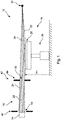
- Fig. 1 shows an example of the X-ray imaging apparatus 10 in a schematic setup.
- the X-ray imaging apparatus 10 comprises a source 12, a detector 14, an object-receiving space 16 and an X-ray radiation modulation arrangement 18.
- the source 12 is configured for generating X-ray radiation.
- the detector 14 is configured for detecting X-ray radiation.
- the object-receiving space 16 is configured for arranging an object of interest (not shown) for X-ray imaging.
- the X-ray radiation modulation arrangement 18 is configured for modulating X-ray radiation, in particular with respect to its intensity.
- the X-ray radiation modulation arrangement 18 also relates to as "X-ray modulation arrangement", “modulation arrangement” or “modulator”.
- the object-receiving space 16 is arranged between the source 12 and the detector 14.
- the X-ray radiation modulation arrangement 18 is arranged between the source 12 and the object-receiving space 16.
- the X-ray radiation modulation arrangement 18 comprises at least one mirror 20 for modulating X-ray radiation by providing a total reflection of a part 22 of the X-ray radiation of the source 12 at the at least one mirror 20 in order to deflect the part 22 of the X-ray radiation towards the detector 14, such that in the region of the object-receiving space 16, X-ray radiation is provided in form of unreflected primary X-ray radiation 24 in combination with secondary X-ray radiation 26 by the total reflection.
- the X-ray radiation modulation arrangement 18 further comprises at least one actuator 28 to displace the at least one mirror 20 at least between a first position P1 and a second position P2.
- a ratio of an intensity of the secondary X-ray radiation 26 and an intensity of the primary X-ray radiation 24 is higher at the first position P1 of the at least one mirror 20 than at the second position P2 of the at least one mirror 20.
- the X-ray radiation provided to the object-receiving space 16 can be modulated in its intensity.
- the intensity of the secondary X-ray radiation 26 is therefore adjustable by the displacement of the at least one mirror 20.
- the at least one mirror 20 may be displaced to its respective first position P1, such that a higher intensity of the combination of the primary X-ray radiation 24 and the secondary X-ray radiation 26 is provided to the object-receiving space 16.
- the at least one mirror 20 can be displaced to its respective second position P2, such that the intensity of the X-ray radiation at the object-receiving space 16 is decreased.
- an angle of incidence of an X-ray radiation provided by the source 12 may be, at least in part, be larger than a critical angle.
- the X-ray radiation provided by the source 12 and striking a boundary of the at least one mirror 20 may be not or partly not totally reflected. Accordingly, the combination of the primary X-ray radiation 24 and the secondary X-ray radiation 26 has a lower common intensity.
- a lower intensity of the X-ray radiation provided to the object-receiving space 16 is provided.
- the intensity of the X-ray radiation provided to the object-receiving space 16 can be adjusted and thus being modulated.
- a displacement of the at least one mirror 20 can be performed.
- the intensity of the secondary X-ray radiation 26 depends on the position of the at least one mirror 20. Accordingly, by controlling the actuator 28, the intensity of the secondary X-ray radiation 26 at the object-receiving space 16 can be adjusted.
- the intensity of the X-ray radiation provided to the object-receiving space 16 can be modulated in its intensity.
- the source 12 is configured for generating X-ray radiation.
- the source 12 for generating X-ray radiation is of the kind, which is generally known in the state of the art.
- the source 12 is provided by a rigid X-ray source unit, in particular such as an X-ray source of a stationary or rotation kind.
- the source 12 is an X-ray tube or a ⁇ -emitter.
- the X-ray radiation provided by the source 12 has an energy between 10 keV and 40 keV.
- the source 12 comprises a wavelength filter, which is configured for suppressing X-ray radiation having a wavelength corresponding to the energy of less than 10 keV.
- the detector 14 for detecting X-ray radiation is of the kind, which is generally known in the state of the art.
- the detector 14 is configured to provide a detector signal corresponding to an intensity of an X-ray radiation detected.
- the detector 14 can be configured for providing the detector signal to another unit and/or for further purposes, in particular for imaging purposes.
- the object-receiving space 16 relates to a space designated for arranging an object of interest.
- the object of interest may be of a biological material.
- the object-receiving space 16 comprises an object support arrangement, for example a pair of pads to hold and temporarily fix a breast for X-ray examination purposes, in particular for screening purposes.
- an object support arrangement for example a pair of pads to hold and temporarily fix a breast for X-ray examination purposes, in particular for screening purposes.
- the object-receiving space 16 is arranged between the source 12 and the detector 14.
- the X-ray radiation provided by the source 12 can be categorized or theoretically divided into several parts of X-ray radiation. One of these parts of X-ray radiation can relate to the so-called primary part 30 of the X-ray radiation provided by the source 12.
- the X-ray radiation generated by the source 12 comprises at least a primary part 30 and a secondary part 22.
- the primary part 30 has a propagation direction directly towards the detector 14 for forming primary X-ray radiation 24.
- the secondary part 22 may have a propagation direction directly towards the at least one mirror 20 at its first position P1.
- the at least one mirror 20 is arranged at least in its first position P1 for totally reflecting radiation of the secondary part 22 towards the detector 14 for forming the secondary X-ray radiation 26.
- sum of the the primary X-ray radiation 24 and the secondary X-ray radiation 26 provide an effective added X-ray radiation.
- the modulation arrangement 18 is configured such that an enhanced radiation can be provided at the object-receiving space 16.
- the X-ray radiation source 12 may comprise further X-ray radiation parts, which may be directed in a direction other than to the detector 14 or to the at least one mirror 20 in its first position P1.
- the primary part 30 of X-ray radiation is (directly) directed to the object-receiving space 16, in particular without being reflected by the X-ray radiation modulation arrangement 18.
- the primary part 30 of the X-ray radiation forms the primary X-ray radiation 24 at the object-receiving space 16.
- the secondary part 22 of the X-ray radiation is (preferably directly) directed to the X-ray radiation modulation arrangement 18.
- the secondary part 22 of the X-ray radiation is totally reflected at the at least one mirror 20 of the X-ray radiation modulation arrangement 18 in order to deflect the secondary part 22 of the X-ray radiation towards the detector 14, the reflected secondary part 22 of the X-ray radiation forms a secondary X-ray radiation 26 when reaching the object-receiving space 16.
- only a part of the secondary part 22 of the X-ray radiation is totally reflected at the at least one mirror 20 of the X-ray radiation modulation arrangement 18. This may occur, in case the at least one mirror is at its second position P2 or at another position between the first position P1 and the second position P2.
- the at least one mirror 20 preferably relates to a plate with a suitable low atomic number mirror material, in particular with an atomic number lower than nine.
- the at least one mirror 20 relates to a plate of a glass-ceramic.
- the at least one mirror 20 comprises a lithium aluminosilicate glass-ceramic.
- a mirror of that kind may have a specific density of 2.53. However, this is just one example for the specific density. Generally, a wide range of possible materials with specific densities for the at least one mirror 20 is possible.
- total reflection occurs at the at least one mirror 20 in case the at least one mirror has, with respect to the X-ray radiation, an optically thinner medium at a boundary surface to the space between the source 4 and the at least one mirror 20. Since refractive indices in the X-ray radiation regime are usually smaller than 1, an X-ray total reflection can be observed upon grazing incidents on any material given the incidence occurs within the critical angle of incidence ⁇ c .
- critical angle of incidence can also be referred to as "critical angle”.
- the critical angle ⁇ c is typically in the order of a few mrad (milli-rad).
- the critical angle ⁇ c may be between 0.5 mrad and 2 mrad.
- the density of the material being used for the at least one mirror 20 has to be increased, or metallic coating can be used, for example with silver or gold.
- the density of the material being used for the at least one mirror 20 has to be decreased.
- the at least one mirror 20 may comprises at least one plastic mirror layer, preferably having low atomic number element.
- total reflection refers to a reflection of an X-ray radiation wave, which strikes a boundary of a medium at an angle ⁇ i smaller than a particular critical angle ⁇ c with respect to a plane level to the boundary.
- the critical angle ⁇ c is the angle of incidence below which the total reflection occurs.
- the X-ray radiation provided to the object-receiving space 16 relates to a combination of the primary X-ray radiation 24 and the secondary X-ray radiation 26.
- An interference in the primary X-ray radiation 24 and the secondary X-ray radiation 26 may occur.
- the combination of the primary X-ray radiation 24 and the secondary X-ray radiation 26 leads to a superposition of the primary X-ray radiation 24 and the secondary X-ray radiation 26.
- the X-ray imaging apparatus 10 is configured for providing a combination of the primary X-ray radiation 24 and the secondary X-ray radiation 26 to the object-receiving space 16, an increase of total flux of X-ray radiation provided to the object-receiving space 16 may occur. Consequently, the X-ray imaging apparatus 10 is a cost-efficient improvement for adjusting the intensity of X-ray radiation being used for imaging an object of interest in the object-receiving space 16.
- the increase of the total flux of X-ray radiation at the object-receiving space 16 can be useful in case the object-receiving space is provided with an object of interest having a large thickness or a high density.
- the object-receiving space 16 is provided with an object of interest having a low thickness or a low density.
- an increase of the total flux of the X-ray radiation may not be helpful or even increase an X-ray radiation dose to object of interest without increasing an image quality of the object of interest.
- the X-ray radiation modulation arrangement 18 is configured for adjusting the intensity of the secondary X-ray radiation 26.
- the occurrence of total reflection at the at least one mirror 20 depends on the angle of incidence ⁇ i of an X-ray radiation wave striking a boundary of the at least one mirror 20.
- an X-ray radiation flux of the X-ray radiation being reflected at the at least mirror 20 can be controlled.
- the primary part 22 of the X-ray radiation provided by the source 12 is reflected at the at least one mirror 20 towards the detector 14, in case the at least mirror 20 is at its first position P1.
- the X-ray radiation flux of the secondary X-ray radiation 26 decreases, since an angle of incidence ⁇ i of the secondary part 22 at the at least one mirror 20 increases.
- only a part of the secondary part 22 of the X-ray radiation provided by the source 12 is totally reflected at the at least mirror 20 and thus being deflected to the detector 14.
- the angle of incidence ⁇ i of the secondary part 22 of the X-ray radiation provided by the source 12 is higher than a critical angle ⁇ c , the secondary part 22 of the X-ray radiation striking the at least one mirror 20 will not be reflected.
- the angle of incidence ⁇ i of the secondary part 22 of the X-ray radiation of the source 12 striking the at least one mirror 20 depends on the position of the at least one mirror. 20.
- a translational and/or a rotary displacement of the at least one mirror 20 has a influence on the angle of incidence ⁇ i .
- the at least one actuator 28 of the X-ray radiation modulation arrangement 18 is configured to displace the at least one mirror 20, the intensity of the secondary X-ray radiation 22 is preferably controllable by controlling the at least one actuator 28.
- the displacement of the at least one mirror 20 relates to a translational and/or a rotatory displacement.
- the at least one mirror 20 can be displaced linearly.
- the at least one mirror 20 can be displaced between its first position and its second position along a trajectory.
- the X-ray radiation modulation arrangement 18 comprises a mechanical guidance for the at least one mirror 20.
- the at least one actuator 28 can be configured to displace the at least one mirror 20 along a displacement-axis, wherein the displacement-axis and a longitudinal axis between the source 12 and the detector 14 form a angle between 45° and 135°, in particular between 60° and 120°, preferably between 85° and 95°. Accordingly, the at least one mirror 20 can be displaced for example perpendicular to the longitudinal axis.
- a simple structured actuator 28 can be used for the displacement of the at least one mirror 20.
- the at least one mirror 20 is configured for a continuous displacement between the first position P1 of the at least one mirror 20 and the second position P2 of the at least one mirror 20.
- the intensity of the secondary X-ray radiation 26 may change with the displacement continuously from a maximum intensity to a minimum intensity, or vice versa.
- the minimum intensity can be zero.
- the at least one mirror 20 is displaceable between three, four, five, six, seven, eight, or more positions, in particular between the first position P1 of the at least one mirror 20 and the second position P2 of the at least one mirror 20.
- Fig. 2 shows a schematic setup of a further example of the X-ray imaging apparatus 10.
- this example of the X-ray imaging apparatus 10 corresponds to the previously explained example of the X-ray imaging apparatus 10. Accordingly, reference is made to the explanation with respect to Fig. 1 .
- the secondary part 22 of the X-ray radiation provided by the source 12 is representatively shown in a line directed from the source 12 to the mirror 20.
- the at least one mirror 20 is at its first position P1.
- the angle of incidence ⁇ i1 is an angle between the secondary part 22 of the X-ray radiation provided by the source 12 and a plane surface of the at least one mirror 20.
- the angle of incidence ⁇ i1 is smaller than a critical angle ⁇ c . Therefore, total reflection occurs on the surface of the at least one mirror 20 with respect to the secondary part 22 of the X-ray radiation provided by the source 12.
- the reflected X-ray radiation will be deflected to the detector 14 and forming the secondary X-ray radiation 26 in the object-receiving space 16.
- the primary X-ray radiation 24 at the object-receiving space 16 and the secondary X-ray radiation 26 at the object-receiving space 16 are superposing each other, and thus enhancing the X-ray radiation provided to the object-receiving space 16.
- This enhancement increases the intensity of the X-ray radiation provided to the object-receiving space 16.
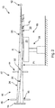
- Fig. 3 shows an alternative schematic setup of the previously explained example of the X-ray imaging apparatus 10, wherein the at least one mirror 20 is in a second position P2.
- the at least one actuator 28 is configured to displace the at least one mirror 20, preferably in a direction perpendicular to the longitudinal axis A between the source 12 and the detector 14. Accordingly, the at least one actuator 28 can displace the at least one mirror 20 linearly between the first position P1 and the second position P2.
- the displacement of the at least one mirror 20 changes the angle of incidence ⁇ i of the secondary part 22 of the X-ray radiation provided by the source 12 at the at least one mirror 20.
- the angle of incidence ⁇ i has been increased to ⁇ i2, such that the angle of incidence ⁇ i2 is larger than a critical angle ⁇ c. Accordingly, the secondary part 22 of the X-ray radiation provided by the source 12 is not totally reflected when striking upon a surface of the at least one mirror 20.
- Fig. 3 exemplarily shows that a displacement of the at least one mirror 20 may result in a decrease of the intensity of the X-ray radiation provided at the object-receiving space 16.
- the intensity of the X-ray radiation provided to the object-receiving space 16 is formed (in this case) solely by the primary X-ray radiation 24.
- the secondary part 22 of the X-ray radiation provided by the source 12 is not reflected and cannot contribute in this case to the intensity of the X-ray radiation at the object receiving space 16.
- the intensity of the secondary X-ray radiation 26 may not be zero, but less with respect to the case, when the at least one mirror 20 is at its first position P1.
- the modulation of the X-ray radiation at the object-receiving space 16 relates to the intensity of the secondary X-ray radiation 26 at the object-receiving space 16.
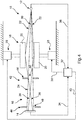
- Fig. 4 shows a schematic setup of a further example of the imaging apparatus 10.
- the imaging apparatus 10 is similar to the imaging apparatuses 10 explained with respect to the Figs. 1 to 3 . Thus, reference is made to the previous explanations, where suitable.
- the imaging apparatus 10 comprises a control unit 32 for determining an attenuation of the intensity of the X-ray radiation in form of a combination of the primary X-ray radiation 24 and of the secondary X-ray radiation 26 at the object-receiving space 16 and for controlling the modulation arrangement 18 depending on the attenuation.
- the intensity X-ray radiation provided to the object-receiving space 16 can be adjusted to the density and/or thickness of an object of interest arranged at the object receiving space 16.
- the intensity of the X-ray radiation at the object receiving space 16 can be increased by the control unit 32.
- the control unit 32 may control a displacement of the at least one mirror 20, such that the secondary X-ray radiation 26 superposes the primary X-ray radiation 24.
- a higher common intensity is provided.
- the X-ray imaging apparatus 10 is configured, such that control unit 32 receives a signal from the detector 14, whereas the signal is representative for the X-ray radiation detected.
- a signal line 34 between the detector 14 and the control unit 32 is provided.
- the X-ray imaging apparatus 10 is configured, such that the control unit 32 receives a signal from the source 12 wherein the signal of the source 12 is representative of the X-ray radiation provided to the modulation arrangement 18, especially to its at least one mirror 20, and/or directly to the detector 14.
- a signal line 36 between the source 12 and the control unit 32 is provided.
- control unit 32 is configured to receive signals from the detector 14 and the source 12, wherein on the basis of the signals, an attenuation of the X-ray radiation at the object-receiving space 16 can be determined by the control unit 32.
- control unit 32 is configured to control at least one actuator 28.
- a signal line 38, 40 between the control unit 32 and the at least one actuator 28 is provided.
- control unit 32 received signals, which represent the intensity of the X-ray radiation provided by the source 12 and an intensity of the X-ray radiation impinging the detector 14, the control unit 32 can be configured to determine the attenuation of the X-ray radiation provided to the object receiving space 16.
- the X-ray imaging apparatus 10 shown in Fig. 4 comprises two mirrors 20.
- Each of the actuators 28 is connected via a respective control signal line 38, 40 with the control unit 32.
- the control unit 32 can adjust, in particular in accordance with the attenuation of the primary X-ray radiation 24 and/or the attenuation of the secondary X-ray radiation 26, a displacement of the mirrors 20 by controlling the actuators 28.
- the X-ray imaging apparatus 10 comprises a sensor (not shown) configured to detect a spatial parameter of an object of interest.
- the sensor can be configured for detecting a lateral extension of an object of interest and/or a thickness of an object of interest.
- control unit 32 is configured for controlling the modulation arrangement 18 depending, in particular also, on the spatial parameter detected by the sensor.
- the control unit 32 can control the at least one actuator 28 depending on a lateral extension and/or a thickness of an object of interest, which has been arranged at the object-receiving space 16.
- control unit 32 can adjust the intensity of the secondary X-ray radiation 26 in accordance with a detected lateral extension, a thickness or any other spatial parameter of an object of interest, which has been arranged at the object-receiving space 16.
- Fig. 1 to Fig. 4 show that the at least one mirror 20 is preferably not in conflict with the primary part 30 of the X-ray radiation provided by the source 12.
- the at least one mirror 20 is arranged laterally to the primary part 30 of the X-ray radiation provided by the source 12.
- the primary part 30 of the X-ray radiation provided by the source 12 can reach the object-receiving space 16 unhindered, in order to form the primary X-ray radiation 24.
- the at least one mirror 20 is displaceable along a trajectory between its first position P1 and its second position P2.
- the trajectory of the at least one mirror 20 is arranged to intersect a propagation direction of the secondary part 22 of the X-ray radiation provided by the source 12. Further preferably, the trajectory of the at least one mirror 20 is outside a primary part 30 of the X-ray radiation provided by the source 12.
- the at least one mirror 20 can be displaced along its trajectory to a position, where a total reflection of at least a part of the secondary part 22 of the X-ray radiation provided by the source 12 occurs, such that the reflected X-ray radiation forms the secondary X-ray radiation 26 at the object-receiving space 16.
- the trajectory of the at least one mirror 20 and the propagation direction of the secondary part 22 of the X-ray radiation provided by the source 12 form an intersection angle of greater than 0.
- the intersection angle is between 80° and 110°.
- the modulation arrangement 18 is configured such that in the first position P1 of the at least one mirror 20, an incidence angle ⁇ i1 of the secondary part 22 of the X-ray radiation provided by the source 12 at the at least one mirror 20 is smaller than a critical angle ⁇ c of total reflection, and in the second position P2 of the at least one mirror 20, an incidence angle ⁇ i2 of the secondary part 22 of the X-ray radiation provided by the source 12 at the at least one mirror 20 is larger than a critical angle ⁇ c of total reflection.
- the respective angle of incidence ⁇ i2 is preferably larger than the critical angle ⁇ c, such that a secondary part 22 of the X-ray radiation of the source 12 is not totally reflected, and in particular being absorbed by the at least one mirror 20.
- the at least one mirror 20 comprises a concave reflecting-surface.
- a concave mirror surface may increase the intensity of reflected X-ray radiation.
- the imaging apparatus 10 preferably comprises a collimation arrangement 42.
- the imaging apparatus 10 comprises a collimation arrangement 42 between the source 12 and the detector 14.
- the collimation arrangement 42 comprises a pre-collimator 44 arranged between the mirror arrangement 18 and the object-receiving space 16, and a post-collimator 46 arranged between the object-receiving space 16 and the detector 14.
- collimated X-ray radiation is provided to the object-receiving space 16 by the pre-collimator 44.
- collimated X-ray radiation is provided to the detector 14 by the post-collimator 46.
- the pre-collimator 44 relates to an optical element comprising at least one aperture 50.
- each aperture 50 of the pre-collimator 44 is formed as a slit.
- the pre-collimator 44 is configured to provide collimated X-ray radiation.
- an X-ray radiation can pass the at least one aperture 50 of the pre-collimator 44 as a collimated X-ray beam.
- the post-collimator 46 relates to an optical element comprising at least one aperture 48.
- each aperture 48 of the post-collimator 46 can be formed as a slit.
- an X-ray radiation can pass the at least one aperture 48 of the post-collimator 46 as a collimated X-ray beam.
- Collimators 44, 46 are generally known in the state of the art.
- the pre-collimator 44 and/or the post-collimator 46 comprise each a plate, in particular an X-ray absorbing plate, with at least one hole, which may form an aperture 50, 48 of the respective collimator 44, 46.
- an X-ray radiation striking on the plate of the collimator 44, 46 outside the at least one aperture 48, 50 will not pass. Instead, this X-ray radiation will very likely be absorbed by the plate.
- the at least one aperture 50 of the pre-collimator 44 is configured to allow a transmission of the primary part 30 of the X-ray radiation provided by the source 12 and of a secondary part 22 of the X-ray radiation provided by the source 12 and being reflected at the at least one mirror 20. Accordingly, the at least one aperture 50 of the pre-collimator 44 is configured and/or arranged such that primary X-ray radiation 24 and/or secondary X-ray radiation 26 can be provided to the object-receiving space 16.
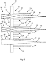
- Fig. 5 shows a further example of the pre-collimator 44 and a further example of the modulation arrangement 18.
- the pre-collimator 44 comprises a plurality of pre-collimator apertures 50 for providing a plurality of X-ray beams 52 to the object-receiving space 16.
- the pre-collimator 44 is arranged between the modulation arrangement 18 and the object-receiving space 16.
- the modulation arrangement 18 comprises for each pre-collimator aperture 50 at least one associated mirror 20 of the at least one mirror 20.
- the X-ray beams 52 are formed by primary X-ray radiation 24 and the secondary X-ray radiation 26. Accordingly, the X-ray beams 52 can form the X-ray radiation at the object-receiving space 16.
- the primary part 30 of the X-ray radiation is provided by the same source 12.
- the associated mirror 20 can be replaced with an associated group 54a, 54b, 54c of two mirrors 20 for deflecting the secondary part 22 of the X-ray radiation provided by the source 12 to the associated pre-collimator aperture 50 in order to form the secondary X-ray radiation 26 in form of the X-ray beams 52.
- the mirrors 20 of a first group 54a are in its first position P1. Accordingly, total reflection of the secondary part 22 of the X-ray radiation of the source 12 occurs.
- the mirrors 20 of a second group 54b are in a position between its possible first position P1 and its possible second position P2. Accordingly, total reflection of the secondary part 22 of the X-ray radiation of the source 12 occurs partly.
- the mirrors 20 of a third group 54c are in its second position P2. Accordingly, total reflection of the secondary part 22 of the X-ray radiation of the source 12 does not occur. In this case, the X-ray radiation beam 52 provided to the object receiving space 16 is formed by the primary X-ray radiation 24 only.
- a group 54a, 54b, 54c of at least two mirrors 20 of the mirror arrangement 18 and an actuator 28 are provided.
- each mirror 20 of the modulation arrangement 18 is coupled to one of the actuators 28 of the plurality of actuators 28. Further preferably, each mirror 20 is independently displaceable by its coupled actuator 28.
- each mirror 20 of the modulation arrangement 18 can be displaced individually between its first position P1 and its second position P2. Further positions for each of the mirrors 20 can be provided, where the coupled actuator 28 can displace the respective mirror 20 at. As a result, the intensity of the X-ray beams 52 can be individually controlled.
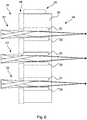
- Fig. 6 shows a part of an exemplary embodiment of the modulation arrangement 18.
- the modulation arrangement 18 comprises a plurality of actuators 28.
- a coupling element 56 is provided, which is configured to couple the actuator 28 with the group 54 of the at least two mirrors 20.
- the mirrors 20 of the group 54 are commonly displaced and thus having a similar influence on the reflection of the secondary part 22 of the X-ray radiation provided by the source 12.
- one or several X-ray beams 52 provided by the pre-collimator 44 can be controlled commonly in its intensity.
- a modulation of one or several beams 52 can be performed with the same actuator 28.
- the modulation arrangement 18 comprises at least two actuators 28, wherein each of the actuators 28 are coupled to a group of at least four or at least six mirrors 20 of the modulation arrangement 18.
- the number of actuators 28 needed for controlling the displacement of a plurality of mirrors 20 can be reduced while keeping the possibility to modulate the X-ray radiation provided to the object-receiving space 16 differently for different areas of the object-receiving space 16.
- the modulation arrangement 18 comprises at least ten actuators 28.
- the X-ray radiation intensity applied to an object of interest can be locally adapted, for instance to an attenuation of the X-ray radiation provided to the object of interest and/or its local density and/or its local thickness.
- Fig. 7 shows a schematic setup of a part of the imaging apparatus 10 comprising a control unit 32 and a detector arrangement 58.
- the modulation arrangement 18 comprises a plurality of actuators 28.
- Each actuator 28 of the modulation arrangement 18 is coupled to a group 54 of at least two mirrors 20 of the modulation arrangement 18. Further, each group 54 of the mirrors 20 is commonly displaceable by the coupled actuator 28.
- a post-collimator 46 is provided that comprises for each aperture 50 of the pre-collimator 44 an associated post-collimator aperture 48.
- a detector arrangement 58 is provided, that comprises a plurality of detectors 14.
- the post-collimator 46 is arranged between the object-receiving space 16 and the detector arrangement 58.
- one of the detectors 14 is associated and arranged for detecting X-ray radiation passing the respective aperture 48 of the post-collimator 46, such that an aperture-dependent detector signal is provided.
- a control unit 32 is provided to control, based on the aperture-dependent detector signal, an individual displacement of the mirrors 20 or a displacement in groups 54a, 54b, 54c of at least two mirrors 20.
- an associated group 54a, 54b, 54c of at least two mirrors 20 is provided for each aperture 50 of the pre-collimator 44.
- the respective group 54a, 54b, 54c of the at least two mirrors 20 can be arranged in order to influence the reflection of the secondary part 22 of the X-ray radiation provided by the source 12, which is directed to the respective aperture 50 of the pre-collimator 44.
- the intensity of the X-ray radiation provided to the object-receiving space 16 can be controlled locally in form of an intensity of each beam 52.
- a group 54a, 54b, 54c comprises more than two mirrors 20, for example four mirrors or six mirrors. Accordingly, more than one beam 52, for example two or three beams 52, can be controlled commonly. As a result, the number of actuators 28 can be reduced.
- an associated detector 14 is provided for each aperture 48 of the post-collimator 46.
- the signal provided by each detector 14 preferably corresponds to the X-ray radiation detected.
- the control unit 32 is connected to each detector 14 via a signal line 34.
- the control unit 32 can receive the signals of the detectors 14 in order to determine the attenuation of each beam 52.
- the control unit 32 can evaluate the signals provided by the detectors 14 and determine a control signal for the actuators 28, such that a suitable attenuation of the X-ray radiation provided to the object-receiving space 16 is reached. In a example, a uniform attenuation at the object receiving space 16 may be aimed.
- the at least one mirror 20 abutting to one of the apertures 50 of the pre-collimator 44 is controlled by the control unit 32 depending on the detector signal of the detector 14 associated with the aperture 48 of the post-collimator 46, wherein this aperture 48 of the post-collimator 46 is associated with the aforementioned aperture 50 of the pre-collimator 44.
- an aperture 50 of the pre-collimator and an aperture 48 of the post-collimator 46 can form a group with at least one associated detector 14, at least one associated mirror 20 and at least one associated actuator 28.
- the control unit 32 can control the modulation arrangement 18 groupwise.
- Fig. 8 shows an example of a slit arrangement 60.
- each aperture 50 of the pre-collimator 44 is formed as a slit.
- each aperture 48 of the post-collimator 46 is formed as a slit.
- the pre-collimator 44 is formed as a pre-collimator slit arrangement.
- the post-collimator 46 is formed as a post-collimator slit arrangement.
- slit arrangement can refer to pre-collimator slit arrangement and/or the post-collimator slit arrangement.
- the slit arrangement 60 comprises a plurality of slits 62.
- a subgroup of the plurality of slits 62 are arranged parallel to an extension direction of the slits 62.
- a further subgroups of the slits 62 are arranged in the extension direction of the slits 62 one after another with a separating space between adjacent slits 62.
- an X-ray imaging system (not shown) is provided.
- the X-ray imaging system comprises an imaging apparatus 10 according to one of the preceding examples described.
- the X-ray imaging system further comprises an imaging processing unit and an image data output unit.
- the imaging processing unit is configured to receive signals from the detector 14 or the detector arrangement 58 and to compute image data of an object based on the signals.
- the image data output unit is configured to provide the image data for further purpose.
- the data output unit is a display for showing the image data.
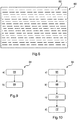
- Fig. 9 shows a method 64 for modulating of X-ray radiation.
- the method 64 comprises the following: In a first generating step 66, also referred to as step a), X-ray radiation is generated and a primary part 30 of the X-ray radiation is unreflected directed as primary X-ray radiation 24 towards a detector 14.
- a secondary part 22 of the X-ray radiation is reflected with a mirror 20.
- step b) the reflecting is provided as total reflection of the secondary part 22 of the X-ray radiation in order to deflect the secondary part 22 of the X-ray radiation as secondary X-ray radiation 26 towards the detector 14.
- step b) comprises a displacing of the mirror 20 at least between a first position P1 and a second position P2.
- a ratio of an intensity of the secondary X-ray radiation 26 to an intensity of the primary X-ray radiation 24 is higher at the first position P1 of the mirror 20 than in the second position P2 of the mirror 20.
- the part 22 of X-ray radiation provided towards the detector 14 can be controlled by a displacement of the at least one mirror 20.
- the part 22 of the X-ray radiation directed towards the detector 14 can be modulated.
- the modulated X-ray radiation is detected.
- the method 64 further comprises the following:
- a third determining step 70 also referred to as step c) an attenuation of the intensity of the X-ray radiation in form of the combination of the primary X-ray radiation 24 and the secondary X-ray radiation 26 at the object-receiving space 16 is determined.
- step d the modulation is controlled depending on the attenuation.
- a plurality of modulator-detector-pairs is provided, each comprising a mirror 20 for reflecting the X-ray radiation in step b) and an associated detector 14.
- each mirror 20 is controlled individually depending on the attenuation of the intensity of the primary X-ray radiation 24 and/or the secondary X-ray radiation 26 at the object-receiving space 16 determined with the associated detector 14.
Landscapes
- Health & Medical Sciences (AREA)
- Life Sciences & Earth Sciences (AREA)
- Engineering & Computer Science (AREA)
- Medical Informatics (AREA)
- Pathology (AREA)
- General Health & Medical Sciences (AREA)
- Physics & Mathematics (AREA)
- Heart & Thoracic Surgery (AREA)
- Biophysics (AREA)
- Nuclear Medicine, Radiotherapy & Molecular Imaging (AREA)
- Radiology & Medical Imaging (AREA)
- Biomedical Technology (AREA)
- High Energy & Nuclear Physics (AREA)
- Molecular Biology (AREA)
- Surgery (AREA)
- Animal Behavior & Ethology (AREA)
- Optics & Photonics (AREA)
- Public Health (AREA)
- Veterinary Medicine (AREA)
- Chemical & Material Sciences (AREA)
- Analytical Chemistry (AREA)
- Biochemistry (AREA)
- General Physics & Mathematics (AREA)
- Immunology (AREA)
- Apparatus For Radiation Diagnosis (AREA)
- Analysing Materials By The Use Of Radiation (AREA)
- X-Ray Techniques (AREA)
Claims (10)
- Appareil d'imagerie avec des rayons X (10), comprenant :- une source (12) pour générer un rayonnement de rayons X ;- un détecteur (14) pour détecter un rayonnement de rayons X ;- un espace de réception d'objet (16) pour agencer un objet d'intérêt pour une imagerie avec des rayons X ;- un agencement de modulation du rayonnement de rayons X (18) ;
dans lequel l'espace de réception d'objet est agencé entre la source et le détecteur ;
dans lequel l'agencement de modulation du rayonnement de rayons X est agencé entre la source et l'espace de réception d'objet ;
dans lequel l'agencement de modulation du rayonnement de rayons X comprend au moins un miroir (20) pour moduler le rayonnement de rayons X en fournissant une réflexion totale d'une partie du rayonnement de rayons X de la source au niveau de l'au moins un miroir afin de dévier la partie (22) du rayonnement de rayons X vers le détecteur, de telle manière que dans la région de l'espace de réception d'objet le rayonnement de rayons X est fourni sous la forme d'un rayonnement de rayons X primaire non réfléchi (24) en combinaison avec un rayonnement de rayons X secondaire (26) par la réflexion totale ; et- une unité de commande pour déterminer une atténuation de l'intensité du rayonnement de rayons X sous la forme de la combinaison du rayonnement de rayons X primaire et du rayonnement de rayons X secondaire au niveau de l'espace de réception d'objet et pour commander l'agencement de modulation en fonction de l'atténuation ;dans lequel l'agencement de modulation du rayonnement de rayons X comprend en outre au moins un actionneur (28) pour déplacer l'au moins un miroir au moins entre une première position P1 et une seconde position P2 ;
dans lequel un rapport d'une intensité du rayonnement de rayons X secondaire à une intensité du rayonnement de rayons X primaire est plus élevé au niveau de la première position de l'au moins un miroir qu'au niveau de la seconde position de l'au moins un miroir ;
dans lequel est en outre fourni un agencement de collimation (42) entre la source et le détecteur ; et
dans lequel l'agencement de collimation comprend un pré-collimateur (44) qui comprend une pluralité d'ouvertures de pré-collimateur (50) pour fournir une pluralité de faisceaux de rayons X (52) à l'espace de réception d'objet ; dans lequel le pré-collimateur est agencé entre l'agencement de modulation et l'espace de réception d'objet ; et dans lequel l'agencement de modulation comprend pour chaque ouverture de pré-collimateur au moins un miroir associé de l'au moins un miroir. - Appareil selon la revendication 1, dans lequel le rayonnement de rayons X généré par la source comprend au moins une partie primaire (30) et une partie secondaire (22), dans lequel la partie primaire a une direction de propagation directement vers le détecteur pour former le rayonnement de rayons X primaire, dans lequel la partie secondaire a une direction de propagation vers l'au moins un miroir dans sa première position ; dans lequel l'au moins un miroir est agencé au moins dans sa première position pour totalement réfléchir le rayonnement de la partie secondaire vers le détecteur pour former le rayonnement de rayons X secondaire ; et dans lequel, pour irradier un objet d'intérêt, la somme du rayonnement de rayons X primaire et du rayonnement de rayons X secondaire fournit un rayonnement de rayons X additionné efficace.
- Appareil selon la revendication 2, dans lequel l'au moins un miroir est agencé latéralement par rapport à la partie primaire du rayonnement de rayons X fourni par la source.
- Appareil selon l'une des revendications 1 à 3, dans lequel l'agencement de collimation comprend en outre un post-collimateur (46) agencé entre l'espace de réception d'objet et le détecteur.
- Appareil selon la revendication 1, dans lequel l'agencement de modulation comprend une pluralité des actionneurs ; dans lequel chaque miroir de l'agencement de modulation est couplé à l'un des actionneurs de la pluralité d'actionneurs ; et dans lequel chaque miroir est indépendamment déplaçable par l'actionneur couplé.
- Appareil selon la revendication 1, dans lequel l'agencement de modulation comprend une pluralité des actionneurs ; dans lequel chaque actionneur de l'agencement de modulation est couplé à un groupe d'au moins deux miroirs de l'agencement de modulation ; et dans lequel chaque groupe des miroirs est déplaçable mutuellement par l'actionneur couplé.
- Appareil selon la revendication précédente, dans lequel un post-collimateur est fourni qui comprend pour chaque ouverture du pré-collimateur une ouverture de post-collimateur associée ; dans lequel un agencement de détecteurs est fourni, qui comprend une pluralité de détecteurs ; dans lequel le post-collimateur est agencé entre l'espace de réception d'objet et l'agencement de détecteurs ; dans lequel pour chaque ouverture du post-collimateur l'un des détecteurs est associé et agencé pour détecter un rayonnement de rayons X passant par l'ouverture respective du post-collimateur, de telle manière qu'un signal de détecteur dépendant de l'ouverture est fourni ; et dans lequel une unité de commande est fournie pour commander, sur la base du signal de détecteur dépendant de l'ouverture, un déplacement individuel des miroirs ou un déplacement dans les groupes d'au moins deux miroirs.
- Appareil selon l'une des revendications précédentes 1, 5, 6 ou 7, dans lequel le pré-collimateur se présente sous la forme d'un agencement de fentes de collimateur.
- Système d'imagerie avec des rayons X, comprenant :- un appareil selon l'une des revendications précédentes,- une unité de traitement d'imagerie ; et- une unité de sortie de données d'image ;dans lequel l'unité de traitement d'imagerie est configurée pour recevoir des signaux à partir du détecteur ou de l'agencement de détecteurs et pour calculer des données d'image d'un objet sur la base des signaux ; et
dans lequel l'unité de sortie de données d'image est configurée pour fournir les données d'image à des fins ultérieures. - Procédé (64) de modulation de rayonnement de rayons X, comprenant les étapes suivantes :a) génération (66) d'un rayonnement de rayons X et direction d'une partie primaire du rayonnement de rayons X sous la forme d'un rayonnement de rayons X primaire non réfléchi vers un détecteur ; etb) réflexion (68) d'une partie secondaire du rayonnement de rayons X avec un miroir ;
dans lequel dans l'étape b), la réflexion est fournie sous la forme d'une réflexion totale de la partie secondaire du rayonnement de rayons X afin de dévier la partie secondaire du rayonnement de rayons X en tant que rayonnement de rayons X secondaire vers le détecteur ;
dans lequel pour une modulation du rayonnement de rayons X, l'étape b) comprend un déplacement du miroir au moins entre une première position et une seconde position ; et
dans lequel un rapport d'une intensité du rayonnement de rayons X primaire à une intensité du rayonnement de rayons X secondaire est plus élevé dans la première position du miroir que dans la seconde position du miroir ;
dans lequel est en outre fournie :
une détection du rayonnement de rayons X modulé ;c) détermination (70) d'une atténuation de l'intensité du rayonnement de rayons X d'une combinaison du rayonnement de rayons X primaire et du rayonnement de rayons X secondaire à l'intérieur de l'espace de réception d'objet ; etd) commande (72) de la modulation en fonction de l'atténuation ; etdans lequel une pluralité de paires modulateur-détecteur est fournie, chacune comprenant un miroir pour la réflexion du rayonnement de rayons X dans l'étape b) et un détecteur associé,
dans lequel pour la modulation chaque miroir est commandé individuellement en fonction de l'atténuation de l'intensité du rayonnement de rayons X primaire et/ou du rayonnement de rayons X secondaire à l'intérieur de l'espace de réception d'objet déterminé avec le détecteur associé.
Applications Claiming Priority (2)
| Application Number | Priority Date | Filing Date | Title |
|---|---|---|---|
| EP15176597 | 2015-07-14 | ||
| PCT/EP2016/066596 WO2017009363A1 (fr) | 2015-07-14 | 2016-07-13 | Imagerie avec rayonnement de rayons x modulé |
Publications (2)
| Publication Number | Publication Date |
|---|---|
| EP3322341A1 EP3322341A1 (fr) | 2018-05-23 |
| EP3322341B1 true EP3322341B1 (fr) | 2019-03-27 |
Family
ID=53541613
Family Applications (1)
| Application Number | Title | Priority Date | Filing Date |
|---|---|---|---|
| EP16738759.6A Not-in-force EP3322341B1 (fr) | 2015-07-14 | 2016-07-13 | Imagerie par rayons x modulés |
Country Status (5)
| Country | Link |
|---|---|
| US (1) | US10925556B2 (fr) |
| EP (1) | EP3322341B1 (fr) |
| JP (1) | JP6545353B2 (fr) |
| CN (1) | CN107847201B (fr) |
| WO (1) | WO2017009363A1 (fr) |
Families Citing this family (2)
| Publication number | Priority date | Publication date | Assignee | Title |
|---|---|---|---|---|
| EP3603516A1 (fr) * | 2018-08-02 | 2020-02-05 | Siemens Healthcare GmbH | Dispositif à rayons x et procédé de fonctionnement du dispositif à rayons x |
| KR20210109304A (ko) * | 2020-02-27 | 2021-09-06 | 주식회사 에이치디엑스윌 | 동적 제어가 가능한 콜리메이터를 구비한 콘빔 ct 장치 |
Family Cites Families (35)
| Publication number | Priority date | Publication date | Assignee | Title |
|---|---|---|---|---|
| US4242588A (en) * | 1979-08-13 | 1980-12-30 | American Science And Engineering, Inc. | X-ray lithography system having collimating optics |
| US5077774A (en) * | 1989-07-12 | 1991-12-31 | Adelphi Technology Inc. | X-ray lithography source |
| US6031892A (en) * | 1989-12-05 | 2000-02-29 | University Of Massachusetts Medical Center | System for quantitative radiographic imaging |
| EP0498908A1 (fr) * | 1991-02-13 | 1992-08-19 | Siemens Aktiengesellschaft | Ecran d'enregistrement luminescent contenant un produit luminescent d'enregistrement stimulable |
| US5268951A (en) | 1992-12-22 | 1993-12-07 | International Business Machines Corporation | X-ray beam scanning method for producing low distortion or constant distortion in x-ray proximity printing |
| JP3078168B2 (ja) * | 1994-02-28 | 2000-08-21 | 三菱電機株式会社 | 電磁波検出装置及び基板加工装置 |
| US5757882A (en) * | 1995-12-18 | 1998-05-26 | Osmic, Inc. | Steerable x-ray optical system |
| GB9920327D0 (en) | 1999-08-28 | 1999-11-03 | Koninkl Philips Electronics Nv | Menu display for a graphical user interface |
| DE10236640B4 (de) * | 2002-08-09 | 2004-09-16 | Siemens Ag | Vorrichtung und Verfahren zur Erzeugung monochromatischer Röntgenstrahlung |
| US6917667B2 (en) * | 2002-09-03 | 2005-07-12 | Rigaku Corporation | Method and apparatus for making parallel X-ray beam and X-ray diffraction apparatus |
| KR100576921B1 (ko) * | 2003-01-15 | 2006-05-03 | 한국원자력연구소 | 고광도의 평행빔 생성 장치 |
| DE10322137A1 (de) * | 2003-05-16 | 2004-12-16 | Siemens Ag | Röntgengerät mit verbesserter Effizienz |
| US7068754B2 (en) | 2003-06-30 | 2006-06-27 | Siemens Medical Solutions Usa, Inc. | System to generate therapeutic radiation |
| US7339170B2 (en) * | 2003-07-16 | 2008-03-04 | Shrenik Deliwala | Optical encoding and reconstruction |
| JP2007529738A (ja) * | 2004-03-17 | 2007-10-25 | コーニンクレッカ フィリップス エレクトロニクス エヌ ヴィ | 干渉性散乱ctのビーム硬化補正および減衰補正 |
| US7330535B2 (en) * | 2005-11-10 | 2008-02-12 | General Electric Company | X-ray flux management device |
| DE102006015933B3 (de) * | 2006-04-05 | 2007-10-31 | Incoatec Gmbh | Vorrichtung und Verfahren zum Justieren eines optischen Elements |
| CN101689466B (zh) | 2007-06-21 | 2014-06-04 | 皇家飞利浦电子股份有限公司 | 利用旋转阳极或旋转帧管中的z偏转进行的快速剂量调制 |
| US20090041198A1 (en) * | 2007-08-07 | 2009-02-12 | General Electric Company | Highly collimated and temporally variable x-ray beams |
| US7742566B2 (en) * | 2007-12-07 | 2010-06-22 | General Electric Company | Multi-energy imaging system and method using optic devices |
| JP4650642B2 (ja) * | 2007-12-13 | 2011-03-16 | 株式会社エーイーティー | X線発生装置 |
| EP2249704A4 (fr) * | 2008-01-30 | 2013-07-03 | Reflective X Ray Optics Llc | Monture de miroir, mécanisme d'alignement et de balayage, procédé de balayage pour imagerie radiographique par rayons x, et dispositif d'imagerie par rayons x comportant ces éléments |
| WO2010051469A1 (fr) | 2008-10-30 | 2010-05-06 | Kenneth Oosting | Processeur de faisceaux de rayons x |
| JP4868034B2 (ja) * | 2009-07-16 | 2012-02-01 | 横河電機株式会社 | 放射線検査装置 |
| JP4919115B2 (ja) * | 2009-09-24 | 2012-04-18 | 横河電機株式会社 | 放射線検査装置 |
| JP2013509684A (ja) * | 2009-10-28 | 2013-03-14 | コーニンクレッカ フィリップス エレクトロニクス エヌ ヴィ | X線発生装置のアノード電位の切り替え |
| JP4911373B2 (ja) * | 2009-11-26 | 2012-04-04 | 横河電機株式会社 | X線測定装置 |
| JP2011112561A (ja) * | 2009-11-27 | 2011-06-09 | Yokogawa Electric Corp | X線測定装置 |
| JP4883378B2 (ja) * | 2009-12-22 | 2012-02-22 | 横河電機株式会社 | 放射線検出装置 |
| JP2011164043A (ja) * | 2010-02-15 | 2011-08-25 | Yokogawa Electric Corp | X線装置 |
| DE102010022851B4 (de) * | 2010-06-07 | 2014-11-13 | Siemens Aktiengesellschaft | Röntgenstrahlungsvorrichtung zur Erzeugung von quasimonochromatischer Röntgenstrahlung und Radiographie-Röntgenaufnahmesystem |
| US8311184B2 (en) * | 2010-08-30 | 2012-11-13 | General Electric Company | Fan-shaped X-ray beam imaging systems employing graded multilayer optic devices |
| US20130114795A1 (en) * | 2011-09-22 | 2013-05-09 | Canon Kabushiki Kaisha | X-ray waveguide, method for manufacturing x-ray waveguide, and method for controlling x-ray waveguide |
| US9117622B2 (en) | 2012-08-08 | 2015-08-25 | The United States Of America As Represented By The Administrator Of The National Aeronautics And Space Administration | Miniaturized high-speed modulated X-ray source |
| CN103234987B (zh) * | 2013-04-17 | 2015-06-03 | 同济大学 | 一种时间分辨的多色单能x射线成像谱仪 |
-
2016
- 2016-07-13 JP JP2018501245A patent/JP6545353B2/ja not_active Expired - Fee Related
- 2016-07-13 US US15/742,645 patent/US10925556B2/en active Active
- 2016-07-13 CN CN201680041160.8A patent/CN107847201B/zh not_active Expired - Fee Related
- 2016-07-13 EP EP16738759.6A patent/EP3322341B1/fr not_active Not-in-force
- 2016-07-13 WO PCT/EP2016/066596 patent/WO2017009363A1/fr active Application Filing
Non-Patent Citations (1)
| Title |
|---|
| None * |
Also Published As
| Publication number | Publication date |
|---|---|
| JP2018526064A (ja) | 2018-09-13 |
| EP3322341A1 (fr) | 2018-05-23 |
| CN107847201A (zh) | 2018-03-27 |
| WO2017009363A1 (fr) | 2017-01-19 |
| US20180192973A1 (en) | 2018-07-12 |
| US10925556B2 (en) | 2021-02-23 |
| JP6545353B2 (ja) | 2019-07-17 |
| CN107847201B (zh) | 2021-04-30 |
Similar Documents
| Publication | Publication Date | Title |
|---|---|---|
| US8208602B2 (en) | High flux photon beams using optic devices | |
| US9066649B2 (en) | Apparatus for phase-contrast imaging comprising a displaceable X-ray detector element and method | |
| JP5476315B2 (ja) | 光学アセンブリ、光学装置のアレイ、多重エネルギ・イメージング・システム及び方法 | |
| US9087619B2 (en) | Apparatus for scatter reduction for CT imaging and method of fabricating same | |
| US10082473B2 (en) | X-ray filtration | |
| JPS63501735A (ja) | 改良されたx線減衰方法および装置 | |
| US20160270198A1 (en) | X-ray imaging device with fast spatial modulation of photon flux | |
| EP3322341B1 (fr) | Imagerie par rayons x modulés | |
| KR102177991B1 (ko) | 레이저-콤프턴 엑스레이 소스를 이용한 2-컬러 방사선 촬영 방법들 | |
| US20070030947A1 (en) | X-ray device with improved efficiency | |
| JP5208224B2 (ja) | 放射線撮影装置、及び放射線撮影システム | |
| KR20080042767A (ko) | 영상화 단층 촬영 방법 및 장치 | |
| US20140185745A1 (en) | Collimator for use in a ct system | |
| EP3538879B1 (fr) | Imagerie à contraste de phase basé sur une réseau | |
| EP3322340B1 (fr) | Imagerie avec un rayonnement de rayons x amélioré | |
| JP4421327B2 (ja) | X線コリメータ及びx線撮像装置 | |
| JP2001037746A (ja) | 医学用放射光x線撮像装置 | |
| JP2003139724A (ja) | Ct装置 |
Legal Events
| Date | Code | Title | Description |
|---|---|---|---|
| STAA | Information on the status of an ep patent application or granted ep patent |
Free format text: STATUS: THE INTERNATIONAL PUBLICATION HAS BEEN MADE |
|
| PUAI | Public reference made under article 153(3) epc to a published international application that has entered the european phase |
Free format text: ORIGINAL CODE: 0009012 |
|
| STAA | Information on the status of an ep patent application or granted ep patent |
Free format text: STATUS: REQUEST FOR EXAMINATION WAS MADE |
|
| 17P | Request for examination filed |
Effective date: 20170816 |
|
| AK | Designated contracting states |
Kind code of ref document: A1 Designated state(s): AL AT BE BG CH CY CZ DE DK EE ES FI FR GB GR HR HU IE IS IT LI LT LU LV MC MK MT NL NO PL PT RO RS SE SI SK SM TR |
|
| AX | Request for extension of the european patent |
Extension state: BA ME |
|
| GRAP | Despatch of communication of intention to grant a patent |
Free format text: ORIGINAL CODE: EPIDOSNIGR1 |
|
| STAA | Information on the status of an ep patent application or granted ep patent |
Free format text: STATUS: GRANT OF PATENT IS INTENDED |
|
| DAV | Request for validation of the european patent (deleted) | ||
| DAX | Request for extension of the european patent (deleted) | ||
| INTG | Intention to grant announced |
Effective date: 20181019 |
|
| GRAS | Grant fee paid |
Free format text: ORIGINAL CODE: EPIDOSNIGR3 |
|
| GRAA | (expected) grant |
Free format text: ORIGINAL CODE: 0009210 |
|
| STAA | Information on the status of an ep patent application or granted ep patent |
Free format text: STATUS: THE PATENT HAS BEEN GRANTED |
|
| AK | Designated contracting states |
Kind code of ref document: B1 Designated state(s): AL AT BE BG CH CY CZ DE DK EE ES FI FR GB GR HR HU IE IS IT LI LT LU LV MC MK MT NL NO PL PT RO RS SE SI SK SM TR |
|
| REG | Reference to a national code |
Ref country code: GB Ref legal event code: FG4D |
|
| REG | Reference to a national code |
Ref country code: CH Ref legal event code: EP |
|
| REG | Reference to a national code |
Ref country code: AT Ref legal event code: REF Ref document number: 1112033 Country of ref document: AT Kind code of ref document: T Effective date: 20190415 |
|
| REG | Reference to a national code |
Ref country code: IE Ref legal event code: FG4D |
|
| REG | Reference to a national code |
Ref country code: DE Ref legal event code: R096 Ref document number: 602016011642 Country of ref document: DE |
|
| REG | Reference to a national code |
Ref country code: DE Ref legal event code: R084 Ref document number: 602016011642 Country of ref document: DE |
|
| REG | Reference to a national code |
Ref country code: SE Ref legal event code: TRGR |
|
| PG25 | Lapsed in a contracting state [announced via postgrant information from national office to epo] |
Ref country code: FI Free format text: LAPSE BECAUSE OF FAILURE TO SUBMIT A TRANSLATION OF THE DESCRIPTION OR TO PAY THE FEE WITHIN THE PRESCRIBED TIME-LIMIT Effective date: 20190327 Ref country code: LT Free format text: LAPSE BECAUSE OF FAILURE TO SUBMIT A TRANSLATION OF THE DESCRIPTION OR TO PAY THE FEE WITHIN THE PRESCRIBED TIME-LIMIT Effective date: 20190327 Ref country code: NO Free format text: LAPSE BECAUSE OF FAILURE TO SUBMIT A TRANSLATION OF THE DESCRIPTION OR TO PAY THE FEE WITHIN THE PRESCRIBED TIME-LIMIT Effective date: 20190627 |
|
| REG | Reference to a national code |
Ref country code: NL Ref legal event code: MP Effective date: 20190327 |
|
| PG25 | Lapsed in a contracting state [announced via postgrant information from national office to epo] |
Ref country code: RS Free format text: LAPSE BECAUSE OF FAILURE TO SUBMIT A TRANSLATION OF THE DESCRIPTION OR TO PAY THE FEE WITHIN THE PRESCRIBED TIME-LIMIT Effective date: 20190327 Ref country code: NL Free format text: LAPSE BECAUSE OF FAILURE TO SUBMIT A TRANSLATION OF THE DESCRIPTION OR TO PAY THE FEE WITHIN THE PRESCRIBED TIME-LIMIT Effective date: 20190327 Ref country code: LV Free format text: LAPSE BECAUSE OF FAILURE TO SUBMIT A TRANSLATION OF THE DESCRIPTION OR TO PAY THE FEE WITHIN THE PRESCRIBED TIME-LIMIT Effective date: 20190327 Ref country code: GR Free format text: LAPSE BECAUSE OF FAILURE TO SUBMIT A TRANSLATION OF THE DESCRIPTION OR TO PAY THE FEE WITHIN THE PRESCRIBED TIME-LIMIT Effective date: 20190628 Ref country code: HR Free format text: LAPSE BECAUSE OF FAILURE TO SUBMIT A TRANSLATION OF THE DESCRIPTION OR TO PAY THE FEE WITHIN THE PRESCRIBED TIME-LIMIT Effective date: 20190327 Ref country code: BG Free format text: LAPSE BECAUSE OF FAILURE TO SUBMIT A TRANSLATION OF THE DESCRIPTION OR TO PAY THE FEE WITHIN THE PRESCRIBED TIME-LIMIT Effective date: 20190627 |
|
| REG | Reference to a national code |
Ref country code: AT Ref legal event code: MK05 Ref document number: 1112033 Country of ref document: AT Kind code of ref document: T Effective date: 20190327 |
|
| PG25 | Lapsed in a contracting state [announced via postgrant information from national office to epo] |
Ref country code: EE Free format text: LAPSE BECAUSE OF FAILURE TO SUBMIT A TRANSLATION OF THE DESCRIPTION OR TO PAY THE FEE WITHIN THE PRESCRIBED TIME-LIMIT Effective date: 20190327 Ref country code: IT Free format text: LAPSE BECAUSE OF FAILURE TO SUBMIT A TRANSLATION OF THE DESCRIPTION OR TO PAY THE FEE WITHIN THE PRESCRIBED TIME-LIMIT Effective date: 20190327 Ref country code: CZ Free format text: LAPSE BECAUSE OF FAILURE TO SUBMIT A TRANSLATION OF THE DESCRIPTION OR TO PAY THE FEE WITHIN THE PRESCRIBED TIME-LIMIT Effective date: 20190327 Ref country code: RO Free format text: LAPSE BECAUSE OF FAILURE TO SUBMIT A TRANSLATION OF THE DESCRIPTION OR TO PAY THE FEE WITHIN THE PRESCRIBED TIME-LIMIT Effective date: 20190327 Ref country code: PT Free format text: LAPSE BECAUSE OF FAILURE TO SUBMIT A TRANSLATION OF THE DESCRIPTION OR TO PAY THE FEE WITHIN THE PRESCRIBED TIME-LIMIT Effective date: 20190727 Ref country code: ES Free format text: LAPSE BECAUSE OF FAILURE TO SUBMIT A TRANSLATION OF THE DESCRIPTION OR TO PAY THE FEE WITHIN THE PRESCRIBED TIME-LIMIT Effective date: 20190327 Ref country code: SK Free format text: LAPSE BECAUSE OF FAILURE TO SUBMIT A TRANSLATION OF THE DESCRIPTION OR TO PAY THE FEE WITHIN THE PRESCRIBED TIME-LIMIT Effective date: 20190327 Ref country code: AL Free format text: LAPSE BECAUSE OF FAILURE TO SUBMIT A TRANSLATION OF THE DESCRIPTION OR TO PAY THE FEE WITHIN THE PRESCRIBED TIME-LIMIT Effective date: 20190327 |
|
| PGFP | Annual fee paid to national office [announced via postgrant information from national office to epo] |
Ref country code: SE Payment date: 20190725 Year of fee payment: 4 |
|
| PG25 | Lapsed in a contracting state [announced via postgrant information from national office to epo] |
Ref country code: PL Free format text: LAPSE BECAUSE OF FAILURE TO SUBMIT A TRANSLATION OF THE DESCRIPTION OR TO PAY THE FEE WITHIN THE PRESCRIBED TIME-LIMIT Effective date: 20190327 Ref country code: SM Free format text: LAPSE BECAUSE OF FAILURE TO SUBMIT A TRANSLATION OF THE DESCRIPTION OR TO PAY THE FEE WITHIN THE PRESCRIBED TIME-LIMIT Effective date: 20190327 |
|
| PG25 | Lapsed in a contracting state [announced via postgrant information from national office to epo] |
Ref country code: AT Free format text: LAPSE BECAUSE OF FAILURE TO SUBMIT A TRANSLATION OF THE DESCRIPTION OR TO PAY THE FEE WITHIN THE PRESCRIBED TIME-LIMIT Effective date: 20190327 Ref country code: IS Free format text: LAPSE BECAUSE OF FAILURE TO SUBMIT A TRANSLATION OF THE DESCRIPTION OR TO PAY THE FEE WITHIN THE PRESCRIBED TIME-LIMIT Effective date: 20190727 |
|
| REG | Reference to a national code |
Ref country code: DE Ref legal event code: R097 Ref document number: 602016011642 Country of ref document: DE |
|
| PG25 | Lapsed in a contracting state [announced via postgrant information from national office to epo] |
Ref country code: DK Free format text: LAPSE BECAUSE OF FAILURE TO SUBMIT A TRANSLATION OF THE DESCRIPTION OR TO PAY THE FEE WITHIN THE PRESCRIBED TIME-LIMIT Effective date: 20190327 |
|
| PLBE | No opposition filed within time limit |
Free format text: ORIGINAL CODE: 0009261 |
|
| STAA | Information on the status of an ep patent application or granted ep patent |
Free format text: STATUS: NO OPPOSITION FILED WITHIN TIME LIMIT |
|
| PG25 | Lapsed in a contracting state [announced via postgrant information from national office to epo] |
Ref country code: MC Free format text: LAPSE BECAUSE OF FAILURE TO SUBMIT A TRANSLATION OF THE DESCRIPTION OR TO PAY THE FEE WITHIN THE PRESCRIBED TIME-LIMIT Effective date: 20190327 |
|
| REG | Reference to a national code |
Ref country code: CH Ref legal event code: PL |
|
| 26N | No opposition filed |
Effective date: 20200103 |
|
| PG25 | Lapsed in a contracting state [announced via postgrant information from national office to epo] |
Ref country code: TR Free format text: LAPSE BECAUSE OF FAILURE TO SUBMIT A TRANSLATION OF THE DESCRIPTION OR TO PAY THE FEE WITHIN THE PRESCRIBED TIME-LIMIT Effective date: 20190327 |
|
| REG | Reference to a national code |
Ref country code: BE Ref legal event code: MM Effective date: 20190731 |
|
| PG25 | Lapsed in a contracting state [announced via postgrant information from national office to epo] |
Ref country code: LU Free format text: LAPSE BECAUSE OF NON-PAYMENT OF DUE FEES Effective date: 20190713 Ref country code: CH Free format text: LAPSE BECAUSE OF NON-PAYMENT OF DUE FEES Effective date: 20190731 Ref country code: LI Free format text: LAPSE BECAUSE OF NON-PAYMENT OF DUE FEES Effective date: 20190731 Ref country code: BE Free format text: LAPSE BECAUSE OF NON-PAYMENT OF DUE FEES Effective date: 20190731 |
|
| PG25 | Lapsed in a contracting state [announced via postgrant information from national office to epo] |
Ref country code: FR Free format text: LAPSE BECAUSE OF NON-PAYMENT OF DUE FEES Effective date: 20190731 |
|
| PG25 | Lapsed in a contracting state [announced via postgrant information from national office to epo] |
Ref country code: IE Free format text: LAPSE BECAUSE OF NON-PAYMENT OF DUE FEES Effective date: 20190713 |
|
| REG | Reference to a national code |
Ref country code: SE Ref legal event code: EUG |
|
| GBPC | Gb: european patent ceased through non-payment of renewal fee |
Effective date: 20200713 |
|
| PG25 | Lapsed in a contracting state [announced via postgrant information from national office to epo] |
Ref country code: GB Free format text: LAPSE BECAUSE OF NON-PAYMENT OF DUE FEES Effective date: 20200713 |
|
| PG25 | Lapsed in a contracting state [announced via postgrant information from national office to epo] |
Ref country code: SE Free format text: LAPSE BECAUSE OF NON-PAYMENT OF DUE FEES Effective date: 20200714 Ref country code: CY Free format text: LAPSE BECAUSE OF FAILURE TO SUBMIT A TRANSLATION OF THE DESCRIPTION OR TO PAY THE FEE WITHIN THE PRESCRIBED TIME-LIMIT Effective date: 20190327 |
|
| PG25 | Lapsed in a contracting state [announced via postgrant information from national office to epo] |
Ref country code: MT Free format text: LAPSE BECAUSE OF FAILURE TO SUBMIT A TRANSLATION OF THE DESCRIPTION OR TO PAY THE FEE WITHIN THE PRESCRIBED TIME-LIMIT Effective date: 20190327 Ref country code: HU Free format text: LAPSE BECAUSE OF FAILURE TO SUBMIT A TRANSLATION OF THE DESCRIPTION OR TO PAY THE FEE WITHIN THE PRESCRIBED TIME-LIMIT; INVALID AB INITIO Effective date: 20160713 |
|
| PG25 | Lapsed in a contracting state [announced via postgrant information from national office to epo] |
Ref country code: SI Free format text: LAPSE BECAUSE OF FAILURE TO SUBMIT A TRANSLATION OF THE DESCRIPTION OR TO PAY THE FEE WITHIN THE PRESCRIBED TIME-LIMIT Effective date: 20190327 |
|
| PGFP | Annual fee paid to national office [announced via postgrant information from national office to epo] |
Ref country code: DE Payment date: 20210729 Year of fee payment: 6 |
|
| PG25 | Lapsed in a contracting state [announced via postgrant information from national office to epo] |
Ref country code: MK Free format text: LAPSE BECAUSE OF FAILURE TO SUBMIT A TRANSLATION OF THE DESCRIPTION OR TO PAY THE FEE WITHIN THE PRESCRIBED TIME-LIMIT Effective date: 20190327 |
|
| REG | Reference to a national code |
Ref country code: DE Ref legal event code: R119 Ref document number: 602016011642 Country of ref document: DE |
|
| PG25 | Lapsed in a contracting state [announced via postgrant information from national office to epo] |
Ref country code: DE Free format text: LAPSE BECAUSE OF NON-PAYMENT OF DUE FEES Effective date: 20230201 |