EP3322276B1 - Hydraulic solutions on a work machine - Google Patents
Hydraulic solutions on a work machine Download PDFInfo
- Publication number
- EP3322276B1 EP3322276B1 EP16823936.6A EP16823936A EP3322276B1 EP 3322276 B1 EP3322276 B1 EP 3322276B1 EP 16823936 A EP16823936 A EP 16823936A EP 3322276 B1 EP3322276 B1 EP 3322276B1
- Authority
- EP
- European Patent Office
- Prior art keywords
- hydraulic
- cylinders
- cylinder
- height adjustment
- rake
- Prior art date
- Legal status (The legal status is an assumption and is not a legal conclusion. Google has not performed a legal analysis and makes no representation as to the accuracy of the status listed.)
- Active
Links
- 239000004575 stone Substances 0.000 claims description 56
- 230000001105 regulatory effect Effects 0.000 claims description 2
- 230000001276 controlling effect Effects 0.000 claims 2
- 230000004224 protection Effects 0.000 description 10
- 239000002689 soil Substances 0.000 description 6
- 230000005540 biological transmission Effects 0.000 description 4
- 238000004140 cleaning Methods 0.000 description 3
- 238000001816 cooling Methods 0.000 description 3
- 230000009347 mechanical transmission Effects 0.000 description 3
- 238000010438 heat treatment Methods 0.000 description 2
- 208000003251 Pruritus Diseases 0.000 description 1
- 230000000903 blocking effect Effects 0.000 description 1
- 238000010276 construction Methods 0.000 description 1
- 230000003247 decreasing effect Effects 0.000 description 1
- 238000004090 dissolution Methods 0.000 description 1
- 230000000694 effects Effects 0.000 description 1
- 238000012423 maintenance Methods 0.000 description 1
- 230000001360 synchronised effect Effects 0.000 description 1
- 238000004804 winding Methods 0.000 description 1
Images


Classifications
-
- A—HUMAN NECESSITIES
- A01—AGRICULTURE; FORESTRY; ANIMAL HUSBANDRY; HUNTING; TRAPPING; FISHING
- A01B—SOIL WORKING IN AGRICULTURE OR FORESTRY; PARTS, DETAILS, OR ACCESSORIES OF AGRICULTURAL MACHINES OR IMPLEMENTS, IN GENERAL
- A01B43/00—Gatherers for removing stones, undesirable roots or the like from the soil, e.g. tractor-drawn rakes
- A01B43/005—Windrower-type machines
-
- A—HUMAN NECESSITIES
- A01—AGRICULTURE; FORESTRY; ANIMAL HUSBANDRY; HUNTING; TRAPPING; FISHING
- A01B—SOIL WORKING IN AGRICULTURE OR FORESTRY; PARTS, DETAILS, OR ACCESSORIES OF AGRICULTURAL MACHINES OR IMPLEMENTS, IN GENERAL
- A01B63/00—Lifting or adjusting devices or arrangements for agricultural machines or implements
- A01B63/14—Lifting or adjusting devices or arrangements for agricultural machines or implements for implements drawn by animals or tractors
- A01B63/24—Tools or tool-holders adjustable relatively to the frame
- A01B63/32—Tools or tool-holders adjustable relatively to the frame operated by hydraulic or pneumatic means without automatic control
-
- A—HUMAN NECESSITIES
- A01—AGRICULTURE; FORESTRY; ANIMAL HUSBANDRY; HUNTING; TRAPPING; FISHING
- A01B—SOIL WORKING IN AGRICULTURE OR FORESTRY; PARTS, DETAILS, OR ACCESSORIES OF AGRICULTURAL MACHINES OR IMPLEMENTS, IN GENERAL
- A01B63/00—Lifting or adjusting devices or arrangements for agricultural machines or implements
- A01B63/02—Lifting or adjusting devices or arrangements for agricultural machines or implements for implements mounted on tractors
- A01B63/10—Lifting or adjusting devices or arrangements for agricultural machines or implements for implements mounted on tractors operated by hydraulic or pneumatic means
- A01B63/111—Lifting or adjusting devices or arrangements for agricultural machines or implements for implements mounted on tractors operated by hydraulic or pneumatic means regulating working depth of implements
- A01B63/1112—Lifting or adjusting devices or arrangements for agricultural machines or implements for implements mounted on tractors operated by hydraulic or pneumatic means regulating working depth of implements using a non-tactile ground distance measurement, e.g. using reflection of waves
-
- A—HUMAN NECESSITIES
- A01—AGRICULTURE; FORESTRY; ANIMAL HUSBANDRY; HUNTING; TRAPPING; FISHING
- A01B—SOIL WORKING IN AGRICULTURE OR FORESTRY; PARTS, DETAILS, OR ACCESSORIES OF AGRICULTURAL MACHINES OR IMPLEMENTS, IN GENERAL
- A01B63/00—Lifting or adjusting devices or arrangements for agricultural machines or implements
- A01B63/02—Lifting or adjusting devices or arrangements for agricultural machines or implements for implements mounted on tractors
- A01B63/10—Lifting or adjusting devices or arrangements for agricultural machines or implements for implements mounted on tractors operated by hydraulic or pneumatic means
- A01B63/111—Lifting or adjusting devices or arrangements for agricultural machines or implements for implements mounted on tractors operated by hydraulic or pneumatic means regulating working depth of implements
- A01B63/114—Lifting or adjusting devices or arrangements for agricultural machines or implements for implements mounted on tractors operated by hydraulic or pneumatic means regulating working depth of implements to achieve a constant working depth
-
- E—FIXED CONSTRUCTIONS
- E01—CONSTRUCTION OF ROADS, RAILWAYS, OR BRIDGES
- E01H—STREET CLEANING; CLEANING OF PERMANENT WAYS; CLEANING BEACHES; DISPERSING OR PREVENTING FOG IN GENERAL CLEANING STREET OR RAILWAY FURNITURE OR TUNNEL WALLS
- E01H1/00—Removing undesirable matter from roads or like surfaces, with or without moistening of the surface
- E01H1/02—Brushing apparatus, e.g. with auxiliary instruments for mechanically loosening dirt
- E01H1/04—Brushing apparatus, e.g. with auxiliary instruments for mechanically loosening dirt taking- up the sweepings, e.g. for collecting, for loading
- E01H1/042—Brushing apparatus, e.g. with auxiliary instruments for mechanically loosening dirt taking- up the sweepings, e.g. for collecting, for loading the loading means being an endless belt or an auger
-
- E—FIXED CONSTRUCTIONS
- E01—CONSTRUCTION OF ROADS, RAILWAYS, OR BRIDGES
- E01H—STREET CLEANING; CLEANING OF PERMANENT WAYS; CLEANING BEACHES; DISPERSING OR PREVENTING FOG IN GENERAL CLEANING STREET OR RAILWAY FURNITURE OR TUNNEL WALLS
- E01H1/00—Removing undesirable matter from roads or like surfaces, with or without moistening of the surface
- E01H1/10—Hydraulically loosening or dislodging undesirable matter; Raking or scraping apparatus ; Removing liquids or semi-liquids e.g., absorbing water, sliding-off mud
- E01H1/105—Raking, scraping or other mechanical loosening devices, e.g. for caked dirt ; Apparatus for mechanically moving dirt on road surfaces, e.g. wipers for evacuating mud
- E01H1/106—Raking, scraping or other mechanical loosening devices, e.g. for caked dirt ; Apparatus for mechanically moving dirt on road surfaces, e.g. wipers for evacuating mud in which the loosened or dislodged dirt is picked up, e.g. shoveling carts
-
- F—MECHANICAL ENGINEERING; LIGHTING; HEATING; WEAPONS; BLASTING
- F15—FLUID-PRESSURE ACTUATORS; HYDRAULICS OR PNEUMATICS IN GENERAL
- F15B—SYSTEMS ACTING BY MEANS OF FLUIDS IN GENERAL; FLUID-PRESSURE ACTUATORS, e.g. SERVOMOTORS; DETAILS OF FLUID-PRESSURE SYSTEMS, NOT OTHERWISE PROVIDED FOR
- F15B11/00—Servomotor systems without provision for follow-up action; Circuits therefor
- F15B11/16—Servomotor systems without provision for follow-up action; Circuits therefor with two or more servomotors
-
- F—MECHANICAL ENGINEERING; LIGHTING; HEATING; WEAPONS; BLASTING
- F15—FLUID-PRESSURE ACTUATORS; HYDRAULICS OR PNEUMATICS IN GENERAL
- F15B—SYSTEMS ACTING BY MEANS OF FLUIDS IN GENERAL; FLUID-PRESSURE ACTUATORS, e.g. SERVOMOTORS; DETAILS OF FLUID-PRESSURE SYSTEMS, NOT OTHERWISE PROVIDED FOR
- F15B2211/00—Circuits for servomotor systems
- F15B2211/70—Output members, e.g. hydraulic motors or cylinders or control therefor
- F15B2211/705—Output members, e.g. hydraulic motors or cylinders or control therefor characterised by the type of output members or actuators
- F15B2211/7051—Linear output members
-
- F—MECHANICAL ENGINEERING; LIGHTING; HEATING; WEAPONS; BLASTING
- F15—FLUID-PRESSURE ACTUATORS; HYDRAULICS OR PNEUMATICS IN GENERAL
- F15B—SYSTEMS ACTING BY MEANS OF FLUIDS IN GENERAL; FLUID-PRESSURE ACTUATORS, e.g. SERVOMOTORS; DETAILS OF FLUID-PRESSURE SYSTEMS, NOT OTHERWISE PROVIDED FOR
- F15B2211/00—Circuits for servomotor systems
- F15B2211/70—Output members, e.g. hydraulic motors or cylinders or control therefor
- F15B2211/705—Output members, e.g. hydraulic motors or cylinders or control therefor characterised by the type of output members or actuators
- F15B2211/7058—Rotary output members
-
- F—MECHANICAL ENGINEERING; LIGHTING; HEATING; WEAPONS; BLASTING
- F15—FLUID-PRESSURE ACTUATORS; HYDRAULICS OR PNEUMATICS IN GENERAL
- F15B—SYSTEMS ACTING BY MEANS OF FLUIDS IN GENERAL; FLUID-PRESSURE ACTUATORS, e.g. SERVOMOTORS; DETAILS OF FLUID-PRESSURE SYSTEMS, NOT OTHERWISE PROVIDED FOR
- F15B2211/00—Circuits for servomotor systems
- F15B2211/70—Output members, e.g. hydraulic motors or cylinders or control therefor
- F15B2211/71—Multiple output members, e.g. multiple hydraulic motors or cylinders
- F15B2211/7135—Combinations of output members of different types, e.g. single-acting cylinders with rotary motors
Definitions
- This innovation is related to a stone picker, especially hydraulic solutions to automatically optimize the load for a stone picker connected to a tractor or a base machine. Whereby at least part of the weight of the stone picker during work is transmitted to a tractor or base machine and where the stone picker comprises as well hydraulic motors as hydraulic cylinders.
- the throwing rotor of Tanguy is mounted in a separate frame, movable in relation to the sieve to enable also bigger stones to pass without blocking the rotor.
- the publication CS263662 presents a stone picker combined with the already known aligned stone rakes, one each side in front of the lifting rotor. In this manner, it was made possible to increase the working width of the machine and to save one separate working operation that is raking the stones in a swath.
- the load on a stone picker is however all time strongly pulsating as a stone rake collects a flow of small and middle sized stones to the lifting rotor.
- the load shows additionally sharp load peaks as single big stones enter the machine. If the stones are oversized or unsuitable formed and enter the machine in "wrong edge", blockage will occur.
- overload protections are mostly their Achilles' heel.
- Known types of overload protection used are multi disc friction clutches of standard type, or as in the above mentioned Kongskilde and PEL-Tuote machines V-belt transmissions between the gearbox and the rotors.
- the all-time pulsating load creates heating of the overload protections and as it is very difficult to equip these rotating components with an effective cooling. Therefor they easily are overheated and get unusable until their central components are replaced.
- V-belts used as overload protection is extremely sensitive to dirt and moisture on the belts. If they got wet or dirty they first have to be cleaned and dried, whereafter their pre-tension has to be checked and adjusted before the work can continue after an overload. That the cleaning and the adjusting of the V-belts really is difficult can clearly be understood thereby that for Kongskilde Kivikarhu, the instructions for adjusting and cleaning the V-belts go over three pages in the instruction manual and include advise to grind the grooves in the pulleys when the machine is standing and to clean and dry the belts before the interrupted work can continue.
- the benefit of the mechanical transmission is that it can transmit high torques and the machine is therefore able to also collect big stones.
- the easy reverse possibility for the collecting rotor, offered by the hydraulic transmission is a big advantage during a blockage. Additionally the pressure relief valve of the hydraulic transmission gives a very reliable overload protection.
- the disadvantage is that the hydraulic capacity of most of the agricultural tractors normally available for this work is not with conventional solutions big enough to ensure the separate working units enough power to collect also big stones.
- a major advantage is that the load between the different driven units automatically is distributed to ensure that the heaviest loaded unit all time has access to spare power which the less loaded units does not momently use within the scope of the given maximal allowed drive power.
- the overload limit is neither sensitive to external dirt nor does it need to be readjusted after an overload as for the above described traditional solutions.
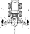
- Fig 1 Shows a top view of the stone picker 1, where for the understanding of the invention the most essential components are numbered.
- FIG 2 Shows a side view of the stone picker 1, where for the understanding of the invention the most essential components are numbered.
- Fig 3 Shows a rear view of the stone picker, where for the understanding of the invention the most essential components are numbered.
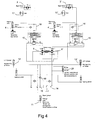
- Fig 4 shows the hydraulic scheme of the stone picker where for the understanding of the invention the most essential components are numbered.
- the rotors drive circuit An external hydraulic pressure connection 14 from the tractor, a cylinder 20, left and right hydraulic motor 6 and 6' for the lifting rotor 5, control valves 15 and 15' for left and right rake units 2 and 2' respectively, pilot operated check valves 16 and 16' for the left and right lift cylinders 4 and 4'of the left and right rake units, left and right non-return valves 17 and 17' with restricted bypass, the hydraulic motors 3 and 3' for the left and right rake units.
- Height adjustment circuit An external double acting connection 18 of the tractor, a pilot operated check valve 19, the left and right height adjustment cylinders 12 and 12', cylinder 20 and the pull cylinder 11 of the drawbar.
- the not shown mechanical transport security lock for the rake units 2 and 2' are opened.
- the tractor external hydraulic pressure connection 14 is activated and the lifting rotor 5 starts.
- the operating valves 15 and 15' for the rake units are activated in + position the rake units 2 and 2' are lowered since the return pressure from the hydraulic motors 3 and 3' of the rake units is big enough to open the check valves 16 and 16'.
- Both of the rake units 2 and 2' keeps now the same speed as they are driven by the return oil from the equally sized hydraulic motors 6 and 6' which are synchronized with each other through a shaft of the lifting rotor 5 and therefore distribute the oil from the tractor evenly to both of the rake units independent of their load.
- the required working depth is set by the tractor external hydraulic connection 18.
- the pivot operated check valve 19 prohibit during work the oil from leaking out of the height adjustment cylinders 12 and 12' back to the tractor.
- the pressure in the height adjustment cylinders 12 and 12' is equal high as the pressure on the piston rod side in the pull cylinder 11 of the drawbar.
- the working depth of the sieve head also determines how deep the lifting rotor 5 and also how deep towards the raking rotors directed parts of the rakes do work.
- the rotation resistance for all three rotors does increase, most of course for the lifting rotor 5 but also for the rotors of the rake units 2 and 2'.
- the pistonrod side of the cylinder 20 is connected to the pressure side of the hydraulic motors, while the piston side of the cylinder 20 is connected to the height adjustment cylinders 12.
- the cylinder 20 thus separate the oil in the rotation drive and in the height adjustment circuits from each other, but keeps the pressure relation between the pressure in these circuits on the level given by the area relation between the both chambers of the cylinder 20 gives.
- the area ratio between the piston- and piston rod sides of the cylinder 20 determinate, to what amount the of the rotation resistance depended parameters influence the depth control, in relation to how those parameters, which only are related to the pulling force in the drawbar.
- control cylinder 20 separate the oil in the hydraulic motors 6 and 6' and the height adjustment cylinders 12, 12' from each other, but the volume of chamber of the control cylinder 20 connected to the height adjustment cylinders 12 and 12' will also limit the working area of the load depending depth control.
- the automatic depth control will thereby be easy to oversteere by laying in or laying out oil manually from the height adjustment cylinder/cylinders.
- both of the hydraulic motors 6, 6' of the lifting rotor 5 do work also as flow dividers and do synchronize the speed between the rotors.
- the two hydraulic motors 6 and 6'do therefore give different torque on the shaft of the lifting rotor 5, in extreme case so that the left hydraulic motor instead of giving part of its effect to the lifting rotor instead is driven by this and then will act as a pump and can increase the working pressure of the hydraulic motor 3 of the left rake unit to the maximum pressure limit of the control valve 15, thus much higher than the system pressure of the tractor external hydraulic.
- connection of the hydraulic motors results in a power distribution between the hydraulic motors of the three rotors and supply the maximum power to that hydraulic motor that instantaneous has the highest external load.
- the hydraulically supplied power used, but also the kinetic energy stored especially in the heavy lifting rotor 5 with large diameter, but also the kinetic energy of the right hand raking rotor is used to help the hydraulic motor 3 of the left hand raking rotor over the load peak and vice versa.
- the pressure relief valve of the control valve 15 will open at 250 bar and oil is then free to bypass the motor 3 to tank. Even if a heavy heating occurs at this overload, an effective cooling of the overload protection is presented by the continuous oil flow through the valve. Thus, the relief pressure of the valve is kept on an even level without need of readjustment, cleaning operations or changing of parts as usually is the case by the traditional over load protections that up to now have been dominating on the stone pickers on the market.
- the raking rotor tends to stop because of tree roots or branches winding around it, or because of a suitably shaped stone that itch in between its throw fingers and the frame, it is only needed to reverse the control valve 15 of the hydraulic solution according the present innovation.
- the oil will then be directed to the lift cylinder 4 of the rake unit and release the unit from the ground. Simultaneously a part of the oil will flow through the restricted bypass of the one-way restrictor valve 17 to slowly reverse the raking rotor to release the blockage and the work can continue with a minimum of standstill and with maximum of safety for the driver.
- the hydraulic solution of the present innovation has many advantages compared to the state of the art hydraulic solutions in stone pickers.
- the work machine does of course not need to be a stone picker, but can be any work machine getting its hydraulic power supply from a base machine and who's own weight at least partly is unloaded by this.
- the number of driven rotors is neither limited to two, but can be any number.
- the area of use is neither limited to a within the agriculture used work machine, but can be for example a machine used within road or landscape construction and many variations thereof are possible within the scope of the patent claims below.
Description
- This innovation is related to a stone picker, especially hydraulic solutions to automatically optimize the load for a stone picker connected to a tractor or a base machine. Whereby at least part of the weight of the stone picker during work is transmitted to a tractor or base machine and where the stone picker comprises as well hydraulic motors as hydraulic cylinders.
- As the cultivated area per farm has heavily increased during the last decades and new areas have been cultivated, the need to collect stones from arable fields has strongly increased.
- A lot of different models of stone pickers have been presented in the patent literature as far as from early 1900 century, the oldest ones American or Canadian powered by horses, later powered by tractors and even selfpropelled models.
- From the simple (frequently British) tractor carried solutions presented in the patent literature in the late -50es and early -60es the Japanese started with their trailed solutions in the -70es. The US and Canada have also during this whole period a lot of patent applications. These were frequently intended to collect smaller stones in swaths, or different models of loading buckets to collect stones (from the swaths), or to take up single big stones, for example when new land was taken in cultivation.
- In the USSR a big number of patent applications and utility models have been presented from early -80es to the Soviet dissolution.
- As a forerunner to the solutions, also to those seen today as modern, can rightfully be considered the publication
FR2595185 - The throwing rotor of Tanguy is mounted in a separate frame, movable in relation to the sieve to enable also bigger stones to pass without blocking the rotor.
- Thus the publication
FR2595185 CS263662 - The publication
CS263662 - One can quickly convince oneself, that these in the mid 1980es presented solutions still are dominating the market by checking on the internet the offers of today-, and the producers of stone pickers.
- As an example we can from the home page of PEL-Tuote (http://pel-tuote.fi/sv/esitteet/) see how the Kivi-Pekka stone picker is build using the teachings from the French and the Czech solutions from 1986.
- As well it is possible to find a fairly similar solution on the Kongskilde home page (http://www.kongskilde.com/fi/fi-FI/Agriculture/Soil /Stone%20Collecting/Stone%20Collecting/JUKO%20STONEBEAR).
- Characteristically both the rotating stone rakes and the lifting rotor of a stone picker are mechanically driven from the tractor PT0 [power takeoff] by use of drive shafts, gearboxes and V-belts, showing as well benefits as disadvantages.
- The benefit with the mechanical transmission is that it is possible by use of quite simple and well-known components to transmit enough power and torque by normal load without disruption.
- The load on a stone picker is however all time strongly pulsating as a stone rake collects a flow of small and middle sized stones to the lifting rotor. The load shows additionally sharp load peaks as single big stones enter the machine. If the stones are oversized or unsuitable formed and enter the machine in "wrong edge", blockage will occur.
- Of course the mechanical transmission in known stone pickers is equipped with overload protections, but really these are mostly their Achilles' heel. Known types of overload protection used are multi disc friction clutches of standard type, or as in the above mentioned Kongskilde and PEL-Tuote machines V-belt transmissions between the gearbox and the rotors.
- The all-time pulsating load creates heating of the overload protections and as it is very difficult to equip these rotating components with an effective cooling. Therefor they easily are overheated and get unusable until their central components are replaced.
- The drive torque for V-belts used as overload protection is extremely sensitive to dirt and moisture on the belts. If they got wet or dirty they first have to be cleaned and dried, whereafter their pre-tension has to be checked and adjusted before the work can continue after an overload. That the cleaning and the adjusting of the V-belts really is difficult can clearly be understood thereby that for Kongskilde Kivikarhu, the instructions for adjusting and cleaning the V-belts go over three pages in the instruction manual and include advise to grind the grooves in the pulleys when the machine is standing and to clean and dry the belts before the interrupted work can continue.
- If the driver does not manage to disengage the PTO of the tractor immediately when overload occurs, these mechanical overload protections are very quickly overheated. The friction discs of the multidisc overload clutches get glazed and have to be replaced. The V- belts will burn and they also have to be replaced, adjusted and run in with due care during the run in period and thereafter readjusted checking the pre-tension rate during the run in time. (if doubt, see the instruction manual of Kivikarhu). All this additional work reduce the efficiency, gives expensive downtimes in the work and increase the risks concerning work safety.
- Therefore the Canadian producer Degelman for example, do produce stone pickers alternatively equipped with mechanical- or hydraulic transmissions. Check the presentation of their model Signature 7200 at: http://www.degelman.com/products/agricultural_equipment/rock_pickers_rakes/s ignature/index.php.
- The benefit of the mechanical transmission is that it can transmit high torques and the machine is therefore able to also collect big stones.
- The easy reverse possibility for the collecting rotor, offered by the hydraulic transmission is a big advantage during a blockage. Additionally the pressure relief valve of the hydraulic transmission gives a very reliable overload protection. The disadvantage is that the hydraulic capacity of most of the agricultural tractors normally available for this work is not with conventional solutions big enough to ensure the separate working units enough power to collect also big stones.
- To overcome these disadvantages with the known mechanical and hydraulic solutions for stone pickers, new hydraulic solutions according the present invention has been developed.
- The most important benefits with these new hydraulic solutions are, that effective and almost maintenance free overload protections are available for each separate work unit, and that the rotation speed of the separate driven units remain at required level also if the load between themselves vary.
- Furthermore a major advantage is that the load between the different driven units automatically is distributed to ensure that the heaviest loaded unit all time has access to spare power which the less loaded units does not momently use within the scope of the given maximal allowed drive power.
- This ensures, that the working pressure in the system, and the hydraulic power taken from the tractor or the base machine is held on the lowest possible level all the time, as the system pressure is not desired by the most loaded work unit but by the total load.
- Another big benefit is also that the cooling of the overload protections, in this case the pressure relief valves for the separate rotors is very effective as new oil all time flows through and cools them at possible stand stills for the single work unit, or at a total stop of the whole system.
- The overload limit is neither sensitive to external dirt nor does it need to be readjusted after an overload as for the above described traditional solutions.
- Furthermore it is easy to reverse the rotors at minor blockages. Downtime at work therefor almost disappears and the efficiency of the machine can all time be optimally used.
- Below an advantageous embodiment of the invention is described with use of the following drawings.
-
Fig 1 . Shows a top view of a stone picker, using the hydraulic solutions of the invention. -
Fig 2 . Shows the same machine in a side view. -
Fig 3 . Shows the same machine in a rear view. -
Fig 4 . Shows a typical hydraulic scheme for the hydraulic solutions according to the present invention. -
Fig 1 . Shows a top view of thestone picker 1, where for the understanding of the invention the most essential components are numbered. Left andright rake units 2 and 2',hydraulic motors 3 and 3' for left and right rake unit,lift cylinders 4 and 4' for left and right rake units, lift rotor 5, left and righthydraulic motors 6 and 6' for the lift rotor and support wheels for thestone rakes 9. -
Fig 2 . Shows a side view of thestone picker 1, where for the understanding of the invention the most essential components are numbered. Acarrier frame 7, with atandem unit 8, adrawbar 10, adrawbar pull cylinder 11, drawbarheight adjustment cylinders 12 and 12' and a sieve head 13'. -
Fig 3 . Shows a rear view of the stone picker, where for the understanding of the invention the most essential components are numbered. Asieve 13 under the lifting rotor 5. -
Fig 4 shows the hydraulic scheme of the stone picker where for the understanding of the invention the most essential components are numbered. - The rotors drive circuit: An external hydraulic pressure connection 14 from the tractor, a
cylinder 20, left and righthydraulic motor 6 and 6' for the lifting rotor 5,control valves 15 and 15' for left andright rake units 2 and 2' respectively, pilot operatedcheck valves 16 and 16' for the left andright lift cylinders 4 and 4'of the left and right rake units, left and rightnon-return valves 17 and 17' with restricted bypass, thehydraulic motors 3 and 3' for the left and right rake units. - Height adjustment circuit: An external
double acting connection 18 of the tractor, a pilot operatedcheck valve 19, the left and rightheight adjustment cylinders 12 and 12',cylinder 20 and thepull cylinder 11 of the drawbar. - Note, for the hydraulic connection to the tractor is only one double acting and one single acting connection + free return used. No from tractor electrically or cable operated hydraulic valves are needed.
- The function of the hydraulic solutions according the invention is as follow:
- The not shown mechanical transport security lock for the
rake units 2 and 2' are opened. The tractor external hydraulic pressure connection 14 is activated and the lifting rotor 5 starts. As the operatingvalves 15 and 15' for the rake units are activated in + position therake units 2 and 2' are lowered since the return pressure from thehydraulic motors 3 and 3' of the rake units is big enough to open thecheck valves 16 and 16'. - Both of the
rake units 2 and 2' keeps now the same speed as they are driven by the return oil from the equally sizedhydraulic motors 6 and 6' which are synchronized with each other through a shaft of the lifting rotor 5 and therefore distribute the oil from the tractor evenly to both of the rake units independent of their load. - The required working depth is set by the tractor external
hydraulic connection 18. The pivot operatedcheck valve 19 prohibit during work the oil from leaking out of theheight adjustment cylinders 12 and 12' back to the tractor. - When the machine is operating normally, the pressure in the
height adjustment cylinders 12 and 12' is equal high as the pressure on the piston rod side in thepull cylinder 11 of the drawbar. - If the machine tends to sink too deep, the pulling resistance will increase and the pressure in the
pull cylinder 11 of the drawbar will increase. Then oil is led from thiscylinder 11 to thehigh adjustment cylinders 12 and 12' and the working depth will decrease. - Here we have a kind of an automatic depth control based on the pulling force, it means depending on how deep the sieve head 13' penetrates into the soil and how hard the soil is.
- The working depth of the sieve head also determines how deep the lifting rotor 5 and also how deep towards the raking rotors directed parts of the rakes do work. At increased working depth and/or at heavier soil or by increased stone presence or by increased speed, the rotation resistance for all three rotors does increase, most of course for the lifting rotor 5 but also for the rotors of the
rake units 2 and 2'. - From the hydraulic scheme we can see that the pistonrod side of the
cylinder 20 is connected to the pressure side of the hydraulic motors, while the piston side of thecylinder 20 is connected to theheight adjustment cylinders 12. Thecylinder 20 thus separate the oil in the rotation drive and in the height adjustment circuits from each other, but keeps the pressure relation between the pressure in these circuits on the level given by the area relation between the both chambers of thecylinder 20 gives. - This means that the higher rotation resistance the rotors get, the more oil will be pressed out of the
cylinder 20 to theheight adjustment cylinders 12 and opposite, the lower the rotation resistance for the rotors is, the more oil is let out from theheight adjustment cylinders 12 to thecylinder 20 and the working depth of the machine will increase. - Therefore we get a load adapting depth regulation that not only take in account the pulling force, but the depth adjustment is regulated as a function of all the parameters: working depth, soil stiffness, stone presence, working speed and the rotation speed of the rotors. If the depth control is marked by Z, this adjustment can be written as a function:

- The area ratio between the piston- and piston rod sides of the
cylinder 20 determinate, to what amount the of the rotation resistance depended parameters influence the depth control, in relation to how those parameters, which only are related to the pulling force in the drawbar. - Thus it can often be a benefit to connect a second cylinder with another area ratio in parallel to the
cylinder 20 to get the possibility to during work adjust what influence (how heavily) the different parameters will have on the load depending depth control Z. - It should also be noted, that not only does the
control cylinder 20 separate the oil in thehydraulic motors 6 and 6' and theheight adjustment cylinders 12, 12' from each other, but the volume of chamber of thecontrol cylinder 20 connected to theheight adjustment cylinders 12 and 12' will also limit the working area of the load depending depth control. The automatic depth control will thereby be easy to oversteere by laying in or laying out oil manually from the height adjustment cylinder/cylinders. - When we look at the rotor drive we did already notice that both of the
hydraulic motors 6, 6' of the lifting rotor 5 do work also as flow dividers and do synchronize the speed between the rotors. - When we look at the dynamic pressure drop over the
hydraulic motors left rake unit 2 increase while the load on the right hand rake unit 2' remain constant. The pressure drop over thehydraulic motor 3 of the left hand rake unit increase. This results in a decreasing of the pressure drop over the lefthydraulic motor 6 of the lifting rotor 5. The twohydraulic motors 6 and 6'do therefore give different torque on the shaft of the lifting rotor 5, in extreme case so that the left hydraulic motor instead of giving part of its effect to the lifting rotor instead is driven by this and then will act as a pump and can increase the working pressure of thehydraulic motor 3 of the left rake unit to the maximum pressure limit of thecontrol valve 15, thus much higher than the system pressure of the tractor external hydraulic. - The connection of the hydraulic motors according to the present innovation, results in a power distribution between the hydraulic motors of the three rotors and supply the maximum power to that hydraulic motor that instantaneous has the highest external load. Here is not only the hydraulically supplied power used, but also the kinetic energy stored especially in the heavy lifting rotor 5 with large diameter, but also the kinetic energy of the right hand raking rotor is used to help the
hydraulic motor 3 of the left hand raking rotor over the load peak and vice versa. - If the load of the hydraulic motor of the left hand raking rotor all too big, the pressure relief valve of the
control valve 15 will open at 250 bar and oil is then free to bypass themotor 3 to tank. Even if a heavy heating occurs at this overload, an effective cooling of the overload protection is presented by the continuous oil flow through the valve. Thus, the relief pressure of the valve is kept on an even level without need of readjustment, cleaning operations or changing of parts as usually is the case by the traditional over load protections that up to now have been dominating on the stone pickers on the market. - If the raking rotor tends to stop because of tree roots or branches winding around it, or because of a suitably shaped stone that itch in between its throw fingers and the frame, it is only needed to reverse the
control valve 15 of the hydraulic solution according the present innovation. The oil will then be directed to thelift cylinder 4 of the rake unit and release the unit from the ground. Simultaneously a part of the oil will flow through the restricted bypass of the one-wayrestrictor valve 17 to slowly reverse the raking rotor to release the blockage and the work can continue with a minimum of standstill and with maximum of safety for the driver. - The fact that the load on the rotor first is automatically reduced by the oil supplied to the lift cylinder will of course help to reverse the rotor and release the blockage.
- As the above-described examples shows, the hydraulic solution of the present innovation has many advantages compared to the state of the art hydraulic solutions in stone pickers. The work machine does of course not need to be a stone picker, but can be any work machine getting its hydraulic power supply from a base machine and who's own weight at least partly is unloaded by this. The number of driven rotors is neither limited to two, but can be any number.
- The area of use is neither limited to a within the agriculture used work machine, but can be for example a machine used within road or landscape construction and many variations thereof are possible within the scope of the patent claims below.
-
- Ref
- Name / description
- 1
- Stone picker
- 2
- Left rake unit
- 2'
- Right rake unit
- 3
- Hydraulic motor of left rake unit
- 3'
- Hydraulic meter of right rake unit
- 4
- Lift cylinder of left rake unit
- 4'
- Lift cylinder of right rake unit
- 5
- Lifting rotor
- 6
- Left hydraulic motor of lifting rotor
- 6'
- Right hydraulic meter of lifting rotor
- 7
- Main frame
- 8
- Tandem unit
- 9
- Support wheels for the rake units
- 10
- Drawbar
- 11
- Pull cylinder of the drawbar
- 12
- Height adjustment cylinder left
- 12'
- Height adjustment cylinder right
- 13
- Sieve beneath the lifting rotor
- 13'
- Sieve head
- 14
- Tractor external hydraulic connection pressure
- 15
- Control valve of left rake unit
- 15'
- Control valve of right rake unit
- 16
- Pilot operated check valve of left lift cylinder
- 16'
- Pilot operated check valve of right lift cylinder
- 17
- Non-return valve with restricted bypass left
- 17'
- Non-return valve with restricted bypass right
- 18
- Tractor external double acting hydraulic connection
- 19
- Pilot operated check valve
- 20
- Cylinder
Claims (12)
- Stone picker (1) connected to an agricultural tractor or equivalent, the stone picker comprising
a lifting rotor (5),
at least one hydraulic motor (6, 6') arranged to drive said lifting rotor, a sieve (13) comprising a sieve head (13') arranged beneath the lifting rotor (5), and
left and right rake units (2, 2') comprising centre-oriented raking rotors,
hydraulic motors (3, 3') arranged to drive said rake units, and
at least three hydraulic cylinders (11, 12, 12', 20), characterized in that
the cylinder (11) is a drawbar pull cylinder mounted to sense the pulling resistance applied by the stone picker (1),
the cylinders (12, 12') are height adjustment cylinders, and
the cylinder (20) is a control cylinder, whereby
the drawbar pull cylinder (11), the height adjustment cylinders (12, 12') and the hydraulic motors (6, 6') driving the lifting rotor (5) are connected to the control cylinder (20) such, that
the drawbar pull cylinder and the height adjustment cylinders respectively the hydraulic motors are connected to an opposite chamber of the control cylinder, whereby
the control cylinder is arranged to keep the pressure relation between the pressure in opposite circuits comprising the drawbar pull cylinder (11) and the height adjustment cylinders (12, 12') on one hand and the hydraulic motors (6, 6') on the other hand, levelled, such a level being set by an area relation between the opposite chambers of the control cylinder (20). - A stone picker (1) according to claim 1, characterized in that a second cylinder (20) with another area ratio between chambers therein is connected in parallel to the first cylinder (20).
- A stone picker (1) according claim 1, characterized in that the height adjustment cylinders (12, 12') and the hydraulic motors (6, 6') are hydraulically separated from each other with two single acting with each other mechanically connected cylinders (20).
- A stone picker according to claim 1 or 2, characterized in that
at least one lift cylinder (4, 4') of the hydraulic driven rake units (2, 2') is connected to a return line of the hydraulic motor (3, 3') of the rake unit and that in a line connecting the lift cylinder and the hydraulic motor is arranged an one way restrictor valve (17, 17'),
said valve being set to increase the pressure in the return line when the motor is reversed, administrating an offloading of the rake unit (2, 2') from the ground when the motor (3, 3') thereof is reversed to free the rake unit from a blockage. - Method for hydraulically controlling a stone picker (1), which is connected to an agricultural tractor or equivalent, whereby the stone picker comprises
a lifting rotor (5),
at least one hydraulic motor (6, 6') driving said lifting rotor,
a sieve (13) comprising a sieve head (13') arranged beneath the lifting rotor (5), and
left and right rake units (2, 2') comprising centre-oriented raking rotors,
hydraulic motors (3, 3') driving said rake units, and
at least three hydraulic cylinders (11, 12, 12', 20), characterized in that
the hydraulic cylinders (12, 12') and the hydraulic motors (6, 6') of the lifting unit (5) are hydraulically separated from each other,
the hydraulic pressure of said hydraulic cylinders is compared with the hydraulic pressure of said hydraulic motors, hereby
adapting the length of the height adjustment cylinders (12, 12') as well to the pulling resistance of the stone picker (1) to the rotation resistance of its rotating work elements formed by the lifting rotor (5) and the rake units (2, 2'). - Method according to claim 5, characterized in that the the height adjustment cylinders (12, 12') and the hydraulic motors (6, 6') of the lifting unit (5) are hydraulically separated from each other by one or more double acting cylinders (20), hereby
connecting the hydraulic motors (6, 6'), and the height adjustment cylinders (12, 12') to opposite chambers of the control cylinder, whereby
the control cylinder (20) separates the oil of the height adjustment cylinders and the hydraulic motors from each other, while
the control cylinder (20) keeps the pressure relation between the respective pressures in the circuits formed by said cylinders and motors on a level corresponding to the area relation between the both chambers of the control cylinder (20). - Method according to claim 5, characterized in that the cylinders (12, 12') and the hydraulic motors (6, 6') of the lifting unit (5) are hydraulically separated from each other by two or more single acting hydraulic cylinders (20),
these cylinders being connected mechanically with each other in pairs, such that
the control cylinders (20) separate the oil of the height adjustment cylinders and the hydraulic motors from each other, while
the control cylinders (20) keep the pressure relation between the respective pressures in the circuits formed by said cylinders and motors on a level corresponding to the area relation between the both chambers of the control cylinders (20). - Method according to claim 6 or 7, characterized in that the area ratio, of the cylinder (20), decide how the ratio between the on one hand a registered rotation resistance of the lifting rotor (5) and the left and right rake units (2, 2') and on another hand a registered pulling resistance of the sieve (13) and the sieve head (13') thereof affects the length of the length of the drawbar pull cylinder (11), or height adjustment cylinders (12, 12').
- Method according to claim 6, 7 or 8, characterized in that the hydraulic volume of the cylinder (20) limits the motion range of the load depending depth control.
- Method according to any of the claims 5 to 9, characterized in that the oil supply to the cylinders (4, 4', 12, 12') controlling the depth control is manually regulated.
- Method according to any of the claims 5 to 10, characterized in that
at least one lift cylinder (4, 4') of the hydraulically driven rake units (2, 2') is connected to the return line of the hydraulic motor (3, 3') of the rake unit, and
a one way restrictor valve (17, 17') is installed in a hydraulic line between the lift cylinder and the hydraulic motor to increase the pressure in the return line when the motor (3, 3') is reversed, so that the rake unit (2, 2') automatically is offloaded from the ground when the motor (3, 3') thereof is reversed, thus
setting the rotor free from a blockage and to simultaneous reducing the reverse speed of the rotor. - Method according to any of the claims 5 to 11, characterized in that the pulling resistance of the sieve head (13') is registered by one or more hydraulic cylinders (11) co-operating with the connection between the stone picker (1) and the agricultural tractor or equivalent.
Priority Applications (1)
| Application Number | Priority Date | Filing Date | Title |
|---|---|---|---|
| PL16823936T PL3322276T3 (en) | 2015-07-10 | 2016-07-05 | Hydraulic solutions on a work machine |
Applications Claiming Priority (2)
| Application Number | Priority Date | Filing Date | Title |
|---|---|---|---|
| FI20150213A FI127517B (en) | 2015-07-10 | 2015-07-10 | Hydraulic solutions for a work vehicle |
| PCT/FI2016/000018 WO2017009521A1 (en) | 2015-07-10 | 2016-07-05 | Hydraulic solutions on a work machine |
Publications (3)
| Publication Number | Publication Date |
|---|---|
| EP3322276A1 EP3322276A1 (en) | 2018-05-23 |
| EP3322276A4 EP3322276A4 (en) | 2019-04-17 |
| EP3322276B1 true EP3322276B1 (en) | 2021-06-02 |
Family
ID=57756872
Family Applications (2)
| Application Number | Title | Priority Date | Filing Date |
|---|---|---|---|
| EP16823935.8A Active EP3319410B1 (en) | 2015-07-10 | 2016-07-05 | Hydraulic solutions on a work machine |
| EP16823936.6A Active EP3322276B1 (en) | 2015-07-10 | 2016-07-05 | Hydraulic solutions on a work machine |
Family Applications Before (1)
| Application Number | Title | Priority Date | Filing Date |
|---|---|---|---|
| EP16823935.8A Active EP3319410B1 (en) | 2015-07-10 | 2016-07-05 | Hydraulic solutions on a work machine |
Country Status (7)
| Country | Link |
|---|---|
| US (1) | US10674653B2 (en) |
| EP (2) | EP3319410B1 (en) |
| CA (2) | CA2990531C (en) |
| ES (1) | ES2784887T3 (en) |
| FI (1) | FI127517B (en) |
| PL (2) | PL3322276T3 (en) |
| WO (2) | WO2017009521A1 (en) |
Families Citing this family (7)
| Publication number | Priority date | Publication date | Assignee | Title |
|---|---|---|---|---|
| EP3571200B8 (en) | 2017-01-17 | 2022-08-03 | HepaRegeniX GmbH | Protein kinase inhibitors for promoting liver regeneration or reducing or preventing hepatocyte death |
| CN107580809A (en) * | 2017-10-21 | 2018-01-16 | 安徽特种农业装备产业技术研究院有限公司 | A kind of stone collector picks up stone roll structure |
| CN108952646B (en) * | 2018-09-11 | 2019-09-27 | 大庆丹枫石油技术开发有限公司 | Smart well fluid controller |
| CN109441900A (en) * | 2018-12-10 | 2019-03-08 | 扬州盛达特种车有限公司 | A kind of energy-saving hydraulic system of pavement cleaning vehicle |
| CN111052900B (en) * | 2019-12-23 | 2022-02-25 | 济南工程职业技术学院 | Building land restoration device |
| CN112262629B (en) * | 2020-11-18 | 2023-02-28 | 艾海提·阿卜力米提 | Straw returning and residual film recycling machine matched with four-wheel tractor |
| DE102021114309A1 (en) | 2021-06-02 | 2022-12-08 | Markus Lembeck | Separating device for collecting machine and method |
Family Cites Families (16)
| Publication number | Priority date | Publication date | Assignee | Title |
|---|---|---|---|---|
| US3540534A (en) | 1969-04-01 | 1970-11-17 | Basil C Rhoads | Stone gathering machine |
| US3627053A (en) | 1969-04-28 | 1971-12-14 | Deere & Co | Hydraulic power lift system for tractor and trailing implement |
| US3670822A (en) | 1970-07-02 | 1972-06-20 | Clark Equipment Co | Implement load transfer |
| US4637474A (en) * | 1974-11-05 | 1987-01-20 | Leonard Willie B | Tractor and towed implement with elevation control system for implement including pressure responsive valve actuator |
| CA984615A (en) | 1975-06-04 | 1976-03-02 | Leslie Hulicsko | Rock picker |
| FR2595185B1 (en) | 1986-03-07 | 1989-06-30 | Tanguy Maurice | IMPROVEMENTS IN MACHINES FOR REMOVING STONES FROM THE GROUND |
| CS263662B1 (en) | 1986-12-05 | 1989-04-14 | Miroslav Ing Svoboda | Stone collector |
| US5430999A (en) | 1994-09-01 | 1995-07-11 | Grant; Spencer A. | Tree trimming and pruning machine |
| US5511368A (en) * | 1995-01-20 | 1996-04-30 | Kocher; Norman E. | Rough terrain hydraulic mower attachment |
| JP3490027B2 (en) | 1999-07-08 | 2004-01-26 | 株式会社クボタ | Work vehicle |
| US6922992B1 (en) * | 2002-09-24 | 2005-08-02 | George H. Morgan | Hydraulic drive circuit with flow divider and bypass valve |
| US7658233B1 (en) * | 2008-09-03 | 2010-02-09 | Aho Melvin S | Self-propelled transportable rock picker |
| WO2011078846A1 (en) | 2009-12-21 | 2011-06-30 | Aho Melvin S | Improved self-propelled transportable rock picker |
| US8408149B2 (en) | 2011-05-20 | 2013-04-02 | Deere & Company | Ground working machine with a blockage clearing system and method of operation |
| WO2015019942A1 (en) | 2013-08-09 | 2015-02-12 | ヤンマー株式会社 | Work-apparatus orientation control device |
| US20160029539A1 (en) | 2013-10-18 | 2016-02-04 | Mark Aho | Detachable Transportable Rock Picker |
-
2015
- 2015-07-10 FI FI20150213A patent/FI127517B/en active IP Right Grant
-
2016
- 2016-07-05 CA CA2990531A patent/CA2990531C/en active Active
- 2016-07-05 PL PL16823936T patent/PL3322276T3/en unknown
- 2016-07-05 EP EP16823935.8A patent/EP3319410B1/en active Active
- 2016-07-05 CA CA2990522A patent/CA2990522C/en active Active
- 2016-07-05 EP EP16823936.6A patent/EP3322276B1/en active Active
- 2016-07-05 PL PL16823935T patent/PL3319410T3/en unknown
- 2016-07-05 ES ES16823935T patent/ES2784887T3/en active Active
- 2016-07-05 WO PCT/FI2016/000018 patent/WO2017009521A1/en active Application Filing
- 2016-07-05 US US15/742,235 patent/US10674653B2/en active Active
- 2016-07-05 WO PCT/FI2016/000017 patent/WO2017009520A1/en active Application Filing
Also Published As
| Publication number | Publication date |
|---|---|
| EP3319410B1 (en) | 2020-02-19 |
| US10674653B2 (en) | 2020-06-09 |
| US20180192574A1 (en) | 2018-07-12 |
| CA2990522C (en) | 2020-09-22 |
| PL3322276T3 (en) | 2021-12-27 |
| EP3319410A1 (en) | 2018-05-16 |
| CA2990522A1 (en) | 2017-01-19 |
| PL3319410T3 (en) | 2020-07-13 |
| EP3322276A1 (en) | 2018-05-23 |
| FI127517B (en) | 2018-08-15 |
| EP3319410A4 (en) | 2019-03-13 |
| WO2017009521A1 (en) | 2017-01-19 |
| FI20150213A (en) | 2017-01-11 |
| CA2990531A1 (en) | 2017-01-19 |
| WO2017009520A1 (en) | 2017-01-19 |
| EP3322276A4 (en) | 2019-04-17 |
| CA2990531C (en) | 2021-11-02 |
| ES2784887T3 (en) | 2020-10-01 |
Similar Documents
| Publication | Publication Date | Title |
|---|---|---|
| EP3322276B1 (en) | Hydraulic solutions on a work machine | |
| CN103875360B (en) | High-clearance rice harvester | |
| AU678252B2 (en) | Harvester with hydraulically driven, flow-compensated rotary cutter bed | |
| EP1570724B1 (en) | Driving assembly to drive a harvester head of a harvester | |
| EP1862057A1 (en) | Attachment device for harvesting stalk crops | |
| AU7311794A (en) | Wide cut harvester having rotary cutter bed | |
| CN107996129A (en) | A kind of efficient grass-remover | |
| US4129258A (en) | Automatic hydraulic series-parallel shift device for implement | |
| JP4529920B2 (en) | Combine | |
| CN205961849U (en) | Multi -functional stem stalk root stubble picks up machine | |
| CN115119555B (en) | Hydraulic drive type full-automatic transplanting combined machine | |
| EP2686560B1 (en) | Auxiliary drive for working implements | |
| CN208387303U (en) | A kind of multi-functional shrub cropper | |
| FI128071B (en) | Hydraulic solutions for a work vehicle | |
| JP4529898B2 (en) | Combine | |
| EP1183933A1 (en) | Turf-care apparatus with hydraulic power transmission | |
| CN206078104U (en) | Grass harvesting machine | |
| EP2702860B1 (en) | Self-propelled agricultural harvester | |
| CN201127185Y (en) | Rear-mounted mowing machine transmitted by tractor rear output shaft | |
| CN203860057U (en) | Large-ground-clearance rice harvester | |
| CN206100832U (en) | High case soil preparation of through shaft type machine | |
| CN206181804U (en) | Peanut harvester | |
| CN206433390U (en) | Folding utility corn harvester header | |
| Krukow | Hydraulic Systems for Grain Harvesting | |
| Boast | FOR TRACTORS |
Legal Events
| Date | Code | Title | Description |
|---|---|---|---|
| STAA | Information on the status of an ep patent application or granted ep patent |
Free format text: STATUS: THE INTERNATIONAL PUBLICATION HAS BEEN MADE |
|
| PUAI | Public reference made under article 153(3) epc to a published international application that has entered the european phase |
Free format text: ORIGINAL CODE: 0009012 |
|
| STAA | Information on the status of an ep patent application or granted ep patent |
Free format text: STATUS: REQUEST FOR EXAMINATION WAS MADE |
|
| 17P | Request for examination filed |
Effective date: 20180207 |
|
| AK | Designated contracting states |
Kind code of ref document: A1 Designated state(s): AL AT BE BG CH CY CZ DE DK EE ES FI FR GB GR HR HU IE IS IT LI LT LU LV MC MK MT NL NO PL PT RO RS SE SI SK SM TR |
|
| AX | Request for extension of the european patent |
Extension state: BA ME |
|
| DAV | Request for validation of the european patent (deleted) | ||
| DAX | Request for extension of the european patent (deleted) | ||
| A4 | Supplementary search report drawn up and despatched |
Effective date: 20190315 |
|
| RIC1 | Information provided on ipc code assigned before grant |
Ipc: A01B 63/111 20060101ALI20190311BHEP Ipc: F15B 3/00 20060101ALI20190311BHEP Ipc: A01B 43/00 20060101AFI20190311BHEP |
|
| GRAP | Despatch of communication of intention to grant a patent |
Free format text: ORIGINAL CODE: EPIDOSNIGR1 |
|
| STAA | Information on the status of an ep patent application or granted ep patent |
Free format text: STATUS: GRANT OF PATENT IS INTENDED |
|
| INTG | Intention to grant announced |
Effective date: 20201216 |
|
| GRAS | Grant fee paid |
Free format text: ORIGINAL CODE: EPIDOSNIGR3 |
|
| GRAA | (expected) grant |
Free format text: ORIGINAL CODE: 0009210 |
|
| STAA | Information on the status of an ep patent application or granted ep patent |
Free format text: STATUS: THE PATENT HAS BEEN GRANTED |
|
| REG | Reference to a national code |
Ref country code: CH Ref legal event code: EP |
|
| AK | Designated contracting states |
Kind code of ref document: B1 Designated state(s): AL AT BE BG CH CY CZ DE DK EE ES FI FR GB GR HR HU IE IS IT LI LT LU LV MC MK MT NL NO PL PT RO RS SE SI SK SM TR |
|
| REG | Reference to a national code |
Ref country code: GB Ref legal event code: FG4D |
|
| REG | Reference to a national code |
Ref country code: AT Ref legal event code: REF Ref document number: 1397574 Country of ref document: AT Kind code of ref document: T Effective date: 20210615 |
|
| REG | Reference to a national code |
Ref country code: IE Ref legal event code: FG4D |
|
| REG | Reference to a national code |
Ref country code: DE Ref legal event code: R096 Ref document number: 602016058917 Country of ref document: DE |
|
| REG | Reference to a national code |
Ref country code: SE Ref legal event code: TRGR |
|
| REG | Reference to a national code |
Ref country code: LT Ref legal event code: MG9D |
|
| REG | Reference to a national code |
Ref country code: NO Ref legal event code: T2 Effective date: 20210602 |
|
| PG25 | Lapsed in a contracting state [announced via postgrant information from national office to epo] |
Ref country code: FI Free format text: LAPSE BECAUSE OF FAILURE TO SUBMIT A TRANSLATION OF THE DESCRIPTION OR TO PAY THE FEE WITHIN THE PRESCRIBED TIME-LIMIT Effective date: 20210602 Ref country code: LT Free format text: LAPSE BECAUSE OF FAILURE TO SUBMIT A TRANSLATION OF THE DESCRIPTION OR TO PAY THE FEE WITHIN THE PRESCRIBED TIME-LIMIT Effective date: 20210602 Ref country code: HR Free format text: LAPSE BECAUSE OF FAILURE TO SUBMIT A TRANSLATION OF THE DESCRIPTION OR TO PAY THE FEE WITHIN THE PRESCRIBED TIME-LIMIT Effective date: 20210602 Ref country code: BG Free format text: LAPSE BECAUSE OF FAILURE TO SUBMIT A TRANSLATION OF THE DESCRIPTION OR TO PAY THE FEE WITHIN THE PRESCRIBED TIME-LIMIT Effective date: 20210902 |
|
| REG | Reference to a national code |
Ref country code: NL Ref legal event code: MP Effective date: 20210602 |
|
| REG | Reference to a national code |
Ref country code: AT Ref legal event code: MK05 Ref document number: 1397574 Country of ref document: AT Kind code of ref document: T Effective date: 20210602 |
|
| PG25 | Lapsed in a contracting state [announced via postgrant information from national office to epo] |
Ref country code: LV Free format text: LAPSE BECAUSE OF FAILURE TO SUBMIT A TRANSLATION OF THE DESCRIPTION OR TO PAY THE FEE WITHIN THE PRESCRIBED TIME-LIMIT Effective date: 20210602 Ref country code: GR Free format text: LAPSE BECAUSE OF FAILURE TO SUBMIT A TRANSLATION OF THE DESCRIPTION OR TO PAY THE FEE WITHIN THE PRESCRIBED TIME-LIMIT Effective date: 20210903 Ref country code: RS Free format text: LAPSE BECAUSE OF FAILURE TO SUBMIT A TRANSLATION OF THE DESCRIPTION OR TO PAY THE FEE WITHIN THE PRESCRIBED TIME-LIMIT Effective date: 20210602 |
|
| PG25 | Lapsed in a contracting state [announced via postgrant information from national office to epo] |
Ref country code: ES Free format text: LAPSE BECAUSE OF FAILURE TO SUBMIT A TRANSLATION OF THE DESCRIPTION OR TO PAY THE FEE WITHIN THE PRESCRIBED TIME-LIMIT Effective date: 20210602 Ref country code: RO Free format text: LAPSE BECAUSE OF FAILURE TO SUBMIT A TRANSLATION OF THE DESCRIPTION OR TO PAY THE FEE WITHIN THE PRESCRIBED TIME-LIMIT Effective date: 20210602 Ref country code: PT Free format text: LAPSE BECAUSE OF FAILURE TO SUBMIT A TRANSLATION OF THE DESCRIPTION OR TO PAY THE FEE WITHIN THE PRESCRIBED TIME-LIMIT Effective date: 20211004 Ref country code: NL Free format text: LAPSE BECAUSE OF FAILURE TO SUBMIT A TRANSLATION OF THE DESCRIPTION OR TO PAY THE FEE WITHIN THE PRESCRIBED TIME-LIMIT Effective date: 20210602 Ref country code: EE Free format text: LAPSE BECAUSE OF FAILURE TO SUBMIT A TRANSLATION OF THE DESCRIPTION OR TO PAY THE FEE WITHIN THE PRESCRIBED TIME-LIMIT Effective date: 20210602 Ref country code: AT Free format text: LAPSE BECAUSE OF FAILURE TO SUBMIT A TRANSLATION OF THE DESCRIPTION OR TO PAY THE FEE WITHIN THE PRESCRIBED TIME-LIMIT Effective date: 20210602 Ref country code: SM Free format text: LAPSE BECAUSE OF FAILURE TO SUBMIT A TRANSLATION OF THE DESCRIPTION OR TO PAY THE FEE WITHIN THE PRESCRIBED TIME-LIMIT Effective date: 20210602 Ref country code: SK Free format text: LAPSE BECAUSE OF FAILURE TO SUBMIT A TRANSLATION OF THE DESCRIPTION OR TO PAY THE FEE WITHIN THE PRESCRIBED TIME-LIMIT Effective date: 20210602 |
|
| REG | Reference to a national code |
Ref country code: CH Ref legal event code: PL |
|
| REG | Reference to a national code |
Ref country code: DE Ref legal event code: R097 Ref document number: 602016058917 Country of ref document: DE |
|
| PG25 | Lapsed in a contracting state [announced via postgrant information from national office to epo] |
Ref country code: MC Free format text: LAPSE BECAUSE OF FAILURE TO SUBMIT A TRANSLATION OF THE DESCRIPTION OR TO PAY THE FEE WITHIN THE PRESCRIBED TIME-LIMIT Effective date: 20210602 |
|
| REG | Reference to a national code |
Ref country code: BE Ref legal event code: MM Effective date: 20210731 |
|
| PLBE | No opposition filed within time limit |
Free format text: ORIGINAL CODE: 0009261 |
|
| STAA | Information on the status of an ep patent application or granted ep patent |
Free format text: STATUS: NO OPPOSITION FILED WITHIN TIME LIMIT |
|
| PG25 | Lapsed in a contracting state [announced via postgrant information from national office to epo] |
Ref country code: LI Free format text: LAPSE BECAUSE OF NON-PAYMENT OF DUE FEES Effective date: 20210731 Ref country code: DK Free format text: LAPSE BECAUSE OF FAILURE TO SUBMIT A TRANSLATION OF THE DESCRIPTION OR TO PAY THE FEE WITHIN THE PRESCRIBED TIME-LIMIT Effective date: 20210602 Ref country code: CH Free format text: LAPSE BECAUSE OF NON-PAYMENT OF DUE FEES Effective date: 20210731 |
|
| 26N | No opposition filed |
Effective date: 20220303 |
|
| GBPC | Gb: european patent ceased through non-payment of renewal fee |
Effective date: 20210902 |
|
| PG25 | Lapsed in a contracting state [announced via postgrant information from national office to epo] |
Ref country code: LU Free format text: LAPSE BECAUSE OF NON-PAYMENT OF DUE FEES Effective date: 20210705 Ref country code: AL Free format text: LAPSE BECAUSE OF FAILURE TO SUBMIT A TRANSLATION OF THE DESCRIPTION OR TO PAY THE FEE WITHIN THE PRESCRIBED TIME-LIMIT Effective date: 20210602 |
|
| PG25 | Lapsed in a contracting state [announced via postgrant information from national office to epo] |
Ref country code: IT Free format text: LAPSE BECAUSE OF FAILURE TO SUBMIT A TRANSLATION OF THE DESCRIPTION OR TO PAY THE FEE WITHIN THE PRESCRIBED TIME-LIMIT Effective date: 20210602 Ref country code: IE Free format text: LAPSE BECAUSE OF NON-PAYMENT OF DUE FEES Effective date: 20210705 Ref country code: GB Free format text: LAPSE BECAUSE OF NON-PAYMENT OF DUE FEES Effective date: 20210902 Ref country code: BE Free format text: LAPSE BECAUSE OF NON-PAYMENT OF DUE FEES Effective date: 20210731 |
|
| PG25 | Lapsed in a contracting state [announced via postgrant information from national office to epo] |
Ref country code: HU Free format text: LAPSE BECAUSE OF FAILURE TO SUBMIT A TRANSLATION OF THE DESCRIPTION OR TO PAY THE FEE WITHIN THE PRESCRIBED TIME-LIMIT; INVALID AB INITIO Effective date: 20160705 |
|
| PG25 | Lapsed in a contracting state [announced via postgrant information from national office to epo] |
Ref country code: CY Free format text: LAPSE BECAUSE OF FAILURE TO SUBMIT A TRANSLATION OF THE DESCRIPTION OR TO PAY THE FEE WITHIN THE PRESCRIBED TIME-LIMIT Effective date: 20210602 |
|
| PGFP | Annual fee paid to national office [announced via postgrant information from national office to epo] |
Ref country code: CZ Payment date: 20230607 Year of fee payment: 8 |
|
| PGFP | Annual fee paid to national office [announced via postgrant information from national office to epo] |
Ref country code: PL Payment date: 20230626 Year of fee payment: 8 |
|
| PGFP | Annual fee paid to national office [announced via postgrant information from national office to epo] |
Ref country code: NO Payment date: 20230717 Year of fee payment: 8 |
|
| PGFP | Annual fee paid to national office [announced via postgrant information from national office to epo] |
Ref country code: SE Payment date: 20230720 Year of fee payment: 8 Ref country code: FR Payment date: 20230724 Year of fee payment: 8 Ref country code: DE Payment date: 20230719 Year of fee payment: 8 |