EP3321647B1 - Wägesystem - Google Patents
Wägesystem Download PDFInfo
- Publication number
- EP3321647B1 EP3321647B1 EP16197901.8A EP16197901A EP3321647B1 EP 3321647 B1 EP3321647 B1 EP 3321647B1 EP 16197901 A EP16197901 A EP 16197901A EP 3321647 B1 EP3321647 B1 EP 3321647B1
- Authority
- EP
- European Patent Office
- Prior art keywords
- weighing
- hook
- sausages
- suspension
- sausage
- Prior art date
- Legal status (The legal status is an assumption and is not a legal conclusion. Google has not performed a legal analysis and makes no representation as to the accuracy of the status listed.)
- Active
Links
Images


Classifications
-
- G—PHYSICS
- G01—MEASURING; TESTING
- G01G—WEIGHING
- G01G19/00—Weighing apparatus or methods adapted for special purposes not provided for in the preceding groups
-
- A—HUMAN NECESSITIES
- A22—BUTCHERING; MEAT TREATMENT; PROCESSING POULTRY OR FISH
- A22C—PROCESSING MEAT, POULTRY, OR FISH
- A22C11/00—Sausage making ; Apparatus for handling or conveying sausage products during manufacture
- A22C11/02—Sausage filling or stuffing machines
- A22C11/0245—Controlling devices
- A22C11/0254—Sizing means
-
- A—HUMAN NECESSITIES
- A22—BUTCHERING; MEAT TREATMENT; PROCESSING POULTRY OR FISH
- A22C—PROCESSING MEAT, POULTRY, OR FISH
- A22C11/00—Sausage making ; Apparatus for handling or conveying sausage products during manufacture
- A22C11/02—Sausage filling or stuffing machines
- A22C11/0245—Controlling devices
-
- A—HUMAN NECESSITIES
- A22—BUTCHERING; MEAT TREATMENT; PROCESSING POULTRY OR FISH
- A22C—PROCESSING MEAT, POULTRY, OR FISH
- A22C15/00—Apparatus for hanging-up meat or sausages
- A22C15/001—Specially adapted for hanging or conveying several sausages or strips of meat
-
- G—PHYSICS
- G01—MEASURING; TESTING
- G01G—WEIGHING
- G01G11/00—Apparatus for weighing a continuous stream of material during flow; Conveyor belt weighers
- G01G11/08—Apparatus for weighing a continuous stream of material during flow; Conveyor belt weighers having means for controlling the rate of feed or discharge
-
- G—PHYSICS
- G01—MEASURING; TESTING
- G01G—WEIGHING
- G01G13/00—Weighing apparatus with automatic feed or discharge for weighing-out batches of material
- G01G13/24—Weighing mechanism control arrangements for automatic feed or discharge
- G01G13/28—Weighing mechanism control arrangements for automatic feed or discharge involving variation of an electrical variable which is used to control loading or discharge of the receptacle
-
- G—PHYSICS
- G01—MEASURING; TESTING
- G01G—WEIGHING
- G01G19/00—Weighing apparatus or methods adapted for special purposes not provided for in the preceding groups
- G01G19/02—Weighing apparatus or methods adapted for special purposes not provided for in the preceding groups for weighing wheeled or rolling bodies, e.g. vehicles
- G01G19/04—Weighing apparatus or methods adapted for special purposes not provided for in the preceding groups for weighing wheeled or rolling bodies, e.g. vehicles for weighing railway vehicles
- G01G19/06—Weighing apparatus or methods adapted for special purposes not provided for in the preceding groups for weighing wheeled or rolling bodies, e.g. vehicles for weighing railway vehicles on overhead rails
-
- G—PHYSICS
- G01—MEASURING; TESTING
- G01G—WEIGHING
- G01G19/00—Weighing apparatus or methods adapted for special purposes not provided for in the preceding groups
- G01G19/14—Weighing apparatus or methods adapted for special purposes not provided for in the preceding groups for weighing suspended loads
-
- G—PHYSICS
- G01—MEASURING; TESTING
- G01G—WEIGHING
- G01G21/00—Details of weighing apparatus
- G01G21/22—Weigh pans or other weighing receptacles; Weighing platforms
Definitions
- the invention relates to a suspension device, a filling machine and an operating method for producing sausages according to the preambles of claims 1, 8 and 9.
- a suspension device is already from EP 2 305 043 A1 known, which already shows hanging hooks, over which the weight of a sausage can be determined.
- WO 2015/15663 A1 already describes a suspension device with hooks that can be used, for example, to weigh chickens.
- sausage casings for example natural, artificial or collagen casings
- a filling machine in particular a vacuum filling machine.
- a sausage chain consisting of connected individual sausages or portions results in the twisting line.
- hooks grasp the specified compartment locations so that several sausage loops form on the sausage chain on the suspension unit (see e.g. Figure 10a ).
- Such a loop consists of several sausages (3-loop, 4-loop, in Figure 10a 6 loop).
- portion weights that are as accurate as possible, i.e. the sausage weights that are as constant as possible
- the sausages are weighed before or during product removal at certain time intervals or after a defined production quantity with the help of a separate weighing system.
- Individual or connected sausages or smoking sticks completely hung with sausage loops can be weighed.
- stand-alone weighing systems can be used here as smoke stick / portion scales.
- the space available in the production hall is limited.
- a stand-alone weighing system requires additional space in addition to the actual filling and portioning system. The machine operator must remove the products and walk to the weighing system. This means a disruption of the actual workflow for the operator and longer production interruptions / stops can occur.
- the sausages hung in sausage loops on the smoking stick can slip on the smoking stick due to the transport to the scales, so that a uniform distance between the sausages is not guaranteed, which is, for example, disadvantageous in subsequent treatment steps such as smoking, etc., since the products are in this case not allowed to touch.
- the present invention is based on the object of improving the portion accuracy of the sausages produced in a simple manner, while at the same time disrupting the production process as little as possible.
- the weighing device is integrated in the suspension device. This eliminates the need to transport the sausages from the suspension device to the weighing device, which can prevent or at least significantly reduce production interruptions and stops. In this way, the filling process and the production process can be optimized. Because the weighing device is integrated in the suspension device, no additional space is required in the production hall for the weighing device. Because the weighing device is integrated in the suspension device, additional installation work and installation costs are omitted. Overall, the weighing device can be implemented more cost-effectively. The weighing device can thus advantageously be moved together with the suspension device in the production room and is not restricted to a specific space. This brings with it an extraordinary flexibility, since the position of the individual machines can be freely selected and changed. Thanks to the integrated load cell, the workflow becomes the operator of the Suspension device less disturbed because the weighing process can be carried out directly on the suspension device.
- the present invention allows not only a manual weighing process, but also a semi-automatic or automatic weighing process in which at least one receiving hook is connected to a load cell such that the weight of the at least one sausage or sausage chain can be determined on the receiving hook.
- the hook can be connected to the load cell via a device that holds the hook and bears its weight. This device for holding the weight preferably also has a guiding function for the hook.
- the weight of the at least one sausage on at least one hook can thus be determined, i.e. the weight of a desired number of sausages without them having to be removed from the hook.
- the suspension device has a hook guide on which the receiving hooks can revolve on their orbit.
- the hook guide has the function of guiding the hooks on their path and at the same time carrying the weight of the hooks.
- the hook guide can be connected to a load cell at least in sections. If, for example, the entire hook guide is connected to one or more load cells, the weight of all sausages that are on the suspension device at a specific measurement time can be determined. But it is also possible that the weight is only determined in one or more weighing sections of the hook guide.
- the weighing device comprises a guide part integrated in a weighing section of the hook guide and decoupled from the hook guide, on which the suspension hooks can be guided and held in the weighing section, this guide part being connected to the weighing cell.
- the guide part used takes over the functions of Hook guide in the weighing section. Because the guide part in the weighing section is decoupled from the hook guide, only the weight of the sausage or sausages that are arranged on the hooks in this weighing section is determined.
- a corresponding arrangement is particularly cost-effective, space-saving and easy to implement.
- the transport of the suspension hooks can be stopped for a certain measuring period and the weight of the sausages on the hooks, which are arranged in the weighing section, can be determined.
- a corresponding arrangement enables a semi-automatic weighing system in which the operator initiates the weighing process himself, but also an automatic weighing system in which a controller initiates and ends the weighing process.
- the circumferential hook guide has at least one recess into which a guide section of the guide part is inserted, the guide section being connected to the weighing cell via a connecting section.
- a hook guide is used that guides the upper hook area at two vertically one above the other, it is advantageous if an upper and a lower recess are provided in the weighing section in the hook guide, in which respective guide sections are used, which then function take over the actual hook guide.
- the respective guide sections decoupled from the rest of the guide can then be connected to one another via a connecting section, the connecting section being connected to the weighing cell.
- the hook guide is completely removed in the weighing section and the decoupled guide part is used here in order to take over the functions of the hook guide.
- the suspension device has a circumferential drive element, for example a drive belt, which engages with the suspension hooks.
- the receiving hooks to be weighed are decoupled from the drive element.
- the guide part for uncoupling can be moved in a direction transverse to the transport direction of the sausages, in such a way that the hook moves away from the drive element. This eliminates the influence of the drive element on the weighing process. This enables the individual sausages to be weighed even more precisely. After the weighing process, for example, the guide part moves back again so that the suspension hooks are connected to the drive element again.
- the weighing section has a length such that the weight of at least one sausage can be detected on at least one hanging hook.
- the weighing section can also have a length so that it can weigh several hanging hooks hung with sausages.
- 1 to 50 suspension hooks can be weighed in the weighing section, the weighing section having a length of 20 mm to 1500 mm, for example.
- the weight of an entire group of sausages that is removed from a smoking stick can be determined.
- the suspension device comprises a display and operating unit, namely a display unit which is provided in addition to the display and operating unit of the filling machine and is designed, for example, as a touchscreen.
- This display and operating unit preferably has an input device for starting the weighing process and / or an input device for inputting a number of sausages of the sausages to be weighed or for confirming that the number of sausages to be weighed is correct.
- the display and operating unit can also indicate to the operator that a weighing process must be carried out or specify a weighing period.
- the additionally provided display and control unit has the advantage that it is always guaranteed, especially in the manual and semi-automatic system, that the weighed weight relates to the correct number of sausages. In this way, the error rate can be significantly reduced. This ensures that there is no incorrect regulation of the filling process. The filling process can then be regulated by evaluating the weight data.
- the invention also relates to a filling machine with the suspension device according to the invention according to at least one of claims 1-7.
- the weighing device of the suspension device can transmit the signals to an evaluation unit, the control of the filling machine being designed in such a way that the filling parameters of the filling process, in particular the conveyor output and / or the portion volume (that is, the volume that per unit of time or per portion of the Feed pump is ejected) can be adjusted depending on the recorded weighing signals.
- the suspension device according to the invention with the integrated weighing device enables the portion weight to be precisely determined so that the filling parameters can be precisely regulated or set. Since the weighing device is integrated in the suspension device, which is arranged in a filling line, the weighing device can communicate in a simple manner with the evaluation unit or the control of the filling machine without disturbing cable connections or signal interference to a separate one further away Weighing device there. A compact arrangement is thus possible.
- the evaluation unit can, for example, be part of the control of the filling machine or a separate module that communicates with the filling machine control.
- the weight of at least one sausage on at least one suspension hook is determined via the weighing device on the suspension device.
- Weighing signals are passed from the weighing device or its weighing cell to an evaluation unit.
- a corresponding evaluation unit can determine the weight of a single sausage or a proportional value (e.g. for several sausages) and compare it with a target value. If there is a discrepancy, filling parameters, in particular the delivery rate and / or the portion volume of the filling process, can be adapted or regulated as a function of the recorded weight signals. Exact portioning accuracy can thus be achieved.
- the weight of the at least one sausage can be determined via a load cell while it is hanging on at least one hook. This is particularly advantageous because the operator then does not have to take the sausages off the hooks and does not have to hang the sausages on the hooks again after weighing for further processing and thus the production process is not disrupted.
- a display is advantageously provided which shows that weighing is to be carried out.
- a corresponding weighing time is specified by a control of the filling machine.
- an input device is advantageously provided via which the number of sausages to be weighed is entered and / or via which the correct number of sausages to be weighed can be entered or confirmed.
- a device is preferably also provided by means of which the weighing process is started manually.
- the weighing process it is also possible for the weighing process to be carried out automatically, preferably at certain time intervals or according to a defined production quantity.
- a corresponding automatic operating method is particularly advantageous since production can take place continuously and errors by the operator can be excluded.
- An automatic weighing process leads to significant increases in performance and cost reductions. Weighing in motion and continuous evaluation of these weighing signals enables continuous adjustment or regulation of the filling parameters.
- Fig. 1 shows the side view of a filling machine 10 according to the present invention, with which sausage casings can be filled with pasty material via a filling tube 18 in a known manner.
- the sausages 2 are conveyed in the transport direction T via a conveying device 19.
- Conveyor device 19 uses a so-called length unit, which comprises two circulating conveyor belts.
- the filled sausages can be turned and divided at certain points. It is also possible to produce a continuously filled sausage strand that does not have any twist-off or subdivision points.
- the sausages produced can also be separated from one another at certain points, so that sausage chains are produced with several sausages, which can then be hung in groups on receiving hooks 8. How out Fig.
- suspension device 1 It can be seen in the transport direction behind the filling pipe or here behind the transport device 19 is a suspension device 1, which automatically suspends the filled sausages or sausage chains in a known manner with the aid of hooks 8 in loops.
- the suspension device 1 can also be arranged directly behind the filling pipe.
- the receiving hooks 8 are moved in the transport direction via a drive element 13, for example in the form of a belt, a chain, etc., the receiving hooks 8 being conveyed back in a circle to the receiving point after the sausages have been removed.
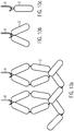
- a chain of sausages (individual sausages in a row) can be hung in loops on hooks 8 or several sausages can be picked up on a hook, for example in pairs, at a compartment, as in FIG Figure 10b or a single sausage can be hung from a loop, as in Figure 10c is shown.
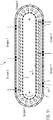
- the sausages produced can be divided into sausage groups 3, each sausage group comprising a certain number of hooks.
- the beginning and end of a sausage group can be displayed by a display device 26 or one or more hooks are left out between the sausage groups so that an operator can recognize the beginning and end of a sausage group. Color markings of the hooks can also be implemented.
- Fig. 2 shows sausage chains suspended in loops.
- a smoke stick 6 (either manually or automatically via a device for inserting a smoke stick or a handling system such as a robot) introduced into the loops and removed upwards.
- Fig. 12 shows a receiving hook in greater detail.
- the receiving hook 8 comprises a support arm 8a, which comprises a fastening section 3a, 3b at its upper end.
- the receiving hook can be fastened to the suspension device or to a holding device of the suspension device, here a hook guide 9, via the fastening section 3a, b.
- the fastening section 3a, 3b has a groove in which the hook guide 9 (see e.g. Fig. 7 ) runs.
- the hook guide 9 guides the hook in the transport direction T and carries the weight.
- the portion weight i.e. the weight per sausage produced (or a proportional value for several sausages) is to be determined in order to adjust or regulate the filling parameters of the filling machine 10 accordingly in the event of a deviation.
- a weighing device 4 is integrated into the suspension device 1 for this purpose.
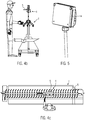
- FIG. 3-6c relates to a manual weighing system not according to the invention, in which an operator has to place or hang sausages on a weighing support 5 which is connected to a weighing cell 7.
- the load cell 7 is firmly connected to the suspension device 1 via a stand 20 (see exemplary embodiments in Figure 3-6c ).
- a sheet metal for weighing individual or connected sausages 2 is attached as a weighing support 5, such as in particular from the Fig. 3 , 4a-c emerges.
- the cradle support can be designed in such a way that a smoking stick can be hung on it, that is to say designed here in particular as a fork, as in FIG Figures 6a-c is shown.
- the hanging smoke stick can be placed on the fork 5, which is connected to the weighing cell 7.
- the weighing support 5, viewed in the vertical direction, is advantageously arranged in a plane above the circumferential suspension hook 8.
- the stand 20 is attached in the middle of the suspension device, ie here between the leading and returning tracks.
- the tripod 20 z. B. attached to a supporting beam 21 of the suspension device 1 running in the direction of transport. Because the weighing support 5 is located in an upper central area, the operator can handle the hooks and sausages while a weighing process is carried out at the same time in an upper area.
- this weighing device can be used for both sides, ie front side and rear side of the suspension device.
- the suspension device 1 has a display and operating unit 14, which is also attached to the suspension device 1 and, for example, in Figure 4a and 5 is shown in more detail.
- the display and operating unit 14 comprises in particular an input device for starting the weighing process and / or an input device for inputting a number of sausages to be weighed or for confirming that the number of sausages to be weighed is correct. For example, it is possible for the operator to be informed via the display 14 that he has to carry out a weighing process before the control 17 of the filling machine stops production because the weighing process has not been carried out.
- a complete group of sausages is not to be weighed on a smoking stick, the operator has to separate individual or connected portions from the group, the ends that are now open close and then place the portions on the weighing platform 5.
- the separation and closing can also be carried out automatically by a machine upstream of the suspension device or by a device integrated in the suspension device.
- the portions of the group are returned to production in order to ensure a high level of smoking stick utilization.
- the operator When weighing a certain number of sausages or when weighing the smoke stick hung with sausage loops, the operator must ensure that the number of sausages is correct, otherwise the measurement result or the regulation of the filling process will be incorrect.
- the operator can determine the number of portions before the weighing process and enter it into the display and operating unit 14. This is particularly advantageous since the display and operating unit 14, for example a touchscreen, is located directly on the suspension device. Alternatively, these values can also be entered on the operating unit of the filling machine. It is also possible that the display device already indicates how many sausages are to be weighed and the operator simply confirms the specific number of sausages to be weighed on the display and operating unit 14. It is also possible for the display and operating unit 14 to have an input device for starting the weighing process. When determining the weight manually, the suspension device is preferably stopped. The weighed individual sausages can, for example, be hung on the hooks again. The sausages weighed on a smoking stick can be fed to a subsequent process step.
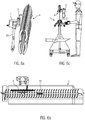
- FIGS 7-8 show an embodiment according to the present invention, which is integrated in a suspension device.
- the weighing device 4 is integrated into the guide track of the suspension device 1 for the circumferential suspension hook 8, that is, that at least one sausage can be weighed on at least one hook.
- the guide part 11 then takes on the function of the hook guide 9, that is to say it carries and guides the suspension hooks 8 running over it.
- the guide part 11 is then mechanically firmly connected to a load cell 7.
- the in Fig. 7 and 8th The exemplary embodiment shown is inserted in a weighing section A, the guide part 11, which is mechanically decoupled from the rest of the hook guide 9.
- the hook guide 9 has an upper and lower cutout 12a, b, in which respective guide sections 11a, 11b are inserted, and in particular also from Fig. 8 emerges.
- the grooves 3a, b of the hooks 8 run over the guide sections 11a, b when they are moved in the transport direction T.
- the Guide sections 11a, b are here connected to one another via a connecting section 11c which, as shown in FIG Fig. 8 is shown, is connected to the load cell 7.
- the hook guide 9 in the weighing section A can be completely removed and to be replaced by the decoupled guide part 11.
- Several weighing sections A can also be provided in an orbit.
- the hanging hooks 8 hung with sausages are transported over the guide section of the guide part 11 via a drive element 13, here in the form of a toothed belt. If the hook is in the area of the weighing section A, ie the decoupled guide part 11, its weight can be determined without the operator having to remove the product from the receiving hook 8 for the weighing process. One or more hooks up to a whole hook group, but also all hooks can be weighed, depending on the length of the weighing area A.
- the operator may have to separate individual or connected sausages in the group and separate the Close the ends of the portions so that the adjacent hanging hooks 8, which are not to be weighed and hung with sausage loops, have no influence on the weighing process.
- the separation and closing can also take place automatically by a machine upstream of the suspension device 1 or by a device integrated into the suspension device. So that the empty weight of the hooks is known, the hook weight of each individual hook or groups of hooks can be determined and set to "tare" via a reference run without products. In this way, only the sausages are weighed on the hook during a weighing process.
- an optical signal for example a display on the display and operating unit 14 can be displayed to the operator before the weighing process and inform that the operator is checking the hooks for completeness of the sausages got to.
- the hooks to be checked can, for example, be marked via an optical display or, for example, differ in color from the other hooks, so that the operator knows which hooks 8 he has to check.
- the operator can confirm the number or possibly correct it and / or trigger the weighing process with an input device, for example a button, on a display and control unit.
- the controller 17 of a filling machine detects the weight of the sausages on the hook or hooks through one or more weighing cells 7 the next time the corresponding hook or hooks are passed over the weighing section A.
- a measurement can be carried out continuously.
- the drive element 13 that is to say here the toothed belt, to stop in order to still bear the weight of the portions on the suspension hook 8 to determine more precisely.
- the weight signals or weight data are then evaluated in an evaluation unit 15, it being possible to determine the filling quantity or the filling weight per sausage or a value proportional thereto. If there is a deviation from a target value, the filling process or corresponding filling parameters can be adjusted or regulated.
- the hook is separated from the drive element for weighing.
- the drive element can stop.
- This version also corresponds to that in Figures 7-8 illustrated embodiment, but here the receiving hooks to be weighed can be uncoupled from the drive element 13 for weighing, for example by the guide part 11 being movable for uncoupling in a direction transverse to the transport direction T of the sausages, such that the receiving hook 8 moves away from the drive element 13 emotional.
- Corresponding can, as in particular in the Figures 9a, b, c is shown using a linear actuator, e.g. B. a lifting magnet 22 and a bearing unit 23 can be realized.
- the weighing cell 7 is mounted displaceably, for example, on the bearing unit 23, the bearing unit 23 being firmly connected to the suspension device 1.
- the load cell 7 including the guide part 11 and the receiving hook 8 covered with sausage loops is moved away from the drive element, here the drive belt 13, so that one or more hooks 8 are no longer connected to the drive element 13.
- Figure 9a shows a hook which is connected to the drive element 13 in the upper area.
- the drive element runs between the static hook guide 9 and the upper area of the hooks 8.
- Figure 9b shows the hook 8 moved away from the drive element 13.
- Figure 9c shows a plan view of the hooks, the guide part 11, the bearing unit and the lifting magnet.
- the structure of the weighing device 4 described above is suitable for a semi-automatic weighing system in which the operator can trigger the weighing process.
- the structure shown above is also particularly suitable for an automatic weighing system, i.e. for continuous weighing.
- the weighing process is carried out automatically at certain time intervals and / or according to a defined production quantity. It is also possible for the weight of the sausages on the hook to be recorded for all suspension hooks 8 and for each passage of the hook via a weighing section A. So that the determined weight data can be offset against the number of portions, e.g. a certain number of portions, which are used for evaluation, can be stored in the machine control.
- a corresponding number of hooks is stored in the control or, for example, it is calculated how many hooks are weighed in a measurement period.
- the weight signals and the number of sausages to be weighed can be fed to the evaluation unit 15.
- a deviation of a weight determined for one sausage (or for several sausages) from a nominal value can be determined and compared with a maximum permissible deviation.
- the filling parameters of the filling process are only adjusted if the maximum permissible deviation is not exceeded. If the check is OK, the weight signals are evaluated and, if necessary, a regulation of the filling process for more precise portion weights is initiated. If the check is not OK, another weighing process must be carried out.
- One or more hooks, a whole group of hooks or all hooks on the hanging device can be weighed. If the entire group of hooks is not to be weighed, the operator may have to separate individual or connected portions in the group and close the ends so that the hooks that are not to be weighed and hung with sausage loops have no influence on the weighing process.
- the operator can be informed of the separation and locking prior to the weighing process.
- the separation and closing can also be carried out automatically by a machine upstream of the suspension device or by a device integrated in the suspension device.
- the weighing process can also take place continuously in this exemplary embodiment or the drive element 13 can be stopped in order to determine the weight of the portions on the hook, as described above. Ideally, the hooks are also separated from the drive element 13 for determining the weight.
- the weight of at least one sausage on at least one suspension hook 8 is determined via the weighing device 4 in the suspension device 1.
- Weighing signals are passed to an evaluation unit 15, and filling parameters, in particular the conveyor output or the portion volume of the filling process, are adapted as a function of the recorded weight signals. This means that if, for example, the portion weight of a sausage is too low, the delivery rate per time of a pump is increased accordingly in order to compensate for the missing weight.
- the weighing device 4 according to the invention is completely integrated into the filling machine for sausage production and is firmly connected to the suspension device, so that no further installation space is required in the production hall. By mounting the weighing device within the suspension device, the weighing device 4 can be used flexibly in terms of location.
- the operator's workflow is less disturbed during weighing, since he can carry out the weighing process directly on the suspension device.
- a possibly optical display on a display and operating device 14 prevents additional production stops. As described above, no stopping is necessary in automatic operation. In a semi-automatic and automatic operation, the operator no longer has to remove products for weighing from the suspension device 1 and then add them again, but can thread a smoking stick through the sausage loops after the weighing process (without prior weighing (tare) of the smoke stick) and the one hung with sausage loops Place the smoke stick in the smoke trolley. This leads to a relief for the operator or to an increase in performance and a reduction in costs.
- an evaluation unit 15 in particular a corresponding software control, results in a completely integrated weighing system within a filling and portioning system for sausage products.
- the determination or control of the number of sausages can also be automated, ie that an optical device is provided (such as a camera system, for example or a proximity switch) or mechanical sensors (e.g. switching cams) to determine the number of hooks and / or sausages to be weighed.
- an optical device such as a camera system, for example or a proximity switch
- mechanical sensors e.g. switching cams
Landscapes
- Life Sciences & Earth Sciences (AREA)
- Engineering & Computer Science (AREA)
- Physics & Mathematics (AREA)
- General Physics & Mathematics (AREA)
- Wood Science & Technology (AREA)
- Zoology (AREA)
- Food Science & Technology (AREA)
- Meat, Egg Or Seafood Products (AREA)
- Chain Conveyers (AREA)
- Processing Of Meat And Fish (AREA)
Description
- Die Erfindung betrifft eine Aufhängevorrichtung, eine Füllmaschine sowie ein Betriebsverfahren zum Herstellen von Würsten gemäß den Oberbegriffen der Ansprüche 1, 8 und 9.
- Eine Aufhängevorrichtung gemäß dem Oberbegriff des Anspruchs 1 ist bereits aus der
EP 2 305 043 A1 bekannt, die bereits ebenfalls Aufhängehaken zeigt, über die das Gewicht einer Wurst bestimmt werden kann. - Auch die
WO 2015/15663 A1 - Bei der Herstellung von Würsten bzw. Wurstprodukten durch Füll- und Portioniersysteme werden Wursthüllen, z.B. Natur-, Kunst- oder Kollagendärme, mittels einer Füllmaschine, insbesondere Vakuumfüllmaschine, mit pastöser Masse gefüllt. Durch das Abdrehen des gefüllten Darms ergibt sich in der Abdrehlinie eine Wurstkette aus zusammenhängenden Einzelwürsten bzw. Portionen. Bei der Übergabe der Wurstkette auf eine Aufhängeeinheit werden vorgegebene Abteilstellen von Haken erfasst, so dass sich auf der Aufhängeeinheit aus der Wurstkette mehrere Wurstschleifen bilden (siehe z.B.
Fig. 10a ). Eine solche Schleife besteht aus mehreren Würsten (3-Loop, 4-Loop, inFig. 10a 6-Loop). Es ist aber auch möglich die Würste paarweise aufzuhängen (Fig. 10b ) oder Einzelwürste beispielsweise an einer Schlaufe auf einen Haken aufzuhängen (Fig. 10c ). - Dabei können mehrere Haken mit jeweiligen Würsten in sogenannten Wurstgruppen zusammengefasst werden, wie beispielsweise aus
Fig. 11 hervorgeht. Die Wurstketten werden am Gruppenübergang getrennt und die offenen Enden der Portionen werden, wenn nötig, verschlossen (geclipt, verknotet, verschweißt). Bei der Produktentnahme aus der Aufhängeeinheit wird beispielsweise ein Rauchstock in die Wurstschleifen einer Gruppe eingeführt (eingefädelt) und anschließend der mit der Wurstschleife behängte Rauchstock aus dem Haken für die weitere Verarbeitung entnommen, wie beispielsweise aus derFig. 2 hervorgeht. - Für eine Optimierung des Füllprozesses bzw. Produktionsablaufs mit dem Ziel, möglichst genaue Portionsgewichte, d.h. möglichst konstante Gewichte der Würste, zu erzielen, werden die Würste vor oder während der Produktentnahme in bestimmten Zeitabständen oder nach einer definierten Produktionsmenge mit Hilfe eines gesonderten Wägesystems gewogen. Dabei können einzelne oder zusammenhängende Würste oder komplett mit Wurstschleifen behängte Rauchstöcke gewogen werden. Hier können beispielsweise Stand-alone-Wägesysteme als Rauchstock-/Portionswaage verwendet werden. Das Platzangebot in der Produktionshalle ist allerdings begrenzt. Ein Stand-alone-Wägesystem benötigt zusätzlichen Platzbedarf neben dem eigentlichen Füll- und Portioniersystem. Der Maschinenbediener muss die Produkte entnehmen und zum Wägesystem laufen. Dies bedeutet eine Störung des eigentlichen Arbeitsablaufs für den Bediener und es kann zu längeren Produktionsunterbrechungen/-stopps kommen. Es gibt auch bereits Wägesysteme, die an der Produktionshallendecke befestigt sind. Eine entsprechende Platzierung bringt jedoch hohe Installationskosten mit sich. Der Aufstellungsort des Füll- und Portioniersystems ist nicht mehr flexibel. Auch an Produktionshallenwänden befestigte Wägesysteme sind nachteilig, da auch hier der Maschinenbediener die Produkte entnehmen und zum Wägesystem laufen muss. Teilweise ist nur eine Waage für mehrere Fülllinien und Maschinenbediener vorhanden. Dies bedeutet eine Störung des eigentlichen Arbeitsablaufs für den Bediener und es kann aufgrund von Wartezeiten zu Produktionsunterbrechungen bzw. - stopps kommen.
- Darüber hinaus können die in Wurstschleifen auf dem Rauchstock aufgehängten Würste durch den Transport zur Waage auf dem Rauchstock verrutschen, so dass kein gleichmäßiger Abstand zwischen den Würsten gewährleistet ist, was beispielsweise nachteilig bei nachfolgenden Behandlungsschritten, wie Räuchern etc. ist, da sich die Produkte hierbei nicht berühren dürfen.
- Hiervon ausgehend liegt der vorliegenden Erfindung die Aufgabe zugrunde, auf einfache Art und Weise die Portionsgenauigkeit der erzeugten Würste zu verbessern, wobei gleichzeitig der Produktionsablauf so wenig wie möglich gestört wird.
- Erfindungsgemäß wird diese Aufgabe durch die Merkmale der Ansprüche 1, 8 und 9 gelöst.
- Gemäß der vorliegenden Erfindung ist die Wägeeinrichtung in der Aufhängevorrichtung integriert. Somit entfällt der Transport der Würste von der Aufhängevorrichtung zur Wägeeinrichtung, was Produktionsunterbrechungen und -stopps verhindern oder zumindest wesentlich reduzieren kann. Somit kann der Füllprozess und der Produktionsablauf optimiert werden. Dadurch, dass die Wägeeinrichtung in der Aufhängeeinrichtung integriert ist, ist kein zusätzlicher Platz in der Produktionshalle für die Wägeeinrichtung notwendig. Dadurch, dass die Wägeeinrichtung in der Aufhängeeinrichtung integriert ist, entfallen zusätzliche Installationsarbeiten und Installationskosten. Insgesamt kann die Wägeeinrichtung kostengünstiger realisiert werden. Vorteilhafterweise ist damit die Wägeeinrichtung zusammen mit der Aufhängevorrichtung im Produktionsraum verfahrbar und ist nicht auf einen bestimmten Platz beschränkt. Dies bringt eine außerordentliche Flexibilität mit sich, da die Position der einzelnen Maschinen frei wählbar und veränderbar ist. Durch die integrierte Wägezelle wird der Arbeitsablauf der Bediener der Aufhängevorrichtung weniger gestört, da der Wiegevorgang direkt an der Aufhängevorrichtung durchgeführt werden kann.
- Die vorliegende Erfindung erlaubt jedoch nicht nur einen manuellen Wiegevorgang, sondern auch einen halbautomatischen oder automatischen Wiegevorgang, bei denen mindestens ein Aufnahmehaken mit einer Wägezelle verbunden ist, derart, dass das Gewicht der mindestens einen Wurst oder Wurstkette am Aufnahmehaken bestimmt werden kann. Das heißt, dass das Gewicht der mindestens einen Wurst auf mindestens einem Haken auf eine Wägezelle wirkt. Dabei kann der Haken über eine Einrichtung, die den Haken hält und sein Gewicht trägt, mit der Wägezelle verbunden sein. Vorzugsweise hat diese Einrichtung zum Halten des Gewichts auch noch eine Führungsfunktion für den Haken.
- Somit kann das Gewicht der mindestens einen Wurst auf mindestens einem Haken bestimmt werden, d.h. das Gewicht einer gewünschten Anzahl von Würsten, ohne dass diese vom Haken genommen werden müssen. Dies vereinfacht den Produktionsablauf wesentlich und führt zu einer außerordentlichen Leistungssteigerung und Kostenreduzierung. Es ist kein zusätzlicher Produktionsstopp, wie dies beispielsweise bei dem manuellen Wiegeverfahren vorteilhaft ist, notwendig. Da der Wiegevorgang in den Arbeitsablauf des Bedieners integriert wird, wird dieser wesentlich entlastet. Abhängig von der Länge eines Wägeabschnitts können so ein oder mehrere Haken bis zu einer ganzen Hakengruppe, die von einem Rauchstock abgenommen werden soll, gewogen werden. Ebenso ist es möglich, das Gewicht der gesamten Hakenführung zu bestimmen. Damit das Leergewicht der Haken bekannt ist, kann über eine Referenzfahrt ohne Produkte das Hakengewicht bestimmt und auf "Tara" gesetzt werden.
- Gemäß einem besonders bevorzugten Ausführungsbeispiel weist die Aufhängevorrichtung eine Hakenführung auf, an der die Aufnahmehaken auf ihrer Umlaufbahn umlaufen können. Die Hakenführung hat dabei die Funktion, die Haken auf ihrer Bahn zu führen und gleichzeitig das Gewicht der Haken zu tragen. Dabei kann die Hakenführung zumindest abschnittsweise mit einer Wägezelle verbunden sein. Ist beispielsweise die gesamte Hakenführung mit einer oder mehreren Wägezellen verbunden, so kann das Gewicht aller Würste, die sich zu einem bestimmten Messzeitpunkt auf der Aufhängevorrichtung befinden, bestimmt werden. Es ist aber auch möglich, dass das Gewicht nur in einem oder mehreren Wägeabschnitten der Hakenführung bestimmt wird. Dabei umfasst die Wägeeinrichtung ein in einem Wägeabschnitt der Hakenführung integriertes und von der Hakenführung entkoppeltes Führungsteil, an dem die Aufhängehaken in dem Wägeabschnitt geführt und gehalten werden können, wobei dieses Führungsteil mit der Wägezelle verbunden ist. Somit übernimmt das eingesetzte Führungsteil die Funktionen der Hakenführung in dem Wägeabschnitt. Dadurch, dass das Führungsteil in dem Wägeabschnitt von der Hakenführung entkoppelt ist, wird ausschließlich das Gewicht der Wurst oder der Würste, die an den Haken in diesem Wägeabschnitt angeordnet sind, bestimmt. Eine entsprechende Anordnung ist besonders kostengünstig, platzsparend und einfach zu realisieren. Beim Messen kann z.B. der Transport der Aufhängehaken für einen bestimmten Messzeitraum gestoppt werden und das Gewicht der Würste an den Haken, die im Wägeabschnitt angeordnet sind, bestimmt werden. Es ist aber auch möglich, kontinuierlich während des Prozesses das Gewicht von einem oder mehreren Haken, die in einem bestimmten Zeitintervall über den Wägeabschnitt fahren, zu bestimmen. Eine entsprechende Anordnung ermöglicht ein teilautomatisches Wägesystem, bei dem der Bediener selbst den Wägevorgang einleitet, aber auch ein automatisches Wägesystem, bei dem eine Steuerung den Wägevorgang einleitet und beendet.
- Gemäß einer besonderen Ausführungsform weist die umlaufende Hakenführung mindestens eine Aussparung auf, in die ein Führungsabschnitt des Führungsteils eingesetzt ist, wobei der Führungsabschnitt über einen Verbindungabschnitt mit der Wägezelle verbunden ist. Wenn eine Hakenführung verwendet wird, die den oberen Hakenbereich an zwei vertikal übereinander angeordneten Stellen führt, so ist es vorteilhaft, wenn in dem Wägeabschnitt in der Hakenführung eine obere und eine untere Aussparung vorgesehen sind, in denen jeweilige Führungsabschnitte eingesetzt sind, die dann die Funktion der eigentlichen Hakenführung übernehmen. Die jeweiligen von der restlichen Führung entkoppelten Führungsabschnitte können dann über einen Verbindungsabschnitt miteinander verbunden sein, wobei der Verbindungsabschnitt mit der Wägezelle verbunden ist. Es ist aber auch möglich, dass in dem Wägeabschnitt die Hakenführung komplett entfernt ist und das entkoppelte Führungsteil hier eingesetzt wird, um die Funktionen der Hakenführung zu übernehmen.
- Gemäß der vorliegenden Erfindung weist die Aufhängevorrichtung ein umlaufendes, mit den Aufhängehaken in Eingriff stehendes Antriebselement, z.B. einen Antriebsriemen, auf. Zum Wiegen werden die zu wiegenden Aufnahmehaken vom Antriebselement abgekoppelt. Insbesondere kann dazu beispielsweise das Führungsteil zum Auskoppeln in einer Richtung quer zur Transportrichtung der Würste bewegt werden, derart, dass sich der Haken von dem Antriebselement weg bewegt. Dadurch wird der Einfluss des Antriebselementes auf den Wiegevorgang ausgeschlossen. Somit ist ein noch exakteres Wiegen der einzelnen Würste möglich. Nach dem Wiegevorgang bewegt sich beispielsweise das Führungsteil wieder zurück, so dass die Aufhängehaken wieder mit dem Antriebselement verbunden sind.
- Der Wägeabschnitt weist eine Länge auf, derart, dass das Gewicht von mindestens einer Wurst an mindestens einem Aufhängehaken erfasst werden kann. Der Wägeabschnitt kann jedoch auch eine Länge aufweisen, so dass er mehrere mit Würsten behängte Aufhängehaken wiegen kann. Vorzugsweise können beispielsweise 1 bis 50 Aufhängehaken in dem Wägeabschnitt gewogen werden, wobei der Wägeabschnitt beispielsweise eine Länge von 20 mm bis 1500 mm aufweist. Somit kann beispielsweise das Gewicht einer gesamten Wurstgruppe, die von einem Rauchstock abgenommen wird, bestimmt werden.
- Es ist besonders vorteilhaft, wenn die Aufhängevorrichtung eine Anzeige- und Bedieneinheit umfasst und zwar eine Anzeigeeinheit, die zusätzlich zu der Anzeige- und Bedieneinheit der Füllmaschine vorgesehen ist und beispielsweise als Touchscreen ausgebildet ist. Vorzugsweise weist diese Anzeige- und Bedieneinheit eine Eingabeeinrichtung zum Starten des Wiegevorgangs auf und/oder eine Eingabeeinrichtung zum Eingeben einer Wurstanzahl der zu wiegenden Würste oder zum Bestätigen, dass die Anzahl der zu wiegenden Würste korrekt ist. Darüber hinaus kann die Anzeige- und Bedieneinheit auch dem Bediener anzeigen, dass ein Wiegevorgang durchgeführt werden muss oder einen Wiegezeitraum angeben. Die zusätzlich vorgesehene Anzeige- und Bedieneinheit bringt den Vorteil mit sich, dass insbesondere beim manuellen und halbautomatischen System stets gewährleistet ist, dass das gewogene Gewicht sich auf die korrekte Anzahl der Würste bezieht. Somit kann die Fehlerquote deutlich reduziert werden. Somit kann sichergestellt werden, dass keine falsche Regelung des Füllprozesses stattfindet. Durch die Auswertung der Gewichtsdaten kann dann eine Regelung des Füllprozesses erfolgen.
- Die Erfindung betrifft auch eine Füllmaschine mit der erfindungsgemäßen Aufhängevorrichtung nach mindestens einem der Ansprüche 1-7.
- Dabei kann die Wägeeinrichtung der Aufhängevorrichtung die Signale an eine Auswerteeinheit leiten, wobei die Steuerung der Füllmaschine derart ausgebildet ist, dass die Füllparameter des Füllprozesses, insbesondere die Förderwerkleistung und/oder das Portionsvolumen (d.h., dass Volumen, dass pro Zeiteinheit oder pro Portion von der Förderpumpe ausgestoßen wird) in Abhängigkeit der erfassten Wiegesignale angepasst werden können. Durch die erfindungsgemäße Aufhängevorrichtung mit der integrierten Wägeeinrichtung ist eine exakte Bestimmung des Portionsgewichts möglich, so dass die Füllparameter exakt geregelt bzw. eingestellt werden können. Da die Wägeeinrichtung in der Aufhängevorrichtung integriert ist, die in einer Fülllinie angeordnet ist, kann die Wägeeinrichtung auf einfache Art und Weise mit der Auswerteeinheit bzw. der Steuerung der Füllmaschine kommunizieren, ohne dass es störende Kabelverbindungen oder Signalstörungen zu einer gesonderten weiter entfernten Wägeeinrichtung gibt. Somit ist eine kompakte Anordnung möglich. Die Auswerteeinheit kann beispielsweise Teil der Steuerung der Füllmaschine sein oder aber ein gesondertes Modul, das mit der Füllmaschinensteuerung kommuniziert.
- Bei dem Betriebsverfahren zum Herstellen von Würsten gemäß der vorliegenden Erfindung wird für mindestens eine Wurst an mindestens einem Aufhängehaken das Gewicht über die Wägeeinrichtung an der Aufhängevorrichtung bestimmt. Wiegesignale werden von der Wägeeinrichtung bzw. deren Wägezelle an eine Auswerteeinheit geleitet. Eine entsprechende Auswerteeinheit kann das Gewicht einer Einzelwurst oder einen dazu proportionalen Wert (z.B. für mehrere Würste) ermitteln und mit einem Sollwert vergleichen. Bei Abweichung können Füllparameter, insbesondere die Förderleistung und/oder das Portionsvolumen des Füllprozesses in Abhängigkeit der erfassten Gewichtssignale angepasst bzw. geregelt werden. Somit kann eine exakte Portionsgenauigkeit realisiert werden.
- Gemäß dem Verfahren kann das Gewicht der mindestens einen Wurst über eine Wägezelle bestimmt wird, während sie auf mindestens einem Haken hängt. Dies ist besonders vorteilhaft, da der Bediener dann nicht die Würste extra von den Haken nehmen muss und die Würste nach dem Wiegen zur Weiterverarbeitung nicht wieder auf die Haken hängen muss und somit der Produktionsablauf dadurch nicht gestört wird.
- Vorteilhafterweise ist eine Anzeige vorgesehen, die anzeigt, dass eine Wägung durchzuführen ist. Ein entsprechender Wägezeitpunkt wird durch eine Steuerung der Füllmaschine vorgegeben. Um eine exakte Messung durchzuführen, ist vorteilhafterweise eine Eingabeeinrichtung vorgesehen, über die die Anzahl der zu wiegenden Würste eingegeben wird und/oder über die die korrekte Anzahl der zu wiegenden Würste eingegeben oder bestätigt werden kann. Vorzugsweise ist auch eine Einrichtung vorgesehen, über die der Wiegevorgang manuell gestartet wird.
- Es ist aber auch möglich, dass der Wiegevorgang automatisch, vorzugsweise in bestimmten Zeitintervallen oder nach einer definierten Produktionsmenge durchgeführt wird. Ein entsprechendes automatisches Betriebsverfahren ist besonders vorteilhaft, da die Produktion kontinuierlich erfolgen kann und Fehler durch Bediener ausgeschlossen werden können. Ein automatischer Wiegevorgang führt zu deutlichen Leistungssteigerungen und Kostenreduzierung. Ein Wiegen im Durchlauf und eine kontinuierliche Auswertung dieser Wiegesignale ermöglicht eine kontinuierliche Anpassung bzw. Regelung der Füllparameter.
- Gemäß einem bevorzugten Ausführungsbeispiel werden der Auswerteeinheit Gewichtssignale zugeführt sowie eine Anzahl gewogener Würste, wobei z.B. das Gewicht pro Wurst bestimmt wird (oder ein dazu proportionaler Wert z.B. für mehrere Würste) und mit einem Sollwert verglichen wird. Es werden nur dann die Füllparameter des Füllprozesses angepasst, wenn eine maximal zulässige Abweichung nicht überschritten wird. Somit kann sichergestellt werden, dass Fehler in der Anzahl der für die Auswertung herangezogenen Würste nicht zu einer unkorrekten Regelung des Füllvorgangs führen. Somit können beispielsweise Zählfehler von Bedienern kompensiert werden, aber auch beim automatischen Prozess, bei dem über eine Steuerung bestimmt wird, welche Anzahl von Würsten die Grundlage für die Auswertung darstellen, können Fehler, insbesondere am Produktionsanfang oder aber bedingt durch Wurstplatzer, Produktionsfehlern kompensiert werden. Die ermittelte Abweichung kann zum Beispiel mit einem ersten Grenzwert und einem zweiten Grenzwert verglichen werden. Bei Überschreiten eines ersten Grenzwertes soll dann das Portionsvolumen nachgeregelt werden- bei Überschreiten eines zweiten Grenzwertes, der größer ist als der erste Grenzwert soll nicht nachgeregelt werden, sondern eine Fehlermeldung ausgegeben werden oder ein weiterer Wiegevorgang mit der richtigen Stückzahl erfolgen. Dieser Fall tritt vorwiegend beim automatischen Betrieb auf.Die vorliegende Erfindung wird nachfolgend unter Bezugnahme folgender Figuren näher erläutert:
- Fig. 1
- zeigt eine seitlich Gesamtansicht einer Füllmaschine mit einer Aufhängevorrichtung gemäß der vorliegenden Erfindung.
- Fig. 2
- zeigt einen Ausschnitt einer Aufhängevorrichtung mit mehreren Aufnahmehaken, an denen Wurstketten in Schlaufen aufgehängt sind.
- Fig. 3
- zeigt eine perspektivische Darstellung eines Beispiels einer Wägeeinrichtung, die nicht der vorliegenden Erfindung entspricht.
- Fig. 4a
- zeigt schematisch eine perspektivische Darstellung einer Aufhängevorrichtung, die nicht der vorliegenden Erfindung entspricht.
- Fig. 4b
- zeigt eine Vorderansicht des in
Fig. 4a gezeigtennicht erfindungsgemäßen Beispiels . - Fig. 4c
- zeigt eine Draufsicht auf das in
Fig. 4a undb gezeigte nicht erfindungsgemäße Beispiel - Fig. 5
- zeigt eine Anzeige für eine Aufhängevorrichtung gemäß der vorliegenden Erfindung.
- Fig. 6a
- zeigt eine nicht erfindungsgemäße Wägeeinrichtung für eine Aufhängevorrichtung.
- Fig. 6b
- zeigt die in
Fig. 6a dargestellte Wägeeinrichtung in der Aufhängevorrichtung in einer Draufsicht. - Fig. 6c
- zeigt die in
Fig. 6a dargestellte Aufhängeeinrichtung aus einer Vorderansicht. - Fig. 7
- zeigt eine Teilansicht einer Aufhängevorrichtung gemäß einem weiteren Ausführungsbeispiel der vorliegenden Erfindung.
- Fig. 7a
- zeigt einen vergrößerten Ausschnitt der
Fig. 7 . - Fig. 7b
- zeigt eine Draufsicht auf den in
Fig. 7a gezeigten Ausschnitt. - Fig. 7c
- zeigt eine Seitenansicht eines Hakens mit Wägeeinrichtung gemäß dem in
Fig. 7a ,b gezeigten Ausführungsbeispiel der vorliegenden Erfindung. - Fig. 8
- zeigt schematisch die Rückseite des in den
Fig. 7a-c gezeigten Ausführungsbeispiels. - Fig. 9a
- zeigt eine Seitenansicht gemäß einem bevorzugten Ausführungsbeispiel einer Aufhängevorrichtung, bei dem ein Aufnahmehaken mit einem Antriebselement verbunden ist.
- Fig. 9b
- zeigt das in
Fig. 9a gezeigte Ausführungsbeispiel, bei dem ein Haken nicht mit dem Antriebselement verbunden ist. - Fig. 9c
- ist eine Draufsicht auf
Fig. 9b . - Fig. 10a
- zeigt eine in Schleifen aufgehängte Wurstkette.
- Fig. 10b
- zeigt Würste, die paarweise an einer Abteilstelle an dem Haken aufgenommen sind.
- Fig. 10c
- zeigt schematisch eine Wurstportion an einer Schlaufe an einem Haken.
- Fig. 11
- zeigt eine Draufsicht auf eine Aufhängevorrichtung, bei der unterschiedliche Wurstgruppen dargestellt sind.
- Fig. 12
- zeigt schematisch eine Seitenansicht eines Aufnahmehakens.
-
Fig. 1 zeigt die Seitenansicht einer Füllmaschine 10 gemäß der vorliegenden Erfindung, mit der in bekannter Weise Wursthüllen mit pastösem Gut über ein Füllrohr 18 befüllt werden können. Die Würste 2 werden über eine Fördereinrichtung 19 in Transportrichtung T gefördert. Hier wird als Fördereinrichtung 19 eine sogenannte Längeneinheit, die zwei umlaufende Transportbänder umfasst, verwendet. Die gefüllten Würste können an bestimmten Stellen abgedreht und unterteilt werden. Es ist auch möglich, einen kontinuierlich gefüllten Wurststrang herzustellen, der keine Abdreh- bzw. Unterteilungsstellen aufweist. Die hergestellten Würste können auch an bestimmten Stellen voneinander abgetrennt werden, so dass Wurstketten mit mehreren Würsten erzeugt werden, die dann in Gruppen auf Aufnahmehaken 8 aufgehängt werden können. Wie ausFig. 1 hervorgeht, befindet sich in Transportrichtung hinter dem Füllrohr bzw. hier hinter der Transporteinrichtung 19 eine Aufhängevorrichtung 1, die in bekannter Weise die gefüllten Würste oder Wurstketten mit Hilfe von Aufnahmehaken 8 automatisch in Schleifen aufhängt. Die Aufhängevorrichtung 1 kann auch direkt hinter dem Füllrohr angeordnet sein. Dabei werden die Aufnahmehaken 8 über ein Antriebselement 13 beispielsweise in Form eines Riemens, einer Kette etc. in Transportrichtung bewegt, wobei die Aufnahmehaken 8 nach der Entnahme der Würste im Kreis wieder zur Aufnahmestelle zurück gefördert werden. Dabei kann eine Wurstkette (Einzelwürste in Reihe) in Schleifen auf Haken 8 aufgehängt werden oder aber es können mehrere Würste z.B. paarweise an einer Abteilstelle an einem Haken aufgenommen werden, wie inFig. 10b gezeigt ist oder aber eine einzelne Wurst kann an einer Schlaufe aufgehängt werden, wie inFig. 10c gezeigt ist. Wie ausFig. 11 hervorgeht, können die produzierten Würste in Wurstgruppen 3 eingeteilt werden, wobei jede Wurstgruppe eine bestimmte Hakenanzahl umfasst. Anfang und Ende eine Wurstgruppe können durch eine Anzeigeeinrichtung 26 angezeigt werden oder aber es wird ein oder mehrere Haken zwischen den Wurstgruppen ausgespart, damit ein Bediener Anfang und Ende einer Wurstgruppe erkennen kann. Auch farbliche Markierungen der Haken sind realisierbar. -
Fig. 2 zeigt in Schleifen aufgehängte Wurstketten. Zur Entnahme und zum Weiterbehandeln der Würste wird, wie ausFig. 2 ersichtlich, ein Rauchstock 6 (entweder manuell oder automatisch über eine Vorrichtung zum Einschieben eines Rauchstocks oder ein Handhabungssystem, wie etwa einen Roboter) in die Schleifen eingeführt und nach oben entnommen. -
Fig. 12 zeigt einen Aufnahmehaken in größerem Detail. Der Aufnahmehaken 8 umfasst einen Tragarm 8a, der an seinem oberen Ende einen Befestigungsabschnitt 3a, 3b umfasst. Über den Befestigungsabschnitt 3a,b kann der Aufnahmehaken an der Aufhängeeinrichtung bzw. an einer Halteeinrichtung der Aufhängeeinrichtung, hier einer Hakenführung 9, befestigt werden. Dabei weist z.B. der Befestigungsabschnitt 3a, 3b eine Nut auf, in der die Hakenführung 9 (siehe z.B.Fig. 7 ) läuft. Die Hakenführung 9 führt den Haken in Transportrichtung T und trägt das Gewicht. - Gemäß der vorliegenden Erfindung soll nun das Portionsgewicht, d.h. das Gewicht pro produzierter Wurst (oder ein proportionaler Wert für mehrere Würste), bestimmt werden, um bei Abweichung die Füllparameter der Füllmaschine 10 entsprechend anzupassen oder zu regeln. Gemäß der vorliegenden Erfindung ist dazu eine Wägeeinrichtung 4 in die Aufhängevorrichtung 1 integriert.
- Das in den
Fig. 3-6c bezieht sich auf ein manuelles nicht erfindungsgemäßes Wägesystem, bei dem ein Bediener Würste auf eine Wiegeauflage 5, die mit einer Wägezelle 7 verbunden ist, legen oder hängen muss. Hier ist die Wägezelle 7 über ein Stativ 20 fest mit der Aufhängevorrichtung 1 verbunden (siehe Ausführungsbeispiele inFig. 3-6c ). Auf der Wägezelle 7 wird z.B. als Wiegeauflage 5 ein Blech zum Wiegen von einzelnen oder zusammenhängenden Würsten 2 befestigt, wie insbesondere aus denFig. 3 ,4a-c hervorgeht. Alternativ dazu kann die Wiegeauflage derart ausgestaltet sein, dass ein Rauchstock daran aufgehängt werden kann, d.h. hier insbesondere als Gabel ausgebildet sein, wie in derFig. 6a-c dargestellt ist. Der behängte Rauchstock kann auf die Gabel 5 aufgelegt werden, die mit der Wägezelle 7 verbunden ist. - Vorteilhafterweise ist die Wiegeauflage 5 in Vertikalrichtung betrachtet in einer Ebene über den umlaufenden Aufhängehaken 8 angeordnet. In diesem Ausführungsbeispiel ist dazu das Stativ 20 in der Mitte der Aufhängevorrichtung, d.h. hier zwischen der vorlaufenden und rücklaufenden Bahn befestigt. Hier ist das Stativ 20 z. B. an einem in Transportrichtung verlaufenden Tragebalken 21 der Aufhängevorrichtung 1 befestigt. Dadurch, dass sich die Wiegeauflage 5 in einem oberen mittleren Bereich befindet, kann der Bediener an den Haken und Würsten hantieren, während gleichzeitig in einem oberen Bereich ein Wiegevorgang erfolgt. Darüber hinaus kann, wie z.B. aus
Fig. 4a und4b hervorgeht, diese Wägeeinrichtung für beide Seiten, d.h. vordere Seite und hintere Seite der Aufhängevorrichtung, verwendet werden. - Weiter weist die Aufhängevorrichtung 1 eine Anzeige- und Bedieneinheit 14 auf, die ebenfalls an der Aufhängevorrichtung 1 befestigt ist und beispielsweise in
Fig. 4a und5 näher dargestellt ist. Die Anzeige- und Bedieneinheit 14 umfasst insbesondere eine Eingabeeinrichtung zum Starten des Wiegevorgangs und/oder eine Eingabeeinrichtung zum Eingeben einer Wurstanzahl der zu wiegenden Würste oder zum Bestätigen, dass die Anzahl der zu wiegenden Würste korrekt ist. So ist es beispielsweise möglich, dass über die Anzeige 14 dem Bediener mitgeteilt wird, dass er einen Wiegevorgang durchführen muss, bevor es über die Steuerung 17 der Füllmaschine zu einem Produktionsstopp wegen nicht durchgeführtem Wiegevorgang kommt. Wenn nicht eine komplette Wurstgruppe auf einem Rauchstock gewogen werden soll, muss der Bediener einzelne oder zusammenhängende Portionen aus der Gruppe heraustrennen, die nun offenen Enden verschließen und die Portionen dann auf die Wiegeauflage 5 ablegen. Das Trennen und Verschließen kann auch durch eine der Aufhängevorrichtung vorgelagerte Maschine oder durch eine in die Aufhängevorrichtung integrierte Vorrichtung automatisch erfolgen. Nach dem Wiegevorgang werden die Portionen der Gruppe wieder der Produktion zugeführt, um eine hohe Rauchstockauslastung zu gewährleisten. Beim Wiegen einer bestimmten Anzahl an Würsten oder beim Wiegen des mit Wurstschleifen behängten Rauchstocks muss der Bediener auf die richtige Anzahl an Würsten achten, da sonst das Messergebnis bzw. die Regelung des Füllprozesses falsch ist. Gemäß einem bevorzugten Ausführungsbeispiel kann der Bediener die Anzahl der Portionen vor dem Wiegevorgang ermitteln und in die Anzeige- und Bedieneinheit 14 eingeben. Dies ist besonders vorteilhaft, da sich die Anzeige- und Bedieneinheit 14, beispielsweise ein Touchscreen, direkt an der Aufhängevorrichtung befindet. Alternativ können diese Werte auch an der Bedieneinheit der Füllmaschine eingegeben werden. Es ist auch möglich, dass über die Anzeigeeinrichtung bereits angegeben wird, wie viele Würste zu wiegen sind und der Bediener an der Anzeige- und Bedieneinheit 14 einfach die bestimmte Anzahl der zu wiegenden Würste bestätigt. Es ist auch möglich, dass die Anzeige- und Bedieneinheit 14 eine Eingabeeinrichtung aufweist zum Starten des Wiegevorgangs. Bei der manuellen Gewichtsbestimmung wird die Aufhängevorrichtung vorzugsweise gestoppt. Die gewogenen Einzelwürste können beispielsweise wieder auf die Haken gehängt werden. Die auf einem Rauchstock gewogenen Würste können einem nachfolgenden Prozessschritt zugeführt werden. -
Fig. 7-8 zeigen ein Ausführungsbeispiel gemäß der vorliegenden Erfindung, das in einer Aufhängevorrichtung integriert ist. Bei dem in denFig. 7-8 gezeigten Ausführungsbeispiel ist die Wägeeinrichtung 4 in die Führungsbahn der Aufhängevorrichtung 1 für die umlaufenden Aufhängehaken 8 integriert, d.h., dass mindestens eine Wurst an mindestens einem Haken gewogen werden kann. Wie noch näher ausgeführt wird, bedeutet dies, dass an einem Abschnitt die Hakenführung 9 entfernt oder ausgespart ist und die fehlende Führung durch ein Führungsteil 11 ersetzt wird. Das Führungsteil 11 übernimmt dann die Funktion der Hakenführung 9, d.h. es trägt und führt die darüberlaufenden Aufhängehaken 8. Das Führungsteil 11 ist dann mechanisch fest mit einer Wägezelle 7 verbunden. - Bei dem in
Fig. 7 und8 gezeigten Ausführungsbeispiel ist in einem Wägeabschnitt A das Führungsteil 11 eingesetzt, das von der restlichen Hakenführung 9 mechanisch entkoppelt ist. Bei diesem konkreten Ausführungsbeispiel weist die Hakenführung 9 eine obere und untere Aussparung 12a,b auf, in denen jeweilige Führungsabschnitte 11a, 11b eingesetzt sind, wie insbesondere auch ausFig. 8 hervorgeht. Die Nuten 3a,b der Haken 8 laufen über die Führungsabschnitte 11a,b, wenn sie in Transportrichtung T bewegt werden. Die Führungsabschnitte 11a,b sind hier miteinander über einen Verbindungsabschnitt 11c verbunden, der, wie ausFig. 8 hervorgeht, mit der Wägezelle 7 verbunden ist. Dies ist nur ein bevorzugtes Ausführungsbeispiel. Es ist auch möglich, dass in dem Wägeabschnitt A die Hakenführung 9 komplett entfernt ist und durch das entkoppelte Führungsteil 11 ersetzt wird. In einer Umlaufbahn können auch mehrere Wägeabschnitte A vorgesehen sein. - Zur Gewichtsbestimmung werden die mit Würsten behängten Aufhängehaken 8 über ein Antriebselement 13, hier in Form eines Zahnriemens, über den Führungsabschnitt des Führungsteils 11 transportiert. Befindet sich der Haken im Bereich des Wägeabschnitts A, d.h. des entkoppelten Führungsteils 11, kann sein Gewicht bestimmt werden, ohne dass der Bediener das Produkt für den Wiegevorgang vom Aufnahmehaken 8 nehmen muss. Es können ein oder mehrere Haken bis zu einer ganzen Hakengruppe, aber auch alle Haken gewogen werden, abhängig von der Länge des Wiegebereichs A. Wenn nicht die ganze Hakengruppe gewogen werden soll, muss der Bediener eventuell einzelne oder zusammenhängende Würste in der Gruppe trennen und die Enden der Portionen verschließen, damit die angrenzenden nicht zu wiegenden und mit Wurstschleifen behängten Aufhängehaken 8 keinen Einfluss auf den Wiegevorgang haben. Das Trennen und Verschließen kann auch durch eine der Aufhängevorrichtung 1 vorgelagerte Maschine oder durch eine in die Aufhängevorrichtung integrierte Vorrichtung automatisch erfolgen. Damit das Leergewicht der Haken bekannt ist, kann über eine Referenzfahrt ohne Produkte das Hakengewicht eines jeden einzelnen Hakens oder auch von Hakengruppen bestimmt und auf "Tara" gesetzt werden. Somit werden bei einem Wiegevorgang nur die Würste auf den Haken gewogen. Um sicherzustellen, dass die Aufhängehaken 8 die richtige Anzahl an Würsten tragen, kann dem Bediener vor dem Wiegevorgang ein optisches Signal, z.B. eine Anzeige auf der Anzeige- und Bedieneinheit 14, angezeigt werden und mitteilen, dass der Bediener die Haken auf Vollständigkeit der Würste prüfen muss. Die zu prüfenden Haken können beispielsweise über eine optische Anzeige markiert werden oder z.B. sich farblich von den anderen Haken unterscheiden, so dass der Bediener weiß, welche Haken 8 er kontrollieren muss. Nach der Kontrolle und bei richtiger Anzahl der Portionen auf den Aufnahmehaken kann der Bediener die Anzahl bestätigen oder eventuell korrigieren und/oder mit einer Eingabeeinrichtung, z.B. einem Taster, auf einer Anzeige- und Bedieneinheit den Wiegevorgang auslösen. Nach der Auslösung erfasst die Steuerung 17 einer Füllmaschine bei der nächsten Überfahrt des oder der entsprechenden Haken über den Wägeabschnitt A das Gewicht der Würste auf dem oder den Haken durch eine oder mehrere Wägezellen 7. Eine Messung kann kontinuierlich erfolgen. Es ist aber auch möglich, dass das Antriebselement 13, d.h. hier der Zahnriemen, stoppt, um das Gewicht der Portionen auf den Aufhängehaken 8 noch genauer zu ermitteln. Die Gewichtssignale bzw. Gewichtsdaten werden dann in einer Auswerteeinheit 15 ausgewertet, wobei die Füllmenge bzw. das Füllgewicht pro Wurst oder ein dazu proportionaler Wert ermittelt werden kann. Bei Abweichung von einem Sollwert kann der Füllprozess bzw. entsprechende Füllparameter angepasst oder geregelt werden.
- Gemäß der Erfindung wird zum Wiegen der Haken vom Antriebselement getrennt. Dazu kann das Antriebselement stoppen. Diese Ausführung entspricht ebenfalls dem in den
Fig. 7-8 dargestellten Ausführungsbeispiel, wobei hier jedoch zum Wiegen die zu wiegenden Aufnahmehaken vom Antriebselement 13 abgekoppelt werden können, indem z.B. das Führungsteil 11 zum Auskoppeln in einer Richtung quer zur Transportrichtung T der Würste bewegbar ist, derart, dass sich der Aufnahmehaken 8 von dem Antriebselement 13 weg bewegt. Entsprechendes kann, wie insbesondere in denFig. 9a,b,c dargestellt ist, mit Hilfe eines Linearaktuators, z. B. eines Hubmagneten 22 und einer Lagereinheit 23 realisiert werden. Dabei ist die Wägezelle 7 beispielsweise auf der Lagereinheit 23 verschiebbar gelagert, wobei die Lagereinheit 23 fest mit der Aufhängevorrichtung 1 verbunden ist. Über den oben genannten Hubmagneten 22 wird die Wägezelle 7 einschließlich dem Führungsteil 11 und den mit Wurstschleifen behängten Aufnahmehaken 8 von dem Antriebselement, hier dem Antriebsriemen 13, weg bewegt, so dass ein oder mehrere Haken 8 nicht mehr mit dem Antriebselement 13 verbunden sind. -
Fig. 9a zeigt einen Haken, der mit dem Antriebselement 13 im oberen Bereich verbunden ist. Das Antriebselement läuft zwischen der statischen Hakenführung 9 und dem oberen Bereich der Haken 8. -
Fig. 9b zeigt den von dem Antriebselement 13 weg bewegten Haken 8. -
Fig. 9c zeigt eine Draufsicht auf die Haken, das Führungsteil 11, die Lagereinheit und den Hubmagneten. Durch das Trennen des Hakens von dem Antriebselement 13 wird ein Einfluss des Antriebselements 13 auf den Wiegevorgang ausgeschlossen. Damit dies umgesetzt werden kann, kann das Antriebselement 13 stoppen, bevor der Magnet 22 eine Bewegung auslöst. Nach dem Wiegevorgang bewegt sich die Wägezelle 7 inklusive Führungsteil 11, Haken 8 und - Würste 2 auf der Lagereinheit zurück, so dass der oder die Haken wieder mit dem Antriebselement 13 verbunden sind und weiter transportiert werden können.
- Der zuvor beschriebene Aufbau der Wägeeinrichtung 4 ist für ein teilautomatisches Wägesystem geeignet, bei dem der Bediener den Wiegevorgang auslösen kann. Der zuvor gezeigte Aufbau ist aber auch ganz besonders geeignet für ein automatisches Wägesystem, d.h. zum Wiegen im Durchlauf. Beim automatischen Wägesystem muss der Bediener keinen Wiegevorgang auslösen. Der Wiegevorgang wird in bestimmten Zeitabständen und/oder nach einer definierten Produktionsmenge automatisch durchgeführt. Ebenso ist es möglich, dass bei allen Aufhängehaken 8 und bei jeder Überfahrt der Haken über einen Wägeabschnitt A das Gewicht der Würste auf den Haken erfasst wird. Damit die ermittelten Gewichtsdaten mit der Anzahl der Portionen verrechnet werden können, kann z.B. in der Maschinensteuerung eine bestimmte Anzahl an Portionen, die zur Auswertung herangezogen werden, hinterlegt sein. In der Steuerung wird dazu eine entsprechende Anzahl von Haken hinterlegt oder aber z.B. berechnet, wieviele Haken in einem Messzeitraum gewogen werden. Der Auswerteeinheit 15 können die Gewichtssignale zugeführt werden und die Anzahl der zu wiegenden Würste. Eine Abweichung eines für eine Wurst (oder für mehrere Würste) ermittelten Gewichts von einem Sollwert kann bestimmt werden und mit einer maximal zulässigen Abweichung verglichen werden. Die Füllparameter des Füllprozesses werden nur dann angepasst, wenn die maximal zulässige Abweichung nicht überschritten wird. Ist die Prüfung in Ordnung, werden die Gewichtssignale ausgewertet und gegebenenfalls eine Regelung des Füllprozesses für genauere Portionsgewichte veranlasst. Ist die Prüfung nicht in Ordnung, muss ein weiterer Wiegevorgang durchgeführt werden.
- Es können ein oder mehrere Haken, eine ganze Hakengruppe oder alle Haken auf der Aufhängevorrichtung gewogen werden. Wenn nicht die ganze Hakengruppe gewogen werden soll, muss der Bediener eventuell einzelne oder zusammenhängende Portionen in der Gruppe trennen und die Enden verschließen, damit die nicht zu wiegenden, mit Wurstschleifen behängten Haken keinen Einfluss auf den Wiegevorgang haben. Durch ein z.B. optisches Signal oder eine Anzeige auf einer Anzeige- und Bedieneinheit kann der Bediener auf das Trennen und Verschließen vor dem Wiegevorgang hingewiesen werden. Das Trennen und Verschließen kann auch durch eine der Aufhängevorrichtung vorgelagerte Maschine oder durch eine in die Aufhängevorrichtung integrierte Vorrichtung automatisch erfolgen. Der Wiegevorgang kann auch in diesem Ausführungsbeispiel im Durchlauf stattfinden oder das Antriebselement 13 kann gestoppt werden, um das Gewicht der Portionen auf den Haken zu ermitteln, wie zuvor beschrieben. Idealerweise werden nämlich auch hier die Haken vom Antriebselement 13 zur Gewichtsbestimmung getrennt.
- Bei dem erfindungsgemäßen Betriebsverfahren wird also für mindestens eine Wurst an mindestens einem Aufhängehaken 8 das Gewicht über die Wägeeinrichtung 4 in der Aufhängevorrichtung 1 bestimmt. Wiegesignale werden an eine Auswerteeinheit 15 geleitet und Füllparameter, insbesondere Förderwerksleistung bzw. das Portionsvolumen des Füllprozesses werden in Abhängigkeit der erfassten Gewichtssignale angepasst. Das heißt, wenn beispielsweise das Portionsgewicht einer Wurst zu gering ist, wird die Fördermenge pro Zeit einer Pumpe entsprechend heraufgesetzt um das fehlende Gewicht zu kompensieren. Die erfindungsgemäße Wiegeeinrichtung 4 ist vollständig in die Füllmaschine zur Wurstproduktion integriert und fest mit der Aufhängevorrichtung verbunden, so dass kein weiterer Bauraum in der Produktionshalle benötigt wird. Durch die Montage der Wägeeinrichtung innerhalb der Aufhängevorrichtung ist die Wägeeinrichtung 4 örtlich flexibel einsetzbar. Durch die integrierte Wägeeinrichtung 4 wird der Arbeitsablauf der Bediener beim Wiegen weniger gestört, da er den Wiegevorgang direkt an der Aufhängevorrichtung durchführen kann. Eine gegebenenfalls optische Anzeige auf einer Anzeige- und Bedieneinrichtung 14 verhindert zusätzliche Produktionsstopps. Wie zuvor beschrieben, ist beim automatischen Betrieb kein Anhalten notwendig. Bei einem teilautomatischen und automatischen Betrieb muss der Bediener keine Produkte mehr zum Wiegen aus der Aufhängevorrichtung 1 entfernen und danach wieder hinzufügen, sondern kann einen Rauchstock nach dem Wiegevorgang (ohne vorheriges Wiegen (Tara) des Rauchstocks) durch die Wurstschleifen einfädeln und den mit Wurstschleifen behängten Rauchstock in den Rauchwagen ablegen. Dies führt zu einer Entlastung der Bediener bzw. zu einer Leistungssteigerung und Kostenreduzierung.
- Durch die Auswertung und Regelung der Gewichtssignale durch eine Auswerteeinheit 15, insbesondere eine entsprechende Softwaresteuerung, ergibt sich ein vollständig integriertes Wägesystem innerhalb eines Füll- und Portioniersystems für Wurstprodukte.
- Zuvor wurde das Entkoppeln der Aufnahmehaken 8 vom Antriebselement 13 durch das linear bewegliche Führungsteil 11 beschrieben. Gleichermaßen sind jedoch andere Auskopplungsmechanismen durch Drehbewegung, Kurvenbahn etc. kraft- und/oder formschlüssig denkbar. Alternativ zu dem in dem zuvor genannten Ausführungsbeispiel verwendeten Hubmagneten kann selbstverständlich auch ein anderes Stellglied zum Abkoppeln des mindestens einen Hakens vom Antriebselement verwendet werden. Erfolgt die Mitnahme der Haken durch ein Antriebselement (Riemen, Ketten oder Ähnliches) mit flexiblen Schlitzen/Nuten, so kann eine Entkopplung in einer Umlenkung stattfinden, da sich durch das Spreizen der Schlitze/Nuten in der Umlenkung die Schlitz-/Nutbreite vergrößert und somit die Reibung zwischen den Haken und dem Antriebselement reduziert. Die Ermittlung bzw. Kontrolle der Anzahl der Würste kann auch automatisiert werden, d.h. dass eine optische Einrichtung vorgesehen ist (wie z.B. ein Kamerasystem oder ein Näherungsschalter) oder mechanische Sensoren (z.B. Schaltnocken) zum Ermitteln der Anzahl der Haken und/oder Würste, die gewogen werden sollen.
Claims (12)
- Aufhängevorrichtung (1) zum Aufhängen von Würsten (2), insbesondere Wurstketten, mit mehreren umlaufenden Aufhängehaken (8), wobei
die Aufhängevorrichtung (1) eine integrierte Wägeeinrichtung (4) zum Wiegen mindestens einer Wurst (2) oder mindestens einer Wurstkette (2) umfasst,
wobei mindestens ein Aufnahmehaken (8) mit einer Wägezelle (7) verbunden ist, derart, dass das Gewicht der mindestens einen Wurst oder Wurstkette am Aufnahmehaken (8) bestimmt werden kann, dadurch gekennzeichnet, dass die Aufhängevorrichtung (1) ein umlaufendes, mit den Aufhängehaken (8) in Eingriff stehendes Antriebselement (13) aufweist, wobei zum Wiegen die zu wiegenden Aufnahmehaken vom Antriebselement (13) abgekoppelt werden können. - Aufhängevorrichtung (1) nach Anspruch 1, dadurch gekennzeichnet, dass die Aufhängevorrichtung (1) eine Hakenführung (9,11) aufweist, an der die Aufnahmehaken (8) auf ihrer Umlaufbahn umlaufen können, wobei die Hakenführung (11) zumindest abschnittsweise mit einer Wägezelle (7) verbunden ist.
- Aufhängevorrichtung (1) nach mindestens Anspruch 2, dadurch gekennzeichnet, dass die Wägeeinrichtung (4) ein in einem Wägeabschnitt (A) der Hakenführung (9) integriertes und von der Hakenführung (9) entkoppeltes Führungsteil (11) umfasst, an dem die Aufhängehaken (8) in dem Wägeabschnitt (A) geführt und gehalten werden können, wobei das Führungsteil (11) mit der Wägezelle (7) verbunden ist.
- Aufhängevorrichtung (1) nach mindestens einem der Ansprüche 1-3, dadurch gekennzeichnet, dass die umlaufende Hakenführung (9) in dem Wägeabschnitt (A) mindestens eine Aussparung (12) aufweist, in die ein Führungsabschnitt (11a,b) des Führungsteils (11) eingesetzt ist, wobei der Führungsabschnitt (11a,b) über einen Verbindungsabschnitt (11c) mit der Wägezelle (7) verbunden ist, wobei insbesondere in dem Wägeabschnitt (A) in der Hakenführung (9) eine obere und untere Aussparung (12a,b) vorgesehen sind, in denen jeweilige Führungsabschnitte (11a,b) eingesetzt sind, die über den Verbindungsabschnitt (11c) miteinander verbunden sind oder in dem Wägeabschnitt (A) die Hakenführung (9) komplett entfernt ist und durch das entkoppelte Führungsteil (11) ersetzt wird.
- Aufhängevorrichtung (1) nach mindestens Anspruch 1-4, dadurch gekennzeichnet, dass das Führungsteil (11) zum Auskoppeln in einer Richtung quer zur Transportrichtung (T) der Würste bewegbar ist, derart, dass sich der jeweilige Haken von dem Antriebselement (13) weg bewegt.
- Aufhängevorrichtung (1) nach mindestens einem der vorhergehenden Ansprüche, dadurch gekennzeichnet, dass ein Wägeabschnitt (A) eine Länge aufweist, derart, dass das Gewicht der mindestens einen Wurst an mindestens einem Aufhängehaken (8) erfasst werden kann, vorzugsweise an 1 bis 50 Aufhängehaken (8).
- Aufhängevorrichtung (1) nach mindestens Anspruch 1-6, dadurch gekennzeichnet, dass die Aufhängevorrichtung (1) eine Anzeige- und/oder Bedieneinheit (14) umfasst, insbesondere eine Eingabeeinrichtung zum Starten des Wiegevorgangs und/oder eine Eingabeeinrichtung zum Eingeben einer Wurstanzahl der zu wiegenden Würste oder zum Bestätigen, dass die Anzahl der zu wiegenden Würste korrekt ist und/oder die anzeigt, dass ein Wiegen stattfindet, insbesondere einen Wiegezeitraum.
- Füllmaschine (10) mit einer Aufhängevorrichtung (1) nach mindestens einem der Ansprüche 1-7, dadurch gekennzeichnet, dass die Wägeeinrichtung (4) Wiegesignale an eine Auswerteeinheit (15) leiten kann, wobei die Steuerung (17) der Füllmaschine derart ausgebildet ist, dass die Füllparameter des Füllprozesses, insbesondere die Förderwerksleistung und/oder das Portionsvolumen in Abhängigkeit der erfassten Wiegesignale angepasst werden können.
- Betriebsverfahren zum Herstellen von Würsten mit einer Füllmaschine nach Anspruch 8, wobei für mindestens eine Wurst (2) an mindestens einem Aufhängehaken (8) das Gewicht über die Wägeeinrichtung (4), die in der Aufhängevorrichtung integriert ist, bestimmt wird, Wiegesignale an eine Auswerteeinheit (15) geleitet werden, und
Füllparameter, insbesondere Förderwerksleistung, bzw. das Portionsvolumen des Füllprozesses in Abhängigkeit der erfassten Gewichtssignale angepasst werden, und das Gewicht der mindestens einen Wurst (2) über eine Wägezelle (7) bestimmt wird, während sie auf mindestens einem Haken (8) hängt, wobei die Aufhängevorrichtung (1) ein umlaufendes, mit den Aufhängehaken (8) in Eingriff stehendes Antriebselement (13) aufweist, wobei zum Wiegen die zu wiegenden Aufnahmehaken vom Antriebselement (13) abgekoppelt werden. - Betriebsverfahren nach Anspruch 9, dadurch gekennzeichnet, dass eine Anzeige (14) anzeigt, dass eine Wägung durchzuführen ist und insbesondere über eine Eingabeeinrichtung (14) die Anzahl der zu wiegenden Würste eingegeben wird und/oder über eine Eingabeeinrichtung (14) die korrekte Anzahl von zu wiegenden Würsten eingegeben oder bestätigt wird, wobei vorzugsweise eine Einrichtung vorgesehen ist, über die der Wiegevorgang manuell gestartet wird .
- Betriebsverfahren nach mindestens einem der Ansprüche 9-10, dadurch gekennzeichnet, dass der Wiegevorgang automatisch, vorzugsweise in bestimmten Zeitintervallen oder nach einer definierten Produktionsmenge durchgeführt wird.
- Betriebsverfahren nach mindestens einem der Ansprüche 9-11, dadurch gekennzeichnet, dass einer Auswerteeinheit (15) Gewichtsignale zugeführt werden und eine Anzahl gewogener Würste, wobei eine Abweichung eines für eine bestimmte Wurstanzahl ermittelten Gewichts von einem Sollwert bestimmt wird, und ein Anpassen der Füllparameter nur erfolgt, wenn eine maximal zulässige Abweichung nicht überschritten wird, wobei dazu insbesondere
die ermittelte Abweichung mit einem ersten Grenzwert und einem zweiten Grenzwert, der größer als der erste Grenzwert ist, verglichen wird.
Priority Applications (5)
| Application Number | Priority Date | Filing Date | Title |
|---|---|---|---|
| EP16197901.8A EP3321647B1 (de) | 2016-11-09 | 2016-11-09 | Wägesystem |
| PL16197901T PL3321647T3 (pl) | 2016-11-09 | 2016-11-09 | Układ ważący |
| JP2017197904A JP6641581B2 (ja) | 2016-11-09 | 2017-10-11 | 計量システム |
| US15/807,445 US10888097B2 (en) | 2016-11-09 | 2017-11-08 | Weighing system |
| CN201711090888.2A CN108072434B (zh) | 2016-11-09 | 2017-11-08 | 称重系统 |
Applications Claiming Priority (1)
| Application Number | Priority Date | Filing Date | Title |
|---|---|---|---|
| EP16197901.8A EP3321647B1 (de) | 2016-11-09 | 2016-11-09 | Wägesystem |
Publications (2)
| Publication Number | Publication Date |
|---|---|
| EP3321647A1 EP3321647A1 (de) | 2018-05-16 |
| EP3321647B1 true EP3321647B1 (de) | 2021-08-18 |
Family
ID=57281083
Family Applications (1)
| Application Number | Title | Priority Date | Filing Date |
|---|---|---|---|
| EP16197901.8A Active EP3321647B1 (de) | 2016-11-09 | 2016-11-09 | Wägesystem |
Country Status (5)
| Country | Link |
|---|---|
| US (1) | US10888097B2 (de) |
| EP (1) | EP3321647B1 (de) |
| JP (1) | JP6641581B2 (de) |
| CN (1) | CN108072434B (de) |
| PL (1) | PL3321647T3 (de) |
Families Citing this family (6)
| Publication number | Priority date | Publication date | Assignee | Title |
|---|---|---|---|---|
| US20210161216A1 (en) * | 2018-07-19 | 2021-06-03 | Sluis Cigar Machinery B.V. | System for filling device parts of simulated smoking devices |
| JP7280793B2 (ja) * | 2019-09-27 | 2023-05-24 | プリマハム株式会社 | 棒状食肉加工製品の製造方法 |
| EP3868211B1 (de) * | 2020-02-20 | 2023-08-02 | Albert Handtmann Maschinenfabrik GmbH & Co. KG | Vorrichtung und verfahren zur herstellung coextrudierter produkte mit veränderbarer dicke des hüllenmaterials |
| CN113424859A (zh) * | 2021-06-24 | 2021-09-24 | 湖南好味屋食品有限公司 | 一种熟肉制品生产线 |
| DE102023135648A1 (de) * | 2023-12-18 | 2025-06-18 | Vemag Maschinenbau Gmbh | Verfahren und Vorrichtung zum Bereitstellen von Portionen aus pastöser Lebensmittel- Masse, insbesondere Würstchen |
| DE102023135657A1 (de) * | 2023-12-18 | 2025-06-18 | Vemag Maschinenbau Gmbh | Verfahren und Vorrichtung zum Bereitstellen von Portionen aus pastöser Lebensmittel- Masse, insbesondere Würstchen |
Citations (16)
| Publication number | Priority date | Publication date | Assignee | Title |
|---|---|---|---|---|
| US3997013A (en) | 1973-08-07 | 1976-12-14 | Autosystems Limited | Sorting systems and sensing devices for use therewith |
| US4021336A (en) | 1976-01-28 | 1977-05-03 | Autosystems Limited | Grading apparatus |
| US4096950A (en) | 1974-08-05 | 1978-06-27 | Autosystems Limited | Sorting systems and sensing devices for use therewith |
| US4163488A (en) | 1976-01-28 | 1979-08-07 | Auto Systems Limited | Conveyor systems |
| DE2857671A1 (de) | 1978-07-05 | 1981-03-12 | Pieter Oostzaan Meyn | Verfahren und vorrichtung zum wiegen und klassifizieren von an haken haegendem gefluegel. |
| US4627007A (en) | 1984-02-29 | 1986-12-02 | Swift & Company | System for processing poultry carcasses |
| EP0084541B1 (de) | 1981-06-30 | 1987-06-10 | Atlas A/S | Verfahren und anlage zum verpacken von geflügel in einzelne beutel |
| WO1998017119A1 (en) | 1996-10-21 | 1998-04-30 | Townsend Engineering Company | Method and means for linking sausage |
| US5842914A (en) | 1994-08-25 | 1998-12-01 | Townsend Engineering Company | Method and means of linking sausage |
| US20060003682A1 (en) | 2004-06-14 | 2006-01-05 | Bettcher Industries, Inc. | Overhead poultry conveying and counting system |
| EP1897446A2 (de) | 2006-09-06 | 2008-03-12 | Poly-clip System GmbH & Co. KG | Fertigungslinie zur Herstellung wurstförmiger Produkte |
| EP2305043A1 (de) * | 2009-10-02 | 2011-04-06 | Poly-clip System GmbH & Co. KG | Verfahren und System zum Wiegen von Produkten |
| WO2013154427A1 (en) | 2012-04-13 | 2013-10-17 | Marel Stork Poultry Processing B.V. | Apparatus for weighing slaughterhouse products and method for using the same |
| US20130333956A1 (en) | 2012-06-19 | 2013-12-19 | Foodmate B.V. | Weighing Method and Apparatus |
| WO2015156663A1 (en) * | 2014-04-09 | 2015-10-15 | Marel Stork Poultry Processing B.V. | Device for weighing slaughter products |
| EP3106035A1 (de) | 2015-06-19 | 2016-12-21 | Albert Handtmann Maschinenfabrik GmbH & Co. KG | Aufnahmekorb für eine hebevorrichtung sowie verfahren zum beschicken einer lebensmittelverarbeitenden maschine |
Family Cites Families (17)
| Publication number | Priority date | Publication date | Assignee | Title |
|---|---|---|---|---|
| US4434529A (en) * | 1981-10-13 | 1984-03-06 | Oscar Mayer Foods Corporation | Sausage diameter monitoring apparatus and method |
| DE29508293U1 (de) * | 1995-05-18 | 1995-09-21 | Albert Handtmann Maschinenfabrik GmbH & Co KG, 88400 Biberach | Vorrichtung zur Herstellung von Würsten |
| DE19519394C2 (de) * | 1995-05-26 | 1997-03-13 | Poly Clip System Gmbh & Co Kg | Verfahren zum Herstellen von Würsten |
| US6196912B1 (en) * | 1998-05-19 | 2001-03-06 | Meat Processing Service Corporation | Machine readable tag |
| US6796892B2 (en) * | 2000-11-03 | 2004-09-28 | Excel Corporation | Method and apparatus for processing carcasses |
| US7210993B2 (en) * | 2002-04-12 | 2007-05-01 | Cargill Meat Solutions Corporation | Optimal hog carcass processing system and method |
| DE202004007711U1 (de) * | 2004-05-13 | 2004-08-12 | Tipper Tie Technopack Gmbh | Wurstverpackungsvorrichtung zum Befüllen von pastösem Füllgut in schlauchförmiges Hüllenmaterial |
| WO2006128456A1 (en) * | 2005-05-31 | 2006-12-07 | Slagteriernes Forskningsinstitut | A method and facility for automatically determining quality characteristics of a carcass on a slaughterline |
| EP2363027B2 (de) * | 2010-03-05 | 2019-03-27 | Poly-clip System GmbH & Co. KG | System und Verfahren zur Ermöglichung einer Qualitätsprüfung von wurstförmigen Produkten |
| ES2821774T5 (en) * | 2010-05-04 | 2025-07-15 | Poly Clip System Gmbh & Co Kg | Method for transporting, removing or inserting longitudinal rod-like elements and handling system |
| JP5559626B2 (ja) * | 2010-07-27 | 2014-07-23 | プリマハム株式会社 | 食肉塊充填機 |
| CN201752498U (zh) * | 2010-08-12 | 2011-03-02 | 张日华 | 一种胶囊装量差异在线自动验证校正仪 |
| DE102012102649A1 (de) * | 2012-03-27 | 2013-10-02 | Uwe Reifenhäuser | Verfahren und Vorrichtung zum gewichtsgenauen Schneiden eines Lebensmittelstranges |
| DE102012016653A1 (de) * | 2012-08-24 | 2014-02-27 | Haver & Boecker Ohg | Vorrichtung und Verfahren zurn Betreiben einer Vorrichtung |
| EP2705756B1 (de) | 2012-09-07 | 2016-06-01 | Albert Handtmann Maschinenfabrik GmbH & Co. KG | Aufhängevorrichtung sowie Verfahren zum Aufhängen von Würsten, insbesondere Wurstketten |
| EP3066035B2 (de) * | 2013-11-08 | 2022-04-27 | GEA Food Solutions Germany GmbH | Waage mit einem klappbaren waagentisch |
| PL3081813T3 (pl) * | 2015-04-16 | 2018-04-30 | Albert Handtmann Maschinenfabrik Gmbh & Co. Kg | Nadziewarka i sposób napełniania pastowatą masą |
-
2016
- 2016-11-09 PL PL16197901T patent/PL3321647T3/pl unknown
- 2016-11-09 EP EP16197901.8A patent/EP3321647B1/de active Active
-
2017
- 2017-10-11 JP JP2017197904A patent/JP6641581B2/ja active Active
- 2017-11-08 CN CN201711090888.2A patent/CN108072434B/zh active Active
- 2017-11-08 US US15/807,445 patent/US10888097B2/en active Active
Patent Citations (16)
| Publication number | Priority date | Publication date | Assignee | Title |
|---|---|---|---|---|
| US3997013A (en) | 1973-08-07 | 1976-12-14 | Autosystems Limited | Sorting systems and sensing devices for use therewith |
| US4096950A (en) | 1974-08-05 | 1978-06-27 | Autosystems Limited | Sorting systems and sensing devices for use therewith |
| US4021336A (en) | 1976-01-28 | 1977-05-03 | Autosystems Limited | Grading apparatus |
| US4163488A (en) | 1976-01-28 | 1979-08-07 | Auto Systems Limited | Conveyor systems |
| DE2857671A1 (de) | 1978-07-05 | 1981-03-12 | Pieter Oostzaan Meyn | Verfahren und vorrichtung zum wiegen und klassifizieren von an haken haegendem gefluegel. |
| EP0084541B1 (de) | 1981-06-30 | 1987-06-10 | Atlas A/S | Verfahren und anlage zum verpacken von geflügel in einzelne beutel |
| US4627007A (en) | 1984-02-29 | 1986-12-02 | Swift & Company | System for processing poultry carcasses |
| US5842914A (en) | 1994-08-25 | 1998-12-01 | Townsend Engineering Company | Method and means of linking sausage |
| WO1998017119A1 (en) | 1996-10-21 | 1998-04-30 | Townsend Engineering Company | Method and means for linking sausage |
| US20060003682A1 (en) | 2004-06-14 | 2006-01-05 | Bettcher Industries, Inc. | Overhead poultry conveying and counting system |
| EP1897446A2 (de) | 2006-09-06 | 2008-03-12 | Poly-clip System GmbH & Co. KG | Fertigungslinie zur Herstellung wurstförmiger Produkte |
| EP2305043A1 (de) * | 2009-10-02 | 2011-04-06 | Poly-clip System GmbH & Co. KG | Verfahren und System zum Wiegen von Produkten |
| WO2013154427A1 (en) | 2012-04-13 | 2013-10-17 | Marel Stork Poultry Processing B.V. | Apparatus for weighing slaughterhouse products and method for using the same |
| US20130333956A1 (en) | 2012-06-19 | 2013-12-19 | Foodmate B.V. | Weighing Method and Apparatus |
| WO2015156663A1 (en) * | 2014-04-09 | 2015-10-15 | Marel Stork Poultry Processing B.V. | Device for weighing slaughter products |
| EP3106035A1 (de) | 2015-06-19 | 2016-12-21 | Albert Handtmann Maschinenfabrik GmbH & Co. KG | Aufnahmekorb für eine hebevorrichtung sowie verfahren zum beschicken einer lebensmittelverarbeitenden maschine |
Non-Patent Citations (11)
| Title |
|---|
| "Bedeutunge (4) Kopplung", DUDEN AUSZUG |
| ANONYMOUS: "Bedienungsanleitung ST WÄGEN/ZÄHLEN 6.457.98.5.00.12", BIZERBA REPORT, 1 January 2011 (2011-01-01), pages 1 - 236, XP055926853, [retrieved on 20220601] |
| ANONYMOUS: "Customway Poultry Shackles", 19 December 2014 (2014-12-19), XP093124361, Retrieved from the Internet <URL:https://web.archive.org/web/20141219032640/http://www.customwayshackles.com/> |
| ANONYMOUS: "Datei:Manilles.jpg", WIKIPEDIA, 30 August 2006 (2006-08-30), XP093130355, Retrieved from the Internet <URL:https://de.wikipedia.org/wiki/Datei:Manilles.jpg> [retrieved on 20240212] |
| ANONYMOUS: "Hanging machine AH 204 ", OPERATING INSTRUCTIONS, VERSION 2.0 EN, VEMAG MASCHINENBAU GMBH, 1 May 2002 (2002-05-01), XP093124347 |
| ANONYMOUS: "LPV 802 - Die Längenportioniervorrichtung für Würstchen im Naturdarm", VEMAG BROSCHURE, 1 July 2008 (2008-07-01), XP093124366 |
| ANONYMOUS: "Portioniercomputer PCII- Version 3.0 DE", VEMAG, 1 January 2011 (2011-01-01), pages 1 - 82, XP055926886 |
| ANONYMOUS: "SpieBwaage", TECHNISCHE INFORMATION, 1 January 2015 (2015-01-01), pages 1 - 4, XP055926882 |
| ANONYMOUS: "Vakuumfüllmaschine, Sausage- linker.com", VEMAG, 1 April 2013 (2013-04-01), pages 1 - 146, XP055926889 |
| ANONYMOUS: "Wagezelle", CHEMIE. DE, 16 February 2022 (2022-02-16), pages 1 - 3, XP055926892 |
| ERNST R.: "DICTIONARY OF ENGINEERING AND TECHNOLOGY = WORTERBUCH DER INDUSTRIELLEN TECHNIK. EN - DE. ", 1 January 1985, WIESBADEN : OSCAR BRANDSTETTER. , DE , ISBN: 978-3-87097-116-8, article "Shackle", pages: 1107, XP093124356, 023531 |
Also Published As
| Publication number | Publication date |
|---|---|
| JP6641581B2 (ja) | 2020-02-05 |
| CN108072434B (zh) | 2020-06-26 |
| JP2018074997A (ja) | 2018-05-17 |
| EP3321647A1 (de) | 2018-05-16 |
| PL3321647T3 (pl) | 2022-01-24 |
| US20180125081A1 (en) | 2018-05-10 |
| US10888097B2 (en) | 2021-01-12 |
| CN108072434A (zh) | 2018-05-25 |
Similar Documents
| Publication | Publication Date | Title |
|---|---|---|
| EP3321647B1 (de) | Wägesystem | |
| EP2653036B1 (de) | Verfahren und Vorrichtung zum Aufhängen von Würsten | |
| DE19617014C2 (de) | Verfahren und Vorrichtung zum Nachfüllen von Füllgut in Näpfe einer Folienbahn | |
| EP3170632B1 (de) | Vorrichtung und verfahren zum aufschneiden von lebensmittelprodukten | |
| EP1897446A2 (de) | Fertigungslinie zur Herstellung wurstförmiger Produkte | |
| EP2181311B1 (de) | Verfahren und vorrichtung zur dynamischen kontrollwägung | |
| CH658261A5 (de) | Verfahren und einrichtung zum zufuehren, wiegen und abgeben einer fasermenge. | |
| DE102018102612A1 (de) | Transportvorrichtung und Verfahren zum Anpassen einer Transportvorrichtung | |
| EP2236424A1 (de) | Verfahren und Vorrichtung zum Einlegen von Einzelprodukten in Behälter in einer Roboterstrasse | |
| EP2691217B1 (de) | Vorrichtung und verfahren zur automatischen überwachung einer vorrichtung zur verarbeitung von fleischprodukten | |
| EP1370720B1 (de) | Verfahren zur produktionsüberwachung/einstellung einer strickmaschine, und produktionsüberwachungs/einstellungs-vorrichtung | |
| EP4480315A2 (de) | Presseinrichtung | |
| DE102016108003A1 (de) | Maschine sowie Verfahren zum Umsetzen von Produkten | |
| WO2016020105A1 (de) | Förder- und verteilvorrichtung für geschlachtete fische | |
| EP3770084B1 (de) | Wursthüllenspeicher mit füllstandüberwachung | |
| EP1172035A1 (de) | Verfahren und Vorrichtung zur Lageänderung von Wurstketten | |
| EP2478782A2 (de) | Fördervorrichtung für stabförmige Produkte der Tabak verarbeitenden Industrie | |
| EP1106086B1 (de) | Verfahren zum Fördern von stabförmigen Artikeln und Behälterfördervorrichtung | |
| DE2642885A1 (de) | Vorrichtung und verfahren zum sortieren von an buegeln haengenden gegenstaenden nach vorbestimmten gewichten | |
| DE102021104860B4 (de) | Verfahren und Vorrichtung zum Bereitstellen von Vorformlingen sowie Verfahren und Anlage zum Herstellen von Behältern | |
| DE60311870T2 (de) | Gewichtskontrollverfahren und -vorrichtung | |
| DE3782248T2 (de) | System zur steuerung der fahrbewegung einer wagenartigen bedienungsvorrichtung. | |
| EP3613293B1 (de) | Wurstbehandlungsvorrichtung und -verfahren | |
| DE202017004165U1 (de) | Vorrichtung zum Wiegen eines Produkts in einer Fertigungslinie | |
| DE102011050372B4 (de) | Vorrichtung zum Strecken und/oder Ausrichten von Teigrohlingen, insbesondere von zur Brezelherstellung vorgeformten Teigsträngen |
Legal Events
| Date | Code | Title | Description |
|---|---|---|---|
| PUAI | Public reference made under article 153(3) epc to a published international application that has entered the european phase |
Free format text: ORIGINAL CODE: 0009012 |
|
| STAA | Information on the status of an ep patent application or granted ep patent |
Free format text: STATUS: REQUEST FOR EXAMINATION WAS MADE |
|
| 17P | Request for examination filed |
Effective date: 20170630 |
|
| AK | Designated contracting states |
Kind code of ref document: A1 Designated state(s): AL AT BE BG CH CY CZ DE DK EE ES FI FR GB GR HR HU IE IS IT LI LT LU LV MC MK MT NL NO PL PT RO RS SE SI SK SM TR |
|
| AX | Request for extension of the european patent |
Extension state: BA ME |
|
| STAA | Information on the status of an ep patent application or granted ep patent |
Free format text: STATUS: EXAMINATION IS IN PROGRESS |
|
| 17Q | First examination report despatched |
Effective date: 20200605 |
|
| GRAP | Despatch of communication of intention to grant a patent |
Free format text: ORIGINAL CODE: EPIDOSNIGR1 |
|
| STAA | Information on the status of an ep patent application or granted ep patent |
Free format text: STATUS: GRANT OF PATENT IS INTENDED |
|
| INTG | Intention to grant announced |
Effective date: 20210310 |
|
| GRAS | Grant fee paid |
Free format text: ORIGINAL CODE: EPIDOSNIGR3 |
|
| GRAA | (expected) grant |
Free format text: ORIGINAL CODE: 0009210 |
|
| STAA | Information on the status of an ep patent application or granted ep patent |
Free format text: STATUS: THE PATENT HAS BEEN GRANTED |
|
| AK | Designated contracting states |
Kind code of ref document: B1 Designated state(s): AL AT BE BG CH CY CZ DE DK EE ES FI FR GB GR HR HU IE IS IT LI LT LU LV MC MK MT NL NO PL PT RO RS SE SI SK SM TR |
|
| REG | Reference to a national code |
Ref country code: GB Ref legal event code: FG4D Free format text: NOT ENGLISH |
|
| REG | Reference to a national code |
Ref country code: CH Ref legal event code: EP |
|
| REG | Reference to a national code |
Ref country code: DE Ref legal event code: R096 Ref document number: 502016013641 Country of ref document: DE |
|
| REG | Reference to a national code |
Ref country code: IE Ref legal event code: FG4D Free format text: LANGUAGE OF EP DOCUMENT: GERMAN Ref country code: AT Ref legal event code: REF Ref document number: 1422046 Country of ref document: AT Kind code of ref document: T Effective date: 20210915 |
|
| REG | Reference to a national code |
Ref country code: NL Ref legal event code: FP |
|
| REG | Reference to a national code |
Ref country code: LT Ref legal event code: MG9D |
|
| PG25 | Lapsed in a contracting state [announced via postgrant information from national office to epo] |
Ref country code: SE Free format text: LAPSE BECAUSE OF FAILURE TO SUBMIT A TRANSLATION OF THE DESCRIPTION OR TO PAY THE FEE WITHIN THE PRESCRIBED TIME-LIMIT Effective date: 20210818 Ref country code: RS Free format text: LAPSE BECAUSE OF FAILURE TO SUBMIT A TRANSLATION OF THE DESCRIPTION OR TO PAY THE FEE WITHIN THE PRESCRIBED TIME-LIMIT Effective date: 20210818 Ref country code: HR Free format text: LAPSE BECAUSE OF FAILURE TO SUBMIT A TRANSLATION OF THE DESCRIPTION OR TO PAY THE FEE WITHIN THE PRESCRIBED TIME-LIMIT Effective date: 20210818 Ref country code: LT Free format text: LAPSE BECAUSE OF FAILURE TO SUBMIT A TRANSLATION OF THE DESCRIPTION OR TO PAY THE FEE WITHIN THE PRESCRIBED TIME-LIMIT Effective date: 20210818 Ref country code: BG Free format text: LAPSE BECAUSE OF FAILURE TO SUBMIT A TRANSLATION OF THE DESCRIPTION OR TO PAY THE FEE WITHIN THE PRESCRIBED TIME-LIMIT Effective date: 20211118 Ref country code: PT Free format text: LAPSE BECAUSE OF FAILURE TO SUBMIT A TRANSLATION OF THE DESCRIPTION OR TO PAY THE FEE WITHIN THE PRESCRIBED TIME-LIMIT Effective date: 20211220 Ref country code: NO Free format text: LAPSE BECAUSE OF FAILURE TO SUBMIT A TRANSLATION OF THE DESCRIPTION OR TO PAY THE FEE WITHIN THE PRESCRIBED TIME-LIMIT Effective date: 20211118 Ref country code: FI Free format text: LAPSE BECAUSE OF FAILURE TO SUBMIT A TRANSLATION OF THE DESCRIPTION OR TO PAY THE FEE WITHIN THE PRESCRIBED TIME-LIMIT Effective date: 20210818 Ref country code: ES Free format text: LAPSE BECAUSE OF FAILURE TO SUBMIT A TRANSLATION OF THE DESCRIPTION OR TO PAY THE FEE WITHIN THE PRESCRIBED TIME-LIMIT Effective date: 20210818 |
|
| PG25 | Lapsed in a contracting state [announced via postgrant information from national office to epo] |
Ref country code: LV Free format text: LAPSE BECAUSE OF FAILURE TO SUBMIT A TRANSLATION OF THE DESCRIPTION OR TO PAY THE FEE WITHIN THE PRESCRIBED TIME-LIMIT Effective date: 20210818 Ref country code: GR Free format text: LAPSE BECAUSE OF FAILURE TO SUBMIT A TRANSLATION OF THE DESCRIPTION OR TO PAY THE FEE WITHIN THE PRESCRIBED TIME-LIMIT Effective date: 20211119 |
|
| PG25 | Lapsed in a contracting state [announced via postgrant information from national office to epo] |
Ref country code: DK Free format text: LAPSE BECAUSE OF FAILURE TO SUBMIT A TRANSLATION OF THE DESCRIPTION OR TO PAY THE FEE WITHIN THE PRESCRIBED TIME-LIMIT Effective date: 20210818 |
|
| REG | Reference to a national code |
Ref country code: DE Ref legal event code: R026 Ref document number: 502016013641 Country of ref document: DE |
|
| PLBI | Opposition filed |
Free format text: ORIGINAL CODE: 0009260 |
|
| PLAB | Opposition data, opponent's data or that of the opponent's representative modified |
Free format text: ORIGINAL CODE: 0009299OPPO |
|
| PG25 | Lapsed in a contracting state [announced via postgrant information from national office to epo] |
Ref country code: SM Free format text: LAPSE BECAUSE OF FAILURE TO SUBMIT A TRANSLATION OF THE DESCRIPTION OR TO PAY THE FEE WITHIN THE PRESCRIBED TIME-LIMIT Effective date: 20210818 Ref country code: SK Free format text: LAPSE BECAUSE OF FAILURE TO SUBMIT A TRANSLATION OF THE DESCRIPTION OR TO PAY THE FEE WITHIN THE PRESCRIBED TIME-LIMIT Effective date: 20210818 Ref country code: RO Free format text: LAPSE BECAUSE OF FAILURE TO SUBMIT A TRANSLATION OF THE DESCRIPTION OR TO PAY THE FEE WITHIN THE PRESCRIBED TIME-LIMIT Effective date: 20210818 Ref country code: EE Free format text: LAPSE BECAUSE OF FAILURE TO SUBMIT A TRANSLATION OF THE DESCRIPTION OR TO PAY THE FEE WITHIN THE PRESCRIBED TIME-LIMIT Effective date: 20210818 Ref country code: CZ Free format text: LAPSE BECAUSE OF FAILURE TO SUBMIT A TRANSLATION OF THE DESCRIPTION OR TO PAY THE FEE WITHIN THE PRESCRIBED TIME-LIMIT Effective date: 20210818 Ref country code: AL Free format text: LAPSE BECAUSE OF FAILURE TO SUBMIT A TRANSLATION OF THE DESCRIPTION OR TO PAY THE FEE WITHIN THE PRESCRIBED TIME-LIMIT Effective date: 20210818 |
|
| PLAX | Notice of opposition and request to file observation + time limit sent |
Free format text: ORIGINAL CODE: EPIDOSNOBS2 |
|
| 26 | Opposition filed |
Opponent name: VEMAG MASCHINENBAU GMBH Effective date: 20220518 |
|
| R26 | Opposition filed (corrected) |
Opponent name: VEMAG MASCHINENBAU GMBH Effective date: 20220518 |
|
| PG25 | Lapsed in a contracting state [announced via postgrant information from national office to epo] |
Ref country code: MC Free format text: LAPSE BECAUSE OF FAILURE TO SUBMIT A TRANSLATION OF THE DESCRIPTION OR TO PAY THE FEE WITHIN THE PRESCRIBED TIME-LIMIT Effective date: 20210818 |
|
| GBPC | Gb: european patent ceased through non-payment of renewal fee |
Effective date: 20211118 |
|
| PG25 | Lapsed in a contracting state [announced via postgrant information from national office to epo] |
Ref country code: LU Free format text: LAPSE BECAUSE OF NON-PAYMENT OF DUE FEES Effective date: 20211109 Ref country code: BE Free format text: LAPSE BECAUSE OF NON-PAYMENT OF DUE FEES Effective date: 20211130 |
|
| REG | Reference to a national code |
Ref country code: BE Ref legal event code: MM Effective date: 20211130 |
|
| PG25 | Lapsed in a contracting state [announced via postgrant information from national office to epo] |
Ref country code: SI Free format text: LAPSE BECAUSE OF FAILURE TO SUBMIT A TRANSLATION OF THE DESCRIPTION OR TO PAY THE FEE WITHIN THE PRESCRIBED TIME-LIMIT Effective date: 20210818 |
|
| PLBB | Reply of patent proprietor to notice(s) of opposition received |
Free format text: ORIGINAL CODE: EPIDOSNOBS3 |
|
| PG25 | Lapsed in a contracting state [announced via postgrant information from national office to epo] |
Ref country code: IE Free format text: LAPSE BECAUSE OF NON-PAYMENT OF DUE FEES Effective date: 20211109 Ref country code: GB Free format text: LAPSE BECAUSE OF NON-PAYMENT OF DUE FEES Effective date: 20211118 |
|
| PG25 | Lapsed in a contracting state [announced via postgrant information from national office to epo] |
Ref country code: HU Free format text: LAPSE BECAUSE OF FAILURE TO SUBMIT A TRANSLATION OF THE DESCRIPTION OR TO PAY THE FEE WITHIN THE PRESCRIBED TIME-LIMIT; INVALID AB INITIO Effective date: 20161109 |
|
| P01 | Opt-out of the competence of the unified patent court (upc) registered |
Effective date: 20230523 |
|
| PG25 | Lapsed in a contracting state [announced via postgrant information from national office to epo] |
Ref country code: CY Free format text: LAPSE BECAUSE OF FAILURE TO SUBMIT A TRANSLATION OF THE DESCRIPTION OR TO PAY THE FEE WITHIN THE PRESCRIBED TIME-LIMIT Effective date: 20210818 |
|
| PLCK | Communication despatched that opposition was rejected |
Free format text: ORIGINAL CODE: EPIDOSNREJ1 |
|
| APBM | Appeal reference recorded |
Free format text: ORIGINAL CODE: EPIDOSNREFNO |
|
| APBP | Date of receipt of notice of appeal recorded |
Free format text: ORIGINAL CODE: EPIDOSNNOA2O |
|
| APAH | Appeal reference modified |
Free format text: ORIGINAL CODE: EPIDOSCREFNO |
|
| REG | Reference to a national code |
Ref country code: DE Ref legal event code: R100 Ref document number: 502016013641 Country of ref document: DE |
|
| APBU | Appeal procedure closed |
Free format text: ORIGINAL CODE: EPIDOSNNOA9O |
|
| PLBN | Opposition rejected |
Free format text: ORIGINAL CODE: 0009273 |
|
| STAA | Information on the status of an ep patent application or granted ep patent |
Free format text: STATUS: OPPOSITION REJECTED |
|
| 27O | Opposition rejected |
Effective date: 20240227 |
|
| PG25 | Lapsed in a contracting state [announced via postgrant information from national office to epo] |
Ref country code: MK Free format text: LAPSE BECAUSE OF FAILURE TO SUBMIT A TRANSLATION OF THE DESCRIPTION OR TO PAY THE FEE WITHIN THE PRESCRIBED TIME-LIMIT Effective date: 20210818 |
|
| PG25 | Lapsed in a contracting state [announced via postgrant information from national office to epo] |
Ref country code: MT Free format text: LAPSE BECAUSE OF FAILURE TO SUBMIT A TRANSLATION OF THE DESCRIPTION OR TO PAY THE FEE WITHIN THE PRESCRIBED TIME-LIMIT Effective date: 20210818 |
|
| PGFP | Annual fee paid to national office [announced via postgrant information from national office to epo] |
Ref country code: NL Payment date: 20241128 Year of fee payment: 9 |
|
| PGFP | Annual fee paid to national office [announced via postgrant information from national office to epo] |
Ref country code: PL Payment date: 20241114 Year of fee payment: 9 |
|
| PGFP | Annual fee paid to national office [announced via postgrant information from national office to epo] |
Ref country code: FR Payment date: 20241127 Year of fee payment: 9 |
|
| PGFP | Annual fee paid to national office [announced via postgrant information from national office to epo] |
Ref country code: AT Payment date: 20241126 Year of fee payment: 9 |
|
| PGFP | Annual fee paid to national office [announced via postgrant information from national office to epo] |
Ref country code: IT Payment date: 20241127 Year of fee payment: 9 |
|
| PGFP | Annual fee paid to national office [announced via postgrant information from national office to epo] |
Ref country code: CH Payment date: 20241201 Year of fee payment: 9 |
|
| PG25 | Lapsed in a contracting state [announced via postgrant information from national office to epo] |
Ref country code: TR Free format text: LAPSE BECAUSE OF FAILURE TO SUBMIT A TRANSLATION OF THE DESCRIPTION OR TO PAY THE FEE WITHIN THE PRESCRIBED TIME-LIMIT Effective date: 20210818 |
|
| PGFP | Annual fee paid to national office [announced via postgrant information from national office to epo] |
Ref country code: DE Payment date: 20251128 Year of fee payment: 10 |