EP3321488B1 - Zubehöranordnung für gasturbinenmotor - Google Patents
Zubehöranordnung für gasturbinenmotor Download PDFInfo
- Publication number
- EP3321488B1 EP3321488B1 EP17193893.9A EP17193893A EP3321488B1 EP 3321488 B1 EP3321488 B1 EP 3321488B1 EP 17193893 A EP17193893 A EP 17193893A EP 3321488 B1 EP3321488 B1 EP 3321488B1
- Authority
- EP
- European Patent Office
- Prior art keywords
- engine
- agb
- gas turbine
- shaft
- accessories
- Prior art date
- Legal status (The legal status is an assumption and is not a legal conclusion. Google has not performed a legal analysis and makes no representation as to the accuracy of the status listed.)
- Active
Links
- 239000007789 gas Substances 0.000 claims description 39
- 239000000567 combustion gas Substances 0.000 claims description 11
- 239000000446 fuel Substances 0.000 claims description 11
- 239000007858 starting material Substances 0.000 claims description 3
- 238000011144 upstream manufacturing Methods 0.000 claims description 2
- 238000012546 transfer Methods 0.000 description 5
- 230000006835 compression Effects 0.000 description 4
- 238000007906 compression Methods 0.000 description 4
- 239000003921 oil Substances 0.000 description 4
- 238000013461 design Methods 0.000 description 3
- 230000009977 dual effect Effects 0.000 description 3
- 238000000034 method Methods 0.000 description 3
- 239000000284 extract Substances 0.000 description 2
- 230000009467 reduction Effects 0.000 description 2
- 230000002457 bidirectional effect Effects 0.000 description 1
- 238000004891 communication Methods 0.000 description 1
- 238000001816 cooling Methods 0.000 description 1
- 230000008878 coupling Effects 0.000 description 1
- 238000010168 coupling process Methods 0.000 description 1
- 238000005859 coupling reaction Methods 0.000 description 1
- 230000001419 dependent effect Effects 0.000 description 1
- 239000012530 fluid Substances 0.000 description 1
- 230000014509 gene expression Effects 0.000 description 1
- 239000010720 hydraulic oil Substances 0.000 description 1
- 230000006872 improvement Effects 0.000 description 1
- 238000009434 installation Methods 0.000 description 1
- 238000012423 maintenance Methods 0.000 description 1
- 238000012986 modification Methods 0.000 description 1
- 230000004048 modification Effects 0.000 description 1
- 230000008569 process Effects 0.000 description 1
- 238000012552 review Methods 0.000 description 1
Images


Classifications
-
- F—MECHANICAL ENGINEERING; LIGHTING; HEATING; WEAPONS; BLASTING
- F02—COMBUSTION ENGINES; HOT-GAS OR COMBUSTION-PRODUCT ENGINE PLANTS
- F02C—GAS-TURBINE PLANTS; AIR INTAKES FOR JET-PROPULSION PLANTS; CONTROLLING FUEL SUPPLY IN AIR-BREATHING JET-PROPULSION PLANTS
- F02C7/00—Features, components parts, details or accessories, not provided for in, or of interest apart form groups F02C1/00 - F02C6/00; Air intakes for jet-propulsion plants
- F02C7/36—Power transmission arrangements between the different shafts of the gas turbine plant, or between the gas-turbine plant and the power user
-
- F—MECHANICAL ENGINEERING; LIGHTING; HEATING; WEAPONS; BLASTING
- F02—COMBUSTION ENGINES; HOT-GAS OR COMBUSTION-PRODUCT ENGINE PLANTS
- F02C—GAS-TURBINE PLANTS; AIR INTAKES FOR JET-PROPULSION PLANTS; CONTROLLING FUEL SUPPLY IN AIR-BREATHING JET-PROPULSION PLANTS
- F02C3/00—Gas-turbine plants characterised by the use of combustion products as the working fluid
- F02C3/14—Gas-turbine plants characterised by the use of combustion products as the working fluid characterised by the arrangement of the combustion chamber in the plant
- F02C3/145—Gas-turbine plants characterised by the use of combustion products as the working fluid characterised by the arrangement of the combustion chamber in the plant the combustion chamber being in the reverse flow-type
-
- F—MECHANICAL ENGINEERING; LIGHTING; HEATING; WEAPONS; BLASTING
- F02—COMBUSTION ENGINES; HOT-GAS OR COMBUSTION-PRODUCT ENGINE PLANTS
- F02C—GAS-TURBINE PLANTS; AIR INTAKES FOR JET-PROPULSION PLANTS; CONTROLLING FUEL SUPPLY IN AIR-BREATHING JET-PROPULSION PLANTS
- F02C3/00—Gas-turbine plants characterised by the use of combustion products as the working fluid
- F02C3/04—Gas-turbine plants characterised by the use of combustion products as the working fluid having a turbine driving a compressor
-
- F—MECHANICAL ENGINEERING; LIGHTING; HEATING; WEAPONS; BLASTING
- F02—COMBUSTION ENGINES; HOT-GAS OR COMBUSTION-PRODUCT ENGINE PLANTS
- F02C—GAS-TURBINE PLANTS; AIR INTAKES FOR JET-PROPULSION PLANTS; CONTROLLING FUEL SUPPLY IN AIR-BREATHING JET-PROPULSION PLANTS
- F02C7/00—Features, components parts, details or accessories, not provided for in, or of interest apart form groups F02C1/00 - F02C6/00; Air intakes for jet-propulsion plants
- F02C7/04—Air intakes for gas-turbine plants or jet-propulsion plants
-
- F—MECHANICAL ENGINEERING; LIGHTING; HEATING; WEAPONS; BLASTING
- F02—COMBUSTION ENGINES; HOT-GAS OR COMBUSTION-PRODUCT ENGINE PLANTS
- F02C—GAS-TURBINE PLANTS; AIR INTAKES FOR JET-PROPULSION PLANTS; CONTROLLING FUEL SUPPLY IN AIR-BREATHING JET-PROPULSION PLANTS
- F02C7/00—Features, components parts, details or accessories, not provided for in, or of interest apart form groups F02C1/00 - F02C6/00; Air intakes for jet-propulsion plants
- F02C7/32—Arrangement, mounting, or driving, of auxiliaries
-
- F—MECHANICAL ENGINEERING; LIGHTING; HEATING; WEAPONS; BLASTING
- F05—INDEXING SCHEMES RELATING TO ENGINES OR PUMPS IN VARIOUS SUBCLASSES OF CLASSES F01-F04
- F05B—INDEXING SCHEME RELATING TO WIND, SPRING, WEIGHT, INERTIA OR LIKE MOTORS, TO MACHINES OR ENGINES FOR LIQUIDS COVERED BY SUBCLASSES F03B, F03D AND F03G
- F05B2220/00—Application
- F05B2220/30—Application in turbines
- F05B2220/302—Application in turbines in gas turbines
-
- F—MECHANICAL ENGINEERING; LIGHTING; HEATING; WEAPONS; BLASTING
- F05—INDEXING SCHEMES RELATING TO ENGINES OR PUMPS IN VARIOUS SUBCLASSES OF CLASSES F01-F04
- F05B—INDEXING SCHEME RELATING TO WIND, SPRING, WEIGHT, INERTIA OR LIKE MOTORS, TO MACHINES OR ENGINES FOR LIQUIDS COVERED BY SUBCLASSES F03B, F03D AND F03G
- F05B2260/00—Function
- F05B2260/40—Transmission of power
- F05B2260/403—Transmission of power through the shape of the drive components
- F05B2260/4031—Transmission of power through the shape of the drive components as in toothed gearing
- F05B2260/40311—Transmission of power through the shape of the drive components as in toothed gearing of the epicyclic, planetary or differential type
-
- F—MECHANICAL ENGINEERING; LIGHTING; HEATING; WEAPONS; BLASTING
- F05—INDEXING SCHEMES RELATING TO ENGINES OR PUMPS IN VARIOUS SUBCLASSES OF CLASSES F01-F04
- F05D—INDEXING SCHEME FOR ASPECTS RELATING TO NON-POSITIVE-DISPLACEMENT MACHINES OR ENGINES, GAS-TURBINES OR JET-PROPULSION PLANTS
- F05D2250/00—Geometry
- F05D2250/30—Arrangement of components
- F05D2250/31—Arrangement of components according to the direction of their main axis or their axis of rotation
- F05D2250/311—Arrangement of components according to the direction of their main axis or their axis of rotation the axes being in line
-
- F—MECHANICAL ENGINEERING; LIGHTING; HEATING; WEAPONS; BLASTING
- F05—INDEXING SCHEMES RELATING TO ENGINES OR PUMPS IN VARIOUS SUBCLASSES OF CLASSES F01-F04
- F05D—INDEXING SCHEME FOR ASPECTS RELATING TO NON-POSITIVE-DISPLACEMENT MACHINES OR ENGINES, GAS-TURBINES OR JET-PROPULSION PLANTS
- F05D2250/00—Geometry
- F05D2250/30—Arrangement of components
- F05D2250/31—Arrangement of components according to the direction of their main axis or their axis of rotation
- F05D2250/313—Arrangement of components according to the direction of their main axis or their axis of rotation the axes being perpendicular to each other
-
- F—MECHANICAL ENGINEERING; LIGHTING; HEATING; WEAPONS; BLASTING
- F05—INDEXING SCHEMES RELATING TO ENGINES OR PUMPS IN VARIOUS SUBCLASSES OF CLASSES F01-F04
- F05D—INDEXING SCHEME FOR ASPECTS RELATING TO NON-POSITIVE-DISPLACEMENT MACHINES OR ENGINES, GAS-TURBINES OR JET-PROPULSION PLANTS
- F05D2250/00—Geometry
- F05D2250/30—Arrangement of components
- F05D2250/31—Arrangement of components according to the direction of their main axis or their axis of rotation
- F05D2250/314—Arrangement of components according to the direction of their main axis or their axis of rotation the axes being inclined in relation to each other
-
- Y—GENERAL TAGGING OF NEW TECHNOLOGICAL DEVELOPMENTS; GENERAL TAGGING OF CROSS-SECTIONAL TECHNOLOGIES SPANNING OVER SEVERAL SECTIONS OF THE IPC; TECHNICAL SUBJECTS COVERED BY FORMER USPC CROSS-REFERENCE ART COLLECTIONS [XRACs] AND DIGESTS
- Y02—TECHNOLOGIES OR APPLICATIONS FOR MITIGATION OR ADAPTATION AGAINST CLIMATE CHANGE
- Y02T—CLIMATE CHANGE MITIGATION TECHNOLOGIES RELATED TO TRANSPORTATION
- Y02T50/00—Aeronautics or air transport
- Y02T50/60—Efficient propulsion technologies, e.g. for aircraft
Definitions
- the application relates generally to gas turbine engines and, more particularly, to accessories mounting arrangement.
- Gas turbine engines which power aircraft are often provided with accessories such as electrical generators, pumps and the like, which are required for operation of the engine and an associated aircraft. It is common practice to mechanically connect such accessories to the engine by means of an accessory gearbox, which is itself mechanically connected to the rotational shaft of the engine.
- the accessories may be mounted either in parallel to the main engine shaft(s) or be mounted serially at one end, or a combination thereof. Accessories must also sometimes be removed and repaired or replaced, ideally without also removing the engine from within the aircraft. A need for improvement in engine accessories exists.
- a prior art gas turbine engine having the features of the preamble to claim 1 is disclosed in FR 1,262,452 .
- the present invention provides a gas turbine engine according to claim 1.
- Features of embodiments are recited in the dependent claims.
- Fig. 1 illustrates a gas turbine engine 10 of a type preferably provided for use in subsonic flight, generally comprising in serial flow communication an air inlet case 11, a compressor section 12 for pressurizing the air from the air inlet case 11, a combustor 13 in which the compressed air is mixed with fuel and ignited for generating an annular stream of hot combustion gases, a turbine section 14 for extracting energy from the combustion gases, an exhaust outlet 15 through which the combustion gases exit the gas turbine engine 10.
- the engine 10 includes a propeller 16 which provides thrust for flight and taxiing.
- the gas turbine engine 10 has a longitudinal center axis or centerline 17.
- the gas turbine engine 10 (sometimes referred to herein simply as “engine 10") has a central core 18 defining a gas path through which gases flow as depicted by flow arrows in Fig. 1 .
- the exemplified engine 10 is a "reverse-flow” engine 10 because gases flow through the core 18 from the air inlet case 11 at a rear portion thereof, to the exhaust outlet 15 at a front portion thereof. This is in contrast to “through-flow” gas turbine engines in which gases flow through the core of the engine from a front portion to a rear portion.
- the direction of the flow of gases through the core 18 of the engine 10 disclosed herein can be better appreciated by considering that the gases flow through the core 18 in the same direction D as the one along which the engine 10 travels during flight. Stated differently, gases flow through the engine 10 from a rear end thereof towards the propeller 16.
- forward and “aft” used herein refer to the relative disposition of components of the engine 10, in correspondence to the “forward” and “aft” directions of the engine 10 and aircraft including the engine 10 as defined with respect to the direction of travel.
- a component of the engine 10 that is “forward” of another component is arranged within the engine 10 such that it is located closer to the propeller 16.
- a component of the engine 10 that is “aft” of another component is arranged within the engine 10 such that it is further away from the propeller 16.
- the exemplified engine 10 has multiple spools which perform compression to pressurize the air received through the air inlet case 11, and which extract energy from the combustion gases before they exit the core 18 via the exhaust outlet 15.
- the engine 10 is provided in the form of a multi-spool engine having a low pressure (LP) spool 20 and a high pressure (HP) spool 40 independently rotatable about axis 17.
- LP low pressure
- HP high pressure
- a multi-spool engine could have more than two spools.
- the LP spool 20 includes at least one component to compress the air that is part of the compressor section 12, and at least one component to extract energy from the combustion gases that is part of the turbine section 14. More particularly, the LP spool 20 has a low pressure turbine 21 which extracts energy from the combustion gases, and which is drivingly engaged (e.g. directly connected) to an LP compressor 22 for pressurizing the air.
- the LP turbine 21 (also referred to as the power turbine) drives the LP compressor 22, thereby causing the LP compressor 22 to pressurize the air. Both the LP turbine 21 and the LP compressor 22 are disposed along the axis 17.
- both the LP turbine 21 and the LP compressor 22 are axial rotatable components having an axis of rotation that is coaxial with the center axis 17. They can include one or more stages, depending upon the desired engine thermodynamic cycle, for example.
- the LP spool 20 has a power shaft 23 which mechanically couples the LP turbine 21 and the LP compressor 22, and extends axially between them.
- the shaft 23 is coaxial with the central axis 17 of the engine 10.
- the shaft 23 allows the LP turbine 21 to drive the LP compressor 22 during operation of the engine 10.
- the shaft 23 is not limited to the configuration depicted in Fig. 1 , and can also mechanically couple the LP turbine 21 and the LP compressor 22 in any other suitable way provided that it transmits a rotational drive from the LP turbine 21 to the LP compressor 22.
- the shaft 23 can be combined with a geared LP compressor 22 to allow the LP compressor 22 to run at a different rotational speed from the LP turbine 21. This can provide more flexibility in the selection of design points for the LP compressor.
- the LP turbine 21 is forward of the LP compressor 22.
- the LP turbine 21 is also aft of the exhaust outlet 15.
- the engine 10 includes an output drive shaft 24.
- the drive shaft 24 extends forwardly from the LP turbine 21 and is drivingly engaged thereto.
- the drive shaft 24 is distinct from the power shaft 23 and mechanically coupled thereto to be driven by the LP turbine 21.
- the drive shaft 24 and the power shaft 23 are coaxial and interconnected.
- Fig. 1 shows that the power and drive shafts 23, 24 are interconnected with a spline 25.
- the spline 25, which can include ridges or teeth on the drive shaft 24 that mesh with grooves in the power shaft 23 (or vice versa), allows for the transfer of torque between the drive shaft 24 and the power shaft 23.
- the power shaft 23 lies at least partially within the drive shaft 24, such that the spline 25 transfers the rotational drive or torque generated by the LP turbine 21 from the drive shaft 24 to the power shaft 23.
- the spline 25 can operate so that the power shaft 23 and the drive shaft 24 rotate at the same rotational speed.
- Other mechanical techniques can also be used to interconnect the power and drive shafts 23, 24.
- the power and drive shafts 23, 24 can be interconnected by curvic coupling, pins, and interference fits.
- Other configurations of the drive shaft 24 and the power shaft 23 are also possible.
- the drive shaft 24 and the power shaft 23 can be a single shaft driven by the LP turbine 21. The drive shaft 24 therefore transfers the rotational output of the LP turbine 21 in a forward direction to drive another component.
- a rotatable load which in the embodiment shown includes the propeller 16, is mountable to the engine 10, and when mounted, is drivingly engaged (e.g. directly connected) to the LP turbine 21, and is located forward of the LP turbine 21.
- the LP turbine 21 drives the rotatable load such that a rotational drive produced by the LP turbine 21 is transferred to the rotatable load.
- the rotatable load can therefore be any suitable component, or any combination of suitable components, that is capable of receiving the rotational drive from the LP turbine 21, as now described.
- a reduction gearbox 31 (sometimes referred to herein simply as “RGB 31”) is mechanically coupled to a front end of the drive shaft 24, which extends between the RGB 31 and the LP turbine 21.
- the RGB 31 processes and outputs the rotational drive transferred thereto from the LP turbine 21 via the drive shaft 24 through known gear reduction techniques.
- the RGB 31 allows for the propeller 16 to be driven at its optimal rotational speed, which is different from the rotational speed of the LP turbine 21.
- the propeller 16 is mechanically coupled to the output of the RGB 31 via a propeller shaft 35.
- the propeller shaft 35 allows the rotational drive outputted by the RGB 31 during operation of the engine 10 to be transferred to the propeller 16 to provide propulsion during flight.
- the propeller 16 is omitted and the rotational load (which may include, but is not limited to, helicopter main rotor(s) and/or tail rotor(s), propeller(s) for a tilt-rotor aircraft, pump(s), generator(s), gas compressor(s), marine propeller(s), etc.) is driven by the LP turbine 21 via the RGB 31, or the propeller 16 and RGB 31 are omitted such that the output of the engine 10 is provided by the output drive shaft 24.
- the drive shaft 24 extending forward of the LP turbine 21 and the power shaft 23 extending aft of the LP turbine 21 provide the engine 10 with bidirectional drive. Modularity criteria for gas turbine engines may require the use of distinct shafts 23, 24 that are directly or indirectly connected together. Alternately, the power shaft 23 and the drive shaft 24 can be integral with one another, with a first segment of the integral output shaft extending between the LP compressor 22 and the LP turbine 21, and a second segment extending between the rotatable load and the LP turbine 21. Whether the power shaft 23 is integral with the drive shaft 24 or distinct therefrom, the LP turbine 21 provides rotational drive outputted at each end of the power shaft 23.
- the LP turbine 21 drives both the rotatable load and the LP compressor 22. Furthermore, the rotatable load, when mounted to the engine 10 and the LP compressor 22 are disposed axially on opposite ends of the LP turbine 21. It can thus be appreciated that one or more low pressure turbines are used to drive elements in front of the low pressure turbines (e.g. propeller 16, RGB 31, etc.) as well as to drive elements to the rear of the low pressure turbines (e.g. LP compressor 22). This configuration of the LP turbine 21 allows it to simultaneously drive the rotatable load and the LP compressor 22, if desired. As will be discussed in greater detail below, this arrangement of the rotatable load, the LP turbine 21, and the LP compressor 22 can contribute to improving the thermodynamic efficiency of the engine 10.
- the low pressure turbines e.g. propeller 16, RGB 31, etc.
- the HP spool 40 with at least one component to compress the air that is part of the compressor section 12, and at least one component to extract energy from the combustion gases that is part of the turbine section 14.
- the HP spool 40 is also disposed along the axis 17 and includes an HP turbine 41 drivingly engaged (e.g. directly connected) to a high pressure compressor 42 by an HP shaft 43 rotating independently of the power shaft 23.
- the HP turbine 41 and the HP compressor 42 can include various stages of axial rotary components.
- the HP compressor 42 includes a centrifugal compressor 42A or impeller and an axial compressor 42B, both of which are driven by the HP turbine 41.
- the HP turbine 41 drives the HP compressor 42.
- the HP turbine 41 is aft of the LP turbine 21, and forward of the combustor 13.
- the HP compressor 42 is aft of the combustor 13, and forward of the LP compressor 22. From this arrangement of the HP turbine 41 and the HP compressor 42, it can be appreciated that during operation of the engine 10, the LP compressor 22 driven by the LP turbine 21 feeds pressurized air to the HP compressor 42. Therefore, the pressurized air flow produced by the LP compressor 22 is provided to the HP compressor 42 and contributes to the work of both the LP turbine 21 and the HP turbine 41.
- the presence of the above-described LP and HP spools 20, 40 provides the engine 10 with a "split compressor" arrangement. More particularly, some of the work required to compress the incoming air is transferred from the HP compressor 42 to the LP compressor 22. In other words, some of the compression work is transferred from the HP turbine 41 to the more efficient LP turbine 21. This transfer of work may contribute to higher pressure ratios while maintaining a relatively small number of rotors. In a particular embodiment, higher pressure ratios allow for higher power density, better engine specific fuel consumption (SFC), and a lower turbine inlet temperature (sometimes referred to as "T4") for a given power. These factors can contribute to a lower overall weight for the engine 10.
- SFC engine specific fuel consumption
- T4 turbine inlet temperature
- the transfer of compression work from the HP compressor 42 to the LP compressor 22 contrasts with some conventional reverse-flow engines, in which the high pressure compressor (and thus the high pressure turbine) perform all of the compression work.
- the LP turbine 21 is the "low-speed” and "low pressure” turbine when compared to the HP turbine 41.
- the LP turbine 21 is sometimes referred to as a "power turbine”.
- the turbine rotors of the HP turbine 41 spin at a higher rotational speed than the turbine rotors of the LP turbine 21 given the closer proximity of the HP turbine 41 to the outlet of the combustor 13. Consequently, the compressor rotors of the HP compressor 42 may rotate at a higher rotational speed than the compressor rotors of the LP compressor 22.
- the engine 10 shown in Fig. 1 is thus a "two-spool" engine 10.
- the HP turbine 41 and the HP compressor 42 can have any suitable mechanical arrangement to achieve the above-described split compressor functionality.
- the HP spool 40 includes a high pressure shaft 43 extending between the HP compressor 42 and the HP turbine section 41.
- the high pressure shaft 43 is coaxial with the power shaft 23 and rotatable relative thereto.
- the relative rotation between the high pressure shaft 43 and the power shaft 23 allow the shafts 23, 43 to rotate at different rotational speeds, thereby allowing the HP compressor 42 and the LP compressor 22 to rotate at different rotational speeds.
- the HP shaft 43 can be mechanically supported by the power shaft 23 using bearings or the like or the two shafts can be independently supported from one another.
- the power shaft 23 is at least partially disposed within the HP shaft 43.
- the split compressor arrangement also allows bleed air to be drawn from between the HP compressor 42 and the LP compressor 22.
- the engine 10 includes an inter-stage bleed 44 port or valve that is aft of the HP compressor 42 and forward of the LP compressor 22, which may provide for increased flexibility in the available bleed pressures.
- the bleed pressure design point of the inter-stage bleed 44 is selected based on the pressure ratio of the LP compressor 22, which runs independently from the HP compressor 42.
- variable inlet guide vanes (VIGV) and variable guide vanes (VGV) can be used on the LP compressor 22 and at the entry of the HP compressor 42, together with the inter-stage bleed 44.
- the engine 10 also includes an accessory gearbox (AGB) 50.
- the AGB 50 receives a rotational output and in turn drives at least one accessory and typically a plurality of accessories, such as fuel pump, starter-generator, oil pump, scavenge pump, etc. that contribute to the functionality of the engine 10 and/or the aircraft.
- the AGB 50 is mounted in-line with the LP spool and the HP pressure spool on an axially facing surface of the air inlet case 11. According to the embodiment illustrated in Fig. 1 , the AGB 50 is mounted centrally relative to the engine centerline 17. As can be best appreciated from Fig. 2 , by axially mounting the AGB 50 in series with the LP and HP spools 20 and 40 instead of side-mounting the AGB, the AGB 50 may be substantially accommodated with the engine envelope as schematically represented by circle C in Fig. 2 . In this way, the engine 10 can be packaged as a "straighter cylinder" engine, which may be advantageous in some aircraft installations.
- the in-line or axial mounting of the AGB allows minimizing the diameter of the engine envelope. It also allows to simplify the design of the AGB (cost, weight) compared to conventional side-mounted AGBs.
- the engine centerline 17 could extend through the AGB 50 but be offset from the center thereof.
- the AGB 50 would nevertheless be located axially upstream of the air inlet case 11 at the end of the engine.
- the AGB 50 is drivingly connected to the HP spool 40.
- the HP offset drive may include a tower shaft 51 that is mechanically coupled to a rear of the HP shaft 43 and driven thereby.
- the tower shaft extends from the HP spool 40 in a direction away from the engine axis 17 for connection with an accessory gear box drive shaft 52 having a first geared end 52A mechanically coupled to the tower shaft 51, and a second geared end 52B mechanically coupled to the AGB 50.
- the AGB drive shaft 52 has a main axial component parallel to the engine axis 17 to bridging the tower shaft to the AGB 50.
- the accessory gearbox drive shaft 52 extends across the air inlet case 11.
- This configuration of the accessory gearbox drive shaft 52 can take different forms. For example, it can be located outside the air inlet case 11, or may be placed within the air inlet case 11 along a strut of the air inlet case 11. It can thus be appreciated that the second end 52B of the accessory gearbox drive shaft 52 meshes with an input gear of the AGB 50 to drive the AGB 50 across the air inlet case 11.
- the high pressure shaft 43 transmits a rotational drive to the tower shaft 51, which, in turn, drives the accessory gearbox drive shaft 52 to thereby drive the accessories A ( Fig. 2 ) connected to the AGB outputs.
- the accessories A extend laterally from the AGB 50 with their respective input axes AA transversal to the engine centerline 17.
- the input axes AA are perpendicular to the engine centerline 17.
- the side-mounting of the accessories A on the in-line mounted AGB 50 facilitates access to the accessories A during on-wing maintenance operations. It also contributes to reducing the engine overall length. It may also simplify cooling line routing for some accessories, such as the starter and the generator (accessories closer to engine cowling).
- the oil/fuel accessories can be grouped on a first side of the engine central plane while the electrical accessories are grouped on a second opposite side of the engine central plane. So isolating the electric components from the flammable fluid components may provide added safety.
- the AGB 50 may have a drive input coaxial to the engine centerline 17.
- the HP spool shaft 43 may be extended centrally through the air inlet case 11 internally from the annular air path defined by the inlet case 11 in order to provide an internal drive input to the AGB. 50.
- the HP shaft becomes the AGB input shaft 43.
- the engine 10' may include a single spool or multiple spools.
- the engine 10 may be a straight flow engine or a reverse flow engine. In fact, various core engine configurations are contemplated.
- the accessories can be side-mounted to the AGB 50 as for instance shown in Figs. 2 and 6 .
- the AGB 50" may have more than one drive input.
- the power or LP shaft 23 could be extended axially through the air inlet case 11 to provide a second drive input to the AGB 50".
- the provision of a second driving source for the AGB allows reducing the load on the HP spool 40.
- the load required to drive the AGB 50" could be shared by both the LP and the HP spools 20, 40.
- the HP spool 40 and the LP spool 20 can be used to jointly drive a single gear train or to provide independent drive to individual gear trains of a multi-gear train arrangement.
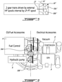
- the AGB 50" is a dual gear train comprising first and second gear trains 50a" and 50b".
- the first gear train 50a" is drivingly connected to the HP spool 40.
- the second gear train 50b" is drivingly connected to the LP spool 20 via the LP shaft 23.
- a tower shaft and an AGB input shaft arrangement similar to the one shown in Fig. 1 can be used to drivingly connect the first gear train 50a" to the HP spool 40, while the LP shaft 23 provides a second drive input along the engine centerline 17 to the second gear train of the AGB 50".
- both the drive input from the HP and LP spools could be done internally from the annular air path defined by the air inlet case 11. According to this arrangement both drive inputs to the AGB 50" are parallel to the engine centerline 17.
- first and second gear trains 50a" and 50b" can be respectively drivingly connected to first and second groups of accessories A.
- the first gear train 50a", which is driven by the HP spool 40 may be drivingly connected to the main accessories, such as the starter, the fuel control unit, and the oil pump.
- the second gear train 50b", which is driven by the LP spool 20 may be drivingly connected to secondary accessories, such as a hydraulic oil pump and an electric generator.
- the first and second gear trains 50a", 50b" are provided with an output connection for the associated accessories.
- the input axes of the accessories A are perpendicular to the output axes of the AGB 50". It is however understood that the accessories could be otherwise transversally oriented relative to the engine axis 15 (i.e. they are not limited to be at 90 degrees to the engine axis, other angles being contemplated as well). Also, the accessories could extend at various angle to the vertical axis illustrated in Fig. 6 and are thus not limited to the illustrated exemplary perpendicular orientation. The accessories could be "clocked" around the engine envelope.
Claims (15)
- Gasturbinentriebwerk (10), umfassend: ein Lufteinlassgehäuse (11) zum Aufnehmen von Luft, einen Verdichter (12), eine Brennkammer (13), eine Turbine (14), die eine Welle (43) aufweist, die um eine Turbinenwellenmittellinie (17) drehbar ist, ein Hilfsgerätegetriebe (accessory gear box - AGB) (50, 50"), deas angrenzend an ein axiales Ende des Lufteinlassgehäuses angeordnet ist und von der Turbine angetrieben wird, und mindestens ein Triebwerkshilfsgerät (A), das antriebsmäßig mit dem AGB verbunden ist und eine Eingangswelle aufweist, die eine Eingangsachse (AA) aufweist, die quer zur Turbinenwelle angeordnet ist, wobeidas AGB (50) relativ zur Turbinenwellenmittellinie (17) zentriert ist, und dadurch gekennzeichnet, dasssich das mindestens eine Triebwerkshilfsgerät seitlich von dem AGB auf einer Seite der Triebwerksmittelebene erstreckt.
- Gasturbinentriebwerk nach Anspruch 1, wobei die Eingangsachse des mindestens einen Triebwerkshilfsgeräts senkrecht zur Triebwerksmittellinie (17) ist.
- Gasturbinentriebwerk nach Anspruch 1 oder 2, wobei das AGB eine Eingangsachse aufweist, die parallel zur Turbinenwellenmittellinie ist, und wobei die Eingangsachse des AGB optional koaxial zur Turbinenwellenmittellinie ist.
- Gasturbinentriebwerk nach Anspruch 1, 2 oder 3, wobei das AGB eine Antriebseingangswelle (43') aufweist, die sich mittig durch das Lufteinlassgehäuse erstreckt, und wobei die Antriebseingangswelle des AGB optional antriebsmäßig mit einer Hochdruckspule (40) verbunden ist.
- Gasturbinentriebwerk nach einem der Ansprüche 1 bis 4, wobei das Gasturbinentriebwerk eine Niederdruck(low pressure - LP)-Spule (20) und eine Hochdruck(high pressure - HP)-Spule (40) aufweist, und wobei die LP- und die HP-Spule beide antriebsmäßig mit dem AGB (50, 50") verbunden sind.
- Gasturbinentriebwerk nach Anspruch 5, wobei das AGB einen ersten und einen zweiten Zahnradsatz (50a", 50b") umfasst, wobei der erste Zahnradsatz (50a") antriebsmäßig mit der HP-Spule verbunden ist, der zweite Zahnradsatz (50b") antriebsmäßig mit der LP-Spule verbunden ist, und wobei das mindestens eine Hilfsgerät eine erste Gruppe von Hilfsgeräten und eine zweite Gruppe von Hilfsgeräten umfasst, wobei die erste und die zweite Gruppe von Hilfsgeräten antriebsmäßig mit dem ersten beziehungsweise mit dem zweiten Zahnradsatz des AGB verbunden sind.
- Gasturbinentriebwerk nach Anspruch 6, wobei der erste Zahnradsatz eine erste Eingangswelle aufweist, der zweite Zahnradsatz eine zweite Eingangswelle aufweist, wobei die erste und die zweite Eingangswelle parallel zur Turbinenwellenmittellinie sind und sich innen durch eine Mittelbohrung des Lufteinlassgehäuses erstrecken.
- Gasturbinentriebwerk nach Anspruch 6, wobei der erste Zahnradsatz eine erste Eingangswelle aufweist, der zweite Zahnradsatz eine zweite Eingangswelle aufweist, wobei die erste Eingangswelle antriebsmäßig mit der HP-Spule über eine Turmwelle (51) verbunden ist, wobei die zweite Eingangswelle mit der LP-Spule mittig durch das Lufteinlassgehäuse verbunden ist.
- Gasturbinentriebwerk nach Anspruch 6, wobei die erste Gruppe von Hilfsgeräten mindestens eines der Folgenden umfasst: einen Anlasser, einen Kraftstoffregler und eine Ölpumpe; und wobei die zweite Gruppe von Hilfsgeräten mindestens eines der Folgenden umfasst: eine Luftvakuumpumpe und einen elektrischen Generator.
- Gasturbinentriebwerk nach Anspruch 1, wobei der Verdichter (12) um die Triebwerksmittellinie (17) drehbar ist, um die Luft aus dem Lufteinlassgehäuse mit Druck zu beaufschlagen, wobei die Luft, die durch den Verdichter verdichtet wird, im Betrieb mit Kraftstoff gemischt wird und entzündet wird, um einen Verbrennungsgasstrom in der Brennkammer (13) zu erzeugen, wobei die Turbine (14) um die Triebwerksmittellinie drehbar ist, um den Verbrennungsgasen Energie zu entziehen, wobei das Hilfsgerätegetriebe (AGB) (50, 50") relativ zur Triebwerksmittellinie stromaufwärts des Lufteinlassgehäuses zentriert ist, und das mindestens eine Triebwerkshilfsgerät Hilfsgeräte (A) umfasst, wobei die Hilfsgeräte optional jeweilige Eingangsachsen senkrecht zur Triebwerksmittellinie aufweisen.
- Gasturbinentriebwerk nach Anspruch 10, wobei das AGB an einer axial gerichteten Fläche des Lufteinlassgehäuses montiert ist.
- Gasturbinentriebwerk nach Anspruch 10 oder 11, wobei die Hilfsgeräte Öl-/Kraftstoffhilfsgeräte und elektrische Hilfsgeräte umfassen, wobei die Öl-/Kraftstoffhilfsgeräte auf einer ersten Seite einer Mittelebene des Triebwerks gruppiert sind, wobei die elektrischen Hilfsgeräte auf einer zweiten Seite der Mittelebene des Triebwerks gruppiert sind.
- Gasturbinentriebwerk (10) nach Anspruch 1, wobei der Verdichter (12) um eine Triebwerksmittellinie drehbar ist, um die Luft aus dem Lufteinlassgehäuse mit Druck zu beaufschlagen, wobei die Luft, die durch den Verdichter verdichtet wird, im Betrieb mit Kraftstoff gemischt wird und entzündet wird, um einen Verbrennungsgasstrom in der Brennkammer (13) zu erzeugen, wobei die Turbine (14) um die Triebwerksmittellinie (17) drehbar ist, um den Verbrennungsgasen Energie zu entziehen, wobei das Hilfsgerätegetriebe (AGB) (50, 50") in Reihe mit der Triebwerksmittellinie montiert ist.
- Gasturbinentriebwerk nach Anspruch 13, wobei das AGB eine Eingangsachse aufweist, die koaxial zur Triebwerksmittellinie ist.
- Gasturbinentriebwerk nach Anspruch 13 oder 14, wobei das mindestens eine Hilfsgerät eine Eingangsachse aufweist, die senkrecht zu einer zugehörigen Ausgangsachse des AGB ist.
Applications Claiming Priority (1)
| Application Number | Priority Date | Filing Date | Title |
|---|---|---|---|
| US15/351,803 US10815899B2 (en) | 2016-11-15 | 2016-11-15 | Gas turbine engine accessories arrangement |
Publications (2)
| Publication Number | Publication Date |
|---|---|
| EP3321488A1 EP3321488A1 (de) | 2018-05-16 |
| EP3321488B1 true EP3321488B1 (de) | 2022-03-02 |
Family
ID=60019699
Family Applications (1)
| Application Number | Title | Priority Date | Filing Date |
|---|---|---|---|
| EP17193893.9A Active EP3321488B1 (de) | 2016-11-15 | 2017-09-28 | Zubehöranordnung für gasturbinenmotor |
Country Status (4)
| Country | Link |
|---|---|
| US (1) | US10815899B2 (de) |
| EP (1) | EP3321488B1 (de) |
| CA (1) | CA2975556A1 (de) |
| PL (1) | PL3321488T3 (de) |
Families Citing this family (16)
| Publication number | Priority date | Publication date | Assignee | Title |
|---|---|---|---|---|
| GB2551552B (en) * | 2016-06-22 | 2018-10-03 | Rolls Royce Plc | An aircraft gas turbine engine comprising non-coaxial propulsors driven by an engine core comprising two axially spaced core modules |
| US10883424B2 (en) | 2016-07-19 | 2021-01-05 | Pratt & Whitney Canada Corp. | Multi-spool gas turbine engine architecture |
| US11415063B2 (en) | 2016-09-15 | 2022-08-16 | Pratt & Whitney Canada Corp. | Reverse-flow gas turbine engine |
| US11035293B2 (en) | 2016-09-15 | 2021-06-15 | Pratt & Whitney Canada Corp. | Reverse flow gas turbine engine with offset RGB |
| US10465611B2 (en) | 2016-09-15 | 2019-11-05 | Pratt & Whitney Canada Corp. | Reverse flow multi-spool gas turbine engine with aft-end accessory gearbox drivingly connected to both high pressure spool and low pressure spool |
| US10815899B2 (en) | 2016-11-15 | 2020-10-27 | Pratt & Whitney Canada Corp. | Gas turbine engine accessories arrangement |
| US10808624B2 (en) | 2017-02-09 | 2020-10-20 | Pratt & Whitney Canada Corp. | Turbine rotor with low over-speed requirements |
| US10746188B2 (en) | 2017-03-14 | 2020-08-18 | Pratt & Whitney Canada Corp. | Inter-shaft bearing connected to a compressor boost system |
| US10731566B2 (en) * | 2017-10-18 | 2020-08-04 | Honeywell International Inc. | Compact accessory systems for a gas turbine engine |
| EP4339440A2 (de) | 2018-08-08 | 2024-03-20 | Pratt & Whitney Canada Corp. | Mehrmotorsystem und verfahren |
| US10995675B2 (en) | 2019-02-19 | 2021-05-04 | Pratt & Whitney Canada Corp. | Gas turbine engine with accessory gearbox |
| US11408340B2 (en) | 2020-05-15 | 2022-08-09 | Pratt & Whitney Canada Corp. | Twin-engine system with electric drive |
| US11624319B2 (en) | 2020-05-15 | 2023-04-11 | Pratt & Whitney Canada Corp. | Reverse-flow gas turbine engine with electric motor |
| US11384693B2 (en) | 2020-05-15 | 2022-07-12 | Pratt & Whitney Canada Corp. | Through-flow gas turbine engine with electric motor and electric generator |
| FR3115812B1 (fr) * | 2020-10-29 | 2023-09-08 | Safran Helicopter Engines | Turbogénérateur à turbine libre comprenant une machine électrique réversible couplée à la turbine libre |
| FR3115813B1 (fr) * | 2020-10-29 | 2022-11-11 | Safran Helicopter Engines | Turbomachine à turbine libre comprenant des équipements entrainés par la turbine libre |
Family Cites Families (176)
| Publication number | Priority date | Publication date | Assignee | Title |
|---|---|---|---|---|
| NL69078C (de) | 1944-01-31 | |||
| FR991975A (fr) | 1948-08-06 | 1951-10-12 | Garrett Corp | Groupe moteur |
| US2747367A (en) | 1950-03-21 | 1956-05-29 | United Aircraft Corp | Gas turbine power plant supporting structure |
| GB713839A (en) | 1951-07-25 | 1954-08-18 | Albert Enticknap | Improvements in or relating to internal combustion turbines |
| GB817591A (en) | 1954-11-08 | 1959-08-06 | Parsons C A & Co Ltd | Improvements in and relating to gas turbine plants |
| US2929207A (en) | 1955-08-08 | 1960-03-22 | Adolphe C Peterson | Axial flow gas turbine |
| US3152443A (en) * | 1959-07-17 | 1964-10-13 | United Aircraft Canada | Gas turbine powerplant |
| US3170292A (en) | 1960-04-04 | 1965-02-23 | Ford Motor Co | Lubricating system for a gas turbine engine |
| US3209536A (en) | 1960-04-04 | 1965-10-05 | Ford Motor Co | Re-expansion type gas turbine engine with intercooler fan driven by the low pressure turbine |
| US3204406A (en) | 1960-04-04 | 1965-09-07 | Ford Motor Co | Cooling system for a re-expansion gas turbine engine |
| US2984977A (en) | 1961-05-23 | 1961-05-23 | United Aircraft Corp | Pneumatic control of fuel for a twin spool jet engine |
| FR1325704A (fr) | 1962-03-14 | 1963-05-03 | Sud Aviation | Perfectionnement apporté aux boîtes de transmission pour hélicoptères monorotor à plusieurs turbines |
| GB1102591A (en) | 1964-05-22 | 1968-02-07 | Auto Transmissions Ltd | Power transmission system for a gas turbine engine |
| US3488947A (en) | 1967-11-24 | 1970-01-13 | Boeing Co | Torque transfer apparatus for a free shaft gas turbine engine |
| US3529419A (en) * | 1968-07-23 | 1970-09-22 | Int Harvester Co | Gas turbine engine and control system |
| FR1594317A (de) | 1968-11-29 | 1970-06-01 | ||
| DE2006138A1 (de) | 1970-02-11 | 1971-08-19 | Daimler Benz Ag | Gasturbine zum Antrieb von Kraftfahr |
| US4055949A (en) | 1973-05-08 | 1977-11-01 | Societe Nationale D'etude Et De Construction De Moteurs D'aviation | Multiflow gas turbine power plant |
| US3874811A (en) | 1974-04-19 | 1975-04-01 | United Aircraft Corp | Hi and low turbine bearing support system |
| US4141212A (en) | 1977-06-20 | 1979-02-27 | Avco Corporation | Differentially geared regenerative reverse flow turbo shaft engine |
| US4251987A (en) | 1979-08-22 | 1981-02-24 | General Electric Company | Differential geared engine |
| EP0103370A1 (de) | 1982-08-11 | 1984-03-21 | Rolls-Royce Plc | Gasturbinenmotoren |
| US4498291A (en) | 1982-10-06 | 1985-02-12 | Rolls-Royce Limited | Turbine overspeed limiter for turbomachines |
| US4531694A (en) | 1982-10-18 | 1985-07-30 | Soloy Conversions, Ltd. | Turbine engine drive and mounting assembly for fixed wing aircraft |
| US4685286A (en) | 1984-05-02 | 1987-08-11 | United Technologies Corporation | Method of disassembly for a gas turbine engine |
| US4611464A (en) | 1984-05-02 | 1986-09-16 | United Technologies Corporation | Rotor assembly for a gas turbine engine and method of disassembly |
| US4817382A (en) | 1985-12-31 | 1989-04-04 | The Boeing Company | Turboprop propulsion apparatus |
| US4864812A (en) * | 1987-11-13 | 1989-09-12 | Sundstrand Corporation | Combined auxiliary and emergency power unit |
| US5309708A (en) * | 1988-06-03 | 1994-05-10 | Alliedsignal Inc. | Multifunction integrated power unit |
| US5159808A (en) * | 1990-07-09 | 1992-11-03 | General Electric Company | Gas turbine engine fuel and hydraulic fluid pumping system |
| US5161364A (en) | 1991-04-01 | 1992-11-10 | United Technologies Corporation | Control of aircraft bleed air stage mixing |
| GB9313905D0 (en) | 1993-07-06 | 1993-08-25 | Rolls Royce Plc | Shaft power transfer in gas turbine engines |
| FR2759734B1 (fr) | 1997-02-20 | 1999-04-09 | Snecma | Turbomachine a systeme de compression optimise |
| FR2761412B1 (fr) | 1997-03-27 | 1999-04-30 | Snecma | Groupe turbopropulseur double corps a regulation isodrome |
| US6041589A (en) | 1998-01-09 | 2000-03-28 | General Electric Company | Asymmetric turboprop booster |
| US6247668B1 (en) | 1999-07-15 | 2001-06-19 | The Boeing Company | Auxiliary power and thrust unit |
| US6663530B2 (en) * | 2001-12-14 | 2003-12-16 | Pratt & Whitney Canada Corp. | Zero twist carrier |
| DE60313392T2 (de) | 2002-05-16 | 2007-08-09 | Rolls-Royce Plc | Gasturbine |
| EP1601864B1 (de) | 2003-02-24 | 2010-07-07 | Pratt & Whitney Canada Corp. | Eingebautes kühlsystem für einen umlaufmotor |
| US6895741B2 (en) | 2003-06-23 | 2005-05-24 | Pratt & Whitney Canada Corp. | Differential geared turbine engine with torque modulation capability |
| FR2858999B1 (fr) | 2003-08-18 | 2005-11-11 | Snecma Moteurs | Turbomachine pour aeronef a emissions de bruit reduites |
| FR2863312B1 (fr) | 2003-12-09 | 2008-07-04 | Snecma Moteurs | Turboreacteur a double corps avec moyen d'entrainement des machines accessoires |
| US7055303B2 (en) | 2003-12-22 | 2006-06-06 | Pratt & Whitney Canada Corp. | Gas turbine engine architecture |
| US7144349B2 (en) | 2004-04-06 | 2006-12-05 | Pratt & Whitney Canada Corp. | Gas turbine gearbox |
| US20060010152A1 (en) | 2004-07-12 | 2006-01-12 | Snecma Services | System and method for managing machine servicing including workscope generation |
| US7762084B2 (en) | 2004-11-12 | 2010-07-27 | Rolls-Royce Canada, Ltd. | System and method for controlling the working line position in a gas turbine engine compressor |
| US20060137355A1 (en) | 2004-12-27 | 2006-06-29 | Pratt & Whitney Canada Corp. | Fan driven emergency generator |
| FR2882096B1 (fr) | 2005-02-11 | 2012-04-20 | Snecma Moteurs | Turbomoteur a double corps avec des moyens de prise de mouvement sur les rotors basse pression et haute pression, module de prise de mouvement pour le turbomoteur et procede de montage du turbomoteur |
| US7500365B2 (en) | 2005-05-05 | 2009-03-10 | United Technologies Corporation | Accessory gearbox |
| US8220245B1 (en) | 2005-08-03 | 2012-07-17 | Candent Technologies, Inc. | Multi spool gas turbine system |
| FR2892456B1 (fr) * | 2005-10-21 | 2008-01-04 | Hispano Suiza Sa | Dispositif d'entrainement de machines accessoires d'un moteur a turbine a gaz |
| FR2894621B1 (fr) | 2005-12-09 | 2011-10-14 | Hispano Suiza Sa | Systeme d'entrainement de machines auxiliaires d'un turbomoteur a double corps |
| US7691028B2 (en) | 2006-05-02 | 2010-04-06 | Conocophillips Company | Mechanical soft-start system for rotating industrial equipment |
| EP2066896B1 (de) | 2006-08-22 | 2016-10-05 | Rolls-Royce North American Technologies, Inc. | Gasturbinenmotor mit zwischengeschwindigkeitsverstärker |
| US20080075590A1 (en) | 2006-09-27 | 2008-03-27 | Thomas Ory Moniz | Gas turbine engine assembly and method of assembling same |
| EP2074288B1 (de) | 2006-10-12 | 2014-06-25 | United Technologies Corporation | Mantelstromtriebwerk mit gebläsedüse mit variablem querschnitt und niedrigwellengenerator zur notstromerzeugung und verfahren zur notstromversorgung |
| US8302405B2 (en) | 2006-10-13 | 2012-11-06 | Rolls-Royce Power Engineering Plc | Dynamic control of a gas turbine engine compressor during rapid transients |
| US7788898B2 (en) | 2006-12-06 | 2010-09-07 | General Electric Company | Variable coupling of turbofan engine spools via open differential gear set or simple planetary gear set for improved power extraction and engine operability, with torque coupling for added flexibility |
| US20080148881A1 (en) | 2006-12-21 | 2008-06-26 | Thomas Ory Moniz | Power take-off system and gas turbine engine assembly including same |
| US7942079B2 (en) | 2007-02-16 | 2011-05-17 | Hamilton Sundstrand Corporation | Multi-speed gearbox for low spool driven auxiliary component |
| FR2915523A1 (fr) | 2007-04-27 | 2008-10-31 | Snecma Sa | Dispositif de production d'energie electrique dans un moteur a turbine a gaz a double corps |
| US9126691B2 (en) | 2007-05-30 | 2015-09-08 | United Technologies Corporation | Access door for gas turbine engine components |
| US8104289B2 (en) | 2007-10-09 | 2012-01-31 | United Technologies Corp. | Systems and methods involving multiple torque paths for gas turbine engines |
| US20090188334A1 (en) | 2008-01-25 | 2009-07-30 | United Technologies Corp. | Accessory Gearboxes and Related Gas Turbine Engine Systems |
| US8169100B2 (en) | 2008-01-30 | 2012-05-01 | Pratt & Whitney Canada Corp. | Torque transmission for an aircraft engine |
| US8146370B2 (en) | 2008-05-21 | 2012-04-03 | Honeywell International Inc. | Turbine drive system with lock-up clutch and method |
| US20100162720A1 (en) | 2008-12-31 | 2010-07-01 | Bowman Ray F | Gas turbine engine |
| US20100180568A1 (en) | 2009-01-22 | 2010-07-22 | Sachs Humberto W | Heat regeneration for a turbofan, a Velarus Propulsion |
| FR2941744B1 (fr) | 2009-01-30 | 2011-09-16 | Hispano Suiza Sa | Ensemble d'un boitier de relais d'accessoires et d'un reservoir d'huile |
| DE102009010524A1 (de) | 2009-02-25 | 2010-09-02 | Rolls-Royce Deutschland Ltd & Co Kg | Turbopropantrieb mit Druckpropeller |
| GB0903423D0 (en) | 2009-03-02 | 2009-04-08 | Rolls Royce Plc | Variable drive gas turbine engine |
| US8176725B2 (en) | 2009-09-09 | 2012-05-15 | United Technologies Corporation | Reversed-flow core for a turbofan with a fan drive gear system |
| JP5016706B2 (ja) | 2009-11-04 | 2012-09-05 | 川崎重工業株式会社 | 航空機用始動発電装置 |
| GB2476261A (en) | 2009-12-17 | 2011-06-22 | Richard Julius Gozdawa | A gas turbine generator |
| GB201000198D0 (en) | 2010-01-08 | 2010-02-24 | Rolls Royce Plc | Back-up featherer |
| US9512784B2 (en) | 2010-01-29 | 2016-12-06 | Pratt & Whitney Canada Corp. | Free gas turbine with constant temperature-corrected gas generator speed |
| US8568089B2 (en) | 2010-06-03 | 2013-10-29 | Hamilton Sundstrand Corporation | Gear arrangement |
| FR2963062B1 (fr) | 2010-07-20 | 2012-08-31 | Snecma | Assemblage entre un tourillon d'arbre de compresseur et un pignon conique pour l'entrainement d'un boitier d'accessoires d'une turbomachine |
| US8490411B2 (en) * | 2010-11-17 | 2013-07-23 | United Technologies Corporation | Axial accessory gearbox |
| DE102011009770B4 (de) | 2011-01-28 | 2017-06-29 | Lufthansa Technik Ag | Verfahren und Vorrichtung zum Wechseln einer Dichtungsplatte und/oder einer Lagereinheit in einem Flugzeugtriebwerk |
| US9926849B2 (en) * | 2011-06-14 | 2018-03-27 | Honeywell International Inc. | Transverse mounted accessory gearbox |
| US9145834B2 (en) | 2011-06-14 | 2015-09-29 | Honeywell International Inc. | Transverse mounted accessory gearbox |
| US8516789B2 (en) | 2011-07-26 | 2013-08-27 | United Technologies Corporation | Gas turbine engine with aft core driven fan section |
| US20130031912A1 (en) | 2011-08-01 | 2013-02-07 | Hamilton Sundstrand Corporation | Gas turbine start architecture |
| US9062611B2 (en) | 2011-10-19 | 2015-06-23 | United Technologies Corporation | Split accessory drive system |
| FR2981686B1 (fr) | 2011-10-21 | 2016-05-20 | Snecma | Turbomachine comprenant un recepteur a helices contrarotatives supporte par une enveloppe structurale fixee au carter intermediaire |
| US9091216B2 (en) | 2011-11-29 | 2015-07-28 | Pratt & Whitney Canada Corp. | Systems and methods for changing a speed of a compressor boost stage in a gas turbine |
| US9429077B2 (en) | 2011-12-06 | 2016-08-30 | Pratt & Whitney Canada Corp. | Multiple turboshaft engine control method and system for helicopters |
| US8935912B2 (en) | 2011-12-09 | 2015-01-20 | United Technologies Corporation | Gas turbine engine with variable overall pressure ratio |
| US20130186058A1 (en) | 2012-01-24 | 2013-07-25 | William G. Sheridan | Geared turbomachine fan and compressor rotation |
| US9097186B2 (en) * | 2012-01-29 | 2015-08-04 | United Technologies Corporation | Bevel gear arrangement for axial accessory gearbox |
| US8459038B1 (en) | 2012-02-09 | 2013-06-11 | Williams International Co., L.L.C. | Two-spool turboshaft engine control system and method |
| US9239004B2 (en) | 2012-03-27 | 2016-01-19 | United Technologies Corporation | Reverse core gear turbofan |
| US9382010B2 (en) | 2012-07-12 | 2016-07-05 | Pratt & Whitney Canada Corp. | Aircraft power outtake management |
| US9410441B2 (en) | 2012-09-13 | 2016-08-09 | Pratt & Whitney Canada Corp. | Turboprop engine with compressor turbine shroud |
| US20150150401A1 (en) | 2012-09-26 | 2015-06-04 | Daniel Paul Bennett | Carpet seam tape |
| GB201219544D0 (en) | 2012-10-31 | 2012-12-12 | Rolls Royce Deutschland | Geared compressor for gas turbine engine |
| US10329956B2 (en) | 2012-12-29 | 2019-06-25 | United Technologies Corporation | Multi-function boss for a turbine exhaust case |
| EP2943667B1 (de) | 2013-01-10 | 2019-07-24 | United Technologies Corporation | Zweispulengasgenerator mit verbesserter luftportierung |
| US10072570B2 (en) | 2013-01-28 | 2018-09-11 | United Technologies Corporation | Reverse flow gas turbine engine core |
| WO2014120115A1 (en) | 2013-01-29 | 2014-08-07 | United Technologies Corporation | Reverse-flow core gas turbine engine with a pulse detonation system |
| US10094295B2 (en) | 2013-01-30 | 2018-10-09 | Pratt & Whitney Canada Corp. | Gas turbine engine with transmission |
| US9726112B2 (en) | 2013-03-07 | 2017-08-08 | United Technologies Corporation | Reverse flow gas turbine engine airflow bypass |
| US20140252160A1 (en) | 2013-03-07 | 2014-09-11 | United Technologies Corporation | Reverse flow gas turbine engine removable core |
| AU2014226413B2 (en) | 2013-03-08 | 2016-04-28 | Exxonmobil Upstream Research Company | Power generation and methane recovery from methane hydrates |
| US9234441B2 (en) | 2013-03-11 | 2016-01-12 | Pratt & Whitney Canada Corp. | Method of immobilizing low pressure spool and locking tool therefore |
| US8870699B2 (en) | 2013-03-11 | 2014-10-28 | Pratt & Whitney Canada Corp. | Lubrication oil system for a reduction gearbox |
| US9322341B2 (en) | 2013-03-12 | 2016-04-26 | Pratt & Whitney Canada Corp. | System and method for engine transient power response |
| US9353848B2 (en) | 2013-03-13 | 2016-05-31 | Hamilton Sundstrand Corporation | Spline lubrication system |
| US9752500B2 (en) | 2013-03-14 | 2017-09-05 | Pratt & Whitney Canada Corp. | Gas turbine engine with transmission and method of adjusting rotational speed |
| FR3003323B1 (fr) | 2013-03-14 | 2016-10-07 | Snecma | Fixation d'une boite d'engrenages en v sur une turbomachine |
| WO2014193515A2 (en) | 2013-03-14 | 2014-12-04 | United Technologies Corporation | Reverse core engine with thrust reverser |
| WO2014176180A1 (en) | 2013-04-22 | 2014-10-30 | United Technologies Corporation | Low loss bearing drain |
| GB2513621B (en) | 2013-05-01 | 2015-09-23 | Trevor Harold Speak | Compressor system |
| US8853878B1 (en) | 2013-05-14 | 2014-10-07 | Solar Turbines Inc. | Gas turbine engine with multiple load outputs |
| US9970386B2 (en) | 2013-06-07 | 2018-05-15 | United Technologies Corporation | Exhaust stream mixer |
| DE102013213518A1 (de) | 2013-07-10 | 2015-01-15 | Rolls-Royce Deutschland Ltd & Co Kg | Turbofan-Triebwerk |
| US20160069264A1 (en) | 2013-07-22 | 2016-03-10 | Joseph D. Brostmeyer | Gas turbine engine with turbine cooling and combustor air preheating |
| IL228274A (en) | 2013-09-03 | 2016-10-31 | Israel Aerospace Ind Ltd | Fan Turbo Engine and Method of Removing Fan Fan Turbo |
| WO2015122948A2 (en) | 2013-12-05 | 2015-08-20 | United Technologies Corporation | Gas turbine engines with intercoolers and recuperators |
| WO2015088606A2 (en) | 2013-12-13 | 2015-06-18 | United Technologies Corporation | Architecture for an axially compact, high performance propulsion system |
| US9341121B2 (en) | 2013-12-13 | 2016-05-17 | United Technologies Corporation | Gas turbine engine with intercooling turbine section and intercooling turbine section bypass |
| EP3114327B1 (de) | 2014-03-06 | 2020-01-08 | United Technologies Corporation | Aufbaue eines zusatzaggregats für einen gasturbinenmotor |
| FR3022301B1 (fr) | 2014-06-12 | 2016-07-29 | Snecma | Turbomachine comprenant un systeme d'entrainement d'un equipement tel qu'un boitier d'accessoires |
| US10094277B2 (en) | 2014-06-20 | 2018-10-09 | United Technologies Corporation | Gas turbine engine configured for modular assembly/disassembly and method for same |
| US20160169118A1 (en) | 2014-12-12 | 2016-06-16 | United Technologies Corporation | Dual tower shaft gearbox for gas turbine engine |
| PL3550133T3 (pl) | 2014-12-17 | 2022-08-01 | Pratt & Whitney Canada Corp. | Przewód wydechowy do silnika turbogazowego |
| US20160178464A1 (en) * | 2014-12-19 | 2016-06-23 | Rolls-Royce Corporation | Torque sensor monitoring for gas turbine engine |
| JP6511265B2 (ja) | 2014-12-24 | 2019-05-15 | 川崎重工業株式会社 | 航空機用エンジン装置 |
| US9819292B2 (en) | 2014-12-31 | 2017-11-14 | General Electric Company | Systems and methods to respond to grid overfrequency events for a stoichiometric exhaust recirculation gas turbine |
| US10072571B2 (en) | 2015-01-15 | 2018-09-11 | United Technologies Corporation | Gas turbine engine split torque fan drive gear system |
| US20160230843A1 (en) | 2015-02-09 | 2016-08-11 | United Technologies Corporation | Gearbox for gas turbine engine |
| US10125722B2 (en) | 2015-02-13 | 2018-11-13 | United Technologies Corporation | Turbine engine with a turbo-compressor |
| US10371060B2 (en) | 2015-02-20 | 2019-08-06 | Pratt & Whitney Canada Corp. | Compound engine assembly with confined fire zone |
| US20160305261A1 (en) | 2015-04-16 | 2016-10-20 | John A Orosa | High pressure ratio twin spool industrial gas turbine engine with dual flow high spool compressor |
| EP3093440A1 (de) | 2015-05-01 | 2016-11-16 | Rolls-Royce North American Technologies, Inc. | Gebläseschaufelschwingungsüberwachungs- und -steuerungssystem und -verfahren |
| GB201508550D0 (en) | 2015-05-19 | 2015-07-01 | Rolls Royce Plc | Improved alignment of flanged components |
| FR3039133B1 (fr) | 2015-07-22 | 2020-01-17 | Safran Aircraft Engines | Aeronef avec un ensemble propulsif comprenant une soufflante a l'arriere du fuselage |
| US9932858B2 (en) | 2015-07-27 | 2018-04-03 | General Electric Company | Gas turbine engine frame assembly |
| EP3135882B1 (de) | 2015-08-26 | 2020-04-15 | Honeywell International Inc. | Quermontierter hilfsgeräteantrieb |
| GB201518227D0 (en) | 2015-10-15 | 2015-12-02 | Rolls Royce Plc | A geared gas turbine engine |
| GB201600180D0 (en) | 2016-01-06 | 2016-02-17 | Rolls Royce Plc | Gas turbine engine |
| US10590854B2 (en) | 2016-01-26 | 2020-03-17 | United Technologies Corporation | Geared gas turbine engine |
| US10329955B2 (en) | 2016-01-27 | 2019-06-25 | Pratt & Whitney Canada Corp. | Oil system for turbine engine and related method |
| US10378438B2 (en) | 2016-04-20 | 2019-08-13 | Rolls-Royce North American Technologies, Inc. | Reverse flow gas turbine engine with radially outward turbine |
| US10577118B2 (en) | 2016-04-27 | 2020-03-03 | Pratt & Whitney Canada Corp. | Power plant management system for dual engine helicopter in single engine operation mode |
| US10072582B2 (en) * | 2016-04-28 | 2018-09-11 | General Electric Company | Integral offset oil tank for inline accessory gearbox |
| US10619567B2 (en) | 2016-04-29 | 2020-04-14 | Rolls-Royce Corporation | Reconfigurable lubrication system for multiple powertrain orientations |
| GB2550397B (en) | 2016-05-19 | 2018-11-21 | Derwent Aviation Consulting Ltd | A turbo machine comprising a compressor system |
| GB201610234D0 (en) | 2016-06-13 | 2016-07-27 | Rolls Royce Plc | An accessory gearbox assembly and a gas turbine engine comprising an accessory gearbox assembly |
| US10316855B2 (en) | 2016-06-13 | 2019-06-11 | United Technologies Corporation | Shaft anti-rotation device |
| GB2551551B (en) | 2016-06-22 | 2018-09-05 | Rolls Royce Plc | Gas Turbine Engine |
| US10823061B2 (en) * | 2016-07-15 | 2020-11-03 | General Electric Company | Engine air inlet having a double-panel heated wall |
| EP3597884B1 (de) | 2016-07-19 | 2022-04-20 | Pratt & Whitney Canada Corp. | Architektur eines mehrspuligen gasturbinentriebwerks |
| CA2970386A1 (en) | 2016-07-19 | 2018-01-19 | Pratt & Whitney Canada Corp. | A multi-spool gas turbine engine architecture |
| US10883424B2 (en) | 2016-07-19 | 2021-01-05 | Pratt & Whitney Canada Corp. | Multi-spool gas turbine engine architecture |
| US11415063B2 (en) | 2016-09-15 | 2022-08-16 | Pratt & Whitney Canada Corp. | Reverse-flow gas turbine engine |
| US11203949B2 (en) | 2016-08-11 | 2021-12-21 | General Electric Company | Mechanically driven air vehicle thermal management device |
| US11022042B2 (en) | 2016-08-29 | 2021-06-01 | Rolls-Royce North American Technologies Inc. | Aircraft having a gas turbine generator with power assist |
| US11035293B2 (en) | 2016-09-15 | 2021-06-15 | Pratt & Whitney Canada Corp. | Reverse flow gas turbine engine with offset RGB |
| US10465611B2 (en) | 2016-09-15 | 2019-11-05 | Pratt & Whitney Canada Corp. | Reverse flow multi-spool gas turbine engine with aft-end accessory gearbox drivingly connected to both high pressure spool and low pressure spool |
| US9745860B1 (en) | 2016-11-02 | 2017-08-29 | Jay HASKIN | Power transmission system for turbine or compressor having counter-rotating blades |
| US10815899B2 (en) | 2016-11-15 | 2020-10-27 | Pratt & Whitney Canada Corp. | Gas turbine engine accessories arrangement |
| US10526975B2 (en) | 2016-11-30 | 2020-01-07 | The Boeing Company | Power extraction system and method for a gas turbine engine of a vehicle |
| US10436060B2 (en) | 2016-12-09 | 2019-10-08 | Pratt & Whitney Canada Corp. | Shaft event detection in gas turbine engines |
| US20180171815A1 (en) | 2016-12-16 | 2018-06-21 | United Technologies Corporation | Traction drive transmission for gas turbine engine accessory gearbox |
| US10533559B2 (en) | 2016-12-20 | 2020-01-14 | Pratt & Whitney Canada Corp. | Reverse flow engine architecture |
| US10995673B2 (en) | 2017-01-19 | 2021-05-04 | Raytheon Technologies Corporation | Gas turbine engine with intercooled cooling air and dual towershaft accessory gearbox |
| US10422243B2 (en) | 2017-01-19 | 2019-09-24 | United Technologies Corporation | Gas turbine engine dual towershaft accessory gearbox and starter generator assembly |
| US20180216525A1 (en) | 2017-01-30 | 2018-08-02 | Pratt & Whitney Canada Corp. | Gas turbine engine architecture with split compressor system |
| US10808624B2 (en) | 2017-02-09 | 2020-10-20 | Pratt & Whitney Canada Corp. | Turbine rotor with low over-speed requirements |
| US20180283281A1 (en) | 2017-03-31 | 2018-10-04 | Hamilton Sundstrand Corporation | Accessory gearboxes |
| US10358981B2 (en) | 2017-04-11 | 2019-07-23 | United Technologies Corporation | High and low spool accessory gearbox drive |
| US10502142B2 (en) * | 2017-04-11 | 2019-12-10 | United Technologies Corporation | Turbine engine gearbox assembly with sets of inline gears |
| US10526976B2 (en) | 2017-04-27 | 2020-01-07 | United Technologies Corporation | Tangential drive for gas turbine engine accessories |
| US10823080B2 (en) | 2017-05-31 | 2020-11-03 | General Electric Company | Dual accessory gearbox |
-
2016
- 2016-11-15 US US15/351,803 patent/US10815899B2/en active Active
-
2017
- 2017-08-04 CA CA2975556A patent/CA2975556A1/en active Pending
- 2017-09-28 PL PL17193893.9T patent/PL3321488T3/pl unknown
- 2017-09-28 EP EP17193893.9A patent/EP3321488B1/de active Active
Also Published As
| Publication number | Publication date |
|---|---|
| CA2975556A1 (en) | 2018-05-15 |
| EP3321488A1 (de) | 2018-05-16 |
| PL3321488T3 (pl) | 2022-08-16 |
| US20180135522A1 (en) | 2018-05-17 |
| US10815899B2 (en) | 2020-10-27 |
Similar Documents
| Publication | Publication Date | Title |
|---|---|---|
| US11041443B2 (en) | Multi-spool gas turbine engine architecture | |
| EP3321488B1 (de) | Zubehöranordnung für gasturbinenmotor | |
| US11408352B2 (en) | Reverse-flow gas turbine engine | |
| US10767567B2 (en) | Multi-spool gas turbine engine architecture | |
| EP3722575B1 (de) | Gegenstrommotorarchitektur | |
| EP3296541B1 (de) | Gasturbinenmotor mit umgekehrter durchflussrichtung mit versetztem getriebe | |
| EP3354876B1 (de) | Gasturbinenmotor mit architektur mit geteiltem kompressorsystem | |
| EP3597884B1 (de) | Architektur eines mehrspuligen gasturbinentriebwerks | |
| CA2970386A1 (en) | A multi-spool gas turbine engine architecture |
Legal Events
| Date | Code | Title | Description |
|---|---|---|---|
| PUAI | Public reference made under article 153(3) epc to a published international application that has entered the european phase |
Free format text: ORIGINAL CODE: 0009012 |
|
| STAA | Information on the status of an ep patent application or granted ep patent |
Free format text: STATUS: THE APPLICATION HAS BEEN PUBLISHED |
|
| AK | Designated contracting states |
Kind code of ref document: A1 Designated state(s): AL AT BE BG CH CY CZ DE DK EE ES FI FR GB GR HR HU IE IS IT LI LT LU LV MC MK MT NL NO PL PT RO RS SE SI SK SM TR |
|
| AX | Request for extension of the european patent |
Extension state: BA ME |
|
| STAA | Information on the status of an ep patent application or granted ep patent |
Free format text: STATUS: REQUEST FOR EXAMINATION WAS MADE |
|
| 17P | Request for examination filed |
Effective date: 20181115 |
|
| RBV | Designated contracting states (corrected) |
Designated state(s): AL AT BE BG CH CY CZ DE DK EE ES FI FR GB GR HR HU IE IS IT LI LT LU LV MC MK MT NL NO PL PT RO RS SE SI SK SM TR |
|
| STAA | Information on the status of an ep patent application or granted ep patent |
Free format text: STATUS: REQUEST FOR EXAMINATION WAS MADE |
|
| GRAP | Despatch of communication of intention to grant a patent |
Free format text: ORIGINAL CODE: EPIDOSNIGR1 |
|
| STAA | Information on the status of an ep patent application or granted ep patent |
Free format text: STATUS: GRANT OF PATENT IS INTENDED |
|
| RIC1 | Information provided on ipc code assigned before grant |
Ipc: F02C 3/14 20060101AFI20210520BHEP Ipc: F02C 7/32 20060101ALI20210520BHEP |
|
| INTG | Intention to grant announced |
Effective date: 20210617 |
|
| GRAJ | Information related to disapproval of communication of intention to grant by the applicant or resumption of examination proceedings by the epo deleted |
Free format text: ORIGINAL CODE: EPIDOSDIGR1 |
|
| STAA | Information on the status of an ep patent application or granted ep patent |
Free format text: STATUS: REQUEST FOR EXAMINATION WAS MADE |
|
| INTC | Intention to grant announced (deleted) | ||
| GRAP | Despatch of communication of intention to grant a patent |
Free format text: ORIGINAL CODE: EPIDOSNIGR1 |
|
| STAA | Information on the status of an ep patent application or granted ep patent |
Free format text: STATUS: GRANT OF PATENT IS INTENDED |
|
| INTG | Intention to grant announced |
Effective date: 20211125 |
|
| GRAS | Grant fee paid |
Free format text: ORIGINAL CODE: EPIDOSNIGR3 |
|
| GRAA | (expected) grant |
Free format text: ORIGINAL CODE: 0009210 |
|
| STAA | Information on the status of an ep patent application or granted ep patent |
Free format text: STATUS: THE PATENT HAS BEEN GRANTED |
|
| AK | Designated contracting states |
Kind code of ref document: B1 Designated state(s): AL AT BE BG CH CY CZ DE DK EE ES FI FR GB GR HR HU IE IS IT LI LT LU LV MC MK MT NL NO PL PT RO RS SE SI SK SM TR |
|
| REG | Reference to a national code |
Ref country code: GB Ref legal event code: FG4D |
|
| REG | Reference to a national code |
Ref country code: CH Ref legal event code: EP Ref country code: AT Ref legal event code: REF Ref document number: 1472415 Country of ref document: AT Kind code of ref document: T Effective date: 20220315 |
|
| REG | Reference to a national code |
Ref country code: DE Ref legal event code: R096 Ref document number: 602017053951 Country of ref document: DE |
|
| REG | Reference to a national code |
Ref country code: IE Ref legal event code: FG4D |
|
| REG | Reference to a national code |
Ref country code: LT Ref legal event code: MG9D |
|
| REG | Reference to a national code |
Ref country code: NL Ref legal event code: MP Effective date: 20220302 |
|
| PG25 | Lapsed in a contracting state [announced via postgrant information from national office to epo] |
Ref country code: SE Free format text: LAPSE BECAUSE OF FAILURE TO SUBMIT A TRANSLATION OF THE DESCRIPTION OR TO PAY THE FEE WITHIN THE PRESCRIBED TIME-LIMIT Effective date: 20220302 Ref country code: RS Free format text: LAPSE BECAUSE OF FAILURE TO SUBMIT A TRANSLATION OF THE DESCRIPTION OR TO PAY THE FEE WITHIN THE PRESCRIBED TIME-LIMIT Effective date: 20220302 Ref country code: NO Free format text: LAPSE BECAUSE OF FAILURE TO SUBMIT A TRANSLATION OF THE DESCRIPTION OR TO PAY THE FEE WITHIN THE PRESCRIBED TIME-LIMIT Effective date: 20220602 Ref country code: LT Free format text: LAPSE BECAUSE OF FAILURE TO SUBMIT A TRANSLATION OF THE DESCRIPTION OR TO PAY THE FEE WITHIN THE PRESCRIBED TIME-LIMIT Effective date: 20220302 Ref country code: HR Free format text: LAPSE BECAUSE OF FAILURE TO SUBMIT A TRANSLATION OF THE DESCRIPTION OR TO PAY THE FEE WITHIN THE PRESCRIBED TIME-LIMIT Effective date: 20220302 Ref country code: ES Free format text: LAPSE BECAUSE OF FAILURE TO SUBMIT A TRANSLATION OF THE DESCRIPTION OR TO PAY THE FEE WITHIN THE PRESCRIBED TIME-LIMIT Effective date: 20220302 Ref country code: BG Free format text: LAPSE BECAUSE OF FAILURE TO SUBMIT A TRANSLATION OF THE DESCRIPTION OR TO PAY THE FEE WITHIN THE PRESCRIBED TIME-LIMIT Effective date: 20220602 |
|
| REG | Reference to a national code |
Ref country code: AT Ref legal event code: MK05 Ref document number: 1472415 Country of ref document: AT Kind code of ref document: T Effective date: 20220302 |
|
| PG25 | Lapsed in a contracting state [announced via postgrant information from national office to epo] |
Ref country code: LV Free format text: LAPSE BECAUSE OF FAILURE TO SUBMIT A TRANSLATION OF THE DESCRIPTION OR TO PAY THE FEE WITHIN THE PRESCRIBED TIME-LIMIT Effective date: 20220302 Ref country code: GR Free format text: LAPSE BECAUSE OF FAILURE TO SUBMIT A TRANSLATION OF THE DESCRIPTION OR TO PAY THE FEE WITHIN THE PRESCRIBED TIME-LIMIT Effective date: 20220603 Ref country code: FI Free format text: LAPSE BECAUSE OF FAILURE TO SUBMIT A TRANSLATION OF THE DESCRIPTION OR TO PAY THE FEE WITHIN THE PRESCRIBED TIME-LIMIT Effective date: 20220302 |
|
| PG25 | Lapsed in a contracting state [announced via postgrant information from national office to epo] |
Ref country code: NL Free format text: LAPSE BECAUSE OF FAILURE TO SUBMIT A TRANSLATION OF THE DESCRIPTION OR TO PAY THE FEE WITHIN THE PRESCRIBED TIME-LIMIT Effective date: 20220302 |
|
| PG25 | Lapsed in a contracting state [announced via postgrant information from national office to epo] |
Ref country code: SM Free format text: LAPSE BECAUSE OF FAILURE TO SUBMIT A TRANSLATION OF THE DESCRIPTION OR TO PAY THE FEE WITHIN THE PRESCRIBED TIME-LIMIT Effective date: 20220302 Ref country code: SK Free format text: LAPSE BECAUSE OF FAILURE TO SUBMIT A TRANSLATION OF THE DESCRIPTION OR TO PAY THE FEE WITHIN THE PRESCRIBED TIME-LIMIT Effective date: 20220302 Ref country code: RO Free format text: LAPSE BECAUSE OF FAILURE TO SUBMIT A TRANSLATION OF THE DESCRIPTION OR TO PAY THE FEE WITHIN THE PRESCRIBED TIME-LIMIT Effective date: 20220302 Ref country code: PT Free format text: LAPSE BECAUSE OF FAILURE TO SUBMIT A TRANSLATION OF THE DESCRIPTION OR TO PAY THE FEE WITHIN THE PRESCRIBED TIME-LIMIT Effective date: 20220704 Ref country code: EE Free format text: LAPSE BECAUSE OF FAILURE TO SUBMIT A TRANSLATION OF THE DESCRIPTION OR TO PAY THE FEE WITHIN THE PRESCRIBED TIME-LIMIT Effective date: 20220302 Ref country code: AT Free format text: LAPSE BECAUSE OF FAILURE TO SUBMIT A TRANSLATION OF THE DESCRIPTION OR TO PAY THE FEE WITHIN THE PRESCRIBED TIME-LIMIT Effective date: 20220302 |
|
| PG25 | Lapsed in a contracting state [announced via postgrant information from national office to epo] |
Ref country code: IS Free format text: LAPSE BECAUSE OF FAILURE TO SUBMIT A TRANSLATION OF THE DESCRIPTION OR TO PAY THE FEE WITHIN THE PRESCRIBED TIME-LIMIT Effective date: 20220702 Ref country code: AL Free format text: LAPSE BECAUSE OF FAILURE TO SUBMIT A TRANSLATION OF THE DESCRIPTION OR TO PAY THE FEE WITHIN THE PRESCRIBED TIME-LIMIT Effective date: 20220302 |
|
| REG | Reference to a national code |
Ref country code: DE Ref legal event code: R097 Ref document number: 602017053951 Country of ref document: DE |
|
| PLBE | No opposition filed within time limit |
Free format text: ORIGINAL CODE: 0009261 |
|
| STAA | Information on the status of an ep patent application or granted ep patent |
Free format text: STATUS: NO OPPOSITION FILED WITHIN TIME LIMIT |
|
| PG25 | Lapsed in a contracting state [announced via postgrant information from national office to epo] |
Ref country code: DK Free format text: LAPSE BECAUSE OF FAILURE TO SUBMIT A TRANSLATION OF THE DESCRIPTION OR TO PAY THE FEE WITHIN THE PRESCRIBED TIME-LIMIT Effective date: 20220302 |
|
| 26N | No opposition filed |
Effective date: 20221205 |
|
| PG25 | Lapsed in a contracting state [announced via postgrant information from national office to epo] |
Ref country code: SI Free format text: LAPSE BECAUSE OF FAILURE TO SUBMIT A TRANSLATION OF THE DESCRIPTION OR TO PAY THE FEE WITHIN THE PRESCRIBED TIME-LIMIT Effective date: 20220302 |
|
| PG25 | Lapsed in a contracting state [announced via postgrant information from national office to epo] |
Ref country code: MC Free format text: LAPSE BECAUSE OF FAILURE TO SUBMIT A TRANSLATION OF THE DESCRIPTION OR TO PAY THE FEE WITHIN THE PRESCRIBED TIME-LIMIT Effective date: 20220302 |
|
| REG | Reference to a national code |
Ref country code: CH Ref legal event code: PL |
|
| REG | Reference to a national code |
Ref country code: BE Ref legal event code: MM Effective date: 20220930 |
|
| PG25 | Lapsed in a contracting state [announced via postgrant information from national office to epo] |
Ref country code: LU Free format text: LAPSE BECAUSE OF NON-PAYMENT OF DUE FEES Effective date: 20220928 |
|
| P01 | Opt-out of the competence of the unified patent court (upc) registered |
Effective date: 20230530 |
|
| PG25 | Lapsed in a contracting state [announced via postgrant information from national office to epo] |
Ref country code: LI Free format text: LAPSE BECAUSE OF NON-PAYMENT OF DUE FEES Effective date: 20220930 Ref country code: IT Free format text: LAPSE BECAUSE OF FAILURE TO SUBMIT A TRANSLATION OF THE DESCRIPTION OR TO PAY THE FEE WITHIN THE PRESCRIBED TIME-LIMIT Effective date: 20220302 Ref country code: IE Free format text: LAPSE BECAUSE OF NON-PAYMENT OF DUE FEES Effective date: 20220928 Ref country code: CH Free format text: LAPSE BECAUSE OF NON-PAYMENT OF DUE FEES Effective date: 20220930 |
|
| PG25 | Lapsed in a contracting state [announced via postgrant information from national office to epo] |
Ref country code: BE Free format text: LAPSE BECAUSE OF NON-PAYMENT OF DUE FEES Effective date: 20220930 |
|
| PGFP | Annual fee paid to national office [announced via postgrant information from national office to epo] |
Ref country code: GB Payment date: 20230823 Year of fee payment: 7 Ref country code: CZ Payment date: 20230825 Year of fee payment: 7 |
|
| PGFP | Annual fee paid to national office [announced via postgrant information from national office to epo] |
Ref country code: PL Payment date: 20230823 Year of fee payment: 7 Ref country code: FR Payment date: 20230822 Year of fee payment: 7 Ref country code: DE Payment date: 20230822 Year of fee payment: 7 |
|
| PG25 | Lapsed in a contracting state [announced via postgrant information from national office to epo] |
Ref country code: HU Free format text: LAPSE BECAUSE OF FAILURE TO SUBMIT A TRANSLATION OF THE DESCRIPTION OR TO PAY THE FEE WITHIN THE PRESCRIBED TIME-LIMIT; INVALID AB INITIO Effective date: 20170928 |
|
| PG25 | Lapsed in a contracting state [announced via postgrant information from national office to epo] |
Ref country code: CY Free format text: LAPSE BECAUSE OF FAILURE TO SUBMIT A TRANSLATION OF THE DESCRIPTION OR TO PAY THE FEE WITHIN THE PRESCRIBED TIME-LIMIT Effective date: 20220302 |