EP3321441B1 - Clip system for panels - Google Patents
Clip system for panels Download PDFInfo
- Publication number
- EP3321441B1 EP3321441B1 EP17201101.7A EP17201101A EP3321441B1 EP 3321441 B1 EP3321441 B1 EP 3321441B1 EP 17201101 A EP17201101 A EP 17201101A EP 3321441 B1 EP3321441 B1 EP 3321441B1
- Authority
- EP
- European Patent Office
- Prior art keywords
- panel
- receptacle
- panels
- mounting clip
- locking
- Prior art date
- Legal status (The legal status is an assumption and is not a legal conclusion. Google has not performed a legal analysis and makes no representation as to the accuracy of the status listed.)
- Active
Links
- 238000007667 floating Methods 0.000 claims description 28
- 238000000034 method Methods 0.000 claims description 19
- 239000000853 adhesive Substances 0.000 claims description 14
- 230000001070 adhesive effect Effects 0.000 claims description 14
- 238000004519 manufacturing process Methods 0.000 claims description 3
- 210000002105 tongue Anatomy 0.000 claims 2
- 238000010276 construction Methods 0.000 description 65
- 239000006096 absorbing agent Substances 0.000 description 23
- 230000000694 effects Effects 0.000 description 16
- 239000002023 wood Substances 0.000 description 15
- 239000000463 material Substances 0.000 description 14
- 239000003292 glue Substances 0.000 description 9
- 238000000576 coating method Methods 0.000 description 7
- 239000011248 coating agent Substances 0.000 description 6
- 229920001587 Wood-plastic composite Polymers 0.000 description 5
- 230000035515 penetration Effects 0.000 description 5
- 230000008961 swelling Effects 0.000 description 5
- 239000011155 wood-plastic composite Substances 0.000 description 5
- 238000009434 installation Methods 0.000 description 4
- 230000005291 magnetic effect Effects 0.000 description 3
- 239000002245 particle Substances 0.000 description 3
- 230000015572 biosynthetic process Effects 0.000 description 2
- 239000011093 chipboard Substances 0.000 description 2
- 210000003746 feather Anatomy 0.000 description 2
- 230000005294 ferromagnetic effect Effects 0.000 description 2
- 239000003302 ferromagnetic material Substances 0.000 description 2
- 239000000835 fiber Substances 0.000 description 2
- 239000011094 fiberboard Substances 0.000 description 2
- 239000011888 foil Substances 0.000 description 2
- 239000002184 metal Substances 0.000 description 2
- 229920003023 plastic Polymers 0.000 description 2
- 239000004033 plastic Substances 0.000 description 2
- 230000000284 resting effect Effects 0.000 description 2
- 229920005372 Plexiglas® Polymers 0.000 description 1
- 206010041662 Splinter Diseases 0.000 description 1
- 239000011324 bead Substances 0.000 description 1
- 238000005452 bending Methods 0.000 description 1
- 230000008878 coupling Effects 0.000 description 1
- 238000010168 coupling process Methods 0.000 description 1
- 238000005859 coupling reaction Methods 0.000 description 1
- 238000010017 direct printing Methods 0.000 description 1
- 238000006073 displacement reaction Methods 0.000 description 1
- 238000004090 dissolution Methods 0.000 description 1
- 238000001125 extrusion Methods 0.000 description 1
- -1 for example Substances 0.000 description 1
- 238000001746 injection moulding Methods 0.000 description 1
- 239000000203 mixture Substances 0.000 description 1
- 238000012986 modification Methods 0.000 description 1
- 230000004048 modification Effects 0.000 description 1
- 239000011120 plywood Substances 0.000 description 1
- 239000004926 polymethyl methacrylate Substances 0.000 description 1
- 238000007639 printing Methods 0.000 description 1
- 239000007779 soft material Substances 0.000 description 1
- 239000000758 substrate Substances 0.000 description 1
- 239000013589 supplement Substances 0.000 description 1
- 239000002966 varnish Substances 0.000 description 1
- 210000002268 wool Anatomy 0.000 description 1
Images


Classifications
-
- E—FIXED CONSTRUCTIONS
- E04—BUILDING
- E04B—GENERAL BUILDING CONSTRUCTIONS; WALLS, e.g. PARTITIONS; ROOFS; FLOORS; CEILINGS; INSULATION OR OTHER PROTECTION OF BUILDINGS
- E04B1/00—Constructions in general; Structures which are not restricted either to walls, e.g. partitions, or floors or ceilings or roofs
- E04B1/62—Insulation or other protection; Elements or use of specified material therefor
- E04B1/74—Heat, sound or noise insulation, absorption, or reflection; Other building methods affording favourable thermal or acoustical conditions, e.g. accumulating of heat within walls
- E04B1/82—Heat, sound or noise insulation, absorption, or reflection; Other building methods affording favourable thermal or acoustical conditions, e.g. accumulating of heat within walls specifically with respect to sound only
- E04B1/84—Sound-absorbing elements
- E04B1/86—Sound-absorbing elements slab-shaped
-
- E—FIXED CONSTRUCTIONS
- E04—BUILDING
- E04F—FINISHING WORK ON BUILDINGS, e.g. STAIRS, FLOORS
- E04F13/00—Coverings or linings, e.g. for walls or ceilings
- E04F13/07—Coverings or linings, e.g. for walls or ceilings composed of covering or lining elements; Sub-structures therefor; Fastening means therefor
- E04F13/08—Coverings or linings, e.g. for walls or ceilings composed of covering or lining elements; Sub-structures therefor; Fastening means therefor composed of a plurality of similar covering or lining elements
- E04F13/0801—Separate fastening elements
- E04F13/0803—Separate fastening elements with load-supporting elongated furring elements between wall and covering elements
- E04F13/081—Separate fastening elements with load-supporting elongated furring elements between wall and covering elements with additional fastening elements between furring elements and covering elements
- E04F13/0821—Separate fastening elements with load-supporting elongated furring elements between wall and covering elements with additional fastening elements between furring elements and covering elements the additional fastening elements located in-between two adjacent covering elements
- E04F13/0826—Separate fastening elements with load-supporting elongated furring elements between wall and covering elements with additional fastening elements between furring elements and covering elements the additional fastening elements located in-between two adjacent covering elements engaging side grooves running along the whole length of the covering elements
-
- E—FIXED CONSTRUCTIONS
- E04—BUILDING
- E04F—FINISHING WORK ON BUILDINGS, e.g. STAIRS, FLOORS
- E04F13/00—Coverings or linings, e.g. for walls or ceilings
- E04F13/07—Coverings or linings, e.g. for walls or ceilings composed of covering or lining elements; Sub-structures therefor; Fastening means therefor
- E04F13/08—Coverings or linings, e.g. for walls or ceilings composed of covering or lining elements; Sub-structures therefor; Fastening means therefor composed of a plurality of similar covering or lining elements
- E04F13/0866—Coverings or linings, e.g. for walls or ceilings composed of covering or lining elements; Sub-structures therefor; Fastening means therefor composed of a plurality of similar covering or lining elements composed of several layers, e.g. sandwich panels or layered panels
-
- E—FIXED CONSTRUCTIONS
- E04—BUILDING
- E04F—FINISHING WORK ON BUILDINGS, e.g. STAIRS, FLOORS
- E04F13/00—Coverings or linings, e.g. for walls or ceilings
- E04F13/07—Coverings or linings, e.g. for walls or ceilings composed of covering or lining elements; Sub-structures therefor; Fastening means therefor
- E04F13/08—Coverings or linings, e.g. for walls or ceilings composed of covering or lining elements; Sub-structures therefor; Fastening means therefor composed of a plurality of similar covering or lining elements
- E04F13/0889—Coverings or linings, e.g. for walls or ceilings composed of covering or lining elements; Sub-structures therefor; Fastening means therefor composed of a plurality of similar covering or lining elements characterised by the joints between neighbouring elements, e.g. with joint fillings or with tongue and groove connections
- E04F13/0894—Coverings or linings, e.g. for walls or ceilings composed of covering or lining elements; Sub-structures therefor; Fastening means therefor composed of a plurality of similar covering or lining elements characterised by the joints between neighbouring elements, e.g. with joint fillings or with tongue and groove connections with tongue and groove connections
-
- E—FIXED CONSTRUCTIONS
- E04—BUILDING
- E04F—FINISHING WORK ON BUILDINGS, e.g. STAIRS, FLOORS
- E04F13/00—Coverings or linings, e.g. for walls or ceilings
- E04F13/07—Coverings or linings, e.g. for walls or ceilings composed of covering or lining elements; Sub-structures therefor; Fastening means therefor
- E04F13/08—Coverings or linings, e.g. for walls or ceilings composed of covering or lining elements; Sub-structures therefor; Fastening means therefor composed of a plurality of similar covering or lining elements
- E04F13/10—Coverings or linings, e.g. for walls or ceilings composed of covering or lining elements; Sub-structures therefor; Fastening means therefor composed of a plurality of similar covering or lining elements of wood or with an outer layer of wood
-
- E—FIXED CONSTRUCTIONS
- E04—BUILDING
- E04B—GENERAL BUILDING CONSTRUCTIONS; WALLS, e.g. PARTITIONS; ROOFS; FLOORS; CEILINGS; INSULATION OR OTHER PROTECTION OF BUILDINGS
- E04B1/00—Constructions in general; Structures which are not restricted either to walls, e.g. partitions, or floors or ceilings or roofs
- E04B1/62—Insulation or other protection; Elements or use of specified material therefor
- E04B1/74—Heat, sound or noise insulation, absorption, or reflection; Other building methods affording favourable thermal or acoustical conditions, e.g. accumulating of heat within walls
- E04B1/82—Heat, sound or noise insulation, absorption, or reflection; Other building methods affording favourable thermal or acoustical conditions, e.g. accumulating of heat within walls specifically with respect to sound only
- E04B1/84—Sound-absorbing elements
- E04B2001/8457—Solid slabs or blocks
- E04B2001/8461—Solid slabs or blocks layered
-
- E—FIXED CONSTRUCTIONS
- E04—BUILDING
- E04B—GENERAL BUILDING CONSTRUCTIONS; WALLS, e.g. PARTITIONS; ROOFS; FLOORS; CEILINGS; INSULATION OR OTHER PROTECTION OF BUILDINGS
- E04B1/00—Constructions in general; Structures which are not restricted either to walls, e.g. partitions, or floors or ceilings or roofs
- E04B1/62—Insulation or other protection; Elements or use of specified material therefor
- E04B1/74—Heat, sound or noise insulation, absorption, or reflection; Other building methods affording favourable thermal or acoustical conditions, e.g. accumulating of heat within walls
- E04B1/82—Heat, sound or noise insulation, absorption, or reflection; Other building methods affording favourable thermal or acoustical conditions, e.g. accumulating of heat within walls specifically with respect to sound only
- E04B1/84—Sound-absorbing elements
- E04B2001/8457—Solid slabs or blocks
- E04B2001/8476—Solid slabs or blocks with acoustical cavities, with or without acoustical filling
- E04B2001/848—Solid slabs or blocks with acoustical cavities, with or without acoustical filling the cavities opening onto the face of the element
- E04B2001/849—Groove or slot type openings
-
- E—FIXED CONSTRUCTIONS
- E04—BUILDING
- E04F—FINISHING WORK ON BUILDINGS, e.g. STAIRS, FLOORS
- E04F13/00—Coverings or linings, e.g. for walls or ceilings
- E04F13/07—Coverings or linings, e.g. for walls or ceilings composed of covering or lining elements; Sub-structures therefor; Fastening means therefor
- E04F13/08—Coverings or linings, e.g. for walls or ceilings composed of covering or lining elements; Sub-structures therefor; Fastening means therefor composed of a plurality of similar covering or lining elements
- E04F13/088—Coverings or linings, e.g. for walls or ceilings composed of covering or lining elements; Sub-structures therefor; Fastening means therefor composed of a plurality of similar covering or lining elements fixed directly to the wall by means of magnets, hook and loop-type or similar fasteners, not necessarily involving the side faces of the covering element
- E04F13/0883—Coverings or linings, e.g. for walls or ceilings composed of covering or lining elements; Sub-structures therefor; Fastening means therefor composed of a plurality of similar covering or lining elements fixed directly to the wall by means of magnets, hook and loop-type or similar fasteners, not necessarily involving the side faces of the covering element by magnets
-
- E—FIXED CONSTRUCTIONS
- E04—BUILDING
- E04F—FINISHING WORK ON BUILDINGS, e.g. STAIRS, FLOORS
- E04F2201/00—Joining sheets or plates or panels
- E04F2201/01—Joining sheets, plates or panels with edges in abutting relationship
- E04F2201/0138—Joining sheets, plates or panels with edges in abutting relationship by moving the sheets, plates or panels perpendicular to the main plane
-
- E—FIXED CONSTRUCTIONS
- E04—BUILDING
- E04F—FINISHING WORK ON BUILDINGS, e.g. STAIRS, FLOORS
- E04F2201/00—Joining sheets or plates or panels
- E04F2201/01—Joining sheets, plates or panels with edges in abutting relationship
- E04F2201/0153—Joining sheets, plates or panels with edges in abutting relationship by rotating the sheets, plates or panels around an axis which is parallel to the abutting edges, possibly combined with a sliding movement
-
- E—FIXED CONSTRUCTIONS
- E04—BUILDING
- E04F—FINISHING WORK ON BUILDINGS, e.g. STAIRS, FLOORS
- E04F2290/00—Specially adapted covering, lining or flooring elements not otherwise provided for
- E04F2290/04—Specially adapted covering, lining or flooring elements not otherwise provided for for insulation or surface protection, e.g. against noise, impact or fire
- E04F2290/041—Specially adapted covering, lining or flooring elements not otherwise provided for for insulation or surface protection, e.g. against noise, impact or fire against noise
- E04F2290/042—Specially adapted covering, lining or flooring elements not otherwise provided for for insulation or surface protection, e.g. against noise, impact or fire against noise with a facing or top layer for sound insulation
Definitions
- the invention relates to a method for producing a floating ceiling or wall covering according to claim 1.
- the invention also relates to an assembly system for producing a floating wall or ceiling covering according to claim 6.
- Fastening systems for wall and ceiling coverings are, for example, from FR 2 750 462 A1 , US 2013/000238 A1 , US 2006/156664 A1 , U.S. 4,558,548 A , and the U.S. 4,934,119 A known. All these wall or ceiling coverings are arranged next to one another by means of classic tongue and groove profiles or overlapping and attached to a substructure or directly to the respective wall / ceiling with mounting clips.
- a generic assembly system for wall and ceiling panels with locking profiles shows EP 2 454 425 A2 .
- Wall and ceiling coverings with an at least partially floating installation are for example from the EP 1 343 943 B1 known. It discloses panels connected via corresponding locking profiles, which are fastened to one of the panels by means of a clip holder and a clip to the substrate.
- the clip is arranged on the clip holder in such a way that the panel can move both transversely to the direction of the longitudinal axis and in the direction of the longitudinal axis of the panel on the clip.
- the possibility of movement transversely to the longitudinal axis direction of the panel is generated by means of a clip holder in the panel that is longer than the length of the clip. In this respect, however, the movement transverse to the longitudinal axis direction is only possible to a very limited extent, since the space available in the clip holder is very limited.
- Another difficulty lies in securing panels arranged on ceilings and walls, which are connected with corresponding locking profiles, because a domino effect arises when a panel is accidentally detached, due to which large sections of the panel surface or even the entire panel surface falls off the mounted wall or ceiling.
- the invention is therefore based on the object of providing an improved method and an improved mounting system for producing a floating wall or ceiling covering with which a wall or ceiling covering secured against unintentional detachment can be produced. It is also a task to provide a suitable wall or ceiling covering.
- the invention achieves the object by a method with the features of claim 1 and an assembly system with the features of claim 6.
- the inventive fall protection device In order to prevent a domino effect (unintentional detachment of a large number of panels), the inventive fall protection device either forms an additional connection / locking of the second panel to the mounting clip (assigned to the first panel), thereby preventing a domino effect, or it forms an additional connection between the first panel and the (first) mounting clip or between the first panel and the second panel, whereby an unintentional detachment of a panel and thus also a domino effect is prevented.
- the method according to the invention for the production of a floating ceiling or wall covering comprising a panel surface with a large number of panels which are connected to one another on the longitudinal and / or transverse sides by means of locking profiles that correspond to one another and can be connected without adhesive, the corresponding locking profiles when two panels are connected without glue
- the method according to the invention enables a particularly simple and tool-free installation of a ceiling or wall covering on the construction rails.
- First panels of a first row of panels are fastened to the construction rails with a first longitudinal side which is arranged in the area of a space delimiting surface adjoining the panel surface. This is done either by means of the mounting clips or, for example, by concealed retaining clips that can be mounted on the underside.
- a mounting clip is arranged on the construction rail, for example by means of a rotary movement around an axis of rotation perpendicular to the panel surface, so that the assembly clip is movably supported on the construction rail with two tabs, for example.
- the mounting clip is then pushed along the construction rail with a receptacle onto the second side of the first panel opposite the room delimitation side, so that the first panel rests movably on the receptacle in the direction of the longitudinal axis of the panel.
- the second panel of a second row of panels is arranged on the longitudinal locking profile of the first panel by means of the longitudinal locking profiles and locked to it.
- a mounting clip is again mounted on the construction rail and pushed with its receptacle onto the second side of the second panel.
- Further rows of panels are installed in accordance with the installation of the second row of panels, with the last row of panels of a panel surface, for example, corresponding to the first row of panels, on the side facing the room delimiting surface, also being fastened to the construction rail with a mounting clip or, for example, with a retainer clip mounted on the underside and concealed.
- the mounting of the panels on the mounting clips which in turn are movably mounted on the construction rail, enables a completely floating mounting and thus an unimpeded movement of the panel surface between the room boundary surfaces.
- a completely floating mounting is understood to mean that the panel surface can move unhindered in its plane in four directions offset by 90 ° to one another as far as the respective adjacent room delimitation surfaces.
- the movement can take place along the longitudinal axis of the panels, i.e. transversely to the longitudinal axis of the construction rails, in that the panel slides along the receptacle of the mounting clip, i.e. changing its position in relation to the mounting clip.
- the movement of the panel surface in the direction of the longitudinal axis of the construction rail takes place together with the mounting clip in that the mounting clip slides along the construction rail.
- Panels of the generic type include wood-based materials, in particular wood-based panels, which are used as wall or ceiling covering.
- Wood-based materials are understood to mean, in particular, the classic wood-based materials such as plywood panels and veneered wood panels or particle-based wood-based materials, such as, for example, fiberboard, chipboard or OSB panels.
- generic panels can also comprise wood-plastic composites, i.e., for example, comprise materials produced by means of extrusion or injection molding processes that contain wood particles.
- Panels of the generic type preferably comprise a coating.
- the coating can be, for example, real wood, laminate (DPL: direct pressure laminate, directly pressed laminate, CPL: continues pressure laminate, continuously pressed laminate, HPL: high pressure laminate, high pressure laminate), varnish, for example applied by direct printing or indirect printing, a plastic - or Plexiglas plate or foil, a metal plate, a WPC plate or foil or combinations thereof.
- DPL direct pressure laminate, directly pressed laminate
- CPL continues pressure laminate, continuously pressed laminate
- HPL high pressure laminate, high pressure laminate
- varnish for example applied by direct printing or indirect printing, a plastic - or Plexiglas plate or foil, a metal plate, a WPC plate or foil or combinations thereof.
- the panel itself can be multilayered, for example made of a wood-based panel and a coating. It is also possible to design the wood-based panel itself or the coating itself in each case with multiple layers.
- a particularly preferred embodiment of the panel is designed as an acoustic panel.
- this can also include the wood-plastic composites (WPC) mentioned.
- WPC wood-plastic composites
- it can also include a coating, for example one of the above-mentioned coatings, which are arranged in particular on its visible side.
- the acoustic panel can additionally have an absorber which either is connected directly to the carrier plate or a counter-pull on the carrier plate.
- the absorber has a density between 100 kg / m 3 and 300 kg / m 3 . It is preferably 10 mm to 12 mm thick while the carrier plate is in particular in the range from 6 mm to 14 mm thick.
- the absorber can, for example, be designed as a wood wool panel.
- the absorber can also comprise, for example, a fiber mixture made from wood and plastic fibers.
- Panels in the sense of the invention are characterized by the fact that they are plate-shaped and have locking profiles that correspond to one another on their long sides and their transverse sides for adhesive-free and seamless connection, at least the long sides having locking profiles that correspond to one another and the transverse sides.
- a transverse side and a longitudinal side can each have identical profiles, so that a first panel can be connected with a transverse side to a longitudinal side of a second profile.
- a panel surface is to be understood as meaning a plurality of panels which are connected to one another via their corresponding connecting means and, for example, form a seamless surface, a surface covering.
- the corresponding locking profiles are designed in particular as rotary profiles, pivot profiles and / or rotary pivot profiles.
- the locking profiles can also be designed as so-called push-button profiles.
- both the longitudinal and the transverse locking profiles can have what is known as 5G locking. The locking of two panels takes place in such a way that the corresponding locking profiles prevent both a height offset between the surfaces of the visible sides of the two panels and the formation of a joint between the panels when connecting (locking) two panels without glue.
- the first panels of a first row of panels are understood to mean panels that are connected to one another on their transverse sides (short side edge) via corresponding locking profiles and are part of a wall or ceiling covering.
- a first row of panels is a first or last row of panels of a panel surface.
- the first row of panels can thus be a row of panels closing off the panel surface, ie, for example, with one their long sides border on a room delimitation area.
- the first row of panels In the case of wall or ceiling coverings made of panels with corresponding locking profiles, it is necessary for the first row of panels to have at least two direct connection points with the substructure, namely on the one hand in the area of the outside (e.g. the side facing the room delimitation area) of the first panels and a connection in the Area of the corresponding locking profile with a second panel.
- the connection facing the room delimitation surface can also be made with the mounting clip, for example, but preferably a retaining clip can be used for this purpose, which is arranged concealed on the underside of the panel in the wall-side area and comes into engagement with the construction rail.
- the mounting clip is to be understood as a fastening means that creates a movable connection between the construction rails of the substructure and the panel surface.
- the movable mounting of the mounting clip on the construction rails takes place, for example, in such a way that the mounting clip has tabs for grasping around sections of the construction rail, so that the assembly clip can be shifted along the longitudinal axis direction of the construction rails on the construction rails.
- the mounting clip engages with a receptacle in a recess of the panel.
- the receptacle can in particular have a first leg which protrudes from a surface of the mounting clip and which comprises the receptacle.
- a section of the first leg engages around a section of a groove cheek, for example a lower groove cheek, of the locking profile.
- a section of the groove cheek rests on or against the receptacle and can move along the receptacle.
- the completely floating mounting is thus carried out in such a way that the panel surface as a whole can move in the direction of the longitudinal axis of the construction rails together with the mounting clips, while the panel surface can move in the direction transverse to the direction of the longitudinal axis the construction rails are moved by shifting the sections of the panel resting on the mount of the mounting clip.
- the construction rails in particular have a hat-like cross-section, i.e. they have a U-shaped base body, in which the free ends of the legs can be bent outwards at an angle of, for example, 90 ° and form webs pointing in the opposite direction.
- the construction rails are preferably mounted with their base body directly on the wall or ceiling or another supporting structure, so that the webs are spaced apart and aligned largely parallel to the wall or ceiling.
- Fall protection is understood to mean a means or a device which, in addition to the locking profiles and the receptacle on the mounting clip, further fixes the panels, which makes the detachment of a first and / or second panel and in particular a domino effect significantly more difficult or impossible.
- the simultaneous arrangement of the fall protection is understood to mean that the fall protection is arranged during the longitudinal connection of the first and second panels, ie when the two panels are locked by means of the locking profiles.
- the locking process and the arrangement of the fall protection device take place at least partially at the same time.
- the fall protection means that the installation / assembly of the fall protection takes place after the locking of the locking profiles.
- before connecting is understood to mean that the fall protection device is installed before the locking profiles are connected.
- the fall protection is arranged in the area of the locking profile.
- the fall protection can be designed as an adhesive, which is arranged, for example, in the area of the corresponding locking profile and glues it. Glues in particular can be used as adhesives.
- the fall protection is particularly preferably designed, for example, as a mechanical component which engages the existing locking profile or the underside of the panel.
- the fall protection device can in particular be designed as a latching body which engages in a latching body receptacle arranged on a panel.
- At least one latching body receptacle into which a latching body preferably arranged on the mounting clip engages, is introduced in the first and / or second panel to form a fall protection device.
- the engagement takes place in particular before or during the locking of the corresponding locking profiles of the first and second panels.
- the locking body receptacle can in particular be designed as a recess.
- the recess is particularly preferably designed as a groove extending in the direction of the longitudinal axis of the panel.
- the locking body receptacle is also designed in particular as a groove additional to the locking profile.
- the locking body receptacle is preferably arranged in the area of the locking profile of the second panel.
- the locking body suitable for this is preferably arranged on the mounting clip. According to a preferred embodiment, it can be provided as a second leg which is inserted into the locking body receptacle during the locking process of the locking profiles, whereby a particularly stable securing of the second panel is achieved.
- the latching body is arranged on the first leg that encompasses the receptacle.
- the locking profile of the second panel is coupled to the locking profile of the first panel and at the same time, for example, during the pivoting movement to be carried out to couple the locking profiles, the locking body is inserted into the locking body receptacle.
- the locking body receptacle is introduced into the underside of the first and / or second panel. This can also take place as a single recess or, for example, as a groove extending in the longitudinal direction of the panel.
- the respectively associated latching body can preferably be designed as a web protruding from the base body of the mounting clip.
- the mounting clip When the locking body receptacle is formed in the area of the underside of the first panel, the mounting clip is pushed, for example, with a first leg encompassing the receptacle onto a lower groove cheek of the first panel and a first web arranged on the base body of the mounting clip is inserted into the locking body receptacle of the first panel.
- a second web is inserted into a latching body receptacle on the second panel on the underside.
- a spring element when the second panel is mounted on the first panel, a spring element penetrates into both locking profiles so that unlocking is prevented.
- the spring element is mounted either in the locking profile of the first or the second panel.
- the spring element preferably engages in a spring element receptacle, for example a groove, so that in the locked state it engages in both locking profiles of the first and second panels.
- a closing strip with a base body and a retaining bar is arranged as a fall protection, the base body being attached to a ceiling or wall covered by the panel surface or an adjoining room delimitation surface and the retaining bar being connected to the base body , in particular releasably latched into the base body, and is applied to the panels.
- the design of the fall protection as a retaining bar is particularly simple and does not require any modifications to the previously known locking profiles and mounting clips.
- the retaining bar is connected to the base body in such a way that the retaining bar rests against the panel surface in the edge region thereof and reliably prevents the panel from becoming detached in the direction perpendicular to the panel surface.
- the base body is designed in particular in the form of a plate and is fastened with one mounting side to the ceiling, wall or room delimiting surface.
- the base body has a latching body receptacle into which the retaining bar, which has a latching body, is locked.
- the latching body receptacle and the latching body are in particular aligned in such a way that the latching process takes place in the direction perpendicular to the visible covering surface.
- a non-adhesive connecting means can also be introduced into the lower groove cheek of the first panels and attached to the mounting clip.
- a connecting means is understood to mean mechanical connecting means such as screws, bolts or the like, but not adhesives.
- the connecting means is, for example, screwed into a lower groove cheek of the first panel or inserted into a prepared recess and fastened, for example, screwed, to the mounting clip.
- the connecting means is also preferably mounted movably transversely to the longitudinal axis direction of the construction rail, for example via an elongated hole.
- the ceiling and wall covering can be installed quickly and easily on the construction rails without tools.
- the moveable mounting of the mounting clips and the moveable mounting of the panels on the mountings of the mounting clips ensure that the panel surface can move between the space delimiting surfaces when swelling and shrinking movements occur, without tension occurring in the panel surface.
- the ceiling and wall covering is also suitable for large swelling and shrinking movements that occur, for example, in damp rooms able to compensate.
- the locking profiles ensure that the panel surface is preserved as a whole and remains seamless.
- the fall protection prevents even with strong movements of the panel surface, for example due to swelling and shrinking movements of the wood-based materials, that no domino effects can occur, through which several rows of panels or the entire surface covering unintentionally fall off the substructure.
- the panel surface comprises at least one first row of panels, which is attached to the construction rails by means of mounting clips, and a second row of panels, the second panel of which is connected to a first longitudinal side via the corresponding locking profiles with the first panels of the first row of panels and to one of the first Longitudinal side opposite second longitudinal side are mounted on the construction rails by means of the mounting clips, with a fall protection that prevents the panels from being accidentally detached from the construction rail in the area of the interconnected locking profiles of the panels of the first and second row of panels.
- the mounting clip particularly preferably has at least one latching body which is latched with a latching body recess in the rear of a panel of the first row of panels and / or in a latching body recess in a panel of the second row of panels.
- the latching body can be designed as a web, in particular resilient, which protrudes from the surface of a base body of the mounting clip.
- the web and possibly also the locking body recess can be used to hold the panels particularly securely For example, be arranged at an angle of ⁇ 90 ° to the surface of the base body of the mounting clip.
- the mounting clip preferably has a first leg which protrudes from the surface of the base body of the mounting clip and which surrounds the receptacle.
- the first leg can, for example, have a holding section which protrudes largely perpendicularly from the base body surface and comprises a receptacle adjoining the holding section, which is for example aligned at an angle of 90 ° +/- 15 ° to the holding section and for engaging the Recess of the locking profile, for example.
- a lower groove cheek is formed.
- the latching body receptacle is arranged in the area of the locking profile of the second panel and the latching body has a second leg which protrudes from the base body of the mounting clip and is latched to the latching body receptacle.
- the second leg can also protrude largely perpendicularly from the surface of the base body of the mounting clip, for example with a first section, and be locked with a second section in the latching body receptacle.
- the holding section and the first section can thus be arranged largely parallel, while the receptacle and the second section can point with their free ends in opposite directions.
- the latching body is particularly preferably arranged on the first leg and latched in the latching body receptacle in the locking profile of the second panel.
- the latching body section protrudes with respect to the receptacle, for example in a largely opposite direction.
- the fall protection device has a magnet which fixes a panel of the first and / or second row of panels on the mounting clip and / or the construction rail.
- the magnet can either be arranged in one of the panels and interact with a ferromagnetic mounting clip or a ferromagnetic construction rail, or the magnet is arranged on the mounting clip and interacts with a ferromagnetic material introduced into the panel.
- magnetized Wood particles can be arranged in the area of the locking profiles or on the underside of the panel, which create a magnetic connection with the mounting clip.
- a second magnet with opposite polarity can also be arranged in order to increase the magnetic force. The magnetic connection also ensures that the panel surface is completely floating on the construction rails.
- the fall protection can, according to a further development of the invention, comprise an end strip with a base body and a retaining bar, the base body being fastened to a room delimiting surface (ceiling or wall) and the retaining bar connected to the base body, in particular in the The base body is releasably latched and applied to the panels.
- the fall protection device can also comprise an adhesive that glues the corresponding locking profiles to one another so that they cannot be detached from one another without being destroyed.
- the adhesive can be arranged directly in the area of the locking profiles. The arrangement of the adhesive in the area of the locking profiles ensures that they continue to be floating.
- an adhesive for example based on PU, can also be arranged between the panel of the second row of panels and the mounting clip (which holds a panel of the first row of panels with the receptacle) as a fall protection.
- a connection means can be introduced into the first panel, in particular into a groove cheek, for example a lower groove cheek of the first panel, and fastened to the mounting clip as a fall protection.
- a connecting means is understood to be a mechanically coupling component (e.g. screws, bolts, hooks or the like).
- the connecting means is in particular formed separately from the panels and the mounting clip.
- adhesives are not to be understood as connecting means.
- the connecting means protrudes through the lower groove cheek or is mounted in it and firmly connected to the mounting clip in a direction perpendicular to the panel surface.
- the connecting means is movably mounted at least in the mounting clip in the direction of the longitudinal axis of the panel, for example via an elongated hole.
- Another embodiment of the fall protection which can be designed as an alternative or in addition to the aforementioned embodiments, comprises a spring element which engages in the interconnected longitudinal locking profiles.
- the spring element can, for example, be arranged in an additional groove arranged in the locking profile, for example, so that when the locking profiles are locked, it engages in an additional groove arranged on the second locking profile, for example, and locks the corresponding locking profiles to one another.
- Such locks are known, for example, as 5G locks in the area of floor panels.
- the object of the invention is achieved by a mounting system for producing a floating wall or ceiling covering from panels with mutually corresponding locking profiles, the at least one substructure with construction rails that can be mounted on a wall or ceiling and a mounting clip that is movably mounted on the construction rails in the longitudinal axis direction of the construction rails with a receptacle for engaging a recess on a first panel, wherein the mounting clip has two tabs designed to engage behind the construction rail, which are arranged on opposite sides of a longitudinal axis and a transverse axis of the mounting clip, so that the mounting clip by means of a rotational movement about a perpendicular can be mounted movably on the construction rail on the longitudinal axis and the transverse axis, the construction rails having a U-shaped base body, in which the free ends of the Sche nkel are bent outwards at an angle and form webs pointing in the opposite direction and the mounting clip has in addition to receiving a locking body of a fall protection, which is designed to
- the assembly system enables in a particularly advantageous manner a tool-free assembly of wall or ceiling panels that are connected to one another via corresponding locking profiles. It also ensures a completely floating mounting of the panel surface, so that the generated panel surface within the space delimiting surfaces, for example, swelling and shrinking movements can perform.
- the construction rails have, for example, a hat-like cross section with a U-shaped base body and bevels arranged at the free ends, which form webs for the lugs of the mounting clips.
- the webs are preferably aligned at an angle of 90 ° to the legs of the U-shaped base body and thus largely parallel to the bottom of the U.
- the free ends of the webs preferably in opposite directions.
- Tabs are understood to mean connecting elements for at least partially gripping around the webs and for sliding along the webs.
- the mounting clip preferably has a, for example, plate-shaped base body.
- the tabs are preferably designed in one piece with the base body and, for example, punched out of it.
- the tabs can have a first tab section protruding from the surface of the base body and a second tab section adjoining the first tab section.
- the second tab section can be arranged largely parallel to the surface of the base body and designed as a spring element. This prevents the mounting clips from slipping off and ensures that they can be moved easily on the webs.
- the special arrangement of the tabs around the longitudinal axis is such that the free ends of the second tab section each point in the direction of the longitudinal axis.
- the additional arrangement around the transverse axis also ensures that the mounting clip can be pushed onto both webs simultaneously with the tabs by means of a rotary movement about an axis of rotation that is perpendicular to the surface of the base body of the mounting clip.
- the tabs are preferably arranged in mirror symmetry about the transverse axis and the longitudinal axis.
- a retaining clip that can be fixed on the panel and movably mounted on the construction rail in the longitudinal axis direction of the construction rail is arranged.
- the retaining clip can be attached to the back of the panel.
- it can be attached to the rear of the panel so that it can be moved transversely to the construction rail. This can be done, for example, via an elongated hole in the retaining clip, by means of which the retaining clip is fastened, for example screwed, to the panel.
- the mounting clip has a first leg extending out of the surface of the mounting clip, which in particular has a first holding section and the receptacle for engaging that adjoins the holding section and is in particular essentially transverse to the holding section and largely parallel to the surface of the mounting clip into the recess includes.
- the angle between the holding section and the receptacle is preferably 90 ° +/- 2 °.
- the mounting clip has a fall protection device in addition to the receptacle.
- a latching body for engaging in a latching body receptacle is arranged on one of the panels.
- the locking body receptacle can be arranged on the underside of a panel or in the area of the corresponding locking profiles on the longitudinal side, depending on the positioning of the locking body on the mounting clip.
- a latching body section extending out of the holding section of the first leg is preferably arranged.
- the latching body section extends, for example, in a direction that is largely opposite to the receptacle.
- the locking body can be arranged at an angle of 90 ° or greater than 90 ° to the holding section. This means that the end (free end) of the latching body not connected to the holding arm extends in a direction parallel to the base body or away from the base body.
- the fall protection device can, for example, when the locking profiles are designed as rotary profiles during the locking process, particularly easily penetrate into the second panel and connect to it.
- a particularly secure locking of the second panels on the mounting clip via the fall protection can also be achieved if the locking body is arranged at an angle of less than 90 ° to the holding section. That is to say that the end of the locking body not connected to the holding section extends in the direction of the base body.
- a locking body with a linear cross-section can be arranged on the holding section at an angle of less than 90 °.
- the latching body itself can also be designed, for example, as an angle element with two sections arranged at an angle to one another.
- the second section includes the free end, which points in the direction of the base body of the mounting clip.
- the first section of the angled Latching body is in particular arranged at an angle of 90 ° or greater to the holding section.
- the locking body can be designed as a web and / or a bead.
- the locking body (s) can be designed with a tapering free end.
- the latching body receptacle is formed in a particularly simple manner by the displacement of the panel material when the latching body penetrates.
- the panel material can be, for example, the material of the carrier plate or the absorber.
- a lock can possibly even have a clamping effect between a free end of the receptacle, which rests on an underside of the upper groove cheek of the first panel or is arranged in the area of the upper groove cheek, and the locking body, which is in the second panel or a Latching body receptacle is arranged in the second panel, are formed.
- the locking body can also be designed as a flexible body. For this purpose, it can be arranged in a starting position for attaching the second panel, for example with its first end on the holding arm. With the attachment of the panel and the locking process of the locking profiles in a locking position, the locking body is inserted into a locking body receptacle and undergoes a bend in which, for example, the free end is moved more than the first end opposite the free end and, for example, connected to the holding section .
- the locking body receptacle can be designed differently. For example, it can be arranged on the second panel and designed as an undercut in the area of the groove base of the upper groove cheek (tongue).
- the latching body receptacle can also be designed, for example, as a slot which is arranged in the panel, for example in the carrier plate of the panel or, if an acoustic panel is formed, in the carrier plate or the absorber.
- the latching body receptacle can also be formed, for example, by piercing the latching body into the panel, ie into the carrier plate of the panel or, in the case of the acoustic panel, into the carrier plate and / or the absorber (for example when two latching bodies are formed).
- a clamping connection between the locking body receptacle and the locking body can be established.
- the locking body receptacle can, for example, be designed as a recess to fit precisely onto the locking body, d. This means that it is largely free of play or, if necessary, with a slight oversize relative to the latching body.
- the locking body receptacle can also have a clear oversize relative to the locking body. This can be the case in particular when the locking body is arranged, for example, as an angle element in which the free end of the locking body points in the direction of the base body of the mounting clip, and / or the locking body is arranged at an angle of 90 ° to the holding section.
- a second leg extending from the surface of the base body of the mounting clip is arranged, which comprises a latching body for locking in the latching body receptacle.
- the locking body can also be designed to engage in a locking body receptacle arranged on the underside in a panel.
- the mounting clip has a web extending out of the surface of the base body of the mounting clip on a section which is arranged on the underside panel in the mounted state of the mounting clip and not in the area of the locking profiles.
- the web is significantly shorter than the first or second leg and engages exclusively in a latching body receptacle arranged on the underside of at least one of the panels.
- the latching body receptacle can, for example, be introduced into the underside as a groove.
- the web is preferably designed as a bevel of an outer edge of the mounting clip, but can also be punched out of the base body of the mounting clip.
- An angle between the web and the surface of the mounting clip is preferably ⁇ 90 °, the free end of the web being inclined in the direction of the central axis of the mounting clip. This enables a particularly secure hold of the web in the locking body receptacle.
- aspects have been described in connection with a device, in particular with a wall or ceiling covering or a mounting system, it goes without saying that these aspects also represent a description of the corresponding laying method, so that a block or component of a device can also be used as a is to be understood as a corresponding process step or as a feature of a process step.
- aspects that have been described in connection with or as a method step also represent a description of a corresponding block or detail or feature of a corresponding device, in particular the wall or ceiling covering or the assembly system.
- Descriptions of a component also represent details or features in connection with the wall or ceiling covering represents a description of a corresponding component, details or feature of the mounting system and vice versa.
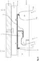
- Fig. 1 shows schematically in a cross section a section from a ceiling covering 1.
- the ceiling covering 1 comprises a plurality of panels which are connected to one another by means of their corresponding connecting profiles 2.
- Fig. 1 shows two panels, a first panel 1a and a second panel 1b, which are connected to one another via their corresponding locking profiles 2 arranged on the longitudinal side.
- a mounting clip 3 is arranged, which engages with a receptacle 4a on a lower groove cheek 5 of the corresponding locking profile 2 of the first panel 1a.
- the lower groove cheek 5 rests on the receptacle 4a.
- the corresponding locking profile 2 is designed as a 5G connection, in which a spring element 6 is locked in a groove 7 in the lower groove cheek 5 and in a groove 8 on the second panel 1b.
- the mounting clip 3 has a flat base body 9.
- a first leg 4 extending perpendicular to the surface protrudes from the surface 3a of the base body 9 facing the panels 1a, 1b in the direction of the first and second panels 1a, 1b.
- the first leg 4 comprises a holding section 10 and a receiving section with the receiving part 4a.
- the holding section 10 is largely aligned parallel to the surface 3 a of the mounting clip 3.
- the mounting clip 3 is movably supported by means of two tabs 32 on a construction rail 12 of a substructure.
- the construction rail 12 is firmly connected to a ceiling 13 by means of a screw connection 14.
- the mounting clip 3 is movably supported in the longitudinal axis direction (L) of the construction rail 12 via the tabs 32.
- the lower groove cheek 5 is in turn supported displaceably on the receptacle 4a, so that the ceiling covering 1 made from the panels 1a, 1b can be moved along its plane in four directions. The ceiling covering 1 is thus completely floating.
- the fall arrest device 15 is formed via the groove 7 in the lower groove cheek 5, the groove 8a in the tongue 8 and the spring element 6 engaging in both grooves 7, 8a.
- the spring element 6 prevents the lower groove cheek from slipping out 5 from the corresponding locking profile 2, so that the first panel 1 a is also held on the ceiling 13. This also reliably prevents a domino effect.
- the spring element 6 is prevented from being separated from the corresponding locking profile 2, so that the second panel 1b or a domino effect is reliably prevented.
- Fig. 2 shows a schematic cross-section through a ceiling covering 1 in the area of panels with corresponding locking profiles 2 arranged along the length.
- the arrangement of the ceiling covering 1, the construction rail 12 and the first and second panels 1a, 1b with the corresponding locking profiles 2 is identical to the illustration in FIG Fig. 1 .
- the mounting of the mounting clip 3 on the construction rail 12 is also identical.
- a second leg 28 protruding from the surface 3a of the base body 9 of the mounting clip 3 is arranged on the mounting clip 3.
- the second leg 28 has a locking body 16 which extends into a locking body receptacle 17 designed as a groove.
- the latching body receptacle 17 is arranged in a second panel 1b of the second row of panels.
- the illustrated embodiment of the fall protection device 15 prevents in particular a domino effect, since when the first panel 1a is detached it can fall off the ceiling 13, but the second panel 1b remains securely attached to the ceiling 13 via the latching body 16 and the latching body receptacle 17.
- Fig. 3 shows a further embodiment of the fall protection device 15.
- the structural design of the ceiling 13, structural rail 12 and the attachment of the mounting clip 3 to the structural rail 12 and the corresponding locking profile 2 is with the structural design of Fig. 1 and 2 identical.
- the latching body 16 is not arranged on a separate second leg 28 on the mounting clip 3, but extends out of the holding section 10 of the first leg 4. In this embodiment too, a domino effect is prevented in particular when the first panel 1a is detached, since that second panel 1b is held via the locking body 17.
- Fig. 4 shows schematically a cross section through a ceiling covering 1.
- the structural construction of ceiling 13, construction rail 12, mounting clip 3 and ceiling covering 1 is identical to that in FIG Fig. 1-3 structure described identical.
- the fall arrester 15 is designed here as a web 18 extending from the base body 9 of the mounting clip 3, which engages in a locking body receptacle 17 designed as a groove 19, which is arranged on the underside 1c of the first panel 1a.
- Fig. 5 shows a further embodiment of the ceiling covering 1 according to the invention.
- the structural construction of ceiling 13, construction rail 12, mounting clip 3, ceiling covering 1 and locking profile 2 is identical to that shown in FIG Fig. 1-4 structure described identical.
- the mounting clip 3 has a second web 18a which engages in a second groove 19a arranged on the second panel 1b and designed as a latching body receptacle 17 on the underside.
- the fall protection 15 can also be formed by a second web 18a with a second groove 19a, ie without a first web 18 and first groove 19.
- Fig. 6 shows a further embodiment of the fall protection device 15, which reliably prevents the first panel 1a from falling off.
- the lower groove cheek 5 of the first panel 1 a is screwed to the mounting clip 3 by means of a connecting means - here a screw 21.
- the screw is mounted in an elongated hole (not shown here) in the mounting clip 3 transversely to the longitudinal axis direction of the construction rail 12.
- Fig. 7 shows a construction rail 12, which is formed as a bent sheet metal.
- the Construction rail 12 has a U-shaped base body 33 in cross section.
- the free ends of the profile legs 20 of the U are angled at a 90 ° angle from the profile leg 20 and form webs 34.
- the two webs 34 are designed to accommodate the mounting clip 3.
- the mounting clip is in Fig. 8 shown.
- the mounting clip 3 has the flat base body 9, from the top side 3b of which two first legs 4 with a holding section 10 and a receptacle 4a extend.
- the holding section 10 extends largely perpendicular to the surface 3a of the flat base body 9.
- the first legs 4 are thus largely L-shaped.
- Two openings 9a are also shown, through which the tabs 32 extending out of the underside 3c of the flat base body 9 are visible.
- the tabs 32 are also L-shaped in cross section.
- Fig. 9 shows a retaining clip 11 which can be used, for example, to assemble a first row of panels 1a.
- the retaining clip 11 is fastened, in particular screwed, to the side of the panels 1a which is arranged towards the wall / ceiling in the assembled state.
- the retaining clip 11 has an elongated hole 22 which is arranged centrally on the retaining clip 11 here.
- the retaining clip 11 has a gripping leg 23 on each of its transverse edges 11a for gripping around the construction rail and on its longitudinal sides two webs 24 for engaging in the profile of the construction rail 12.
- Figures 10a and 10b show a further embodiment for a fall protection device 15, which is designed as an end strip 24.
- the end strip 24 has a base body 25 and a retaining strip 26.
- the end strip 24 shown here is designed for mounting on the wall and for securing a ceiling covering 1 or a wall covering.
- the base body 25 is fastened to a wall with a mounting side 30, for example by means of a screw or adhesive connection.
- the base body 25 has a latching body receptacle 29.
- a latching body - here as a latching strip 27 - is formed on the retaining strip 26, which is designed to snap into the latching body receptacle 29 on the base body 25.
- the base body 25 is attached to the adjacent wall (not shown here).
- the retaining strip 26 is then introduced with its locking strip 27 into the locking body receptacle 29.
- the base body 25 is arranged on the wall in such a way that the retaining strip 26 with its upper side 26a on the Ceiling covering 1 is applied. In this way, on the one hand, a fall of the first panels 1a, ie ceiling panels arranged on the wall or wall panels arranged on the ceiling, is reliably prevented from falling.
- Figure 11 shows schematically in a cross section a further embodiment of a wall and ceiling covering 1 with a mounting clip 3 which has a fall protection device 15.
- a first and a second panel 1 a, 1 b are shown, which are connected to one another without glue via corresponding locking profiles 2.
- the corresponding locking profiles 2 are designed as rotary profiles.
- Both panels 1a, 1b are designed as acoustic panels, each of which comprises a carrier plate 35 with a decorative coating (not shown here) in the area of the visible side S and an absorber 36 arranged on the rear.
- the undersides 1c of the panels 1a, 1b are thus largely formed exclusively by the absorber 36.
- the connected panels 1 a, 1 b are connected with a mounting clip 3.
- the mounting clip 3 has a flat base body 9 with a holding section 10 protruding perpendicularly from the base body 9.
- the holding section 10 is followed by the receptacle 4a, which is arranged at an angle ⁇ of 90 ° to the holding section 10.
- the holding section 10 and the receptacle 4a together form the first leg 4.
- a latching body 16 is arranged.
- the locking body 16 is arranged at an angle ⁇ of greater than 90 °, here of 140 °, to the holding section.
- a free end 16a of the locking body 16 thus points in the direction of the visible side S of the second panel 1b.
- a latching body receptacle 17 is arranged in the second panel 1b.
- the locking body 16 lies in the locking body receptacle 17.
- the locking body receptacle 17 is designed as an enlargement of the groove base 37 of the tongue 8.
- the locking body receptacle 17 extends here over the entire length of the panel 1a, 1b.
- Locking of the second panel 1b on the mounting clip 3 is achieved via the free end 4b of the receptacle 4 in the region of the underside 8b of the spring 8 and the catch body 16 resting in the catch body receptacle 17.
- first panel 1a When the first panel 1a is detached, it rotates out of the locking profile 2.
- the associated dissolution of the locking connection does not cause a domino effect and thus the second panel falling off, since the second panel 1b remains hanging on the mounting clip 3 due to the locking via the latching body 16 and the free end 4b of the receptacle 4.
- Figures 12a and 12b show schematically in a cross section a further embodiment of a wall and ceiling covering 1 with a mounting clip 3, which has a fall protection 15. It represents Figure 12a the beginning of the locking process of the locking profiles 2 and the piercing of the locking body 16 into the absorber 36.
- the locking body 16 is arranged in a first half of the holding section 10 and positioned at an angle ⁇ of 90 ° to the holding section 10.
- the latching body 16 can experience a bending movement during the locking movement, so that here in particular the free end 16a of the latching body 16 is moved.
- the further structural design corresponds to the structural design of the panels 1a, 1b and the mounting clip 3 from Figure 11 .
- Figures 13a and 13b show a further embodiment of a wall and ceiling covering 1 with a mounting clip 3 with fall protection 15, also schematically in a cross section. It shows Figure 13a again the beginning of the locking process of the locking profiles 2 during Figure 13b shows the panels 1a, 1b that are completely joined together without glue. From the embodiment in Figure 12a and Figure 12b This embodiment differs in that the latching body 16 is in its starting position ( Figure 13a ) arranged at an angle ⁇ greater than 90 ° to the holding section 10 and a slot-shaped locking body receptacle 17 for penetration of the locking body 16 is introduced in the absorber 36. When the locking body 16 penetrates into the locking body receptacle 17, the locking body experiences 16 a bend (not shown here).
- the further structural design of the first and second panels 1a, 1b and the mounting clip 3 corresponds to the embodiments from FIG Figure 12a and Figure 12b .
- FIG 14 shows schematically in a cross section a further embodiment of a wall and ceiling covering 1 with a mounting clip 3 with fall protection 15.
- two locking bodies 16 are arranged as fall protection 15, which are designed as pointed thorns.
- the locking body receptacles 17 are produced by the penetration of the thorns into the second panel 1b.
- Both spikes (latching body 16) are arranged here at an angle ⁇ equal to 90 ° between their central longitudinal axis (shown in dashed lines) and the holding section 10.
- a first large locking body 16 is arranged in the first half of the holding section 10 and the second locking body 16 is arranged in the second half of the holding section 10, ie in the region of the receptacle 4a.
- the first large latching body 16 is thus arranged in the absorber 36, while the small, second latching body 16 is arranged in the carrier plate 35 of the second panel 1b.
- the fall protection 15 can be formed with only one locking body 16 (mandrel).
- the latter can, for example, either engage in the absorber 36 or in the carrier plate 35.
- two locking bodies 16 designed as spikes in a panel 1a, 1b without an absorber can be arranged without an absorber.
- the size of the thorns can be tailored to the respective type of material.
- the locking bodies can be made smaller, in particular shorter, so that the depth of penetration into the material is limited.
- the locking bodies can be made larger, in particular longer, in order to enable a penetration depth sufficient to hold the panel.
- FIGS. 15a and 15b show schematically in a cross section a further embodiment of a wall and ceiling covering 1 with a mounting clip 3 with fall protection 15.
- the latching body 16 is positioned in the second half of the holding section 10.
- Both figures show three alternatively feasible orientations of the free end 16a.1 to 16a.3 of the latching body 16.
- the free end 16a.1 In a first position, the free end 16a.1 is at an angle ⁇ greater than 90 °; in a second position, it is free End 16a.2 at an angle ⁇ equal to 90 ° and in a third position the free end 16a.3 is aligned with the holding section 10 at an angle ⁇ less than 90 °.
- the locking body receptacle 17 is oversized.
- the third position of the free end 16a.3 is particularly advantageous since the free end 16a.3 is arranged in the immediate vicinity of a side wall 17b of the locking body receptacle 17.
- the embodiment from Figure 15b differs from the embodiment Figure 15a in that the locking body receptacle 17 in the embodiment of Figure 15a is designed as a simple slot which is oriented obliquely to the visible sides S, while the locking body receptacle 17 in the embodiment of Figure 15b straightened in its lower side wall 17b, ie provided with a perpendicular section 17a (to the visible sides). This significantly facilitates the introduction of the locking bodies 16 into the locking body receptacle 17.
- Figure 16 shows schematically in a cross section a further embodiment of the wall and ceiling covering 1 with a mounting clip 3 with fall protection 15.
- this embodiment is between the bottom 1c of the second panel 1b and the surface 3a of the mounting clip 3, more precisely between the surface 3a of the flat base body 9, which faces the underside 1c of the second panel 1b, an adhesive 38, for example on a PU basis, is arranged that connects the second panel 1b to the mounting clip 3.
- the mounting clip 3 does not have any latching bodies 16 and, in addition, no latching body receptacle 17 is formed.
- This embodiment of the fall protection device 15 can be implemented as an alternative, but in particular in addition, to the embodiments described above and of course also in the case of panels 1a, 1b which are not designed as acoustic panels and thus do not have an absorber 36.
- the further structural design of the mounting clip 3 (first leg 4, holding section 10, receptacle 4a) and the two panels 1a, 1b (visible side S, carrier plate 35, absorber 36, corresponding locking profiles 2) corresponds to the design from FIGS Figures 11-15b .
- the locking bodies 16 shown all extend in the opposite direction to the receptacle 4a.
- the latching bodies 16 can preferably be as structural bodies protruding from the surface of the holding section 10, in particular as from the holding section 10 bent out structure may be formed.
- the fall protection devices 15 shown can be used both on conventional panels 1a, 1b (with decorative cover layer, carrier plate and, if applicable, counter-tension) and on panels 1a, 1b, which are designed as acoustic panels (with decorative cover layer, carrier plate, or optionally, counter-tension and absorber).
Description
Die Erfindung betrifft ein Verfahren zur Herstellung eines schwimmend gelagerten Decken- oder Wandbelags gemäß Anspruch 1. Weiter betrifft die Erfindung ein Montagesystem zum Herstellen eines schwimmend verlegten Wand- oder Deckenbelags nach Anspruch 6.The invention relates to a method for producing a floating ceiling or wall covering according to
Befestigungssysteme für Wand- und Deckenbeläge sind beispielsweise aus der
Wand- und Deckenbeläge mit einer zumindest teilweise schwimmenden Verlegung sind beispielsweise aus der
Der Clip ist so an der Clipaufnahme angeordnet, dass sich das Paneel sowohl quer zur Längsachsenrichtung als auch in Längsachsenrichtung des Paneels am Clip bewegen kann. Dabei wird die Bewegungsmöglichkeit quer zur Längsachsenrichtung des Paneels über eine gegenüber der Länge des Clips längere Clipaufnahme im Paneel erzeugt. Insofern ist jedoch die Bewegung quer zur Längsachsenrichtung nur stark eingeschränkt möglich, da der zur Verfügung stehende Platz in der Clipaufnahme stark begrenzt ist. Eine weitere Schwierigkeit besteht in der Sicherung von an Decken und Wänden angeordneten Paneelen, die mit korrespondierenden Verriegelungsprofilen verbunden sind, da beim unbeabsichtigten Lösen eines Paneels ein Dominoeffekt entsteht, aufgrund dessen große Abschnitte der Paneelfläche oder sogar die gesamte Paneelfläche von der montierten Wand oder Decke abfällt.The clip is arranged on the clip holder in such a way that the panel can move both transversely to the direction of the longitudinal axis and in the direction of the longitudinal axis of the panel on the clip. The possibility of movement transversely to the longitudinal axis direction of the panel is generated by means of a clip holder in the panel that is longer than the length of the clip. In this respect, however, the movement transverse to the longitudinal axis direction is only possible to a very limited extent, since the space available in the clip holder is very limited. Another difficulty lies in securing panels arranged on ceilings and walls, which are connected with corresponding locking profiles, because a domino effect arises when a panel is accidentally detached, due to which large sections of the panel surface or even the entire panel surface falls off the mounted wall or ceiling.
Der Erfindung liegt somit die Aufgabe zugrunde, ein verbessertes Verfahren und ein verbessertes Montagesystem zum Herstellen eines schwimmend montierten Wand- oder Deckenbelages bereit zu stellen, mit dem ein gegen unbeabsichtigtes Ablösen gesicherter Wand- oder Deckenbelag hergestellt werden kann. Ferner ist es Aufgabe, einen entsprechenden Wand- oder Deckenbelag bereit zu stellen.The invention is therefore based on the object of providing an improved method and an improved mounting system for producing a floating wall or ceiling covering with which a wall or ceiling covering secured against unintentional detachment can be produced. It is also a task to provide a suitable wall or ceiling covering.
Die Erfindung löst die Aufgabe durch ein Verfahren mit den Merkmalen des Anspruchs 1 und ein Montagesystem mit den Merkmalen des Anspruchs 6.The invention achieves the object by a method with the features of
Bei Wand- und Deckenbelägen, die mit Paneelen gebildet werden, die über (leimlos verbindbare) korrespondierende Verriegelungsprofile verbunden sind, wird immer nur ein (erster) Montageclip mit Aufnahme an einem ersten Paneel (erste Paneelreihe) angeordnet und das zweite Paneel (zweite Paneelreihe) hält mittels der Verriegelungsprofile an dem ersten Paneel. Um einen Dominoeffekt (unbeabsichtigtes Ablösen einer Vielzahl von Paneelen) zu verhindern, bildet die erfinderische Absturzsicherung entweder eine zusätzliche Verbindung/Verriegelung des zweiten Paneels an dem (dem ersten Paneel zugeordneten) Montageclip aus, wodurch ein Dominoeffekt verhindert wird, oder sie bildet eine zusätzliche Verbindung zwischen dem ersten Paneel und dem (ersten) Montageclip oder zwischen dem ersten Paneel und dem zweiten Paneel aus, wodurch ein unbeabsichtigtes Ablösen eines Paneels und somit ebenfalls auch ein Dominoeffekt verhindert wird.In the case of wall and ceiling coverings that are formed with panels that are connected via (gluelessly connectable) corresponding locking profiles, only one (first) mounting clip with a receptacle is always arranged on a first panel (first row of panels) and the second panel (second row of panels) holds on to the first panel by means of the locking profiles. In order to prevent a domino effect (unintentional detachment of a large number of panels), the inventive fall protection device either forms an additional connection / locking of the second panel to the mounting clip (assigned to the first panel), thereby preventing a domino effect, or it forms an additional connection between the first panel and the (first) mounting clip or between the first panel and the second panel, whereby an unintentional detachment of a panel and thus also a domino effect is prevented.
Das erfindungsgemäße Verfahren zur Herstellung eines schwimmend gelagerten Decken- oder Wandbelags umfassend eine Paneelfläche mit einer Vielzahl von Paneelen, die an den Längsseiten und/oder Querseiten mittels zueinander korrespondierender und klebstofffrei verbindbarer Verriegelungsprofile miteinander verbunden werden, wobei die korrespondierenden Verriegelungsprofile beim leimlosen Verbinden von zwei Paneelen sowohl einen Höhenversatz zwischen den Oberflächen der Sichtseiten der beiden Paneele als auch ein Ausbilden einer Fuge zwischen den Paneelen verhindern, weist die Schritte auf: Anordnen von ersten Paneelen einer ersten Paneelreihe an Konstruktionsschienen mittels eines Montageclips, wobei die Montageclips in Längsachsenrichtung der Konstruktionsschiene beweglich an der Konstruktionsschiene gelagert und anschließend entlang den Konstruktionsschienen mit einer Aufnahme auf die zweite Seite des ersten Paneels geschoben werden, jeder Montageclip mit einer Aufnahme in eine Ausnehmung der ersten Paneele eingreift, so dass das erste Paneel quer zur Längsachsenrichtung der Konstruktionsschienen an der Aufnahme beweglich gelagert sind, Verbinden eines zweiten Paneels einer zweiten Paneelreihe mit den ersten Paneelen mittels der längsseitigen Verriegelungsprofile, wobei gleichzeitig mit dem Verbinden eine Absturzsicherung angeordnet wird, die das Lösen des zweiten Paneels von der Konstruktionsschiene verhindert, wobei die Absturzsicherung im Bereich der verbundenen Verriegelungsprofile angeordnet wird.The method according to the invention for the production of a floating ceiling or wall covering comprising a panel surface with a large number of panels which are connected to one another on the longitudinal and / or transverse sides by means of locking profiles that correspond to one another and can be connected without adhesive, the corresponding locking profiles when two panels are connected without glue To prevent both a height offset between the surfaces of the visible sides of the two panels and the formation of a joint between the panels, has the following steps: arranging the first panels of a first row of panels on construction rails by means of a mounting clip, the mounting clips being movable on the longitudinal axis of the construction rail Construction rails are stored and then pushed along the construction rails with a receptacle on the second side of the first panel, each mounting clip with a receptacle in a recess ng of the first panels engages so that the first panel is movably mounted on the receptacle transversely to the direction of the longitudinal axis of the construction rails, connecting a second panel of a second row of panels with the first panels by means of the longitudinal locking profiles, a fall protection being arranged at the same time as the connection, which prevents the second panel from being detached from the construction rail, the fall protection being arranged in the area of the connected locking profiles.
Das erfindungsgemäße Verfahren ermöglicht eine besonders einfache und werkzeuglose Montage eines Decken- oder Wandbelages auf den Konstruktionsschienen. Dabei werden erste Paneele einer ersten Paneelreihe mit einer ersten Längsseite, die im Bereich einer an die Paneelfläche angrenzenden Raumbegrenzungsfläche angeordnet ist, an den Konstruktionsschienen befestigt. Dies erfolgt entweder mittels der Montageclips oder durch bspw. verdeckte, unterseitig montierbare Halteclips. Zur weiteren Montage wird ein Montageclip an der Konstruktionsschiene angeordnet, bspw. mittels einer Drehbewegung um eine senkrecht zur Paneeloberfläche stehende Drehachse, so dass der Montageclip mit bspw. zwei Laschen beweglich auf der Konstruktionsschiene gelagert ist. Anschließend wird der Montageclip entlang der Konstruktionsschiene mit einer Aufnahme auf die der Raumbegrenzungsseite gegenüberliegende zweite Seite des ersten Paneels geschoben, so dass das erste Paneel an der Aufnahme in Längsachsenrichtung des Paneels beweglich gelagert anliegt.The method according to the invention enables a particularly simple and tool-free installation of a ceiling or wall covering on the construction rails. There First panels of a first row of panels are fastened to the construction rails with a first longitudinal side which is arranged in the area of a space delimiting surface adjoining the panel surface. This is done either by means of the mounting clips or, for example, by concealed retaining clips that can be mounted on the underside. For further assembly, a mounting clip is arranged on the construction rail, for example by means of a rotary movement around an axis of rotation perpendicular to the panel surface, so that the assembly clip is movably supported on the construction rail with two tabs, for example. The mounting clip is then pushed along the construction rail with a receptacle onto the second side of the first panel opposite the room delimitation side, so that the first panel rests movably on the receptacle in the direction of the longitudinal axis of the panel.
Nachfolgend wird das zweite Paneel einer zweiten Paneelreihe mittels der längsseitigen Verriegelungsprofile am längsseitigen Verriegelungsprofil des ersten Paneels angeordnet und mit diesem verriegelt. Zur Befestigung der der ersten Paneelreihe gegenüberliegenden zweiten Seite des zweiten Paneels wird wiederum ein Montageclip an der Konstruktionsschiene montiert und mit seiner Aufnahme auf die zweite Seite des zweiten Paneels geschoben.Subsequently, the second panel of a second row of panels is arranged on the longitudinal locking profile of the first panel by means of the longitudinal locking profiles and locked to it. To fasten the second side of the second panel opposite the first row of panels, a mounting clip is again mounted on the construction rail and pushed with its receptacle onto the second side of the second panel.
Weitere Paneelreihen werden entsprechend der Montage der zweiten Paneelreihe montiert, wobei die letzte Paneelreihe einer Paneelfläche bspw. entsprechend der ersten Paneelreihe an der der Raumbegrenzungsfläche zugewandten Seite ebenfalls mit einem Montageclip oder bspw. mit einem unterseitig und verdeckt montierten Halteclip an der Konstruktionsschiene befestigt werden kann.Further rows of panels are installed in accordance with the installation of the second row of panels, with the last row of panels of a panel surface, for example, corresponding to the first row of panels, on the side facing the room delimiting surface, also being fastened to the construction rail with a mounting clip or, for example, with a retainer clip mounted on the underside and concealed.
Die Lagerung der Paneele an den Montageclips, die wiederum an der Konstruktionsschiene beweglich gelagert sind, ermöglicht eine vollständig schwimmende Lagerung und somit eine unbehinderte Bewegung der Paneelfläche zwischen den Raumbegrenzungsflächen.The mounting of the panels on the mounting clips, which in turn are movably mounted on the construction rail, enables a completely floating mounting and thus an unimpeded movement of the panel surface between the room boundary surfaces.
Unter einer vollständig schwimmenden Lagerung wird verstanden, dass die Paneelfläche sich in ihrer Ebene in vier 90° zueinander versetzte Richtungen ungehindert bis zu den jeweiligen angrenzenden Raumbegrenzungsflächen bewegen kann.A completely floating mounting is understood to mean that the panel surface can move unhindered in its plane in four directions offset by 90 ° to one another as far as the respective adjacent room delimitation surfaces.
Dabei kann die Bewegung entlang der Längsachse der Paneele, d.h. quer zur Längsachse der Konstruktionsschienen, erfolgen, indem das Paneel an der Aufnahme des Montageclips entlang rutscht, d.h. seine Position gegenüber dem Montageclip verändert. Die Bewegung der Paneelfläche in Längsachsenrichtung der Konstruktionsschiene erfolgt gemeinsam mit dem Montageclip, indem der Montageclip an der Konstruktionsschiene entlang gleitet. Bei der Bewegung der Paneelfläche in Längsachsenrichtung erfolgt demnach keine Relativbewegung zwischen Montageclip und Paneel.The movement can take place along the longitudinal axis of the panels, i.e. transversely to the longitudinal axis of the construction rails, in that the panel slides along the receptacle of the mounting clip, i.e. changing its position in relation to the mounting clip. The movement of the panel surface in the direction of the longitudinal axis of the construction rail takes place together with the mounting clip in that the mounting clip slides along the construction rail. When the panel surface is moved in the direction of the longitudinal axis, there is accordingly no relative movement between the mounting clip and the panel.
Gattungsgemäße Paneele umfassen Holzwerkstoffe, insbesondere Holzwerkstoffplatten, die als Wand- oder Deckenbelag eingesetzt werden. Unter Holzwerkstoffen werden dabei insbesondere die klassischen Holzwerkstoffe wie Sperrholzplatten und Furnierholzplatten oder partikelbasierte Holzwerkstoffe, wie bspw. Faserplatten, Spanplatten oder OSB-Platten verstanden. Zudem können gattungsgemäße Paneele auch Wood-Plastic-Composites umfassen, d.h. bspw. mittels Extrusion oder Spritzgussverfahren hergestellte Werkstoffe umfassen, die Holzpartikel enthalten. Gattungsgemäße Paneele umfassen vorzugsweise eine Beschichtung. Die Beschichtung kann bspw. Echtholz, Laminat (DPL: direct pressure laminate, direkt verpresstes Laminat, CPL: continues pressure laminate, kontinuierlich verpresste Laminate, HPL: high pressure laminate, Hochdrucklaminate), Lack, bspw. aufgetragen durch Direktdruck oder Indirektdruck, eine Kunststoff- oder Plexiglasplatte oder -folie, eine Metallplatte, eine WPC-Platte oder -folie oder Kombinationen hiervon umfassen.Panels of the generic type include wood-based materials, in particular wood-based panels, which are used as wall or ceiling covering. Wood-based materials are understood to mean, in particular, the classic wood-based materials such as plywood panels and veneered wood panels or particle-based wood-based materials, such as, for example, fiberboard, chipboard or OSB panels. In addition, generic panels can also comprise wood-plastic composites, i.e., for example, comprise materials produced by means of extrusion or injection molding processes that contain wood particles. Panels of the generic type preferably comprise a coating. The coating can be, for example, real wood, laminate (DPL: direct pressure laminate, directly pressed laminate, CPL: continues pressure laminate, continuously pressed laminate, HPL: high pressure laminate, high pressure laminate), varnish, for example applied by direct printing or indirect printing, a plastic - or Plexiglas plate or foil, a metal plate, a WPC plate or foil or combinations thereof.
Das bedeutet, dass gattungsgemäße Paneele in jedem Fall mehrschichtig ausgebildet sein können. Dabei kann das Paneel selbst mehrschichtig, bspw. aus einer Holzwerkstoffplatte und einer Beschichtung ausgebildet sein. Auch ist es möglich, die Holzwerkstoffplatte selbst oder die Beschichtung selbst jeweils mehrschichtig auszubilden.This means that generic panels can in any case have a multilayer design. The panel itself can be multilayered, for example made of a wood-based panel and a coating. It is also possible to design the wood-based panel itself or the coating itself in each case with multiple layers.
Eine besonders bevorzugte Ausführungsform des Paneels ist als Akustikpaneel ausgebildet. Dieses kann neben den oben genannten Holzwerkstoffen auch die genannten Wood-Plastic-Composites (WPC) umfassen. Zudem kann es ebenfalls eine Beschichtung, bspw. eine der oben genannten Beschichtungen umfassen, die insbesondere auf seiner Sichtseite angeordnet sind. Auf der Rückseite, d.h. der der Sichtseite gegenüberliegenden Oberfläche, kann das Akustikpaneel zusätzlich einen Absorber aufweisen, der entweder direkt mit der Trägerplatte oder einem Gegenzug auf der Trägerplatte verbunden ist.A particularly preferred embodiment of the panel is designed as an acoustic panel. In addition to the wood-based materials mentioned above, this can also include the wood-plastic composites (WPC) mentioned. In addition, it can also include a coating, for example one of the above-mentioned coatings, which are arranged in particular on its visible side. On the back, ie the surface opposite the visible side, the acoustic panel can additionally have an absorber which either is connected directly to the carrier plate or a counter-pull on the carrier plate.
Der Absorber weist insbesondere eine Dichte zwischen 100 kg/m3 und 300 kg/m3 auf. Er ist vorzugsweise 10mm bis 12mm dick während die Trägerplatte insbesondere im Bereich von 6 mm bis 14 mm dick ist. Der Absorber kann bspw. als Holzwolleplatte ausgebildet sein. Auch kann der Absorber bspw. ein Fasergemisch aus Holz und Kunststofffasern umfassen.In particular, the absorber has a density between 100 kg / m 3 and 300 kg / m 3 . It is preferably 10 mm to 12 mm thick while the carrier plate is in particular in the range from 6 mm to 14 mm thick. The absorber can, for example, be designed as a wood wool panel. The absorber can also comprise, for example, a fiber mixture made from wood and plastic fibers.
Paneele im Sinne der Erfindung kennzeichnen sich dadurch aus, dass sie plattenförmig ausgebildet sind und an ihren Längsseiten und an ihren Querseiten zueinander korrespondierende Verriegelungsprofile zum klebstofffreien und fugenlosen Verbinden aufweisen, wobei zumindest die Längsseiten zueinander und die Querseiten zueinander korrespondierende Verriegelungsprofile aufweisen. Alternativ können auch jeweils eine Quer- und eine Längsseite identische Profile aufweisen, so dass ein erstes Paneel mit einer Querseite mit einer Längsseite eines zweiten Profils verbunden werden kann. Unter einer Paneelfläche ist eine Mehrzahl von Paneelen zu verstehen, die über ihre korrespondierenden Verbindungsmittel miteinander verbunden sind und beispielsweise eine fugenlose Oberfläche, einen Oberflächenbelag, ausbilden.Panels in the sense of the invention are characterized by the fact that they are plate-shaped and have locking profiles that correspond to one another on their long sides and their transverse sides for adhesive-free and seamless connection, at least the long sides having locking profiles that correspond to one another and the transverse sides. Alternatively, a transverse side and a longitudinal side can each have identical profiles, so that a first panel can be connected with a transverse side to a longitudinal side of a second profile. A panel surface is to be understood as meaning a plurality of panels which are connected to one another via their corresponding connecting means and, for example, form a seamless surface, a surface covering.
Die korrespondierenden Verriegelungsprofile sind insbesondere als Drehprofile, Schwenkprofile und/oder Drehschwenkprofile ausgebildet. Auch können die Verriegelungsprofile als so genannte Druckknopfprofile ausgebildet sein. Alternativ oder ergänzend können sowohl die längsseitigen als auch die querseitigen Verriegelungsprofile eine so genannte 5G-Verriegelung aufweisen. Die Verriegelung von zwei Paneelen erfolgt dabei derart, dass die korrespondierenden Verriegelungsprofile beim leimlosen Verbinden (Verriegeln) von zwei Paneelen sowohl einen Höhenversatz zwischen den Oberflächen der Sichtseiten der beiden Paneele als auch ein Ausbilden einer Fuge zwischen den Paneelen verhindern.The corresponding locking profiles are designed in particular as rotary profiles, pivot profiles and / or rotary pivot profiles. The locking profiles can also be designed as so-called push-button profiles. As an alternative or in addition, both the longitudinal and the transverse locking profiles can have what is known as 5G locking. The locking of two panels takes place in such a way that the corresponding locking profiles prevent both a height offset between the surfaces of the visible sides of the two panels and the formation of a joint between the panels when connecting (locking) two panels without glue.
Unter den ersten Paneelen einer ersten Paneelreihe werden Paneele verstanden, die über korrespondierende Verriegelungsprofile an ihren Querseiten (kurze Seitenkante) miteinander verbunden und Teil eines Wand- oder Deckenbelages sind. Dabei ist eine erste Paneelreihe eine erste oder letzte Paneelreihe einer Paneelfläche. Die erste Paneelreihe kann somit eine die Paneelfläche abschließende Paneelreihe sein, d.h. bspw. mit einer ihrer Längsseiten an eine Raumbegrenzungsfläche angrenzen.The first panels of a first row of panels are understood to mean panels that are connected to one another on their transverse sides (short side edge) via corresponding locking profiles and are part of a wall or ceiling covering. A first row of panels is a first or last row of panels of a panel surface. The first row of panels can thus be a row of panels closing off the panel surface, ie, for example, with one their long sides border on a room delimitation area.
Bei Wand- oder Deckenbelägen aus Paneelen mit korrespondierenden Verriegelungsprofilen ist es notwendig, dass die erste Paneelreihe mindestens zwei direkte Verbindungspunkte mit der Unterkonstruktion aufweist, nämlich zum einen im Bereich der Außenseite (bspw. der der Raumbegrenzungsfläche zugewandten Seite) der ersten Paneele und eine Verbindung im Bereich des korrespondierenden Verriegelungsprofils mit einem zweiten Paneel. Die der Raumbegrenzungsfläche zugewandte Verbindung kann beispielsweise ebenfalls mit dem Montageclip erfolgen, vorzugsweise kann hierzu jedoch ein Halteclip verwendet werden, der verdeckt an der Unterseite des Paneels im wandseitigen Bereich angeordnet wird und mit der Konstruktionsschiene in Eingriff kommt.In the case of wall or ceiling coverings made of panels with corresponding locking profiles, it is necessary for the first row of panels to have at least two direct connection points with the substructure, namely on the one hand in the area of the outside (e.g. the side facing the room delimitation area) of the first panels and a connection in the Area of the corresponding locking profile with a second panel. The connection facing the room delimitation surface can also be made with the mounting clip, for example, but preferably a retaining clip can be used for this purpose, which is arranged concealed on the underside of the panel in the wall-side area and comes into engagement with the construction rail.
Unter dem Montageclip ist ein Befestigungsmittel zu verstehen, dass eine bewegliche Verbindung zwischen den Konstruktionsschienen der Unterkonstruktion und der Paneelfläche herstellt. Die bewegliche Lagerung des Montageclips an den Konstruktionsschienen erfolgt bspw. derart, dass der Montageclip Laschen zum Umgreifen von Abschnitten der Konstruktionsschiene aufweist, so dass der Montageclip entlang der Längsachsenrichtung der Konstruktionsschienen an den Konstruktionsschienen verschoben werden kann.The mounting clip is to be understood as a fastening means that creates a movable connection between the construction rails of the substructure and the panel surface. The movable mounting of the mounting clip on the construction rails takes place, for example, in such a way that the mounting clip has tabs for grasping around sections of the construction rail, so that the assembly clip can be shifted along the longitudinal axis direction of the construction rails on the construction rails.
Zum Anordnen des Montageclips an dem Paneel ist es vorgesehen, dass der Montageclip mit einer Aufnahme in eine Ausnehmung des Paneels eingreift. Die Aufnahme kann insbesondere einen aus einer Oberfläche des Montageclips herausragenden ersten Schenkel aufweisen, der die Aufnahme umfasst.To arrange the mounting clip on the panel, it is provided that the mounting clip engages with a receptacle in a recess of the panel. The receptacle can in particular have a first leg which protrudes from a surface of the mounting clip and which comprises the receptacle.
Zur Lagerung der Paneele an der Aufnahme ist vorzugsweise vorgesehen, dass ein Abschnitt des ersten Schenkels einen Abschnitt einer Nutwange, bspw. einer unteren Nutwange, des Verriegelungsprofils umgreift. Dabei liegt die Nutwange mit einem Abschnitt auf der Aufnahme auf bzw. an dieser an und kann sich entlang der Aufnahme bewegen.To mount the panels on the receptacle, it is preferably provided that a section of the first leg engages around a section of a groove cheek, for example a lower groove cheek, of the locking profile. A section of the groove cheek rests on or against the receptacle and can move along the receptacle.
Die vollständig schwimmende Lagerung erfolgt somit derart, dass die Paneelfläche sich als Ganzes in Längsachsenrichtung der Konstruktionsschienen gemeinsam mit den Montageclips bewegen kann, während die Paneelfläche sich in Richtung quer zur Längsachsenrichtung der Konstruktionsschienen bewegt, in dem die auf der Aufnahme des Montageclips aufliegenden Abschnitte des Paneels verschoben werden.The completely floating mounting is thus carried out in such a way that the panel surface as a whole can move in the direction of the longitudinal axis of the construction rails together with the mounting clips, while the panel surface can move in the direction transverse to the direction of the longitudinal axis the construction rails are moved by shifting the sections of the panel resting on the mount of the mounting clip.
Die Konstruktionsschienen weisen insbesondere einen hutartigen Querschnitt auf, d.h., sie weisen einen u-förmigen Grundkörper auf, bei dem die freien Enden der Schenkel in einem Winkel von beispielsweise 90° nach außen abgekantet sein können und in entgegengesetzte Richtung zeigende Stege ausbilden. Die Konstruktionsschienen werden vorzugsweise mit ihrem Grundkörper direkt auf die Wand oder Decke bzw. eine weitere Tragkonstruktion montiert, so dass die Stege beabstandet und weitestgehend parallel zur Wand oder Decke ausgerichtet sind.The construction rails in particular have a hat-like cross-section, i.e. they have a U-shaped base body, in which the free ends of the legs can be bent outwards at an angle of, for example, 90 ° and form webs pointing in the opposite direction. The construction rails are preferably mounted with their base body directly on the wall or ceiling or another supporting structure, so that the webs are spaced apart and aligned largely parallel to the wall or ceiling.
Bei Wand- und Deckenbelägen aus Paneelen mit korrespondierenden Verriegelungsprofilen besteht beim Ablösen eines Paneels von der Unterkonstruktion die Gefahr eines Dominoeffektes. Bei diesem löst sich bspw. ein erstes Paneel von der Unterkonstruktion ab und rutscht aus dem korrespondierenden Verriegelungsprofil des zweiten Paneels heraus. Durch das Auflösen der korrespondierenden Verriegelungsverbindung verlieren die zweiten Paneele einseitig ihre Verbindung mit der Unterkonstruktion, wodurch sich auch diese aus dem Montageclip und der jeweiligen korrespondierenden Verrieglungsverbindung lösen und abfallen.In the case of wall and ceiling coverings made of panels with corresponding locking profiles, there is a risk of a domino effect when a panel is detached from the substructure. In this case, for example, a first panel becomes detached from the substructure and slips out of the corresponding locking profile of the second panel. By dissolving the corresponding locking connection, the second panels lose their connection to the substructure on one side, as a result of which they also detach from the mounting clip and the respective corresponding locking connection and fall off.
Dementsprechend kann es vorkommen, dass bspw. ein versehentlich abgelöstes Paneel im Randbereich einer Paneelfläche große Teile der Paneelfläche bzw. die gesamte Paneelfläche mit abstürzen lässt (Dominoeffekt).Accordingly, it can happen that, for example, an inadvertently detached panel in the edge area of a panel surface causes large parts of the panel surface or the entire panel surface to fall off at the same time (domino effect).
Unter einer Absturzsicherung wird ein Mittel oder eine Vorrichtung verstanden, die zusätzlich zu den Verriegelungsprofilen und der Aufnahme am Montageclip eine weitere Fixierung der Paneele bewirkt, die das Ablösen eines ersten und/oder zweiten Paneels und insbesondere einen Dominoeffekt deutlich erschwert bzw. verhindert.Fall protection is understood to mean a means or a device which, in addition to the locking profiles and the receptacle on the mounting clip, further fixes the panels, which makes the detachment of a first and / or second panel and in particular a domino effect significantly more difficult or impossible.
Unter dem gleichzeitigen Anordnen der Absturzsicherung wird dabei verstanden, dass die Absturzsicherung während des längsseitigen Verbindens des ersten und zweiten Paneels, d.h. bei der Verriegelung der beiden Paneele mittels der Verriegelungsprofile, angeordnet wird. D.h., der Vorgang der Verriegelung und der Anordnung der Absturzsicherung erfolgt zumindest teilweise zeitgleich. Unter einem nachträglichen Anordnen der Absturzsicherung wird verstanden, dass die Einrichtung/Montage der Absturzsicherung nach Abschluss der Verriegelung der Verriegelungsprofile erfolgt. Dementsprechend wird unter vor dem Verbinden verstanden, dass die Absturzsicherung montiert wird, bevor das Verbinden der Verriegelungsprofile erfolgt.The simultaneous arrangement of the fall protection is understood to mean that the fall protection is arranged during the longitudinal connection of the first and second panels, ie when the two panels are locked by means of the locking profiles. In other words, the locking process and the arrangement of the fall protection device take place at least partially at the same time. Under a subsequent arrangement the fall protection means that the installation / assembly of the fall protection takes place after the locking of the locking profiles. Accordingly, before connecting is understood to mean that the fall protection device is installed before the locking profiles are connected.
Nach einer Weiterbildung der Erfindung wird die Absturzsicherung im Bereich des Verriegelungsprofils angeordnet. So kann die Absturzsicherung als Klebemittel ausgebildet sein, das bspw. im Bereich des korrespondierenden Verriegelungsprofils angeordnet wird und diese verklebt. Als Klebemittel können insbesondere Leime eingesetzt werden. Besonders bevorzugt wird die Absturzsicherung bspw. als mechanisches Bauteil ausgebildet, das in das vorhandene Verriegelungsprofil oder unterseitig am Paneel angreift. Dabei kann die Absturzsicherung insbesondere als Rastkörper ausgebildet sein, der in eine an einem Paneel angeordnete Rastkörperaufnahme eingreift.According to a further development of the invention, the fall protection is arranged in the area of the locking profile. Thus, the fall protection can be designed as an adhesive, which is arranged, for example, in the area of the corresponding locking profile and glues it. Glues in particular can be used as adhesives. The fall protection is particularly preferably designed, for example, as a mechanical component which engages the existing locking profile or the underside of the panel. The fall protection device can in particular be designed as a latching body which engages in a latching body receptacle arranged on a panel.
Besonders bevorzugt wird zur Ausbildung einer Absturzsicherung im ersten und/oder zweiten Paneel mindestens eine Rastkörperaufnahme eingebracht, in die ein vorzugsweise am Montageclip angeordneter Rastkörper eingreift. Das Eingreifen erfolgt insbesondere vor oder während des Verriegelns der korrespondierenden Verriegelungsprofile des ersten und zweiten Paneels.Particularly preferably, at least one latching body receptacle, into which a latching body preferably arranged on the mounting clip engages, is introduced in the first and / or second panel to form a fall protection device. The engagement takes place in particular before or during the locking of the corresponding locking profiles of the first and second panels.
Die Rastkörperaufnahme kann insbesondere als Ausnehmung ausgebildet sein. Die Ausnehmung ist besonders bevorzugt als sich in Längsachsenrichtung des Paneels erstreckende Nut ausgebildet. Die Rastkörperaufnahme ist zudem insbesondere als zum Verriegelungsprofil zusätzliche Nut ausgebildet.The locking body receptacle can in particular be designed as a recess. The recess is particularly preferably designed as a groove extending in the direction of the longitudinal axis of the panel. The locking body receptacle is also designed in particular as a groove additional to the locking profile.
Die Rastkörperaufnahme ist bevorzugt im Bereich des Verriegelungsprofils des zweiten Paneels angeordnet. Der hierfür geeignete Rastkörper ist vorzugsweise am Montageclip angeordnet. Er kann nach einer bevorzugten Ausführungsform als zweiter Schenkel vorgesehen sein, der beim Verriegelungsvorgang der Verriegelungsprofile in die Rastkörperaufnahme eingeführt wird, wodurch eine besonders stabile Sicherung des zweiten Paneels erreicht wird.The locking body receptacle is preferably arranged in the area of the locking profile of the second panel. The locking body suitable for this is preferably arranged on the mounting clip. According to a preferred embodiment, it can be provided as a second leg which is inserted into the locking body receptacle during the locking process of the locking profiles, whereby a particularly stable securing of the second panel is achieved.
Alternativ wird der Rastkörper nach einer Weiterbildung der Erfindung am ersten, die Aufnahme umfassenden Schenkel angeordnet. Bei diesen Ausführungsformen wird das Verriegelungsprofil des zweiten Paneels mit dem Verriegelungsprofil des ersten Paneels gekoppelt und gleichzeitig, bspw. bei der durchzuführenden Schwenkbewegung zum Koppeln der Verriegelungsprofile, wird der Rastkörper in die Rastkörperaufnahme eingeführt.Alternatively, according to a further development of the invention, the latching body is arranged on the first leg that encompasses the receptacle. In these embodiments that will The locking profile of the second panel is coupled to the locking profile of the first panel and at the same time, for example, during the pivoting movement to be carried out to couple the locking profiles, the locking body is inserted into the locking body receptacle.
Alternativ oder ergänzend zum Rastkörper und zur Rastkörperaufnahme im Bereich der Verriegelungsprofile wird die Rastkörperaufnahme in die Unterseite des ersten und/oder zweiten Paneels eingebracht. Diese kann ebenfalls als einzelne Ausnehmung oder bspw. als sich in Längsrichtung des Paneels erstreckende Nut erfolgen. Der jeweils dazugehörige Rastkörper kann bevorzugt als sich aus dem Grundkörper des Montageclips herausragender Steg ausgebildet sein.As an alternative or in addition to the locking body and the locking body receptacle in the area of the locking profiles, the locking body receptacle is introduced into the underside of the first and / or second panel. This can also take place as a single recess or, for example, as a groove extending in the longitudinal direction of the panel. The respectively associated latching body can preferably be designed as a web protruding from the base body of the mounting clip.
Bei der Ausbildung der Rastkörperaufnahme im Bereich der Unterseite des ersten Paneels wird der Montageclip bspw. mit einem die Aufnahme umfassenden ersten Schenkel auf eine untere Nutwange des ersten Paneels geschoben und ein am Grundkörper des Montageclips angeordneter erster Steg wird in die Rastkörperaufnahme des ersten Paneels eingeführt. Alternativ oder ebenfalls ergänzend wird beim Einschwenken der Verriegelungsprofile ineinander ein zweiter Steg in eine unterseitige Rastkörperaufnahme am zweiten Paneel eingeführt.When the locking body receptacle is formed in the area of the underside of the first panel, the mounting clip is pushed, for example, with a first leg encompassing the receptacle onto a lower groove cheek of the first panel and a first web arranged on the base body of the mounting clip is inserted into the locking body receptacle of the first panel. Alternatively or also in addition, when the locking profiles are pivoted into one another, a second web is inserted into a latching body receptacle on the second panel on the underside.
Eine weitere Ausführungsform sieht vor, dass beim Montieren des zweiten Paneels an dem ersten Paneel ein Federelement in beide Verriegelungsprofile eindringt, so dass eine Entriegelung verhindert wird. Das Federelement ist hierfür entweder im Verriegelungsprofil des ersten oder des zweiten Paneels montiert. Das Federelement greift bevorzugt in eine Federelementaufnahme, bspw. eine Nut, ein, so dass es im verriegelten Zustand in beide Verriegelungsprofile des ersten und zweiten Paneels eingreift.Another embodiment provides that when the second panel is mounted on the first panel, a spring element penetrates into both locking profiles so that unlocking is prevented. For this purpose, the spring element is mounted either in the locking profile of the first or the second panel. The spring element preferably engages in a spring element receptacle, for example a groove, so that in the locked state it engages in both locking profiles of the first and second panels.
Die bisherigen Ausführungsformen der Absturzsicherung ergänzend oder alternativ zu diesen wird als Absturzsicherung eine Abschlussleiste mit einem Grundkörper und einer Halteleiste angeordnet, wobei der Grundkörper an einer durch die Paneelfläche abgedeckte Decke oder eine Wand bzw. einer daran angrenzenden Raumbegrenzungsfläche befestigt und die Halteleiste mit dem Grundkörper verbunden, insbesondere in den Grundkörper lösbar eingerastet, und an die Paneele angelegt wird.The previous embodiments of the fall protection supplement or as an alternative to these, a closing strip with a base body and a retaining bar is arranged as a fall protection, the base body being attached to a ceiling or wall covered by the panel surface or an adjoining room delimitation surface and the retaining bar being connected to the base body , in particular releasably latched into the base body, and is applied to the panels.
Die Ausbildung der Absturzsicherung als Halteleiste ist besonders einfach und erfordert keine Modifikationen der bisher bekannten Verriegelungsprofile und Montageclips. Dabei wird die Halteleiste mit dem Grundkörper derart verbunden, dass die Halteleiste im Randbereich der Paneelfläche an dieser anliegt und ein Ablösen des Paneels in Richtung senkrecht zur Paneelfläche sicher verhindert.The design of the fall protection as a retaining bar is particularly simple and does not require any modifications to the previously known locking profiles and mounting clips. The retaining bar is connected to the base body in such a way that the retaining bar rests against the panel surface in the edge region thereof and reliably prevents the panel from becoming detached in the direction perpendicular to the panel surface.
Der Grundkörper ist insbesondere plattenförmig ausgebildet und wird mit einer Montageseite an der Decke, Wand oder Raumbegrenzungsfläche befestigt. Um die Montage der Halteleiste besonders einfach zu gestalten, weist der Grundkörper eine Rastkörperaufnahme auf, in die die einen Rastkörper aufweisende Halteleiste eingerastet wird. Dabei sind die Rastkörperaufnahme und der Rastkörper insbesondere derart ausgerichtet, dass der Rastvorgang in Richtung senkrecht zur sichtbaren Belagsoberfläche erfolgt.The base body is designed in particular in the form of a plate and is fastened with one mounting side to the ceiling, wall or room delimiting surface. In order to make the assembly of the retaining bar particularly simple, the base body has a latching body receptacle into which the retaining bar, which has a latching body, is locked. The latching body receptacle and the latching body are in particular aligned in such a way that the latching process takes place in the direction perpendicular to the visible covering surface.
Alternativ oder ergänzend kann auch ein nicht klebendes Verbindungsmittel in die untere Nutwange der ersten Paneele eingebracht und am Montageclip befestigt werden. Unter einem Verbindungsmittel werden in diesem Zusammenhang mechanische Verbindungsmittel wie Schrauben, Bolzen o.ä. verstanden, jedoch keine Klebemittel. Beim Einbringen wird das Verbindungsmittel bspw. in eine untere Nutwange des ersten Paneels geschraubt bzw. in eine vorbereitete Ausnehmung eingeführt und am Montageclip befestigt, bspw. verschraubt. Um trotz des Verbindungsmittels dem Paneel eine ausreichende Bewegungsmöglichkeit quer zur Längsachsenrichtung der Konstruktionsschienen zu ermöglichen, wird das Verbindungsmittel zudem bevorzugt quer zur Längsachsenrichtung der Konstruktionsschiene beweglich gelagert, bspw. über ein Langloch.As an alternative or in addition, a non-adhesive connecting means can also be introduced into the lower groove cheek of the first panels and attached to the mounting clip. In this context, a connecting means is understood to mean mechanical connecting means such as screws, bolts or the like, but not adhesives. When it is introduced, the connecting means is, for example, screwed into a lower groove cheek of the first panel or inserted into a prepared recess and fastened, for example, screwed, to the mounting clip. In order to allow the panel sufficient freedom of movement transversely to the longitudinal axis direction of the construction rails in spite of the connecting means, the connecting means is also preferably mounted movably transversely to the longitudinal axis direction of the construction rail, for example via an elongated hole.
Der Decken- und Wandbelag ist besonders einfach und schnell werkzeuglos auf den Konstruktionsschienen montierbar. Die bewegliche Lagerung der Montageclips und die bewegliche Lagerung der Paneele auf den Aufnahmen der Montageclips gewährleisten, dass die Paneelfläche sich bei auftretenden Quell- und Schwindbewegungen zwischen den Raumbegrenzungsflächen bewegen kann, ohne dass Spannungen in der Paneelfläche auftreten. Da ferner durch die besondere Lagerung der Montageclips und der Paneele an den Montageclips eine unbegrenzte Bewegung der Paneelfläche im Bereich der Raumbegrenzungsfläche erfolgen kann, ist der Decken- und Wandbelag auch dazu geeignet, große Quell- und Schwindbewegungen, die bspw. im Bereich von Feuchträumen auftreten können, zu kompensieren. Die Verriegelungsprofile gewährleisten dabei, dass die Paneelfläche als Ganzes erhalten und fugenlos bleibt. Die Absturzsicherung verhindert auch bei starken Bewegungen der Paneelfläche, die bspw. aufgrund von bspw. Quell- und Schwindbewegungen der Holzwerkstoffe auftreten können, dass keine Dominoeffekte auftreten können, durch die mehrere Paneelreihen oder der gesamte Oberflächenbelag unbeabsichtigt von der Unterkonstruktion abfallen.The ceiling and wall covering can be installed quickly and easily on the construction rails without tools. The moveable mounting of the mounting clips and the moveable mounting of the panels on the mountings of the mounting clips ensure that the panel surface can move between the space delimiting surfaces when swelling and shrinking movements occur, without tension occurring in the panel surface. Furthermore, because the special mounting of the mounting clips and the panels on the mounting clips allows unlimited movement of the panel surface in the area of the room delimitation area, the ceiling and wall covering is also suitable for large swelling and shrinking movements that occur, for example, in damp rooms able to compensate. The locking profiles ensure that the panel surface is preserved as a whole and remains seamless. The fall protection prevents even with strong movements of the panel surface, for example due to swelling and shrinking movements of the wood-based materials, that no domino effects can occur, through which several rows of panels or the entire surface covering unintentionally fall off the substructure.
Nach einer Weiterbildung der Erfindung umfasst die Paneelfläche mindestens eine erste Paneelreihe, die mittels Montageclips an den Konstruktionsschienen befestigt ist und eine zweite Paneelreihe, deren zweite Paneele mit einer ersten Längsseite über die korrespondierenden Verriegelungsprofile mit den ersten Paneelen der ersten Paneelreihe verbunden und an einer der ersten Längsseite gegenüberliegenden zweiten Längsseite mittels der Montageclips an den Konstruktionsschienen gelagert sind, wobei im Bereich der miteinander verbundenen Verriegelungsprofile der Paneele der ersten und zweiten Paneelreihe eine Absturzsicherung angeordnet ist, die das unbeabsichtigte Lösen der Paneele von der Konstruktionsschiene verhindert.According to a development of the invention, the panel surface comprises at least one first row of panels, which is attached to the construction rails by means of mounting clips, and a second row of panels, the second panel of which is connected to a first longitudinal side via the corresponding locking profiles with the first panels of the first row of panels and to one of the first Longitudinal side opposite second longitudinal side are mounted on the construction rails by means of the mounting clips, with a fall protection that prevents the panels from being accidentally detached from the construction rail in the area of the interconnected locking profiles of the panels of the first and second row of panels.
Besonders bevorzugt weist der Montageclip mindestens einen Rastkörper auf, der mit einer Rastkörperausnehmung in der Rückseite eines Paneels der ersten Paneelreihe und/oder in einer Rastkörperausnehmung in einem Paneel der zweiten Paneelreihe verrastet ist. Dabei kann der Rastkörper als Steg, insbesondere federnd, ausgebildet sein, der aus der Oberfläche eines Grundkörpers des Montageclips herausragt. Der Steg und ggf. auch die Rastkörperausnehmung können zum besonders sicheren Halt der Paneele bspw. mit einem Winkel <90° zur Oberfläche des Grundkörpers des Montageclips angeordnet sein.The mounting clip particularly preferably has at least one latching body which is latched with a latching body recess in the rear of a panel of the first row of panels and / or in a latching body recess in a panel of the second row of panels. The latching body can be designed as a web, in particular resilient, which protrudes from the surface of a base body of the mounting clip. The web and possibly also the locking body recess can be used to hold the panels particularly securely For example, be arranged at an angle of <90 ° to the surface of the base body of the mounting clip.
Zum Anlegen der Aufnahme an der Ausnehmung des Verriegelungsprofils weist der Montageclip vorzugsweise einen ersten Schenkel auf, der aus der Oberfläche des Grundkörpers des Montageclips herausragt und der die Aufnahme umfasst. Dabei kann der erste Schenkel bspw. einen Halteabschnitt aufweisen, der weitestgehend senkrecht aus der Grundkörperoberfläche herausragt und eine an den Halteabschnitt anschließende Aufnahme umfasst, die bspw. in einem Winkel von 90° +/- 15° zu dem Halteabschnitt ausgerichtet und zum Eingriff in die Ausnehmung des Verriegelungsprofils, bspw. zum Anlegen an eine untere Nutwange, ausgebildet ist.To place the receptacle on the recess of the locking profile, the mounting clip preferably has a first leg which protrudes from the surface of the base body of the mounting clip and which surrounds the receptacle. The first leg can, for example, have a holding section which protrudes largely perpendicularly from the base body surface and comprises a receptacle adjoining the holding section, which is for example aligned at an angle of 90 ° +/- 15 ° to the holding section and for engaging the Recess of the locking profile, for example. For placement on a lower groove cheek, is formed.
Nach einer Weiterbildung der Erfindung ist die Rastkörperaufnahme im Bereich des Verriegelungsprofils des zweiten Paneels angeordnet und der Rastkörper weist einen aus dem Grundkörper des Montageclips herausragenden zweiten Schenkel auf, der mit der Rastkörperaufnahme verrastet ist. Der zweite Schenkel kann dabei ebenfalls, bspw. mit einem ersten Abschnitt, weitestgehend senkrecht aus der Oberfläche des Grundkörpers des Montageclips herausragen und mit einem zweiten Abschnitt in der Rastkörperaufnahme verrastet sein. Der Halteabschnitt und der erste Abschnitt können somit weitestgehend parallel angeordnet sein, während die Aufnahme und der zweite Abschnitt mit ihren freien Enden in entgegengesetzte Richtungen zeigen können.According to a further development of the invention, the latching body receptacle is arranged in the area of the locking profile of the second panel and the latching body has a second leg which protrudes from the base body of the mounting clip and is latched to the latching body receptacle. The second leg can also protrude largely perpendicularly from the surface of the base body of the mounting clip, for example with a first section, and be locked with a second section in the latching body receptacle. The holding section and the first section can thus be arranged largely parallel, while the receptacle and the second section can point with their free ends in opposite directions.
Alternativ ist der Rastkörper besonders bevorzugt am ersten Schenkel angeordnet und in der Rastkörperaufnahme im Verriegelungsprofil des zweiten Paneels verrastet. Dabei ragt der Rastkörperabschnitt gegenüber der Aufnahme bspw. in eine weitestgehend entgegengesetzte Richtung.Alternatively, the latching body is particularly preferably arranged on the first leg and latched in the latching body receptacle in the locking profile of the second panel. In this case, the latching body section protrudes with respect to the receptacle, for example in a largely opposite direction.
Gemäß einer Weiterbildung der Erfindung weist die Absturzsicherung einen Magneten auf, der ein Paneel der ersten und/oder zweiten Paneelreihe am Montageclip und/oder der Konstruktionsschiene fixiert. Dabei kann der Magnet entweder in einem der Paneele angeordnet sein und mit einem ferromagnetisch ausgebildeten Montageclip bzw. einer ferromagnetisch ausgebildeten Konstruktionsschiene zusammenwirken oder der Magnet ist am Montageclip angeordnet und wirkt mit einem ins Paneel eingebrachten ferromagnetischen Material zusammen. Alternativ zum Magneten können auch magnetisierte Holzpartikel im Bereich der Verriegelungsprofile oder unterseitig am Paneel angeordnet sein, die eine magnetische Verbindung mit dem Montageclip herstellen. Anstelle eines ferromagnetischen Materials kann auch ein zweiter gegenpoliger Magnet angeordnet sein, um die Magnetkraft zu erhöhen. Die magnetische Verbindung gewährleistet weiterhin eine vollständig schwimmende Lagerung der Paneelfläche an den Konstruktionsschienen.According to a further development of the invention, the fall protection device has a magnet which fixes a panel of the first and / or second row of panels on the mounting clip and / or the construction rail. The magnet can either be arranged in one of the panels and interact with a ferromagnetic mounting clip or a ferromagnetic construction rail, or the magnet is arranged on the mounting clip and interacts with a ferromagnetic material introduced into the panel. As an alternative to magnets, magnetized Wood particles can be arranged in the area of the locking profiles or on the underside of the panel, which create a magnetic connection with the mounting clip. Instead of a ferromagnetic material, a second magnet with opposite polarity can also be arranged in order to increase the magnetic force. The magnetic connection also ensures that the panel surface is completely floating on the construction rails.
Ergänzend oder alternativ zu den vorgenannten Ausführungsformen der Absturzsicherung kann nach einer Weiterbildung der Erfindung die Absturzsicherung eine Abschlussleiste mit einem Grundkörper und einer Halteleiste umfassen, wobei der Grundkörper an einer Raumbegrenzungsfläche (Decke oder Wand) befestigt und die Halteleiste mit dem Grundkörper verbunden, insbesondere in den Grundkörper lösbar eingerastet und an die Paneele angelegt ist.In addition or as an alternative to the aforementioned embodiments of the fall protection, the fall protection can, according to a further development of the invention, comprise an end strip with a base body and a retaining bar, the base body being fastened to a room delimiting surface (ceiling or wall) and the retaining bar connected to the base body, in particular in the The base body is releasably latched and applied to the panels.
Auch kann die Absturzsicherung ein Klebemittel umfassen, das die korrespondierenden Verriegelungsprofile miteinander verklebt, so dass diese nicht zerstörungsfrei voneinander lösbar sind. Das Klebemittel kann direkt im Bereich der Verriegelungsprofile angeordnet sein. Dabei gewährleistet die Anordnung des Klebemittels im Bereich der Verriegelungsprofile, dass diese weiterhin schwimmend gelagert sind. Alternativ oder zusätzlich kann als Absturzsicherung auch ein Klebemittel, bspw. auf PU-Basis, zwischen dem Paneel der zweiten Paneelreihe und dem Montageclip (der mit der Aufnahme ein Paneel der ersten Paneelreihe hält) angeordnet werden.The fall protection device can also comprise an adhesive that glues the corresponding locking profiles to one another so that they cannot be detached from one another without being destroyed. The adhesive can be arranged directly in the area of the locking profiles. The arrangement of the adhesive in the area of the locking profiles ensures that they continue to be floating. Alternatively or additionally, an adhesive, for example based on PU, can also be arranged between the panel of the second row of panels and the mounting clip (which holds a panel of the first row of panels with the receptacle) as a fall protection.
Ferner kann als Absturzsicherung ein Verbindungsmittel in das erste Paneel, insbesondere in eine Nutwange bspw. eine untere Nutwange des ersten Paneels eingebracht und am Montageclip befestigt werden. Als Verbindungsmittel wird in diesem Zusammenhang ein mechanisch koppelndes Bauteil (bspw. Schrauben, Bolzen, Haken o.ä.) verstanden. Das Verbindungsmittel ist insbesondere von den Paneelen und dem Montageclip separat ausgebildet. Klebemittel sind in diesem Zusammenhang nicht als Verbindungsmittel zu verstehen. Das Verbindungsmittel ragt durch die untere Nutwange hindurch oder ist in dieser gelagert und mit dem Montageclip in eine Richtung senkrecht zur Paneeloberfläche fest verbunden. Um die schwimmende Lagerung weiter zu gewährleisten, ist das Verbindungsmittel zumindest in dem Montageclip in Längsachsenrichtung des Paneels, bspw. über ein Langloch, beweglich gelagert.Furthermore, a connection means can be introduced into the first panel, in particular into a groove cheek, for example a lower groove cheek of the first panel, and fastened to the mounting clip as a fall protection. In this context, a connecting means is understood to be a mechanically coupling component (e.g. screws, bolts, hooks or the like). The connecting means is in particular formed separately from the panels and the mounting clip. In this context, adhesives are not to be understood as connecting means. The connecting means protrudes through the lower groove cheek or is mounted in it and firmly connected to the mounting clip in a direction perpendicular to the panel surface. In order to further ensure the floating mounting, the connecting means is movably mounted at least in the mounting clip in the direction of the longitudinal axis of the panel, for example via an elongated hole.
Eine weitere Ausgestaltung der Absturzsicherung, die alternativ oder ergänzend zu den vorgenannten Ausführungsformen ausgebildet sein kann, umfasst ein Federelement, das in die miteinander verbundenen längsseitigen Verriegelungsprofile eingreift. Das Federelement kann dabei bspw. in einer im Verriegelungsprofil angeordneten bspw. zusätzlichen Nut so angeordnet sein, dass es beim Verriegeln der Verriegelungsprofile in eine am zweiten Verriegelungsprofil angeordnete, bspw. zusätzliche Nut eingreift und die korrespondierenden Verriegelungsprofile aneinander verriegelt. Derartige Verriegelungen sind bspw. als 5G-Verriegelungen im Bereich von Fußbodenpaneelen bekannt.Another embodiment of the fall protection, which can be designed as an alternative or in addition to the aforementioned embodiments, comprises a spring element which engages in the interconnected longitudinal locking profiles. The spring element can, for example, be arranged in an additional groove arranged in the locking profile, for example, so that when the locking profiles are locked, it engages in an additional groove arranged on the second locking profile, for example, and locks the corresponding locking profiles to one another. Such locks are known, for example, as 5G locks in the area of floor panels.
Weiter wird die Aufgabe der Erfindung gelöst durch ein Montagesystem zum Herstellen eines schwimmend verlegten Wand- oder Deckenbelages aus Paneelen mit zueinander korrespondierenden Verriegelungsprofilen, das mindestens eine auf eine Wand oder Decke montierbare Unterkonstruktion mit Konstruktionsschienen und einen an den Konstruktionsschienen in Längsachsenrichtung der Konstruktionsschienen bewegbar gelagerten Montageclip mit einer Aufnahme zum Eingreifen in eine Ausnehmung an einem ersten Paneel umfasst, wobei der Montageclip zwei zum Hintergreifen der Konstruktionsschiene ausgebildete Laschen aufweist, die auf entgegengesetzten Seiten einer Längsachse und einer Querachse des Montageclips angeordnet sind, so dass der Montageclip mittels einer Drehbewegung um eine senkrecht auf der Längsachse und der Querachse stehenden Drehachse an der Konstruktionsschiene beweglich lagerbar ist, wobei die Konstruktionsschienen einen U-förmigen Grundkörper aufweisen, bei dem die freien Enden der Schenkel in einem Winkel nach außen abgekantet sind und in entgegengesetzte Richtung zeigende Stege ausbilden und der Montageclip zusätzlich zur Aufnahme einen Rastkörper einer Absturzsicherung aufweist, der zum Eingriff in eine zur Absturzsicherung gehörende Rastkörperaufnahme an einem Paneel ausgebildet ist.Furthermore, the object of the invention is achieved by a mounting system for producing a floating wall or ceiling covering from panels with mutually corresponding locking profiles, the at least one substructure with construction rails that can be mounted on a wall or ceiling and a mounting clip that is movably mounted on the construction rails in the longitudinal axis direction of the construction rails with a receptacle for engaging a recess on a first panel, wherein the mounting clip has two tabs designed to engage behind the construction rail, which are arranged on opposite sides of a longitudinal axis and a transverse axis of the mounting clip, so that the mounting clip by means of a rotational movement about a perpendicular can be mounted movably on the construction rail on the longitudinal axis and the transverse axis, the construction rails having a U-shaped base body, in which the free ends of the Sche nkel are bent outwards at an angle and form webs pointing in the opposite direction and the mounting clip has in addition to receiving a locking body of a fall protection, which is designed to engage in a locking body receptacle belonging to the fall protection on a panel.
Das Montagesystem ermöglicht in besonders vorteilhafter Weise eine werkzeuglose Montage von Wand- oder Deckenpaneelen, die über korrespondierende Verriegelungsprofile miteinander verbunden werden. Dabei gewährleistet es zudem eine vollständig schwimmende Lagerung der Paneelfläche, so dass die erzeugte Paneelfläche innerhalb der Raumbegrenzungsflächen bspw. auftretende Quell- und Schwindbewegungen durchführen kann.The assembly system enables in a particularly advantageous manner a tool-free assembly of wall or ceiling panels that are connected to one another via corresponding locking profiles. It also ensures a completely floating mounting of the panel surface, so that the generated panel surface within the space delimiting surfaces, for example, swelling and shrinking movements can perform.
Die Konstruktionsschienen weisen, wie bereits ausgeführt, bspw. einen hutartigen Querschnitt auf mit einem u-förmigen Grundkörper und an den freien Enden angeordneten Abkantungen, die Stege für die Laschen der Montageclips ausbilden. Die Stege sind vorzugsweise in einem Winkel von 90° zu den Schenkeln des u-förmigen Grundkörpers ausgerichtet und somit weitestgehend parallel zum Boden des U. Dabei zeigen die
freien Enden der Stege vorzugsweise in entgegengesetzte Richtungen.As already stated, the construction rails have, for example, a hat-like cross section with a U-shaped base body and bevels arranged at the free ends, which form webs for the lugs of the mounting clips. The webs are preferably aligned at an angle of 90 ° to the legs of the U-shaped base body and thus largely parallel to the bottom of the U. The
free ends of the webs preferably in opposite directions.
Unter Laschen werden Verbindungselemente zum mindestens abschnittsweisen Umgreifen der Stege und zum Entlanggleiten an den Stegen verstanden. Der Montageclip weist bevorzugt einen bspw. plattenförmigen Grundkörper auf. Die Laschen sind bevorzugt einstückig mit dem Grundkörper ausgebildet und bspw. aus diesem ausgestanzt. Die Laschen können einen ersten aus der Oberfläche des Grundkörpers herausragenden Laschenabschnitt und einen sich an den ersten Laschenabschnitt anschließenden zweiten Laschenabschnitt aufweisen. Dabei kann der zweite Laschenabschnitt weitestgehend parallel zur Oberfläche des Grundkörpers angeordnet und als Federelement ausgebildet sein. Hierdurch wird ein Abrutschen der Montageclips verhindert und eine einfache Verschiebbarkeit dieser an den Stegen gewährleistet.Tabs are understood to mean connecting elements for at least partially gripping around the webs and for sliding along the webs. The mounting clip preferably has a, for example, plate-shaped base body. The tabs are preferably designed in one piece with the base body and, for example, punched out of it. The tabs can have a first tab section protruding from the surface of the base body and a second tab section adjoining the first tab section. The second tab section can be arranged largely parallel to the surface of the base body and designed as a spring element. This prevents the mounting clips from slipping off and ensures that they can be moved easily on the webs.
Die besondere Anordnung der Laschen um die Längsachse erfolgt derart, dass jeweils die freien Enden des zweiten Laschenabschnitts in Richtung der Längsachse zeigen. Mittels der ergänzenden Anordnung um die Querachse wird zudem erreicht, dass der Montageclip mittels einer Drehbewegung um eine senkrecht auf der Oberfläche des Grundkörpers des Montageclips stehende Drehachse mit den Laschen auf beide Stege gleichzeitig aufgeschoben werden kann. Vorzugsweise sind die Laschen spiegelsymmetrisch um die Querachse und die Längsachse angeordnet.The special arrangement of the tabs around the longitudinal axis is such that the free ends of the second tab section each point in the direction of the longitudinal axis. The additional arrangement around the transverse axis also ensures that the mounting clip can be pushed onto both webs simultaneously with the tabs by means of a rotary movement about an axis of rotation that is perpendicular to the surface of the base body of the mounting clip. The tabs are preferably arranged in mirror symmetry about the transverse axis and the longitudinal axis.
Um an der Längsseite des ersten Paneels eine nicht sichtbare Montage zu ermöglichen, ist ein an dem Paneel fixierbarer und an der Konstruktionsschiene in Längsachsenrichtung der Konstruktionsschiene bewegbar gelagerter Halteclip angeordnet. Der Halteclip kann an der Rückseite des Paneels befestigt werden. Um eine schwimmende Verlegung der Paneelfläche zu gewährleisten, ist dieser quer zur Konstruktionsschiene bewegbar an der Paneelrückseite befestigbar. Dies kann bspw. über ein Langloch im Halteclip erfolgen, mittels dessen der Halteclip am Paneel befestigt, bspw. angeschraubt wird.In order to enable an assembly that is not visible on the longitudinal side of the first panel, a retaining clip that can be fixed on the panel and movably mounted on the construction rail in the longitudinal axis direction of the construction rail is arranged. The retaining clip can be attached to the back of the panel. In order to ensure that the panel surface is laid in a floating manner, it can be attached to the rear of the panel so that it can be moved transversely to the construction rail. This can be done, for example, via an elongated hole in the retaining clip, by means of which the retaining clip is fastened, for example screwed, to the panel.
Nach einer Weiterbildung der Erfindung weist der Montageclip einen sich aus der Oberfläche des Montageclips erstreckenden ersten Schenkel auf, der insbesondere einen ersten Halteabschnitt und die sich an den Halteabschnitt anschließende und insbesondere im Wesentlichen quer zum Halteabschnitt und weitestgehend parallel zur Oberfläche des Montageclips ausgerichtete Aufnahme zum Eingreifen in die Ausnehmung umfasst. D.h., der Winkel zwischen dem Halteabschnitt und der Aufnahme beträgt vorzugsweise 90° +/- 2°.According to a further development of the invention, the mounting clip has a first leg extending out of the surface of the mounting clip, which in particular has a first holding section and the receptacle for engaging that adjoins the holding section and is in particular essentially transverse to the holding section and largely parallel to the surface of the mounting clip into the recess includes. This means that the angle between the holding section and the receptacle is preferably 90 ° +/- 2 °.
Um das unbeabsichtigte Ablösen von einzelnen Paneelen zu erschweren und insbesondere um einen Dominoeffekt beim Abfallen von Paneelen zu verhindern, weist der Montageclip zusätzlich zur Aufnahme eine Absturzsicherung auf.In order to make the unintentional detachment of individual panels more difficult and in particular to prevent a domino effect when the panels fall off, the mounting clip has a fall protection device in addition to the receptacle.
Hierfür ist zusätzlich zur Aufnahme ein Rastkörper zum Eingriff in eine Rastkörperaufnahme an einem der Paneele angeordnet. Die Rastkörperaufnahme kann abhängig von der Positionierung des Rastkörpers am Montageclip unterseitig an einem Paneel oder im Bereich der längsseitigen korrespondierenden Verriegelungsprofile angeordnet sein.For this purpose, in addition to the receptacle, a latching body for engaging in a latching body receptacle is arranged on one of the panels. The locking body receptacle can be arranged on the underside of a panel or in the area of the corresponding locking profiles on the longitudinal side, depending on the positioning of the locking body on the mounting clip.
Zum Eingriff des Rastkörpers in eine im Bereich der Verriegelungsprofile angeordnete Rastkörperaufnahme ist bevorzugt ein sich aus dem Halteabschnitt des ersten Schenkels erstreckender Rastkörperabschnitt angeordnet. Der Rastkörperabschnitt erstreckt sich dabei bspw. in eine zur Aufnahme weitestgehend entgegengesetzte Richtung.In order to engage the latching body in a latching body receptacle arranged in the area of the locking profiles, a latching body section extending out of the holding section of the first leg is preferably arranged. The latching body section extends, for example, in a direction that is largely opposite to the receptacle.
So kann der Rastkörper bspw. in einem Winkel von 90° oder größer 90° zum Halteabschnitt angeordnet sein. D.h., dass sich das nicht mit dem Haltearm verbundene Ende (freies Ende) des Rastkörpers in zum Grundkörper paralleler Richtung oder von dem Grundkörper weg erstreckt. Hierdurch kann die Absturzsicherung bspw. bei der Ausbildung der Verriegelungsprofile als Drehprofile beim Verriegelungsvorgang besonders einfach in das zweite Paneel eindringen und sich mit diesem verbinden.For example, the locking body can be arranged at an angle of 90 ° or greater than 90 ° to the holding section. This means that the end (free end) of the latching body not connected to the holding arm extends in a direction parallel to the base body or away from the base body. As a result, the fall protection device can, for example, when the locking profiles are designed as rotary profiles during the locking process, particularly easily penetrate into the second panel and connect to it.
Eine besonders sichere Verriegelung der zweiten Paneele an dem Montageclip über die Absturzsicherung kann zudem erreicht werden, wenn der Rastkörper in einem Winkel kleiner 90° zum Halteabschnitt angeordnet ist. D. h., dass sich das nicht mit dem Halteabschnitt verbundene Ende des Rastkörpers in Richtung des Grundkörpers erstreckt. Hierfür kann beispielsweise ein im Querschnitt linear ausgebildeter Rastkörper mit einem Winkel kleiner 90° am Halteabschnitt angeordnet sein. Auch kann der Rastkörper beispielsweise selbst als Winkelelement mit zwei winkelig zueinander angeordneten Abschnitten ausgebildet sein. Dabei umfasst der zweite Abschnitt das freie Ende, welches in Richtung des Grundkörpers des Montageclips zeigt. Der erste Abschnitt des winkeligen Rastkörpers ist dabei insbesondere in einem Winkel von 90° oder größer zum Halteabschnitt angeordnet.A particularly secure locking of the second panels on the mounting clip via the fall protection can also be achieved if the locking body is arranged at an angle of less than 90 ° to the holding section. That is to say that the end of the locking body not connected to the holding section extends in the direction of the base body. For this purpose, for example, a locking body with a linear cross-section can be arranged on the holding section at an angle of less than 90 °. The latching body itself can also be designed, for example, as an angle element with two sections arranged at an angle to one another. The second section includes the free end, which points in the direction of the base body of the mounting clip. The first section of the angled Latching body is in particular arranged at an angle of 90 ° or greater to the holding section.
Der Rastkörper kann als Steg und/oder auch Sicke ausgebildet sein. Um ein Eindringen des Rastkörpers in das Paneel, bspw. in einen Absorber und/oder eine Trägerplatte (MDF, HDF, Spanplatte etc.) des Paneels zu erleichtern, kann/können der/die Rastkörper mit einem spitz zulaufenden freien Ende ausgebildet sein. In diesem Fall wird die Rastkörperaufnahme besonders einfach durch die Verdrängung des Paneelmaterials beim Eindringen des Rastkörpers ausgebildet. Das Paneelmaterial kann bspw. das Material der Trägerplatte oder des Absorbers sein.The locking body can be designed as a web and / or a bead. In order to facilitate penetration of the locking body into the panel, for example into an absorber and / or a carrier plate (MDF, HDF, chipboard, etc.) of the panel, the locking body (s) can be designed with a tapering free end. In this case, the latching body receptacle is formed in a particularly simple manner by the displacement of the panel material when the latching body penetrates. The panel material can be, for example, the material of the carrier plate or the absorber.
Mittels der Absturzsicherung kann so eine Verriegelung ggf. sogar eine Klemmwirkung zwischen einem freien Ende der Aufnahme, die an einer Unterseite der oberen Nutwange des ersten Paneels anliegt bzw. im Bereich der oberen Nutwange angeordnet ist, und dem Rastkörper, der im zweiten Paneel oder einer Rastkörperaufnahme im zweiten Paneel angeordnet ist, ausgebildet werden.By means of the fall protection, a lock can possibly even have a clamping effect between a free end of the receptacle, which rests on an underside of the upper groove cheek of the first panel or is arranged in the area of the upper groove cheek, and the locking body, which is in the second panel or a Latching body receptacle is arranged in the second panel, are formed.
Der Rastkörper kann zudem als Biegekörper ausgebildet sein. Hierfür kann er in einer Ausgangsposition zum Ansetzen des zweiten Paneels, bspw. mit seinem ersten Ende am Haltearm angeordnet sein. Mit dem Ansetzen des Paneels und dem Verriegelungsvorgang der Verriegelungsprofile in eine Verriegelungsposition wird der Rastkörper in eine Rastkörperaufnahme eingeführt und erfährt eine Biegung, bei der bspw. das freie Ende mehr bewegt wird als das dem freien Ende gegenüberliegenden und bspw. mit dem Halteabschnitt verbundenen ersten Ende.The locking body can also be designed as a flexible body. For this purpose, it can be arranged in a starting position for attaching the second panel, for example with its first end on the holding arm. With the attachment of the panel and the locking process of the locking profiles in a locking position, the locking body is inserted into a locking body receptacle and undergoes a bend in which, for example, the free end is moved more than the first end opposite the free end and, for example, connected to the holding section .
Die Rastkörperaufnahme kann unterschiedlich ausgebildet sein. So kann diese beispielsweise am zweiten Paneel angeordnet sein und als Hinterschneidung im Bereich des Nutgrundes der oberen Nutwange (Feder) ausgebildet sein. Auch kann die Rastkörperaufnahme beispielsweise als Schlitz ausgeführt sein, der im Paneel, beispielsweise in der Trägerplatte des Paneels oder bei der Ausbildung eines Akustikpaneels in der Trägerplatte oder dem Absorber angeordnet ist. Alternativ kann die Rastkörperaufnahme beispielsweise auch erst durch ein Einstechen des Rastkörpers in das Paneel, d. h. in die Trägerplatte des Paneels bzw. beim Akustikpaneel in die Trägerplatte und/oder den Absorber (beispielsweise bei der Ausbildung von zwei Rastkörpern) ausgebildet sein.The locking body receptacle can be designed differently. For example, it can be arranged on the second panel and designed as an undercut in the area of the groove base of the upper groove cheek (tongue). The latching body receptacle can also be designed, for example, as a slot which is arranged in the panel, for example in the carrier plate of the panel or, if an acoustic panel is formed, in the carrier plate or the absorber. Alternatively, the latching body receptacle can also be formed, for example, by piercing the latching body into the panel, ie into the carrier plate of the panel or, in the case of the acoustic panel, into the carrier plate and / or the absorber (for example when two latching bodies are formed).
Dabei kann eine klemmende Verbindung zwischen der Rastkörperaufnahme und dem Rastkörper hergestellt werden.A clamping connection between the locking body receptacle and the locking body can be established.
Die Rastkörperaufnahme kann beispielsweise bei der Ausbildung als Ausnehmung passgenau auf den Rastkörper ausgebildet sein, d. h., dass sie weitestgehend spielfrei bzw. gegebenenfalls mit geringfügigem Übermaß zum Rastkörper ausgebildet ist.The locking body receptacle can, for example, be designed as a recess to fit precisely onto the locking body, d. This means that it is largely free of play or, if necessary, with a slight oversize relative to the latching body.
Auch kann die Rastkörperaufnahme ein deutliches Übermaß zum Rastkörper aufweisen. Dies kann insbesondere dann der Fall sein, wenn der Rastkörper beispielsweise als Winkelelement, bei dem das freie Ende des Rastkörpers in Richtung des Grundkörpers des Montageclips zeigend, und/oder der Rastkörper in einem Winkel von 90° zum Halteabschnitt angeordnet ist.The locking body receptacle can also have a clear oversize relative to the locking body. This can be the case in particular when the locking body is arranged, for example, as an angle element in which the free end of the locking body points in the direction of the base body of the mounting clip, and / or the locking body is arranged at an angle of 90 ° to the holding section.
Alternativ zur Anordnung des Rastkörpers am ersten Schenkel ist ein sich aus der Oberfläche des Grundkörpers des Montageclips erstreckender zweiter Schenkel angeordnet, der einen Rastkörper zum Verrasten in der Rastkörperaufnahme umfasst.As an alternative to the arrangement of the latching body on the first leg, a second leg extending from the surface of the base body of the mounting clip is arranged, which comprises a latching body for locking in the latching body receptacle.
Ergänzend oder alternativ kann der Rastkörper auch zum Eingriff in eine unterseitig in einem Paneel angeordnete Rastkörperaufnahme ausgebildet sein. Hierfür weist der Montageclip an einem Abschnitt, der im montierten Zustand des Montageclips am unterseitigen Paneel und nicht im Bereich der Verriegelungsprofile angeordnet ist, einen sich aus der Oberfläche des Grundkörpers des Montageclips erstreckenden Steg auf. Der Steg ist gegenüber dem ersten oder zweiten Schenkel deutlich kürzer und greift ausschließlich in eine unterseitig an mindestens einem der Paneele angeordnete Rastkörperaufnahme ein. Die Rastkörperaufnahme kann bspw. als Nut in die Unterseite eingebracht sein.In addition or as an alternative, the locking body can also be designed to engage in a locking body receptacle arranged on the underside in a panel. For this purpose, the mounting clip has a web extending out of the surface of the base body of the mounting clip on a section which is arranged on the underside panel in the mounted state of the mounting clip and not in the area of the locking profiles. The web is significantly shorter than the first or second leg and engages exclusively in a latching body receptacle arranged on the underside of at least one of the panels. The latching body receptacle can, for example, be introduced into the underside as a groove.
Der Steg ist vorzugsweise als Abkantung einer Außenkante des Montageclips ausgebildet, kann jedoch auch aus dem Grundkörper des Montageclips ausgestanzt sein. Ein Winkel zwischen dem Steg und der Oberfläche des Montageclips beträgt vorzugsweise <90°, wobei das freie Ende des Steges in Richtung der Mittelachse des Montageclips geneigt ist. Hierdurch wird ein besonders sicherer Halt des Stegs in der Rastkörperaufnahme ermöglicht.The web is preferably designed as a bevel of an outer edge of the mounting clip, but can also be punched out of the base body of the mounting clip. An angle between the web and the surface of the mounting clip is preferably <90 °, the free end of the web being inclined in the direction of the central axis of the mounting clip. This enables a particularly secure hold of the web in the locking body receptacle.
Obwohl manche Aspekte im Zusammenhang mit einer Vorrichtung, insbesondere mit einem Wand- oder Deckenbelag oder einem Montagesystem beschrieben wurden, versteht es sich, dass diese Aspekte auch eine Beschreibung des entsprechenden Verlegeverfahrens darstellen, so dass ein Block- oder ein Bauelement einer Vorrichtung auch als ein entsprechender Verfahrensschritt oder als ein Merkmal eines Verfahrensschrittes zu verstehen ist. Analog dazu stellen Aspekte, die im Zusammenhang mit einem oder als ein Verfahrensschritt beschrieben wurden, auch eine Beschreibung eines entsprechenden Blocks oder Details oder Merkmals einer entsprechenden Vorrichtung insbesondere des Wand- oder Deckenbelags oder des Montagesystems dar. Ebenso stellen Beschreibungen eines Bauteils, Details oder Merkmals im Zusammenhang mit dem Wand- oder Deckenbelag eine Beschreibung eines entsprechenden Bauteils, Details oder Merkmals des Montagesystems dar und umgekehrt.Although some aspects have been described in connection with a device, in particular with a wall or ceiling covering or a mounting system, it goes without saying that these aspects also represent a description of the corresponding laying method, so that a block or component of a device can also be used as a is to be understood as a corresponding process step or as a feature of a process step. Analogously to this, aspects that have been described in connection with or as a method step also represent a description of a corresponding block or detail or feature of a corresponding device, in particular the wall or ceiling covering or the assembly system. Descriptions of a component also represent details or features in connection with the wall or ceiling covering represents a description of a corresponding component, details or feature of the mounting system and vice versa.
Im Weitern wird die Erfindung anhand mehrerer Ausführungsbeispiele näher beschrieben. Es zeigen:
- Fig. 1
- schematisch in einem Querschnitt einen Ausschnitt aus einem Deckenbelag mit schwimmend verlegten Paneelen und einer ersten Ausführungsform einer Absturzsicherung;
- Fig. 2
- schematisch in einem Querschnitt einen Ausschnitt aus einem Deckenbelag mit schwimmend verlegten Paneelen und einer zweiten Ausführungsform einer Absturzsicherung;
- Fig. 3
- schematisch in einem Querschnitt einen Ausschnitt aus einem Deckenbelag mit schwimmend verlegten Paneelen und einer dritten Ausführungsform einer Absturzsicherung;
- Fig. 4
- schematisch in einem Querschnitt einen Ausschnitt aus einem Deckenbelag mit schwimmend verlegten Paneelen und einer vierten Ausführungsform einer Absturzsicherung;
- Fig. 5
- schematisch in einem Querschnitt einen Ausschnitt aus einem Deckenbelag mit schwimmend verlegten Paneelen und einer fünften Ausführungsform einer Absturzsicherung;
- Fig. 6
- schematisch in einem Querschnitt einen Ausschnitt aus einem Deckenbelag mit schwimmend verlegten Paneelen und einer sechsten Ausführungsform einer Absturzsicherung;
- Fig. 7
- schematisch in einer perspektivischen Darstellung eine auf einer Wand zu befestigenden Konstruktionsschiene;
- Fig. 8
- schematisch in einer perspektivischen Darstellung eine erste Ausführungsform eines Montageclips;
- Fig. 9
- schematisch in einer perspektivischen Darstellung eine erste Ausführungsform eines Halteclips;
- Fig. 10
- schematisch in einer perspektivischen Darstellung eine zweiteilige Absturzsicherung mit einem Grundkörper und einer Halteleiste;
- Fig. 11
- schematisch in einem Querschnitt einen Ausschnitt aus einem Wand-oder Deckenbelag mit schwimmend verlegten Paneelen und einer siebten Ausführungsform einer Absturzsicherung;
- Fig.12a, 12b
- schematisch in einem Querschnitt Ausschnitte aus einem Wand-oder Deckenbelag mit schwimmend verlegten Paneelen und einer achten Ausführungsform einer Absturzsicherung;
- Fig. 13a, 13b
- schematisch in einem Querschnitt Ausschnitte aus einem Wand-oder Deckenbelag mit schwimmend verlegten Paneelen und einer neunten Ausführungsform einer Absturzsicherung;
- Fig. 14
- schematisch in einem Querschnitt einen Ausschnitt aus einem Wand-oder Deckenbelag mit schwimmend verlegten Paneelen und einer zehnten Ausführungsform einer Absturzsicherung;
- Fig. 15a, 15b
- schematisch in einem Querschnitt Ausschnitte aus einem Wand-oder Deckenbelag mit schwimmend verlegten Paneelen und einer elften Ausführungsform einer Absturzsicherung;
- Fig. 16
- schematisch in einem Querschnitt Ausschnitte aus einem Wand-oder Deckenbelag mit schwimmend verlegten Paneelen und einer zwölften Ausführungsform einer Absturzsicherung.
- Fig. 1
- schematically, in cross section, a section of a ceiling covering with floating panels and a first embodiment of a fall protection device;
- Fig. 2
- schematically, in cross section, a section of a ceiling covering with floating panels and a second embodiment of a fall protection;
- Fig. 3
- schematically, in cross section, a section of a ceiling covering with floating panels and a third embodiment of a fall protection device;
- Fig. 4
- schematically, in cross section, a section of a ceiling covering with floating panels and a fourth embodiment of a fall protection device;
- Fig. 5
- schematically, in cross section, a section of a ceiling covering with floating panels and a fifth embodiment of a fall protection device;
- Fig. 6
- schematically in a cross section a section of a ceiling covering with floating panels and a sixth embodiment of a fall protection;
- Fig. 7
- schematically, in a perspective illustration, a construction rail to be fastened to a wall;
- Fig. 8
- schematically in a perspective illustration a first embodiment of a mounting clip;
- Fig. 9
- schematically in a perspective illustration a first embodiment of a retaining clip;
- Fig. 10
- schematically in a perspective illustration a two-part fall protection with a base body and a retaining bar;
- Fig. 11
- schematically, in cross section, a section of a wall or ceiling covering with floating panels and a seventh embodiment of a fall protection device;
- Figures 12a, 12b
- schematically, in a cross section, details from a wall or ceiling covering with floating panels and an eighth embodiment of a fall protection device;
- Figures 13a, 13b
- schematically, in a cross section, details from a wall or ceiling covering with floating panels and a ninth embodiment of a fall protection device;
- Fig. 14
- schematically, in cross section, a section of a wall or ceiling covering with floating panels and a tenth embodiment of a fall protection device;
- Figures 15a, 15b
- schematically in a cross section, details from a wall or ceiling covering with floating panels and an eleventh embodiment of a fall protection device;
- Fig. 16
- schematically, in a cross section, details from a wall or ceiling covering with floating panels and a twelfth embodiment a fall protection.
Im Bereich der Verriegelungsprofile 2 ist ein Montageclip 3 angeordnet, der mit einer Aufnahme 4a an einer unteren Nutwange 5 des korrespondierenden Verriegelungsprofils 2 der ersten Paneele 1a angreift. Die untere Nutwange 5 liegt auf der Aufnahme 4a auf. Das korrespondierende Verriegelungsprofil 2 ist als 5G-Verbindung ausgebildet, bei der ein Federelement 6 in einer Nut 7 in der unteren Nutwange 5 und in eine Nut 8 am zweiten Paneel 1b eingerastet ist.In the area of the
Der Montageclip 3 weist einen flächigen Grundkörper 9 auf. Aus der den Paneelen 1a, 1b zugewandten Oberfläche 3a des Grundkörpers 9 ragt in Richtung des ersten und zweiten Paneels 1a, 1b ein sich senkrecht zur Oberfläche erstreckender erster Schenkel 4 heraus. Der erste Schenkel 4 umfasst einen Halteabschnitt 10 und einen Aufnahmeabschnitt mit der Aufnahme 4a. Der Halteabschnitt 10 ist weitestgehend parallel zur Oberfläche 3a des Montageclips 3 ausgerichtet.The mounting
Der Montageclip 3 ist mittels zweier Laschen 32 an einer Konstruktionsschiene 12 einer Unterkonstruktion beweglich gelagert. Die Konstruktionsschiene 12 ist mittels einer Schraubverbindung 14 mit einer Decke 13 fest verbunden.The mounting
Der Montageclip 3 ist über die Laschen 32 in Längsachsenrichtung (L) der Konstruktionsschiene 12 beweglich gelagert. Die untere Nutwange 5 liegt wiederum verschiebbar gelagert auf der Aufnahme 4a auf, so dass der aus den Paneelen 1a, 1b hergestellte Deckenbelag 1 entlang seiner Ebene in vier Richtungen beweglich ist. Der Deckenbelag 1 ist somit vollständig schwimmend gelagert.The mounting
Die Absturzsicherung 15 ist über die Nut 7 in der unteren Nutwange 5, die Nut 8a in der Feder 8 und das in beide Nuten 7, 8a eingreifende Federelement 6 ausgebildet. Beim Ablösen der der unteren Nutwange 5 gegenüberliegenden Seite (hier nicht dargestellt) des ersten Paneels 1a verhindert das Federelement 6 ein Herausrutschen der unteren Nutwange 5 aus dem korrespondierenden Verriegelungsprofil 2, so dass auch das erste Paneel 1a an der Decke 13 gehalten wird. Hierdurch wird auch ein Dominoeffekt sicher verhindert. Auf der Gegenseite wird auch bei einem Ablösen der der Feder 8 gegenüberliegenden Seite des zweiten Paneels 1b mittels des Federelementes 6 ein Heraustrennen des Federelementes 6 aus dem korrespondierenden Verriegelungsprofil 2 verhindert, so dass ein Abfallen des zweiten Paneels 1b oder ein Dominoeffekt sicher verhindert wird.The
Zur Sicherung der Paneele 1a, 1b gegen ein Herunterfallen, insbesondere zur Verhinderung eines Dominoeffektes, ist am Montageclip 3 ein zweiter aus der Oberfläche 3a des Grundkörpers 9 des Montageclips 3 herausragender Schenkel 28 angeordnet. Der zweite Schenkel 28 weist einen Rastkörper 16 auf, der sich in eine als Nut ausgebildete Rastkörperaufnahme 17 erstreckt. Die Rastkörperaufnahme 17 ist in einem zweiten Paneel 1b der zweiten Paneelreihe angeordnet.To secure the
Die in
In der hier dargestellten Ausführungsform ist der Rastkörper 16 jedoch nicht an einen separaten zweiten Schenkel 28 am Montageclip 3 angeordnet, sondern erstreckt sich aus dem Halteabschnitt 10 des ersten Schenkels 4. Auch bei dieser Ausführungsform wird insbesondere ein Dominoeffekt beim Ablösen des ersten Paneels 1a verhindert, da das zweite Paneel 1b über den Rastkörper 17 gehalten wird.In the embodiment shown here, however, the latching
Die Absturzsicherung 15 ist hier als sich aus dem Grundkörper 9 des Montageclips 3 erstreckender Steg 18 ausgebildet, der in eine als Nut 19 ausgebildete Rastkörperaufnahme 17 eingreift, die an der Unterseite 1c des ersten Paneels 1a angeordnet ist. Bei einem Ablösen der der unteren Nutwange 5 gegenüberliegenden Seite des ersten Paneels 1a verhindert der sich in der Nut 19 in Eingriff befindliche Steg 18 ein Herausrutschen des ersten Paneels 1a aus dem korrespondierenden Verriegelungsprofil 2 und somit ein Herunterfallen des ersten Paneels oder weiterer Paneele.The
Der Montageclip ist in
Bspw. nach Fertigstellung des Deckenbelages 1 wird der Grundkörper 25 an der angrenzenden Wand (hier nicht dargestellt) befestigt. Anschließend wird die Halteleiste 26 mit ihrer Rastleiste 27 in die Rastkörperaufnahme 29 eingebracht. Dabei ist der Grundkörper 25 derart an der Wand angeordnet, dass die Halteleiste 26 mit ihrer Oberseite 26a an dem Deckenbelag 1 anliegt. Hierdurch wird in besonders sicherer Weise zum einen ein Absturz erster Paneele 1a, d. h. wandseitig angeordneter Deckenpaneele oder deckenseitig angeordneter Wandpaneele, sicher verhindert.For example, after completion of the ceiling covering 1, the
Es sind ein erstes und ein zweites Paneel 1a, 1b dargestellt, die über korrespondierende Verriegelungsprofile 2 leimlos miteinander verbunden sind. Die korrespondierenden Verriegelungsprofile 2 sind als Drehprofile ausgebildet. Beide Paneele 1a, 1b sind als Akustikpaneele ausgebildet, die jeweils eine Trägerplatte 35 mit einer Dekorbeschichtung (hier nicht dargestellt) im Bereich der Sichtseite S und einem rückseitig angeordneten Absorber 36 umfassen. Die Unterseiten 1c der Paneele 1a, 1b werden somit weitestgehend ausschließlich durch den Absorber 36 gebildet.A first and a
Die verbundenen Paneele 1a, 1b sind mit einem Montageclip 3 verbunden. Der Montageclip 3 weist einen flächigen Grundkörper 9 mit einem senkrecht aus dem Grundkörper 9 herausstehenden Halteabschnitt 10 auf. An den Halteabschnitt 10 schließt sich die Aufnahme 4a an, die in einem Winkel α von 90° zum Halteabschnitt 10 angeordnet ist. Der Halteabschnitt 10 und die Aufnahme 4a bilden zusammen den ersten Schenkel 4.The
Ausgehend vom flächigen Grundkörper 9 in einer zweiten Hälfte des Halteabschnitts 10 ist ein Rastkörper 16 angeordnet. Der Rastkörper 16 ist in einem Winkel α von größer 90°, hier von 140°, zum Halteabschnitt angeordnet. Ein freies Ende 16a des Rastkörpers 16 zeigt somit in Richtung der Sichtseite S des zweiten Paneels 1b.Starting from the
Im zweiten Paneel 1b ist eine Rastkörperaufnahme 17 angeordnet. Der Rastkörper 16 liegt in der Rastkörperaufnahme 17. Die Rastkörperaufnahme 17 ist als Vergrößerung des Nutgrundes 37 der Feder 8 ausgebildet. Die Rastkörperaufnahme 17 erstreckt sich hier über die gesamte Länge des Paneels 1a, 1b.A latching
Über das freie Ende 4b der Aufnahme 4 im Bereich der Unterseite 8b der Feder 8 und dem in der Rastkörperaufnahme 17 anliegenden Rastkörper 16 wird eine Verriegelung des zweiten Paneels 1b an dem Montageclip 3 erreicht. Bei einem unbeabsichtigten Ablösen des ersten Paneels 1a dreht sich dieses aus dem Verriegelungsprofil 2 heraus. Die damit verbundene Auflösung der Verriegelungsverbindung bewirkt jedoch keinen Dominoeffekt und damit das Abfallen des zweiten Paneels, da das zweite Paneel 1b aufgrund der Verriegelung über den Rastkörper 16 und das freie Ende 4b der Aufnahme 4 an dem Montageclip 3 hängen bleibt.Locking of the
In
Der Rastkörper 16 ist dabei in einer ersten Hälfte des Halteabschnitts 10 angeordnet und in einem Winkel α von 90° zum Halteabschnitt 10 positioniert. Insbesondere abhängig von der Dichte des Absorber 36 kann der Rastkörper 16 bei der Verriegelungsbewegung eine Biegebewegung erfahren, sodass hier insbesondere das freie Ende 16a des Rastkörper 16 bewegt wird. Der weitere strukturelle Aufbau entspricht dem strukturellen Aufbau der Paneele 1a, 1b und des Montageclips 3 aus
Die Größe der Dornen kann auf die jeweilige Materialart abgestimmt sein. Bei harten, bspw. zum Splittern oder Spalten geneigten Materialien, wie Faserplatten oder WPC, können die Rastkörper kleiner, insbesondere kürzer ausgebildet sein, damit die Eindringtiefe ins Material begrenzt ist. Bei weichen Materialen, wie bspw. dem Absorber, können die Rastkörper dagegen größer, insbesondere länger ausgebildet sein, um eine zum Halten des Paneels ausreichende Eindringtiefe zu ermöglichen.The size of the thorns can be tailored to the respective type of material. In the case of hard materials, for example materials that are inclined to splinter or split, such as fiberboard or WPC, the locking bodies can be made smaller, in particular shorter, so that the depth of penetration into the material is limited. In the case of soft materials, such as the absorber, on the other hand, the locking bodies can be made larger, in particular longer, in order to enable a penetration depth sufficient to hold the panel.
Die
Die Ausführungsform aus
Die in den
Die in den
Alle in den
Claims (10)
- A method for producing a floating ceiling or wall covering (1), comprising a panel face having a plurality of panels which are connected to one another on the longitudinal sides and/or transverse sides by means of locking profiles (2) which correspond to one another and which can be connected without adhesive, wherein, when two panels are connected gluelessly, the corresponding locking profiles (2) prevent both a height offset between the surfaces of the visible sides of the two panels and a configuring of a joint between the panels, having the steps of:- arranging a first panel (1a) of a first row of panels on structural rails (12) by means of mounting clips (3),- wherein the mounting clips (3) are movably mounted on the structural rails (12) in the longitudinal axis direction (L) of the structural rails (12), and- are subsequently pushed along the structural rails with a receptacle onto the second side of the first panel (1a),- each mounting clip (3) engages with a receptacle (4a) in a recess of the first panel (1a) such that the first panel (1a) is movably mounted at the receptacle (4a) transversely to the longitudinal axis direction (L) of the structural rails (12),- connecting a second panel (1b) of a second row of panels to the first panels (1a) by means of the locking profiles (2) on the long sides, characterized in thatsimultaneously to the connection, a fall protection (15) is arranged, which prevents the detaching of the second panel (1b) from the structural rails (12), wherein
the fall protection (15) is arranged in the region of the connected locking profiles (2). - The method according to claim 1, characterized in that a latching body receptacle (17) is introduced in the first and/or second panel (1a, 1b), in which latching body receptacle a latching body (16) arranged on the mounting clip (3) engages during connection of the corresponding locking profiles (2) of the first and second panel (1a, 1b).
- The method according to claim 2, characterized in that the latching body (16) engages in a latching body receptacle (17) arranged in the region of the locking profile (2) and/or in a latching body receptacle (17) arranged in a bottom side (1c) of the first and/or second panel (1a, 1b).
- The method according to at least one of claims 2 or 3, characterized in that the receptacle (4a) arranged on a first leg (4) of the mounting clip (3) is pushed onto a lower grooved cheek (5) of the first panel (1a), which is configured as a recess, and a second leg (28) having the latching body (16) is inserted into the latching body receptacle (17) arranged in the region of the locking profile (2).
- The method according to at least one of claims 2 or 3, characterized in that the receptacle (4a) arranged on a first leg (4) of the mounting clip (3) is pushed onto a lower grooved cheek (5) of the first panel (1a), which is configured as a recess, and a latching body (16) arranged on the first leg (4) is inserted into the latching body receptacle (17) arranged in the region of the locking profile (2).
- A mounting system for producing a floatingly installed wall or ceiling covering (1) made of panels comprising at least:- a substructure having structural rails (12) which can be mounted on a wall or ceiling (13),- a mounting clip (3) having a receptacle (4a) for engaging in a recess on a first panel (1a), which mounting clip is movably mounted on the structural rails (12) in the longitudinal axis direction (L) of the structural rails (12), wherein- the mounting clip (3) has two tongues (32) which are arranged on opposite sides of a longitudinal axis and of a transverse axis of the mounting clip (3), said tongues being configured for engaging behind the structural rails (12), wherein- the mounting clip (3) can be movably mounted on the structural rail (12) by means of a rotational movement around a rotational axis which is perpendicular to the longitudinal axis and transverse axis,
characterized in that- the structural rails (12) have a U-shaped base body, in which the free ends of the legs are bent outwardly at an angle and configure crosspieces pointing in opposite directions,- and the mounting clip, in addition to the receptacle (4a), has a latching body (16) of a fall protection, which is configured to engage in a latching body receptacle (17) belonging to the fall protection on a second panel (1b). - The mounting system according to claim 6, characterized by a holding clip (11) which can be fixed to the panel and movably mounted on the structural rail (12) in the longitudinal axis direction (L) of the structural rail (12), which holding clip can be fitted onto the structural rail (12) transversely to the longitudinal axis direction (L).
- The mounting system according to one of claims 6 or 7, characterized in that the mounting clip (3) has a first leg (4) extending from the surface of the mounting clip (3), which in particular comprises a holding portion (10) and the receptacle (4a) for engaging in the recess, which joins the holding portion (10) and which is in particular aligned substantially transversely to the holding portion (10).
- The mounting system according to at least one of claims 6 to 8, characterized in that the panels on the longitudinal sides and/or transverse sides are connected to one another by means of locking profiles (2) which correspond to one another and which can be connected without adhesive, that- the latching body (16) extends from the holding portion (10) of the first leg (4) and is arranged in the region of the locking profiles (2) in particular in order to catch in a latching body receptacle (17), or- the mounting clip (3) has a second leg (28) with the latching body (16) extending from the surface of the mounting clip (3), which is arranged in the region of the locking profiles (2) in particular in order to catch in a latching body receptacle (17).
- The mounting system according to one of claims 6 to 9, characterized in that a latching body (16) is configured as a crosspiece (18, 18a) extending from the surface (3a) of the mounting clip (3), which crosspiece is configured to catch in a latching body receptacle (17) arranged in the bottom side (1c) of the first and/or second panel (1a, 1b).
Priority Applications (1)
| Application Number | Priority Date | Filing Date | Title |
|---|---|---|---|
| PL17201101T PL3321441T3 (en) | 2016-06-29 | 2017-11-10 | Clip system for panels |
Applications Claiming Priority (2)
| Application Number | Priority Date | Filing Date | Title |
|---|---|---|---|
| EP16176930.2A EP3112545B1 (en) | 2015-06-29 | 2016-06-29 | Acoustic panel |
| EP16198146.9A EP3263792B1 (en) | 2016-06-29 | 2016-11-10 | Clamp system for panels |
Publications (2)
| Publication Number | Publication Date |
|---|---|
| EP3321441A1 EP3321441A1 (en) | 2018-05-16 |
| EP3321441B1 true EP3321441B1 (en) | 2021-01-06 |
Family
ID=57226926
Family Applications (2)
| Application Number | Title | Priority Date | Filing Date |
|---|---|---|---|
| EP16198146.9A Active EP3263792B1 (en) | 2015-06-29 | 2016-11-10 | Clamp system for panels |
| EP17201101.7A Active EP3321441B1 (en) | 2016-06-29 | 2017-11-10 | Clip system for panels |
Family Applications Before (1)
| Application Number | Title | Priority Date | Filing Date |
|---|---|---|---|
| EP16198146.9A Active EP3263792B1 (en) | 2015-06-29 | 2016-11-10 | Clamp system for panels |
Country Status (5)
| Country | Link |
|---|---|
| EP (2) | EP3263792B1 (en) |
| DE (1) | DE202016106285U1 (en) |
| ES (1) | ES2749707T3 (en) |
| PL (2) | PL3263792T3 (en) |
| PT (2) | PT3263792T (en) |
Families Citing this family (6)
| Publication number | Priority date | Publication date | Assignee | Title |
|---|---|---|---|---|
| CN109457900A (en) * | 2018-11-26 | 2019-03-12 | 江苏标榜装饰新材料股份有限公司 | Decorative panel adjusting component and decorative panel installation system |
| EP3670783B1 (en) * | 2018-12-21 | 2021-04-21 | Swiss Krono TEC AG | Mounting clip for floating mounting of wall and ceiling panels |
| MX2021011555A (en) * | 2019-03-25 | 2021-10-26 | Vaelinge Innovation Ab | A set comprising a coupling element, a first building element, and building panels and a method of assembling said set. |
| CN110409733A (en) * | 2019-07-31 | 2019-11-05 | 陈凯 | A kind of assembling structure that can flexibly disassemble |
| DE102020000225A1 (en) | 2020-01-16 | 2021-07-22 | Heinrich Wagener | Kit for building cabin and kitchen walls on ships |
| CN113931400B (en) * | 2021-11-18 | 2023-04-21 | 浙江建峰装饰工程有限公司 | Suspended wood veneer structure and installation method thereof |
Family Cites Families (7)
| Publication number | Priority date | Publication date | Assignee | Title |
|---|---|---|---|---|
| US4558548A (en) * | 1983-11-16 | 1985-12-17 | H. H. Robertson Company | Non-displaceable shim |
| US4934119A (en) * | 1987-07-09 | 1990-06-19 | Robert Ybarra | Movable wall assembly |
| FR2750462A1 (en) * | 1996-06-28 | 1998-01-02 | Cousin Dominique Rene Gabriel | Fixture for fitting wooded boards mounted horizontally or vertical to support |
| DE10064280C1 (en) * | 2000-12-22 | 2002-10-10 | Huelsta Werke Huels Kg | Panel for interior construction and method for creating new walls of a room or for cladding existing surfaces of a room |
| KR100465549B1 (en) * | 2002-05-30 | 2005-01-13 | 채완식 | Installation method of panel and rail-type fixing apparatus |
| DE102009033150A1 (en) * | 2009-07-13 | 2011-01-27 | Akzenta Paneele + Profile Gmbh | Mounting bracket and mounting rail and method for setting up a cladding surface |
| JP5756355B2 (en) * | 2011-06-28 | 2015-07-29 | ニチハ株式会社 | Side wall prevention bracket for outer wall plate and outer wall construction structure using the same |
-
2016
- 2016-11-10 EP EP16198146.9A patent/EP3263792B1/en active Active
- 2016-11-10 PL PL16198146T patent/PL3263792T3/en unknown
- 2016-11-10 PT PT161981469T patent/PT3263792T/en unknown
- 2016-11-10 DE DE202016106285.3U patent/DE202016106285U1/en active Active
- 2016-11-10 ES ES16198146T patent/ES2749707T3/en active Active
-
2017
- 2017-11-10 EP EP17201101.7A patent/EP3321441B1/en active Active
- 2017-11-10 PT PT172011017T patent/PT3321441T/en unknown
- 2017-11-10 PL PL17201101T patent/PL3321441T3/en unknown
Non-Patent Citations (1)
| Title |
|---|
| None * |
Also Published As
| Publication number | Publication date |
|---|---|
| DE202016106285U1 (en) | 2017-02-16 |
| EP3321441A1 (en) | 2018-05-16 |
| PL3263792T3 (en) | 2020-03-31 |
| ES2749707T3 (en) | 2020-03-23 |
| PT3321441T (en) | 2021-04-09 |
| EP3263792B1 (en) | 2019-07-17 |
| PL3321441T3 (en) | 2021-06-28 |
| PT3263792T (en) | 2019-10-25 |
| EP3263792A1 (en) | 2018-01-03 |
Similar Documents
| Publication | Publication Date | Title |
|---|---|---|
| EP3321441B1 (en) | Clip system for panels | |
| AT405560B (en) | ARRANGEMENT OF COMPONENTS AND COMPONENTS | |
| EP1766154B1 (en) | Multi-positionable wall or ceiling panel | |
| DE102007049792A1 (en) | connection | |
| DE102008021970B4 (en) | Panel with simplified locking element | |
| DE202017102837U1 (en) | Panels for a three-dimensional decor of wall and ceiling panels | |
| EP2184421B1 (en) | Fastening element for a positioning system for creating a wall, floor or ceiling screed and such a positioning system | |
| DE102010051388B4 (en) | connection arrangement | |
| EP3112545B1 (en) | Acoustic panel | |
| DE102011012023A1 (en) | Connection element for connecting e.g. floor linings in indoor area, has fastening sections formed in adjacent components for engagement in recesses closed to side surfaces and adapted to cross-sections of fastening sections | |
| EP1709887A2 (en) | Corner covering with skirting boards | |
| DE10253236B4 (en) | Floor panel and method for laying a floor panel | |
| EP3696341B1 (en) | Wall and ceiling covering comprising acoustic panels | |
| EP1808547A1 (en) | System comprising a plurality of panels for forming an assembled surface | |
| DE202017101029U1 (en) | Panel and mechanical panel connection | |
| EP0027196B1 (en) | Coating structure with clamping device and covering element | |
| DE202011003046U1 (en) | Connecting element for connecting flat components | |
| EP3263798B1 (en) | Laying method for producing a ceiling and/or wall covering consisting of panels and a ceiling and/or wall covering consisting of panels | |
| WO2020127770A1 (en) | Mounting clip for the floating mounting of wall and ceiling panels | |
| DE8516815U1 (en) | Fastener | |
| DE19835204B4 (en) | Fastening strap and wooden beam construction with fastening strap | |
| WO2018069048A1 (en) | Panel and mechanical panel connection | |
| DE202019105093U1 (en) | Fixing clamp for the invisible connection of wooden components | |
| EP3754128A1 (en) | Acoustic panel with offset grooves | |
| DE202017102838U1 (en) | Mounting brackets for panels for a three-dimensional decor of wall and ceiling panels |
Legal Events
| Date | Code | Title | Description |
|---|---|---|---|
| PUAI | Public reference made under article 153(3) epc to a published international application that has entered the european phase |
Free format text: ORIGINAL CODE: 0009012 |
|
| STAA | Information on the status of an ep patent application or granted ep patent |
Free format text: STATUS: THE APPLICATION HAS BEEN PUBLISHED |
|
| AK | Designated contracting states |
Kind code of ref document: A1 Designated state(s): AL AT BE BG CH CY CZ DE DK EE ES FI FR GB GR HR HU IE IS IT LI LT LU LV MC MK MT NL NO PL PT RO RS SE SI SK SM TR |
|
| AX | Request for extension of the european patent |
Extension state: BA ME |
|
| STAA | Information on the status of an ep patent application or granted ep patent |
Free format text: STATUS: REQUEST FOR EXAMINATION WAS MADE |
|
| 17P | Request for examination filed |
Effective date: 20181109 |
|
| RBV | Designated contracting states (corrected) |
Designated state(s): AL AT BE BG CH CY CZ DE DK EE ES FI FR GB GR HR HU IE IS IT LI LT LU LV MC MK MT NL NO PL PT RO RS SE SI SK SM TR |
|
| STAA | Information on the status of an ep patent application or granted ep patent |
Free format text: STATUS: EXAMINATION IS IN PROGRESS |
|
| 17Q | First examination report despatched |
Effective date: 20190709 |
|
| GRAP | Despatch of communication of intention to grant a patent |
Free format text: ORIGINAL CODE: EPIDOSNIGR1 |
|
| STAA | Information on the status of an ep patent application or granted ep patent |
Free format text: STATUS: GRANT OF PATENT IS INTENDED |
|
| INTG | Intention to grant announced |
Effective date: 20200213 |
|
| GRAJ | Information related to disapproval of communication of intention to grant by the applicant or resumption of examination proceedings by the epo deleted |
Free format text: ORIGINAL CODE: EPIDOSDIGR1 |
|
| STAA | Information on the status of an ep patent application or granted ep patent |
Free format text: STATUS: EXAMINATION IS IN PROGRESS |
|
| GRAP | Despatch of communication of intention to grant a patent |
Free format text: ORIGINAL CODE: EPIDOSNIGR1 |
|
| STAA | Information on the status of an ep patent application or granted ep patent |
Free format text: STATUS: GRANT OF PATENT IS INTENDED |
|
| INTG | Intention to grant announced |
Effective date: 20200520 |
|
| GRAS | Grant fee paid |
Free format text: ORIGINAL CODE: EPIDOSNIGR3 |
|
| GRAJ | Information related to disapproval of communication of intention to grant by the applicant or resumption of examination proceedings by the epo deleted |
Free format text: ORIGINAL CODE: EPIDOSDIGR1 |
|
| GRAL | Information related to payment of fee for publishing/printing deleted |
Free format text: ORIGINAL CODE: EPIDOSDIGR3 |
|
| STAA | Information on the status of an ep patent application or granted ep patent |
Free format text: STATUS: EXAMINATION IS IN PROGRESS |
|
| GRAR | Information related to intention to grant a patent recorded |
Free format text: ORIGINAL CODE: EPIDOSNIGR71 |
|
| STAA | Information on the status of an ep patent application or granted ep patent |
Free format text: STATUS: GRANT OF PATENT IS INTENDED |
|
| INTC | Intention to grant announced (deleted) | ||
| INTG | Intention to grant announced |
Effective date: 20201021 |
|
| GRAA | (expected) grant |
Free format text: ORIGINAL CODE: 0009210 |
|
| STAA | Information on the status of an ep patent application or granted ep patent |
Free format text: STATUS: THE PATENT HAS BEEN GRANTED |
|
| AK | Designated contracting states |
Kind code of ref document: B1 Designated state(s): AL AT BE BG CH CY CZ DE DK EE ES FI FR GB GR HR HU IE IS IT LI LT LU LV MC MK MT NL NO PL PT RO RS SE SI SK SM TR |
|
| REG | Reference to a national code |
Ref country code: GB Ref legal event code: FG4D Free format text: NOT ENGLISH |
|
| REG | Reference to a national code |
Ref country code: AT Ref legal event code: REF Ref document number: 1352521 Country of ref document: AT Kind code of ref document: T Effective date: 20210115 Ref country code: CH Ref legal event code: EP |
|
| REG | Reference to a national code |
Ref country code: DE Ref legal event code: R096 Ref document number: 502017008935 Country of ref document: DE |
|
| REG | Reference to a national code |
Ref country code: IE Ref legal event code: FG4D Free format text: LANGUAGE OF EP DOCUMENT: GERMAN |
|
| REG | Reference to a national code |
Ref country code: CH Ref legal event code: NV Representative=s name: PATENTANWALT DIPL.-ING. (UNI.) WOLFGANG HEISEL, CH Ref country code: NL Ref legal event code: FP |
|
| REG | Reference to a national code |
Ref country code: PT Ref legal event code: SC4A Ref document number: 3321441 Country of ref document: PT Date of ref document: 20210409 Kind code of ref document: T Free format text: AVAILABILITY OF NATIONAL TRANSLATION Effective date: 20210405 |
|
| REG | Reference to a national code |
Ref country code: SE Ref legal event code: TRGR |
|
| REG | Reference to a national code |
Ref country code: LT Ref legal event code: MG9D |
|
| PG25 | Lapsed in a contracting state [announced via postgrant information from national office to epo] |
Ref country code: NO Free format text: LAPSE BECAUSE OF FAILURE TO SUBMIT A TRANSLATION OF THE DESCRIPTION OR TO PAY THE FEE WITHIN THE PRESCRIBED TIME-LIMIT Effective date: 20210406 Ref country code: HR Free format text: LAPSE BECAUSE OF FAILURE TO SUBMIT A TRANSLATION OF THE DESCRIPTION OR TO PAY THE FEE WITHIN THE PRESCRIBED TIME-LIMIT Effective date: 20210106 Ref country code: FI Free format text: LAPSE BECAUSE OF FAILURE TO SUBMIT A TRANSLATION OF THE DESCRIPTION OR TO PAY THE FEE WITHIN THE PRESCRIBED TIME-LIMIT Effective date: 20210106 Ref country code: GR Free format text: LAPSE BECAUSE OF FAILURE TO SUBMIT A TRANSLATION OF THE DESCRIPTION OR TO PAY THE FEE WITHIN THE PRESCRIBED TIME-LIMIT Effective date: 20210407 Ref country code: BG Free format text: LAPSE BECAUSE OF FAILURE TO SUBMIT A TRANSLATION OF THE DESCRIPTION OR TO PAY THE FEE WITHIN THE PRESCRIBED TIME-LIMIT Effective date: 20210406 Ref country code: LT Free format text: LAPSE BECAUSE OF FAILURE TO SUBMIT A TRANSLATION OF THE DESCRIPTION OR TO PAY THE FEE WITHIN THE PRESCRIBED TIME-LIMIT Effective date: 20210106 |
|
| PG25 | Lapsed in a contracting state [announced via postgrant information from national office to epo] |
Ref country code: LV Free format text: LAPSE BECAUSE OF FAILURE TO SUBMIT A TRANSLATION OF THE DESCRIPTION OR TO PAY THE FEE WITHIN THE PRESCRIBED TIME-LIMIT Effective date: 20210106 Ref country code: RS Free format text: LAPSE BECAUSE OF FAILURE TO SUBMIT A TRANSLATION OF THE DESCRIPTION OR TO PAY THE FEE WITHIN THE PRESCRIBED TIME-LIMIT Effective date: 20210106 |
|
| PG25 | Lapsed in a contracting state [announced via postgrant information from national office to epo] |
Ref country code: IS Free format text: LAPSE BECAUSE OF FAILURE TO SUBMIT A TRANSLATION OF THE DESCRIPTION OR TO PAY THE FEE WITHIN THE PRESCRIBED TIME-LIMIT Effective date: 20210506 |
|
| REG | Reference to a national code |
Ref country code: DE Ref legal event code: R097 Ref document number: 502017008935 Country of ref document: DE |
|
| REG | Reference to a national code |
Ref country code: ES Ref legal event code: FG2A Ref document number: 2863302 Country of ref document: ES Kind code of ref document: T3 Effective date: 20211011 |
|
| PG25 | Lapsed in a contracting state [announced via postgrant information from national office to epo] |
Ref country code: EE Free format text: LAPSE BECAUSE OF FAILURE TO SUBMIT A TRANSLATION OF THE DESCRIPTION OR TO PAY THE FEE WITHIN THE PRESCRIBED TIME-LIMIT Effective date: 20210106 Ref country code: CZ Free format text: LAPSE BECAUSE OF FAILURE TO SUBMIT A TRANSLATION OF THE DESCRIPTION OR TO PAY THE FEE WITHIN THE PRESCRIBED TIME-LIMIT Effective date: 20210106 Ref country code: SM Free format text: LAPSE BECAUSE OF FAILURE TO SUBMIT A TRANSLATION OF THE DESCRIPTION OR TO PAY THE FEE WITHIN THE PRESCRIBED TIME-LIMIT Effective date: 20210106 |
|
| PLBE | No opposition filed within time limit |
Free format text: ORIGINAL CODE: 0009261 |
|
| STAA | Information on the status of an ep patent application or granted ep patent |
Free format text: STATUS: NO OPPOSITION FILED WITHIN TIME LIMIT |
|
| PG25 | Lapsed in a contracting state [announced via postgrant information from national office to epo] |
Ref country code: DK Free format text: LAPSE BECAUSE OF FAILURE TO SUBMIT A TRANSLATION OF THE DESCRIPTION OR TO PAY THE FEE WITHIN THE PRESCRIBED TIME-LIMIT Effective date: 20210106 Ref country code: RO Free format text: LAPSE BECAUSE OF FAILURE TO SUBMIT A TRANSLATION OF THE DESCRIPTION OR TO PAY THE FEE WITHIN THE PRESCRIBED TIME-LIMIT Effective date: 20210106 Ref country code: SK Free format text: LAPSE BECAUSE OF FAILURE TO SUBMIT A TRANSLATION OF THE DESCRIPTION OR TO PAY THE FEE WITHIN THE PRESCRIBED TIME-LIMIT Effective date: 20210106 |
|
| 26N | No opposition filed |
Effective date: 20211007 |
|
| PG25 | Lapsed in a contracting state [announced via postgrant information from national office to epo] |
Ref country code: AL Free format text: LAPSE BECAUSE OF FAILURE TO SUBMIT A TRANSLATION OF THE DESCRIPTION OR TO PAY THE FEE WITHIN THE PRESCRIBED TIME-LIMIT Effective date: 20210106 |
|
| PG25 | Lapsed in a contracting state [announced via postgrant information from national office to epo] |
Ref country code: SI Free format text: LAPSE BECAUSE OF FAILURE TO SUBMIT A TRANSLATION OF THE DESCRIPTION OR TO PAY THE FEE WITHIN THE PRESCRIBED TIME-LIMIT Effective date: 20210106 |
|
| PG25 | Lapsed in a contracting state [announced via postgrant information from national office to epo] |
Ref country code: IS Free format text: LAPSE BECAUSE OF FAILURE TO SUBMIT A TRANSLATION OF THE DESCRIPTION OR TO PAY THE FEE WITHIN THE PRESCRIBED TIME-LIMIT Effective date: 20210506 |
|
| PG25 | Lapsed in a contracting state [announced via postgrant information from national office to epo] |
Ref country code: MC Free format text: LAPSE BECAUSE OF FAILURE TO SUBMIT A TRANSLATION OF THE DESCRIPTION OR TO PAY THE FEE WITHIN THE PRESCRIBED TIME-LIMIT Effective date: 20210106 |
|
| PG25 | Lapsed in a contracting state [announced via postgrant information from national office to epo] |
Ref country code: LU Free format text: LAPSE BECAUSE OF NON-PAYMENT OF DUE FEES Effective date: 20211110 |
|
| PG25 | Lapsed in a contracting state [announced via postgrant information from national office to epo] |
Ref country code: IE Free format text: LAPSE BECAUSE OF NON-PAYMENT OF DUE FEES Effective date: 20211110 |
|
| PGFP | Annual fee paid to national office [announced via postgrant information from national office to epo] |
Ref country code: TR Payment date: 20221107 Year of fee payment: 6 Ref country code: SE Payment date: 20221122 Year of fee payment: 6 Ref country code: PT Payment date: 20221031 Year of fee payment: 6 Ref country code: NL Payment date: 20221118 Year of fee payment: 6 Ref country code: IT Payment date: 20221130 Year of fee payment: 6 Ref country code: ES Payment date: 20221216 Year of fee payment: 6 |
|
| PGFP | Annual fee paid to national office [announced via postgrant information from national office to epo] |
Ref country code: PL Payment date: 20221014 Year of fee payment: 6 Ref country code: BE Payment date: 20221118 Year of fee payment: 6 |
|
| PG25 | Lapsed in a contracting state [announced via postgrant information from national office to epo] |
Ref country code: HU Free format text: LAPSE BECAUSE OF FAILURE TO SUBMIT A TRANSLATION OF THE DESCRIPTION OR TO PAY THE FEE WITHIN THE PRESCRIBED TIME-LIMIT; INVALID AB INITIO Effective date: 20171110 |
|
| PG25 | Lapsed in a contracting state [announced via postgrant information from national office to epo] |
Ref country code: CY Free format text: LAPSE BECAUSE OF FAILURE TO SUBMIT A TRANSLATION OF THE DESCRIPTION OR TO PAY THE FEE WITHIN THE PRESCRIBED TIME-LIMIT Effective date: 20210106 |
|
| PGFP | Annual fee paid to national office [announced via postgrant information from national office to epo] |
Ref country code: GB Payment date: 20231123 Year of fee payment: 7 |
|
| PGFP | Annual fee paid to national office [announced via postgrant information from national office to epo] |
Ref country code: FR Payment date: 20231122 Year of fee payment: 7 Ref country code: DE Payment date: 20231124 Year of fee payment: 7 Ref country code: CH Payment date: 20231201 Year of fee payment: 7 Ref country code: AT Payment date: 20231117 Year of fee payment: 7 |
|
| PGFP | Annual fee paid to national office [announced via postgrant information from national office to epo] |
Ref country code: PL Payment date: 20231026 Year of fee payment: 7 |