EP3321164B1 - Leuchtsignalisierungsvorrichtung für schiffsbug - Google Patents
Leuchtsignalisierungsvorrichtung für schiffsbug Download PDFInfo
- Publication number
- EP3321164B1 EP3321164B1 EP17001823.8A EP17001823A EP3321164B1 EP 3321164 B1 EP3321164 B1 EP 3321164B1 EP 17001823 A EP17001823 A EP 17001823A EP 3321164 B1 EP3321164 B1 EP 3321164B1
- Authority
- EP
- European Patent Office
- Prior art keywords
- lead screw
- telescopic
- screw
- bush
- section
- Prior art date
- Legal status (The legal status is an assumption and is not a legal conclusion. Google has not performed a legal analysis and makes no representation as to the accuracy of the status listed.)
- Active
Links
Images

Classifications
-
- B—PERFORMING OPERATIONS; TRANSPORTING
- B63—SHIPS OR OTHER WATERBORNE VESSELS; RELATED EQUIPMENT
- B63B—SHIPS OR OTHER WATERBORNE VESSELS; EQUIPMENT FOR SHIPPING
- B63B45/00—Arrangements or adaptations of signalling or lighting devices
- B63B45/04—Arrangements or adaptations of signalling or lighting devices the devices being intended to indicate the vessel or parts thereof
Definitions
- the present invention concerns a light signaling device for the bow of a ship.
- a known light signaling device for the bow of a ship comprises a telescopic rod-shaped vertical support, fixed at the bottom with respect to the fixed structure of the ship, and a light signaling means supported at the top of said support, in which the telescopic rod-shaped vertical support is proportioned in height to the length of the ship and, for example, for a ship or yacht of 50 m can reach a height comprised between 8 and 10 m.
- Said vertical support comprises hydraulic cylinder means to control the extension/retraction of the telescopic components. These hydraulic means comprise a considerable amount of oil that, besides having a substantial weight, also causes undesirable soiling, for example during maintenance.
- the hydraulic cylinder means do not consent a convenient passage way to be produced through the rod-shaped support for the electrical cables branching off to the light signaling means and related electrical circuits, consequently complicating the structure of the device.
- the present invention intends to provide a solution to the aforesaid problems.
- An object of the present invention is to provide a light signaling device for the bow of a ship with a simple, lightweight structure that does not require the use of hydraulic control means.
- Another object of the present invention is to provide a signaling device as specified, which provides a direct and convenient passage way for the electrical cables branching off to the light signaling means and related electrical circuits.
- the present invention provides a light signaling device for the bow of a ship, the essential characteristic of which forms the subject matter of the main claim, while further advantageous characteristics of the invention are described in the dependent claims.
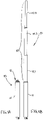
- the reference numeral 10 indicates in its entirety the light signaling device for the bow of a ship according to the invention.
- said device is illustrated without the light signaling means, which is supported fixed at the top thereof, and the related electric circuit supply and control means of the light signaling means itself.
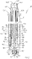
- Said device 10 comprises an outer cylindrical tubular liner 11, which is fixed with axis vertical with respect to the fixed structure of the ship (not illustrated), for example underneath a bridge.
- Said liner 11 comprises within a telescopic tubular rod 15, to support the light signaling means, and which in Fig. 1A is illustrated retracted and in Fig. 1B extended with respect to the liner 11 itself.
- said tubular liner for example made of stainless steel, has a lower cap 11.1 axially perforated and detachably attached to the liner itself.
- Said cap 11.1 supports, externally, a fixed box 11.2 containing therein, by means of bearing means 11.3, a helical worm wheel 12, coaxial and rotating freely with respect to said liner 11.
- a lower axial end of a first tubular lead screw 13 with trapezoidal outer thread is fixed coaxial, by means of a key, in said worm wheel 12 and extends axially along part of the height of said liner 11.
- a worm screw 12.1 with an essentially horizontal axis is meshed with respect to said worm wheel 12 and is kinematically connected with respect to an electrical gear-motor (not illustrated) that sets in rotation, when controlled, said worm screw 12.1 selectively in the two opposite directions of rotation, correspondingly setting in integral rotation said worm wheel 12 and said first lead screw 13.
- a first nut screw 14 for example made of bronze, is engaged with trapezoidal screw helical fit with said first lead screw 13 and supports a first coaxial fixed annular plate 14.1.
- Said first annular plate 14.1 supports a first fixed coaxial bush 14.2, proximal to said first lead screw 13, and a first fixed telescopic tubular section 15.1 of said telescopic tubular rod 15, distal from said first lead screw 13.
- Said first telescopic tubular section 15.1 is made, for example, of carbon.
- Said first bush 14.2 supports a second bush 17.1 coaxial and above, with an intermediate coaxial bearing support 17.2 that allows said second bush 17.1 to rotate independently with respect to said first bush 14.2.
- Said second bush 17.1 is integral in rotation with respect to said first lead screw 13 by means of a key 17.3.
- a pair of guide rings 19 are coaxially fixed on the outside surface of said second telescopic tubular section 15.2 and have respective external grooves 19.1 axially aligned with each other and engaged with a corresponding axial linear guide 19.2 attached to the inner surface of said first telescopic tubular section 15.1, for the entire length of the tubular section itself.
- said second telescopic tubular section 15.2 is translated, in the axial direction, integrally with said second nut screw 18, when said second tubular lead screw 17 is set in rotation integrally with said first lead screw 13 (integral with said second bush 17.1), while it is prevented from rotating with the second nut screw itself.
- Said third bush 18.2 supports a fourth bush 20.1 coaxial and above, with an intermediate coaxial bearing support 20.2 that allows said fourth bush 20.1 to rotate independently with respect to said third bush 18.2.
- Said fourth bush 20.1 is integral in rotation with respect to said second lead screw 17 by means of a key 20.3.
- a lower axial end of a third lead screw 20 is fixed, tubular, external and coaxial with respect to said second lead screw 17.
- a third nut screw 21 for example made of plastic material, is engaged with helical fit with said third tubular lead screw 20 and supports a fixed coaxial tubular sleeve 21.1.
- Said sleeve 21.1 supports, in turn, a third telescopic tubular section 15.3 of said telescopic tubular rod 15, coaxial with respect to said third lead screw 20.
- Said third telescopic tubular section 15.3 is made, for example, of carbon.
- the light signaling device for the bow of a ship 10 comprises, within the tubular outer liner 11, a telescopically extensible/retractable rod with three telescopic stages, each of which respectively includes:
- Said lead screws (13, 17, 20) are integral to one another in rotation and receive the motion from electrical gear-motor means by transmission means (12, 12.1) kinematically connected to one (13) of said lead screws.
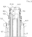
- said tubular outer liner 11 has, at the top thereof, an annular cover 11.4, through which the free upper end of said first telescopic section 15.1 is guided by means of corresponding annular sealing means.
- Said first telescopic section 15.1 has an outer flange 15.10 in the proximity of the upper end that, when said first telescopic section is retracted in the liner 11, rests on said cover 11.4.
- said first telescopic section 15.1 has, at the top thereof, an annular cover 15.11, through which the free upper end of said second telescopic section 15.2 is guided by means of corresponding annular sealing means.
- said second telescopic section 15.2 has, at the top thereof, an annular cover 15.21, through which the free upper end of said third telescopic section (15.3) is guided by means of corresponding annular sealing means.
- An annular cover 15.30 partially closes the free top of said third telescopic section (15.3) and has an axial through hole (15.31) aligned with the axial cavities of said three lead screws 13, 17 and 20. It can be noted that the fixed box 11 has an opening for housing a fixed sleeve 11.5, axially aligned with said hole 15.31 of the cover 15.30.
- the device 10 provides a free axial passage way, through the box 11 and said sleeve 11.5, the lead screws 13, 17, 20, the tubular telescopic sections 15.1, 15.2, 15.3 and said axial hole 15.31 of the cover 15.30, for example for the electrical cables, branching off to the light signaling means (which is fixed, for example, at the top of said third telescopic section 15.3) and related electric circuit supply and control means.
- An automatic winder/unwinder device of electrical cables can be provided in proximity of the fixed box 11, to facilitate the unwinding and rewinding operations of said electrical cables, during the extension/retraction of the telescopic support rod 15.
- the corresponding lead screws 14, 18, 21 translate linearly and automatically all by a same distance and determine a corresponding unthreading or extension of the respective tubular telescopic sections with one another and of the section 15.1 with respect to the tubular liner 11, with the same pitch, until reaching the operating arrangement, in which the telescopic rod-shaped vertical support 15 is fully extended, as illustrated in Fig. 1B .
- the electrical cables connected to the light signaling means and related electric circuit supply and control means are unwound automatically by said winder/unwinder and are arranged along the axial passage way through the box 11, the lead screws 13, 17, 20, the tubular telescopic sections 15.1, 15.2, 15.3 and the axial hole 15.31 of the cover 15.30.
- the light signaling device for the bow of a ship allows the objects set forth in the preamble to be achieved in a simple and effective way.
- the present invention provides a light signaling device for the bow of a ship with a simple, lightweight structure that does not require the use of hydraulic control means.
- the present invention consents the production of a signaling device as specified, which provides a direct and convenient passage way for the electrical cables branching off to the light signaling means and related electrical circuits.
Landscapes
- Chemical & Material Sciences (AREA)
- Engineering & Computer Science (AREA)
- Combustion & Propulsion (AREA)
- Mechanical Engineering (AREA)
- Ocean & Marine Engineering (AREA)
- Transmission Devices (AREA)
- Traffic Control Systems (AREA)
Claims (5)
- Leuchtsignalvorrichtung (10) für den Bug eines Schiffes, wobei die Leuchtsignalvorrichtung (10) eine rohrförmige äußere Verkleidung (11), eine Stützstange (15) mit mehreren teleskopisch ausfahrbaren/einziehbaren Stufen (15.1. 15.2, 15.3) umfasst,wobei eine erste der besagten teleskopisch ausfahrbaren/einziehbaren Stufen Folgendes umfasst:- eine erste Leitspindel (13),- eine erste Mutterschraube (14, 14.1), die mit der besagten Leitspindel (13) schraubenförmig gekoppelt ist,- einen entsprechenden ersten teleskopischen rohrförmigen Abschnitt (15.1), der koaxial und durch entsprechende Haltemittel in Bezug auf die besagte erste Mutterschraube (14) verbunden ist, und sich in axialer Richtung, fest verbunden mit der besagten Mutterschraube (14) verschiebt, wenn die besagte Leitspindel in Drehung versetzt wird, während sie mittels linearer Führungsmittel daran gehindert wird, sich mit der Mutterschraube zu drehen;wobei eine zweite der besagten teleskopisch ausfahrbaren/einziehbaren Stufen Folgendes umfasst:- eine zweite Leitspindel (17),- eine zweite Mutterschraube (18), die mit der besagten Leitspindel (17) schraubenförmig gekoppelt ist,- einen entsprechenden zweiten teleskopischen rohrförmigen Abschnitt (15.2) der koaxial und durch entsprechende Haltemittel in Bezug auf die besagte zweite Mutterschraube (18) verbunden ist,wobei sich der zweite rohrförmige teleskopische Abschnitt (15.2) in axialer Richtung, fest verbunden mit der besagten zweiten Mutterschraube (18) verschiebt, wenn die besagte zweite Leitspindel (17) in Drehung versetzt wird, während sie mittels linearer Führungsmittel daran gehindert wird, sich mit der zweiten Mutterschraube zu drehen;wobei die besagte erste Leitspindel (13) die Bewegung von elektrischen Getriebemotormitteln mittels Übertragungsmitteln (12, 12.1) ableitet, die mit der besagten ersten Leitspindel (13) kinematisch verbunden sind, undwobei die besagte erste (13) und die zweite (17) Leitspindel rohrförmig, koaxial und mit einem Außengewinde versehen sind, wobei die Leuchtsignalvorrichtung (10) weiterhin Folgendes umfasst:- erste Hülsenmittel (14.2), die fest von der besagten ersten Mutterschraube (14, 14.1) getragen werden,- erste mittlere Lagerhaltemittel (17.2) die in koaxialer Anordnung von den besagten ersten Hülsenmitteln (14.2) getragen werden, und- zweite Hülsenmittel (17.1), die in koaxialer Anordnung von den besagten ersten mittleren Lagerhaltemittel (17.2) getragen werden, wobei die besagten zweiten Hülsenmittel (17.1) bei Drehung in Bezug auf die besagte erste Leitspindel (13) mittels eines Keils (17.3) fest verbunden sind, wobei die Außenfläche der ersten Leitspindel (13) eine sich über ihre Länge erstreckende Nut aufweist, in die der besagte Keil (17.3) hineinragt,
wobei ein unteres axiales Ende der besagten zweiten Leitspindel (17) in den besagten zweiten Hülsenmitteln (17.1), außerhalb und koaxial in Bezug auf die besagte erste Leitspindel (13), befestigt ist. - Leuchtsignalvorrichtung (10) gemäß Anspruch 1,wobeiein Drittel der besagten teleskopisch ausfahrbaren/einziehbaren Stufen Folgendes einschließt:- eine dritte Leitspindel (20),- eine dritte Mutterschraube (21), die mit der besagten dritten Leitspindel (20) schraubenförmig gekoppelt ist,- einen entsprechenden dritten teleskopischen rohrförmigen Abschnitt (15.3) der koaxial und durch entsprechende Haltemittel in Bezug auf die besagte dritte Mutterschraube (21) verbunden ist, wobei sich der dritte teleskopische rohrförmige Abschnitt (15.3) in axialer Richtung, fest verbunden mit der besagten dritten Mutterschraube (21), verschiebt, wenn die besagte dritte Leitspindel (20) in Drehung versetzt wird, wobei der dritte teleskopische rohrförmige Abschnitt (15.3) und die dritte Mutterschraube (21) mittels linearer Führungsmittel daran gehindert werden, sich zu drehen;- dritte Hülsenmittel (18.2), die fest von der besagten zweiten Mutterschraube (18) getragen werden, zweite mittlere Lagerhaltemittel (20.2), die in koaxialer Anordnung von den besagten dritten Hülsenmitteln (18.2) getragen werden,- vierte Hülsenmittel (20.1), die in koaxialer Anordnung von den besagten zweiten mittleren Lagerhaltemittel (20.2) getragen werden, wobei die besagten vierten Hülsenmittel (20.1) bei Drehung in Bezug auf die besagte zweite Leitspindel (17) mittels eines Keils (20.3) fest verbunden sind, wobei die Außenfläche der zweiten Leitspindel (17) eine sich über ihre Länge erstreckende Nut aufweist, in die der besagte Keil (20.3) hineinragt, und- wobei die besagte dritte Leitspindel (20) rohrförmig und mit einem Außengewinde versehen ist, wobei ein unteres axiales Ende der besagten dritten Leitspindel (20) an den besagten vierten Hülsenmitteln (20.1), außerhalb und koaxial in Bezug auf die besagte zweite Leitspindel (17), befestigt und mit der besagten dritten Leitspindel (21) schraubenförmig gekoppelt ist.
- Leuchtsignalvorrichtung (10) gemäß Anspruch 1, wobei die besagten linearen Führungsmittel (16, 19, 22; 16.1, 19.1; 16.2, 19.2, 22.2) Führungsringe (16, 19, 22) umfassen, die koaxial an der Außenfläche eines jeweiligen teleskopischen rohrförmigen Abschnitts (15.1, 15.2, 15.3) befestigt sind und jeweilige äußere axiale Nuten (16.1, 19.1) aufweisen, die zueinander ausgerichtet sind und mit entsprechenden axialen linearen Führungsmitteln (16.2, 19.2, 22.2) in Anspruch genommen werden, die an der Innenfläche der besagten Verkleidung (11), bzw. des angrenzenden teleskopischen rohrförmigen Abschnitts (15.1, 15.2) befestigt sind.
- Leuchtsignalvorrichtung (10) gemäß einem oder mehreren der Ansprüche von 2 bis 3, wobei:- die besagte äußere rohrförmige Verkleidung (11) an ihrem oberen Ende eine ringförmige Abdeckung (11.4) aufweist, durch die mittels entsprechender ringförmiger Dichtungsmittel das freie obere Ende des besagten ersten teleskopischen Abschnitts (15.1) geführt wird;- der besagte erste teleskopische Abschnitt (15.1) an seinem oberen Ende eine ringförmige Abdeckung (15.11) trägt, durch die mittels entsprechender ringförmiger Dichtungsmittel das freie obere Ende des besagten zweiten teleskopischen Abschnitts (15.2) geführt wird;- der besagte zweite teleskopische Abschnitt (15.2) an seinem oberen Ende eine ringförmige Abdeckung (15.21) trägt, durch die mittels entsprechender ringförmiger Dichtungen das freie obere Ende des besagten dritten teleskopischen Abschnitts (15.3) geführt wird;- eine ringförmige Abdeckung (15.30) teilweise das freie obere Ende des besagten dritten teleskopischen Abschnitts (15.3) verschließt und ein axiales Durchgangsloch (15.31) aufweist, das mit den axialen Aussparungen der besagten Leitspindeln (13, 17, 20) ausgerichtet ist,
und wobei die besagte Vorrichtung (10) einen freien axialen Durchgang umfasst, der durch die besagten Leitspindeln (13, 17, 20), die besagten teleskopischen rohrförmigen Abschnitte (15.1, 15.2, 15.3) und das besagte axiale Loch (15.31) der Abdeckung (15.30) für elektrische Kabel vorgesehen ist, die zu dem Leuchtsignalmittel und den entsprechenden Versorgungs- und Steuerschaltungsmitteln abgehen. - Leuchtsignalvorrichtung (10) gemäß Anspruch 4, wobei der besagte erste teleskopische Abschnitt (15.1) in der Nähe des oberen Endes einen äußeren Flansch (15.10) aufweist.
Applications Claiming Priority (1)
| Application Number | Priority Date | Filing Date | Title |
|---|---|---|---|
| IT102016000114853A IT201600114853A1 (it) | 2016-11-14 | 2016-11-14 | Dispositivo di segnalazione luminosa per prua di nave |
Publications (2)
| Publication Number | Publication Date |
|---|---|
| EP3321164A1 EP3321164A1 (de) | 2018-05-16 |
| EP3321164B1 true EP3321164B1 (de) | 2022-06-29 |
Family
ID=58670132
Family Applications (1)
| Application Number | Title | Priority Date | Filing Date |
|---|---|---|---|
| EP17001823.8A Active EP3321164B1 (de) | 2016-11-14 | 2017-11-08 | Leuchtsignalisierungsvorrichtung für schiffsbug |
Country Status (2)
| Country | Link |
|---|---|
| EP (1) | EP3321164B1 (de) |
| IT (1) | IT201600114853A1 (de) |
Families Citing this family (2)
| Publication number | Priority date | Publication date | Assignee | Title |
|---|---|---|---|---|
| IT202000014479A1 (it) * | 2020-06-17 | 2021-12-17 | Ams Advanced Mech Solutions | Giunto di collegamento per supporto telescopico e supporto telescopico comprendente tale giunto di collegamento |
| IT202300013737A1 (it) | 2023-06-30 | 2024-12-30 | Setec | Dispositivo di segnalazione luminosa di prua di nave |
Family Cites Families (4)
| Publication number | Priority date | Publication date | Assignee | Title |
|---|---|---|---|---|
| US1212968A (en) * | 1916-02-28 | 1917-01-16 | Orin P Lively | Telescopic mast. |
| DE202011050508U1 (de) * | 2011-06-21 | 2011-08-24 | Federal Signal Vama, S.A. | Teleskopmast für Vorrang-Signalisierung |
| US20130039081A1 (en) * | 2011-08-10 | 2013-02-14 | R & D Shed, L.L.C. | Retractable boat light |
| FR2987820B1 (fr) * | 2012-03-08 | 2015-05-22 | Arnaud Maillard | Dispositif pour la signalisation d'un bateau au mouillage de jour, selon la reglementation maritime en vigueur |
-
2016
- 2016-11-14 IT IT102016000114853A patent/IT201600114853A1/it unknown
-
2017
- 2017-11-08 EP EP17001823.8A patent/EP3321164B1/de active Active
Also Published As
| Publication number | Publication date |
|---|---|
| IT201600114853A1 (it) | 2018-05-14 |
| EP3321164A1 (de) | 2018-05-16 |
Similar Documents
| Publication | Publication Date | Title |
|---|---|---|
| EP3321164B1 (de) | Leuchtsignalisierungsvorrichtung für schiffsbug | |
| EP2641502B1 (de) | Linearaktuator und höhenverstellbarer Tisch | |
| JP6576464B2 (ja) | ねじ駆動機構を備える4段テレスコープ式アクチュエーター | |
| WO2006098739A3 (en) | Heavy duty field mast | |
| US20110174101A1 (en) | Height-adjustable actuation device | |
| US8944467B1 (en) | Automated RV landing gear | |
| ATE522766T1 (de) | Beweglicher mehrdirektionaler leuchtenständer | |
| SE533935C2 (sv) | Gyratorisk kross | |
| US20200085185A1 (en) | Telescopic column with internal cable | |
| US10265706B2 (en) | Scraper device with blow nozzle and telescopic gas pipes for centrifuge | |
| CN207668541U (zh) | 一种机械涨轴 | |
| DE3428545C2 (de) | ||
| EP3614884B1 (de) | Teleskopsäule für höhenverstellbare möbel | |
| CN209797162U (zh) | 通信工程用通信线缆收放装置的夹持结构 | |
| CN103358274B (zh) | 一种油封装配专用工具 | |
| CN208010904U (zh) | 一种推杆螺母螺杆固定润滑机构 | |
| CN104917084A (zh) | 带照明装置的绝缘操作杆 | |
| NO20064571L (no) | Regulering av teleskopisk bevegelige element | |
| EP4488573B1 (de) | Signallichtanlage für schiffsbug | |
| US1868478A (en) | Lifting jack | |
| US20240245210A1 (en) | Telescopic column with stabilizing device | |
| US2326443A (en) | Automobile radio antenna | |
| RU2012141734A (ru) | Роторный подложкодержатель | |
| US3069180A (en) | Seal construction | |
| EP3821137B1 (de) | Kolben-zylinder-einheit für eine arbeitsmaschine |
Legal Events
| Date | Code | Title | Description |
|---|---|---|---|
| PUAI | Public reference made under article 153(3) epc to a published international application that has entered the european phase |
Free format text: ORIGINAL CODE: 0009012 |
|
| STAA | Information on the status of an ep patent application or granted ep patent |
Free format text: STATUS: THE APPLICATION HAS BEEN PUBLISHED |
|
| AK | Designated contracting states |
Kind code of ref document: A1 Designated state(s): AL AT BE BG CH CY CZ DE DK EE ES FI FR GB GR HR HU IE IS IT LI LT LU LV MC MK MT NL NO PL PT RO RS SE SI SK SM TR |
|
| AX | Request for extension of the european patent |
Extension state: BA ME |
|
| STAA | Information on the status of an ep patent application or granted ep patent |
Free format text: STATUS: REQUEST FOR EXAMINATION WAS MADE |
|
| 17P | Request for examination filed |
Effective date: 20181112 |
|
| RBV | Designated contracting states (corrected) |
Designated state(s): AL AT BE BG CH CY CZ DE DK EE ES FI FR GB GR HR HU IE IS IT LI LT LU LV MC MK MT NL NO PL PT RO RS SE SI SK SM TR |
|
| STAA | Information on the status of an ep patent application or granted ep patent |
Free format text: STATUS: EXAMINATION IS IN PROGRESS |
|
| 17Q | First examination report despatched |
Effective date: 20201021 |
|
| GRAP | Despatch of communication of intention to grant a patent |
Free format text: ORIGINAL CODE: EPIDOSNIGR1 |
|
| STAA | Information on the status of an ep patent application or granted ep patent |
Free format text: STATUS: GRANT OF PATENT IS INTENDED |
|
| INTG | Intention to grant announced |
Effective date: 20211110 |
|
| GRAS | Grant fee paid |
Free format text: ORIGINAL CODE: EPIDOSNIGR3 |
|
| GRAA | (expected) grant |
Free format text: ORIGINAL CODE: 0009210 |
|
| STAA | Information on the status of an ep patent application or granted ep patent |
Free format text: STATUS: THE PATENT HAS BEEN GRANTED |
|
| AK | Designated contracting states |
Kind code of ref document: B1 Designated state(s): AL AT BE BG CH CY CZ DE DK EE ES FI FR GB GR HR HU IE IS IT LI LT LU LV MC MK MT NL NO PL PT RO RS SE SI SK SM TR |
|
| REG | Reference to a national code |
Ref country code: CH Ref legal event code: EP |
|
| REG | Reference to a national code |
Ref country code: AT Ref legal event code: REF Ref document number: 1501190 Country of ref document: AT Kind code of ref document: T Effective date: 20220715 |
|
| REG | Reference to a national code |
Ref country code: IE Ref legal event code: FG4D |
|
| REG | Reference to a national code |
Ref country code: DE Ref legal event code: R096 Ref document number: 602017058922 Country of ref document: DE |
|
| REG | Reference to a national code |
Ref country code: NL Ref legal event code: FP |
|
| REG | Reference to a national code |
Ref country code: LT Ref legal event code: MG9D |
|
| PG25 | Lapsed in a contracting state [announced via postgrant information from national office to epo] |
Ref country code: SE Free format text: LAPSE BECAUSE OF FAILURE TO SUBMIT A TRANSLATION OF THE DESCRIPTION OR TO PAY THE FEE WITHIN THE PRESCRIBED TIME-LIMIT Effective date: 20220629 Ref country code: NO Free format text: LAPSE BECAUSE OF FAILURE TO SUBMIT A TRANSLATION OF THE DESCRIPTION OR TO PAY THE FEE WITHIN THE PRESCRIBED TIME-LIMIT Effective date: 20220929 Ref country code: LT Free format text: LAPSE BECAUSE OF FAILURE TO SUBMIT A TRANSLATION OF THE DESCRIPTION OR TO PAY THE FEE WITHIN THE PRESCRIBED TIME-LIMIT Effective date: 20220629 Ref country code: HR Free format text: LAPSE BECAUSE OF FAILURE TO SUBMIT A TRANSLATION OF THE DESCRIPTION OR TO PAY THE FEE WITHIN THE PRESCRIBED TIME-LIMIT Effective date: 20220629 Ref country code: GR Free format text: LAPSE BECAUSE OF FAILURE TO SUBMIT A TRANSLATION OF THE DESCRIPTION OR TO PAY THE FEE WITHIN THE PRESCRIBED TIME-LIMIT Effective date: 20220930 Ref country code: FI Free format text: LAPSE BECAUSE OF FAILURE TO SUBMIT A TRANSLATION OF THE DESCRIPTION OR TO PAY THE FEE WITHIN THE PRESCRIBED TIME-LIMIT Effective date: 20220629 Ref country code: BG Free format text: LAPSE BECAUSE OF FAILURE TO SUBMIT A TRANSLATION OF THE DESCRIPTION OR TO PAY THE FEE WITHIN THE PRESCRIBED TIME-LIMIT Effective date: 20220929 |
|
| REG | Reference to a national code |
Ref country code: AT Ref legal event code: MK05 Ref document number: 1501190 Country of ref document: AT Kind code of ref document: T Effective date: 20220629 |
|
| PG25 | Lapsed in a contracting state [announced via postgrant information from national office to epo] |
Ref country code: RS Free format text: LAPSE BECAUSE OF FAILURE TO SUBMIT A TRANSLATION OF THE DESCRIPTION OR TO PAY THE FEE WITHIN THE PRESCRIBED TIME-LIMIT Effective date: 20220629 Ref country code: LV Free format text: LAPSE BECAUSE OF FAILURE TO SUBMIT A TRANSLATION OF THE DESCRIPTION OR TO PAY THE FEE WITHIN THE PRESCRIBED TIME-LIMIT Effective date: 20220629 |
|
| PG25 | Lapsed in a contracting state [announced via postgrant information from national office to epo] |
Ref country code: SM Free format text: LAPSE BECAUSE OF FAILURE TO SUBMIT A TRANSLATION OF THE DESCRIPTION OR TO PAY THE FEE WITHIN THE PRESCRIBED TIME-LIMIT Effective date: 20220629 Ref country code: SK Free format text: LAPSE BECAUSE OF FAILURE TO SUBMIT A TRANSLATION OF THE DESCRIPTION OR TO PAY THE FEE WITHIN THE PRESCRIBED TIME-LIMIT Effective date: 20220629 Ref country code: RO Free format text: LAPSE BECAUSE OF FAILURE TO SUBMIT A TRANSLATION OF THE DESCRIPTION OR TO PAY THE FEE WITHIN THE PRESCRIBED TIME-LIMIT Effective date: 20220629 Ref country code: PT Free format text: LAPSE BECAUSE OF FAILURE TO SUBMIT A TRANSLATION OF THE DESCRIPTION OR TO PAY THE FEE WITHIN THE PRESCRIBED TIME-LIMIT Effective date: 20221031 Ref country code: ES Free format text: LAPSE BECAUSE OF FAILURE TO SUBMIT A TRANSLATION OF THE DESCRIPTION OR TO PAY THE FEE WITHIN THE PRESCRIBED TIME-LIMIT Effective date: 20220629 Ref country code: EE Free format text: LAPSE BECAUSE OF FAILURE TO SUBMIT A TRANSLATION OF THE DESCRIPTION OR TO PAY THE FEE WITHIN THE PRESCRIBED TIME-LIMIT Effective date: 20220629 Ref country code: AT Free format text: LAPSE BECAUSE OF FAILURE TO SUBMIT A TRANSLATION OF THE DESCRIPTION OR TO PAY THE FEE WITHIN THE PRESCRIBED TIME-LIMIT Effective date: 20220629 |
|
| PG25 | Lapsed in a contracting state [announced via postgrant information from national office to epo] |
Ref country code: PL Free format text: LAPSE BECAUSE OF FAILURE TO SUBMIT A TRANSLATION OF THE DESCRIPTION OR TO PAY THE FEE WITHIN THE PRESCRIBED TIME-LIMIT Effective date: 20220629 Ref country code: IS Free format text: LAPSE BECAUSE OF FAILURE TO SUBMIT A TRANSLATION OF THE DESCRIPTION OR TO PAY THE FEE WITHIN THE PRESCRIBED TIME-LIMIT Effective date: 20221029 |
|
| REG | Reference to a national code |
Ref country code: DE Ref legal event code: R097 Ref document number: 602017058922 Country of ref document: DE |
|
| PG25 | Lapsed in a contracting state [announced via postgrant information from national office to epo] |
Ref country code: AL Free format text: LAPSE BECAUSE OF FAILURE TO SUBMIT A TRANSLATION OF THE DESCRIPTION OR TO PAY THE FEE WITHIN THE PRESCRIBED TIME-LIMIT Effective date: 20220629 |
|
| PG25 | Lapsed in a contracting state [announced via postgrant information from national office to epo] |
Ref country code: DK Free format text: LAPSE BECAUSE OF FAILURE TO SUBMIT A TRANSLATION OF THE DESCRIPTION OR TO PAY THE FEE WITHIN THE PRESCRIBED TIME-LIMIT Effective date: 20220629 Ref country code: CZ Free format text: LAPSE BECAUSE OF FAILURE TO SUBMIT A TRANSLATION OF THE DESCRIPTION OR TO PAY THE FEE WITHIN THE PRESCRIBED TIME-LIMIT Effective date: 20220629 |
|
| PLBE | No opposition filed within time limit |
Free format text: ORIGINAL CODE: 0009261 |
|
| STAA | Information on the status of an ep patent application or granted ep patent |
Free format text: STATUS: NO OPPOSITION FILED WITHIN TIME LIMIT |
|
| 26N | No opposition filed |
Effective date: 20230330 |
|
| PG25 | Lapsed in a contracting state [announced via postgrant information from national office to epo] |
Ref country code: MC Free format text: LAPSE BECAUSE OF FAILURE TO SUBMIT A TRANSLATION OF THE DESCRIPTION OR TO PAY THE FEE WITHIN THE PRESCRIBED TIME-LIMIT Effective date: 20220629 |
|
| REG | Reference to a national code |
Ref country code: CH Ref legal event code: PL |
|
| GBPC | Gb: european patent ceased through non-payment of renewal fee |
Effective date: 20221108 |
|
| REG | Reference to a national code |
Ref country code: BE Ref legal event code: MM Effective date: 20221130 |
|
| PG25 | Lapsed in a contracting state [announced via postgrant information from national office to epo] |
Ref country code: LI Free format text: LAPSE BECAUSE OF NON-PAYMENT OF DUE FEES Effective date: 20221130 Ref country code: CH Free format text: LAPSE BECAUSE OF NON-PAYMENT OF DUE FEES Effective date: 20221130 |
|
| PG25 | Lapsed in a contracting state [announced via postgrant information from national office to epo] |
Ref country code: SI Free format text: LAPSE BECAUSE OF FAILURE TO SUBMIT A TRANSLATION OF THE DESCRIPTION OR TO PAY THE FEE WITHIN THE PRESCRIBED TIME-LIMIT Effective date: 20220629 Ref country code: LU Free format text: LAPSE BECAUSE OF NON-PAYMENT OF DUE FEES Effective date: 20221108 |
|
| PG25 | Lapsed in a contracting state [announced via postgrant information from national office to epo] |
Ref country code: IE Free format text: LAPSE BECAUSE OF NON-PAYMENT OF DUE FEES Effective date: 20221108 Ref country code: GB Free format text: LAPSE BECAUSE OF NON-PAYMENT OF DUE FEES Effective date: 20221108 |
|
| PG25 | Lapsed in a contracting state [announced via postgrant information from national office to epo] |
Ref country code: BE Free format text: LAPSE BECAUSE OF NON-PAYMENT OF DUE FEES Effective date: 20221130 |
|
| PG25 | Lapsed in a contracting state [announced via postgrant information from national office to epo] |
Ref country code: IT Free format text: LAPSE BECAUSE OF FAILURE TO SUBMIT A TRANSLATION OF THE DESCRIPTION OR TO PAY THE FEE WITHIN THE PRESCRIBED TIME-LIMIT Effective date: 20220629 |
|
| PG25 | Lapsed in a contracting state [announced via postgrant information from national office to epo] |
Ref country code: HU Free format text: LAPSE BECAUSE OF FAILURE TO SUBMIT A TRANSLATION OF THE DESCRIPTION OR TO PAY THE FEE WITHIN THE PRESCRIBED TIME-LIMIT; INVALID AB INITIO Effective date: 20171108 |
|
| PG25 | Lapsed in a contracting state [announced via postgrant information from national office to epo] |
Ref country code: CY Free format text: LAPSE BECAUSE OF FAILURE TO SUBMIT A TRANSLATION OF THE DESCRIPTION OR TO PAY THE FEE WITHIN THE PRESCRIBED TIME-LIMIT Effective date: 20220629 |
|
| PG25 | Lapsed in a contracting state [announced via postgrant information from national office to epo] |
Ref country code: MK Free format text: LAPSE BECAUSE OF FAILURE TO SUBMIT A TRANSLATION OF THE DESCRIPTION OR TO PAY THE FEE WITHIN THE PRESCRIBED TIME-LIMIT Effective date: 20220629 |
|
| PG25 | Lapsed in a contracting state [announced via postgrant information from national office to epo] |
Ref country code: MT Free format text: LAPSE BECAUSE OF FAILURE TO SUBMIT A TRANSLATION OF THE DESCRIPTION OR TO PAY THE FEE WITHIN THE PRESCRIBED TIME-LIMIT Effective date: 20220629 |
|
| PG25 | Lapsed in a contracting state [announced via postgrant information from national office to epo] |
Ref country code: BG Free format text: LAPSE BECAUSE OF FAILURE TO SUBMIT A TRANSLATION OF THE DESCRIPTION OR TO PAY THE FEE WITHIN THE PRESCRIBED TIME-LIMIT Effective date: 20220629 |
|
| PG25 | Lapsed in a contracting state [announced via postgrant information from national office to epo] |
Ref country code: BG Free format text: LAPSE BECAUSE OF FAILURE TO SUBMIT A TRANSLATION OF THE DESCRIPTION OR TO PAY THE FEE WITHIN THE PRESCRIBED TIME-LIMIT Effective date: 20220629 |
|
| PGFP | Annual fee paid to national office [announced via postgrant information from national office to epo] |
Ref country code: NL Payment date: 20251128 Year of fee payment: 9 |
|
| PGFP | Annual fee paid to national office [announced via postgrant information from national office to epo] |
Ref country code: FR Payment date: 20251128 Year of fee payment: 9 |
|
| PGFP | Annual fee paid to national office [announced via postgrant information from national office to epo] |
Ref country code: TR Payment date: 20251204 Year of fee payment: 9 |
|
| PGFP | Annual fee paid to national office [announced via postgrant information from national office to epo] |
Ref country code: DE Payment date: 20251231 Year of fee payment: 9 |