EP3320788B1 - Machine for producing rod-shaped products for the tobacco processing industry and related forming set - Google Patents
Machine for producing rod-shaped products for the tobacco processing industry and related forming set Download PDFInfo
- Publication number
- EP3320788B1 EP3320788B1 EP17200584.5A EP17200584A EP3320788B1 EP 3320788 B1 EP3320788 B1 EP 3320788B1 EP 17200584 A EP17200584 A EP 17200584A EP 3320788 B1 EP3320788 B1 EP 3320788B1
- Authority
- EP
- European Patent Office
- Prior art keywords
- garniture
- format
- base
- shaping
- components
- Prior art date
- Legal status (The legal status is an assumption and is not a legal conclusion. Google has not performed a legal analysis and makes no representation as to the accuracy of the status listed.)
- Active
Links
- 241000208125 Nicotiana Species 0.000 title claims description 8
- 235000002637 Nicotiana tabacum Nutrition 0.000 title claims description 8
- 238000007493 shaping process Methods 0.000 claims description 58
- 238000004519 manufacturing process Methods 0.000 claims description 35
- 239000000110 cooling liquid Substances 0.000 claims description 33
- 239000011248 coating agent Substances 0.000 claims description 21
- 238000000576 coating method Methods 0.000 claims description 21
- XAGFODPZIPBFFR-UHFFFAOYSA-N aluminium Chemical compound [Al] XAGFODPZIPBFFR-UHFFFAOYSA-N 0.000 claims description 7
- 229910052782 aluminium Inorganic materials 0.000 claims description 7
- 239000004696 Poly ether ether ketone Substances 0.000 claims description 6
- 229920002530 polyetherether ketone Polymers 0.000 claims description 6
- 230000000284 resting effect Effects 0.000 claims description 4
- 239000000919 ceramic Substances 0.000 claims description 3
- 230000002687 intercalation Effects 0.000 claims 1
- 238000009830 intercalation Methods 0.000 claims 1
- 239000000463 material Substances 0.000 description 10
- 230000017525 heat dissipation Effects 0.000 description 8
- 238000011161 development Methods 0.000 description 5
- 230000018109 developmental process Effects 0.000 description 5
- 238000001816 cooling Methods 0.000 description 4
- 238000005299 abrasion Methods 0.000 description 3
- 230000000295 complement effect Effects 0.000 description 3
- 230000003247 decreasing effect Effects 0.000 description 2
- 230000001419 dependent effect Effects 0.000 description 2
- 238000010894 electron beam technology Methods 0.000 description 2
- 238000000034 method Methods 0.000 description 2
- 238000003801 milling Methods 0.000 description 2
- 238000000926 separation method Methods 0.000 description 2
- 238000004026 adhesive bonding Methods 0.000 description 1
- 230000009286 beneficial effect Effects 0.000 description 1
- 239000002131 composite material Substances 0.000 description 1
- 239000000835 fiber Substances 0.000 description 1
- 239000003292 glue Substances 0.000 description 1
- 239000007788 liquid Substances 0.000 description 1
- 239000004848 polyfunctional curative Substances 0.000 description 1
- 239000007787 solid Substances 0.000 description 1
- 238000004381 surface treatment Methods 0.000 description 1
Images

Classifications
-
- A—HUMAN NECESSITIES
- A24—TOBACCO; CIGARS; CIGARETTES; SIMULATED SMOKING DEVICES; SMOKERS' REQUISITES
- A24C—MACHINES FOR MAKING CIGARS OR CIGARETTES
- A24C5/00—Making cigarettes; Making tipping materials for, or attaching filters or mouthpieces to, cigars or cigarettes
- A24C5/14—Machines of the continuous-rod type
- A24C5/18—Forming the rod
- A24C5/1807—Forming the rod with compressing means, e.g. garniture
Definitions
- the invention relates to a rod manufacturing machine for manufacturing products of the tobacco processing industry with the features of the preamble of claim 1 and an associated format set with the features of the preamble of claim 6.
- an endless rod of non-shape-fixed tobacco or filter material is generally placed on a wrapping strip that is moved in the longitudinal direction and is fixed in shape to form a solid strand during the transport movement of the wrapping strip by folding and gluing the side edges of the wrapping strip.
- tubes are also used, which are made from a strip and can additionally be provided with filter material on the outside.
- the tubes can also be fixed in shape on the outside, similar to conventional filters, by means of a covering strip.
- the strip is folded over from a flat orientation into the tube shape and glued at the side edges.
- the strand is formed by an endless tube which is shaped in the strand manufacturing machine and glued to the side edges to fix the shape.
- the format tape In turn rests on a format base which is formed from one or more format lower parts and is provided with a groove which has a depth increasing in the direction of the transport movement with a decreasing radius of curvature. Due to the provided in the format reason Trough with the decreasing radius of curvature, the format tape lying thereon with the wrapping strip or strip lying thereon is turned up with the side edges on the side of the strand during the transport movement and shaped into a semicircular cross-section in the lower half.
- side edges After the side edges have been turned up, they are laid around the strand or formed into a tube by means of further format parts, or cover parts, which close the channel on the top to form a shaping channel, and with one another by means of a glue track arranged on one of the side edges in a previous work step glued.
- side edges of the wrapping strip or the strip is understood in the context of this application to mean the lateral edge portions of the wrapping strip or the strip which are wrapped around the strand to wrap it or, starting from the U-shape, are wrapped further into the ring shape.
- the format base and the format parts are also referred to together as format fittings and each have a shaping surface, which complement one another to form an overall shaping surface and are designed or dimensioned for the production of a strand of a predetermined geometry. If a strand with a different geometry or a different diameter is to be produced, the format set must be exchanged for another format set with correspondingly adapted shaping surfaces.
- Such a strand production machine with such a format clothing is, for example, from DE 36 24 098 A1 known.
- a guide part on a machine in the tobacco processing industry with a sliding surface for a conveyor belt or a strip-shaped wrapping material is shown in DE 25 31 488 A1 disclosed.
- US 2004/118416 A1 discloses a format clothing that can be treated to reduce friction in an entrance area.
- the wrapping strip of the finished products that holds the strand together should be as free from creases as possible and without markings. For this it is necessary to lay the side edges of the wrapping strip around the strand as neatly as possible after turning it up at the side, and finally to lay them on top of one another before they are glued together.
- the shaping surfaces of the format parts are therefore subject to particularly high requirements.
- the high requirements to be met for the dimensional accuracy of the shaping surfaces of a few hundredths of a millimeter are a particular problem.
- the shaping surfaces are subject to increased wear due to the format tape guided on them. For this reason, the format parts are subjected to a special hardening process in a hardening furnace, which in turn is disadvantageous for any subsequent reworking of the other surfaces of the format parts, since this considerably increases the processing times of the reworking.
- the friction between the format tape and the shaping surfaces of the format parts should be as low as possible so that the format parts heat up as little as possible in the area of the shaping surfaces. It cannot be prevented that the format parts nevertheless heat up slightly and therefore have to be cooled.
- the format parts are cooled by a liquid circuit with several flow channels arranged in the format parts through which a cooling liquid flows. The flow channels are drilled in a separate operation, the arrangement of the flow channels presupposing a certain minimum wall thickness of the format parts and / or the format base in the area of the flow channels.
- the invention is based on the object of providing a generic strand production machine and a format clothing which can be produced more cost-effectively.
- the strand production machine according to the invention or the proposed format clothing it should be possible to produce a strand with improved dimensional accuracy.
- the format base and / or at least one of the format parts and / or a counter surface of the strand production machine has a recess in a section which, together with an opposite surface of the format base and / or the format part and / or a counter surface of the strand production machine, has one of forms a flow channel through which a cooling liquid flows.
- the flow channel is thus formed, instead of a bore, through a recess, which is much easier to produce, on one of the parts and an opposite surface of the respective opposite part by assembling the parts.
- the recess is arranged in one of the surfaces of the format base and / or of the format part which has the lower hardness.
- the advantage according to the invention of the simplified machinability of the surface made possible due to the lower hardness is exploited, in that the depression is subsequently incorporated into the easier-to-machine surface, for example by a milling process.
- the surface of the format clothing, past which the cooling liquid flows can be placed closer to the shaping surface to be cooled so that the heat dissipation from the shaping surface can be increased.
- the shaping surface can be cooled to a lower temperature, or, conversely, it is possible to reduce the volume flow of the cooling liquid required to cool the shaping surface to a predetermined temperature level.
- the recess can be designed as a wide groove, which can be adapted in shape and in course to the shape of the shaping surface. It is further proposed that at least one rib aligned in the longitudinal extension of the flow channel is provided in the flow channel. The surface available for heat dissipation and thus the heat dissipation itself can be further enlarged by the rib. Since the rib is aligned in the longitudinal direction, that is to say in the direction of flow of the cooling liquid, vortices or dead spaces are prevented from forming on or behind the rib, which could interfere with the dissipation of heat.
- the flow path through which the cooling liquid flows is lengthened, so that the cooling liquid can absorb and transport away more heat.
- the rib forms a dividing wall which divides the flow channel into two partial flow channels through which the cooling liquid flows through one or more deflections in different directions.
- the format base can preferably be designed in one piece.
- the format base with the shaping surface provided on it can thus be manufactured and assembled in one piece as one part, as a result of which assembly times and manufacturing costs can be reduced.
- the manufacturing costs are reduced in particular because the previously required high manufacturing and assembly accuracy of the previously used individual parts of the format base is no longer necessary.
- the individual parts used up to now they first had to be manufactured with great accuracy and then mounted on a very precise counter surface of the strand manufacturing machine so that the finally assembled shaping surface of the format base corresponds to the required requirements. If the requirements were not met, either the counter surface or the individual parts of the format base had to be laboriously reworked.
- the shaping surface of the format base is now realized on a single part and can be produced on this with a correspondingly precise shape and individually. This eliminates the possible source of error of a form deviation due to the previously existing joints between the individual parts. As a result of the resulting improved quality of the shaping surface, a strand with an improved surface quality can be realized with a simultaneous reduction in wear on the shaping surface. Furthermore, the proposed solution can shorten the required retooling time of the strand manufacturing machine when changing formats.
- the higher hardness of the shaping surface is achieved by local surface hardening.
- a local Surface hardening the shaping surface can be processed in a targeted manner and the desired hardness can be achieved, while the hardness of the components in the remaining surfaces is specifically not increased for the purpose of simpler subsequent processing.
- the hardness can only be increased in specifically selected areas of the surfaces or sections of the shaping surface without the hardness in the core of the component or in the remaining surfaces being changed or increased.
- Such a local surface treatment with a correspondingly high surface hardness to be achieved can be, for example, electron beam hardening.
- the overflow point enables the cooling liquid to be deflected from one partial flow channel into another partial flow channel, while the flow separation prevents mixing of the cooling liquid or enables the cooling liquid to flow in different directions in the first place.
- the cooling liquid can be guided in such a way that it is deflected between the partial flow channels by an angle of 180 degrees.
- the proposed solution allows the cooling liquid to flow in the two partial flow channels very easily through an elongated depression with a central rib running parallel to the longitudinal extension be realized.
- the flow path to be traversed can be increased to the maximum in that the cooling liquid ideally flows through the flow channel twice along its length.
- the overflow point is preferably arranged at one of the ends or in one of the ends of the rib. This advantage can be further increased by an increased number of ribs and a multiple deflection or enlarged cooling surface caused thereby.
- the format base and / or at least one of the format parts have a coating.
- the surface properties of the format base and / or the format parts can be specifically changed and improved in specifically selected areas in accordance with the properties of the coating. For example, it is possible to improve the sliding properties and / or increase the abrasion resistance.
- the proposed increase in the hardener can be achieved by the coating by choosing a coating material with a higher hardness.
- the coating is formed by a plasma ceramic and, according to a further preferred further development, inclusions of polyether ether ketone (PEEK) are provided in the coating.
- PEEK polyether ether ketone
- the format base and / or the format part with the coating be made of aluminum.
- Aluminum is advantageous in that it is very light.
- the use of aluminum as a material is specifically made possible by the proposed coating, which enables the desired abrasion resistance of the surface. In this way, the material advantages of aluminum and the advantages of the coating complement each other to form a part that is optimized for the intended use.
- the improved cooling and the proposed coating together with the combination with aluminum as a material represent an independent invention.
- the flow channel created by the depression is considerably easier to manufacture, and the heat removal or cooling can be considerably intensified and improved by the proposed further developments.
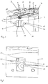
- FIG. 1 a section of a strand manufacturing machine 1 according to the invention with a format set 2 can be seen, which has a one-piece format base 3 and two format parts 6 and 7 placed on top.
- the strand production machine 1 has a bed 18 which is adapted to the shape of the format base 3 and into which the format base 3 is inserted in a form-fitting manner.
- the orientation of the format base 3 is defined by the shape and orientation of the bed 18, so that the format base 3 can only be used in one position.
- the format base 3 and the format parts 6 and 7 each have a shaping surface 11, which is to a total shaping area.
- the strand production machine 1 corresponds to the state of the art.
- the format base 3 and / or the format parts 6 or 7 have a higher hardness in the area of their shaping surfaces 11 than in their remaining surfaces, which can be achieved, for example, by local surface hardening such as electron beam hardening.
- the area 20 of the shaping surface 11 of the format base 3 is provided with the higher hardness, which can be seen to encompass the shaping surface 11 itself and the two adjacent edge sections of the upper side of the format base 3.
- the area 20 of higher hardness can extend exclusively over the shaping surface 11 or, alternatively, also extend to the edges of the upper side, so that the entire upper side of the format base 3 with the shaping surface 11 arranged therein is surface-hardened.
- the shaping surfaces 11 of the format parts 6 and 7 can also be hardened locally.
- the shaping surfaces 11 can also be hardened only in sections, provided that the higher hardness is not required in all areas of the shaping surfaces 11. It is only important for the invention that the shaping surfaces 11 have the higher hardness even in the required sections so that they are correspondingly wear-resistant and are accurate in shape. However, hardening beyond the shaping surfaces 11 can be acceptable if the higher hardness on the surfaces not belonging to the shaping surfaces does not interfere, in that the components no longer have to be processed there, or if the hardness expenditure can be reduced as a result by the hardening does not have to be precisely aligned with the shaping surfaces 11, for example.
- recesses 9 are provided, which are shaped and arranged in such a way that they complement each other to form a flow channel 10 after the format base 3 has been installed in the bed 18. Due to the deliberately only locally provided surface hardening, the format base 3 does not have a higher hardness on the underside in which the recess 9 is provided, which simplifies the recess 9 through subsequent processing such as milling and in a significantly shorter processing time in the format base 3 can be incorporated.
- the flow channel 10 can be produced considerably more easily, since the flow channel 10 is no longer implemented, as in the prior art, by a combination of bores provided in the format base 3, but instead here by a recess 9 in one of the surfaces, which by a substantially cheaper surface processing of the format base 3 can be realized. Furthermore, the heat dissipation can be intensified and evened out in that the flow channel 10 or the recess 9 is adapted to the shape and the course of the shaping surface 11. In addition, the amount of heat carried away by the cooling liquid can be increased by positioning the flow channel 10 or the surface of the flow channel 10 facing the shaping surface 11, along which the cooling liquid flows, closer to the shaping surface 11. The flow channel 10 is also through one between the abutting one another Enclosed circumferential seal 21 arranged on contact surfaces of the format base 3 and the bed 18, so that the cooling liquid cannot escape from the flow channel 10 into the environment.
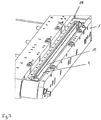
- a plurality of ribs 12 aligned parallel to one another in the longitudinal direction of the flow channel 10 are provided, which subdivide the flow channel 10 into three flow-related partial flow channels 13, 14 and 15. Furthermore, openings are provided in the end sections of the ribs 12, each of which forms an overflow point 16 and 17 for the cooling liquid flowing in the flow channel 10.
- the ribs 12 are formed here by two rails which are bent several times and connected to one another at one of their ends. The rails thus form a composite which is supported with the free ends of the rails at one end of the flow channel 10.
- an inflow point 22 opening into the flow channel 10 and an outflow point 23 are provided, through which the cooling liquid flows into the flow channel 10 and flows out again after flowing through the flow channel 10.
- the cooling liquid flows into the partial flow channel 13 through an inflow opening 24 provided at the inflow point 22 and flows further along the rib 12 to the overflow point 17, in which it flows into or over the middle partial flow channel 14.
- the cooling liquid flows in the opposite direction back in the direction of the inflow point 22 to a further overflow point 16, via which the cooling liquid flows into the upper partial flow channel 15 of the Figures 4 and 5 overflows.
- the cooling liquid then flows in the partial flow channel 15 from the overflow point 16 to the outflow point 23, in which it exits via an outflow opening that cannot be recognized.
- the cooling of the shaping surface 11 is thus further improved and intensified, in addition to the smaller distance between the flow channel 10, by the heat dissipation firstly by lengthening the flow path of the cooling liquid, here by almost tripling it, secondly by increasing the flow velocity due to the reduction in the free flow cross-section and thirdly by increasing the available heat dissipation surfaces through the ribs 12.
- the height of the ribs 12 is such that their edge sides rest against the base surfaces of the recesses 9 of the bed 18 and the format base 3 and thereby separate the partial flow channels 13, 14 and 15 from one another in terms of flow.
- the fluidic separation is then only canceled by the openings in the overflow points 16 and 17 so that the cooling liquid flows through the flow channel 10 several times lengthways in different directions and can specifically pass over at predetermined points between the adjacent partial flow channels 13, 14 and 15.
- Both the format base 3 and the format parts 6 and 7 can have a coating on their shaping surfaces 11, through which, for example, the higher hardness is achieved. Furthermore, the coating can also improve other or alternative properties, such as abrasion resistance, the coefficient of friction, dimensional stability at higher temperatures or the like.
- a coating in the form of a plasma ceramic with inclusions of polyether ether ketone (PEEK) has proven to be advantageous. It is sufficient if the format base 3 and / or the format parts 6 and 7 are provided with the coating only on their shaping surface 11. Furthermore, a material optimized with regard to the other material properties, such as aluminum for the format base 3 and / or the format parts 6 and 7, can be selected through the provided coating, since the desired surface properties are achieved through the coating.
Description
Die Erfindung betrifft eine Strangherstellmaschine zur Herstellung von Produkten der Tabak verarbeitenden Industrie mit den Merkmalen des Oberbegriffs von Anspruch 1 und eine zugehörige Formatgarnitur mit den Merkmalen des Oberbegriffs von Anspruch 6.The invention relates to a rod manufacturing machine for manufacturing products of the tobacco processing industry with the features of the preamble of
In Strangherstellmaschinen der Tabak verarbeitenden Industrie wird im Allgemeinen ein endloser Strang aus nicht formfixiertem Tabak oder Filtermaterial auf einen in Längsrichtung bewegten Umhüllungsstreifen aufgelegt und während der Transportbewegung des Umhüllungsstreifens durch Umlegen und Verkleben der Seitenränder des Umhüllungsstreifens zu einem festen Strang formfixiert. Alternativ werden in neueren Ausführungsformen von Filtern oder Abschnitten von Filtern auch Röhren verwendet, welche aus einem Streifen hergestellt werden und an der Außenseite zusätzlich mit Filtermaterial versehen sein können. Die Röhren können dazu zusätzlich an der Au-ßenseite ähnlich der herkömmlichen Filter durch einen Umhüllungsstreifen formfixiert sein. Zur Herstellung der Röhren wird der Streifen aus einer flachen Ausrichtung in die Röhrenform umgeschlagen und an den Seitenrändern verklebt. In diesem Fall ist der Strang durch eine endlose Röhre gebildet, welche in der Strangherstellmaschine geformt und an den Seitenrändern zur Formfixierung verklebt wird.In rod manufacturing machines in the tobacco processing industry, an endless rod of non-shape-fixed tobacco or filter material is generally placed on a wrapping strip that is moved in the longitudinal direction and is fixed in shape to form a solid strand during the transport movement of the wrapping strip by folding and gluing the side edges of the wrapping strip. Alternatively, in more recent embodiments of filters or sections of filters, tubes are also used, which are made from a strip and can additionally be provided with filter material on the outside. For this purpose, the tubes can also be fixed in shape on the outside, similar to conventional filters, by means of a covering strip. To produce the tubes, the strip is folded over from a flat orientation into the tube shape and glued at the side edges. In this case the strand is formed by an endless tube which is shaped in the strand manufacturing machine and glued to the side edges to fix the shape.
Zum Transport des Umhüllungsstreifens mit dem aufliegenden Strang oder des Streifens liegen diese auf einem endlosen, in Richtung der Transportbewegung angetriebenen Formatband auf. Das Formatband liegt wiederum auf einem Formatgrund auf, welcher aus einem oder mehreren Formatunterteilen gebildet ist, und mit einer Rinne versehen ist, die eine in Richtung der Transportbewegung zunehmende Tiefe mit einem abnehmenden Krümmungsradius aufweist. Aufgrund der in dem Formatgrund vorgesehenen Rinne mit dem abnehmenden Krümmungsradius wird das darauf anliegende Formatband mit dem aufliegenden Umhüllungsstreifen bzw. Streifen während der Transportbewegung mit den Seitenrändern seitlich des Stranges hochgeschlagen und in der unteren Hälfte zu einem halbkreisförmigen Querschnitt geformt. Nach dem Hochschlagen der Seitenränder werden diese durch weitere, die Rinne an der Oberseite zu einem Formgebungskanal verschließende Formatteile, oder auch Deckteile, um den Strang herumgelegt oder zu einer Röhre geformt, und dabei mittels einer in einem vorangegangenen Arbeitsschritt auf einem der Seitenränder angeordneten Leimspur miteinander verklebt. Unter dem Begriff "Seitenränder" des Umhüllungsstreifens bzw. des Streifens werden im Sinne dieser Anmeldung die seitlichen Randabschnitte des Umhüllungsstreifens oder des Streifens verstanden, welche zur Umhüllung des Stranges um diesen herumgeschlagen werden oder ausgehend von der U-Form weiter zu der Ringform umgeschlagen werden. Der Formatgrund und die Formatteile werden zusammen auch als Formatgarnitur bezeichnet und weisen jeweils eine Formgebungsfläche auf, welche sich zu einer Gesamtformgebungsfläche ergänzen und zur Herstellung eines Stranges einer vorbestimmten Geometrie ausgelegt bzw. bemessen sind. Sofern ein Strang mit einer anderen Geometrie bzw. einem anderen Durchmesser hergestellt werden soll, muss die Formatgarnitur gegen eine andere Formatgarnitur mit entsprechend daran angepassten Formgebungsflächen ausgetauscht werden.To transport the wrapping strip with the strand or strip lying on it, these lie on an endless format belt driven in the direction of the transport movement. The format tape in turn rests on a format base which is formed from one or more format lower parts and is provided with a groove which has a depth increasing in the direction of the transport movement with a decreasing radius of curvature. Due to the provided in the format reason Trough with the decreasing radius of curvature, the format tape lying thereon with the wrapping strip or strip lying thereon is turned up with the side edges on the side of the strand during the transport movement and shaped into a semicircular cross-section in the lower half. After the side edges have been turned up, they are laid around the strand or formed into a tube by means of further format parts, or cover parts, which close the channel on the top to form a shaping channel, and with one another by means of a glue track arranged on one of the side edges in a previous work step glued. The term "side edges" of the wrapping strip or the strip is understood in the context of this application to mean the lateral edge portions of the wrapping strip or the strip which are wrapped around the strand to wrap it or, starting from the U-shape, are wrapped further into the ring shape. The format base and the format parts are also referred to together as format fittings and each have a shaping surface, which complement one another to form an overall shaping surface and are designed or dimensioned for the production of a strand of a predetermined geometry. If a strand with a different geometry or a different diameter is to be produced, the format set must be exchanged for another format set with correspondingly adapted shaping surfaces.
Eine solche Strangherstellmaschine mit einer solchen Formatgarnitur ist zum Beispiel aus der
Ein Führungsteil an einer Maschine der tabakverarbeitenden Industrie mit einer Gleitfläche für ein Förderband oder ein streifenförmiges Hüllmaterial ist in
Aufgrund der hohen an die fertigen Produkte gestellten Qualitätsanforderungen sollte der den Strang zusammenhaltende Umhüllungsstreifen der fertigen Produkte möglichst faltenfrei und ohne Markierungen sein. Dazu ist es erforderlich, die Seitenränder des Umhüllungsstreifens nach dem seitlichen Hochschlagen möglichst sauber um den Strang herum- und schließlich aufeinanderzulegen, bevor sie miteinander verklebt werden. Damit unterliegen die Formgebungsflächen der Formatteile besonders hohen Anforderungen. Dabei sind insbesondere die hohen einzuhaltenden Anforderungen an die Formgenauigkeiten der Formgebungsflächen von wenigen Hundertsteln Millimetern ein besonderes Problem. Ferner unterliegen die Formgebungsflächen aufgrund des daran geführten Formatbandes einem erhöhten Verschleiß. Aus diesem Grunde werden die Formatteile in einem Härteofen einem besonderen Härteprozess unterzogen, was wiederum nachteilig für nachfolgend noch erforderliche Nachbearbeitungen der anderen Flächen der Formatteile ist, da sich dadurch die Bearbeitungszeiten der Nachbearbeitungen erheblich verlängern.Because of the high quality requirements placed on the finished products, the wrapping strip of the finished products that holds the strand together should be as free from creases as possible and without markings. For this it is necessary to lay the side edges of the wrapping strip around the strand as neatly as possible after turning it up at the side, and finally to lay them on top of one another before they are glued together. The shaping surfaces of the format parts are therefore subject to particularly high requirements. In particular, the high requirements to be met for the dimensional accuracy of the shaping surfaces of a few hundredths of a millimeter are a particular problem. Furthermore, the shaping surfaces are subject to increased wear due to the format tape guided on them. For this reason, the format parts are subjected to a special hardening process in a hardening furnace, which in turn is disadvantageous for any subsequent reworking of the other surfaces of the format parts, since this considerably increases the processing times of the reworking.
Ferner sollte die Reibung zwischen dem Formatband und den Formgebungsflächen der Formatteile möglichst gering sein, damit sich die Formatteile im Bereich der Formgebungsflächen möglichst wenig erwärmen. Dabei kann es nicht verhindert werden, dass sich die Formatteile trotzdem geringfügig erwärmen und deshalb gekühlt werden müssen. Die Kühlung der Formatteile erfolgt durch einen Flüssigkeitskreislauf mit mehreren in den Formatteilen angeordneten Strömungskanälen, welche von einer Kühlflüssigkeit durchströmt werden. Die Strömungskanäle werden in einem gesonderten Arbeitsgang gebohrt, wobei die Anordnung der Strömungskanäle eine gewisse Mindestwandstärke der Formatteile und/oder des Formatgrundes im Bereich der Strömungskanäle voraussetzt.Furthermore, the friction between the format tape and the shaping surfaces of the format parts should be as low as possible so that the format parts heat up as little as possible in the area of the shaping surfaces. It cannot be prevented that the format parts nevertheless heat up slightly and therefore have to be cooled. The format parts are cooled by a liquid circuit with several flow channels arranged in the format parts through which a cooling liquid flows. The flow channels are drilled in a separate operation, the arrangement of the flow channels presupposing a certain minimum wall thickness of the format parts and / or the format base in the area of the flow channels.
Vor diesem Hintergrund liegt der Erfindung die Aufgabe zugrunde, eine gattungsgemäße Strangherstellmaschine und eine Formatgarnitur bereitzustellen, welche kostengünstiger herzustellen sind. Außerdem soll mit der erfindungsgemäßen Strangherstellmaschine bzw. der vorgeschlagenen Formatgarnitur eine Herstellung eines Stranges mit einer verbesserten Formgenauigkeit möglich sein.Against this background, the invention is based on the object of providing a generic strand production machine and a format clothing which can be produced more cost-effectively. In addition, with the strand production machine according to the invention or the proposed format clothing, it should be possible to produce a strand with improved dimensional accuracy.
Zur Lösung der Aufgabe wird eine Strangherstellmaschine mit den Merkmalen des Anspruchs 1 und eine Formatgarnitur mit den Merkmalen von Anspruch 6vorgeschlagen. Weitere bevorzugte Weiterentwicklungen der Erfindung sind den Unteransprüchen, den Figuren und der zugehörigen Beschreibung zu entnehmen.To achieve the object, a strand manufacturing machine with the features of
Erfindungsgemäß wird vorgeschlagen, dass der Formatgrund und/oder wenigstens eines der Formatteile und/oder eine Gegenfläche der Strangherstellmaschine in einem Abschnitt eine Vertiefung aufweist, welche zusammen mit einer gegenüberliegenden Fläche des Formatgrundes und/oder des Formatteiles und/oder einer Gegenfläche der Strangherstellmaschine einen von einer Kühlflüssigkeit durchströmten Strömungskanal bildet. Der Strömungskanal wird damit statt durch eine Bohrung durch eine viel einfacher herzustellende Vertiefung an einem der Teile und eine gegenüberliegende Fläche des jeweils gegenüberliegenden Teils durch das Zusammensetzten der Teile gebildet. Dabei ist die Vertiefung in einer der Oberflächen des Formatgrundes und/oder des Formatteiles angeordnet, welche die geringere Härte aufweist. Dadurch wird der erfindungsgemäße Vorteil der aufgrund der geringeren Härte ermöglichten vereinfachten Bearbeitbarkeit der Oberfläche ausgenutzt, indem die Vertiefung nachträglich in die einfacher zu bearbeitende Oberfläche z.B. durch einen Fräsvorgang eingearbeitet wird. Ferner kann dadurch die Oberfläche der Formatgarnitur, an der die Kühlflüssigkeit vorbeiströmt, dichter an die zu kühlende Formgebungsfläche herangelegt werden, so dass der Wärmeabtransport von der Formgebungsfläche vergrößert werden kann. Damit kann die Formgebungsfläche auf eine niedrigere Temperatur gekühlt werden, oder es ist im Umkehrschluss möglich, den zur Kühlung der Formgebungsfläche auf ein vorbestimmtes Temperaturniveau erforderlichen Volumenstrom der Kühlflüssigkeit zu verringern. Ferner ist es auch möglich, die Formgebungsfläche aufgrund des vergrößerten Wärmeabtransportes durch einen einzigen Strömungskanal zu kühlen. Dazu kann die Vertiefung als eine breite Nut ausgebildet sein, welche in der Form und in dem Verlauf an die Form der Formgebungsfläche angepasst sein kann. Weiter wird vorgeschlagen, dass in dem Strömungskanal wenigstens eine in Längserstreckung des Strömungskanals ausgerichtete Rippe vorgesehen ist. Durch die Rippe kann die für den Wärmeabtransport zur Verfügung stehende Oberfläche und damit der Wärmeabtransport selbst weiter vergrößert werden. Da die Rippe in Längserstreckung, also in Strömungsrichtung der Kühlflüssigkeit ausgerichtet ist, wird verhindert, dass sich Wirbel oder Toträume an bzw. hinter der Rippe bilden, welche den Wärmeabtransport stören könnten. Vielmehr wird die Strömung dadurch nur so gering wie möglich gestört, und die Kühlflüssigkeit liegt in einer Laminarströmung an der Rippe an, was wiederum günstig für den Wärmeabtransport ist. Dabei wird weiter vorgeschlagen, dass die Rippe derart bemessen ist, dass sie den Strömungskanal in zwei, wenigstens abschnittsweise strömungstechnisch voneinander getrennte Teilströmungskanäle unterteilt, welche gemäß einer weiteren bevorzugten Ausführungsform der Erfindung an wenigstens einer Überströmstelle strömungstechnisch miteinander verbunden sind, wobei die Kühlflüssigkeit die Teilströmungskanäle bevorzugt nacheinander und in unterschiedliche Richtungen durchströmt. Die vorgeschlagene Weiterentwicklung weist hinsichtlich verschiedener Aspekte Vorteile auf. Erstens wird der von der Kühlflüssigkeit durchströmte Strömungsweg dadurch verlängert, so dass die Kühlflüssigkeit mehr Wärme aufnehmen und abtransportieren kann. Weiter wird der zur Verfügung stehende Strömungsquerschnitt verringert und die Strömungsgeschwindigkeit dadurch erhöht, wodurch der Wärmeabtransport ebenfalls weiter vergrößert werden kann. Die Rippe bildet dabei eine den Strömungskanal in zwei Teilströmungskanäle unterteilende Trennwand, welche von der Kühlflüssigkeit durch ein oder mehrere Umlenkungen in verschiedene Richtungen durchströmt werden.According to the invention it is proposed that the format base and / or at least one of the format parts and / or a counter surface of the strand production machine has a recess in a section which, together with an opposite surface of the format base and / or the format part and / or a counter surface of the strand production machine, has one of forms a flow channel through which a cooling liquid flows. The flow channel is thus formed, instead of a bore, through a recess, which is much easier to produce, on one of the parts and an opposite surface of the respective opposite part by assembling the parts. The recess is arranged in one of the surfaces of the format base and / or of the format part which has the lower hardness. In this way, the advantage according to the invention of the simplified machinability of the surface made possible due to the lower hardness is exploited, in that the depression is subsequently incorporated into the easier-to-machine surface, for example by a milling process. Furthermore, as a result, the surface of the format clothing, past which the cooling liquid flows, can be placed closer to the shaping surface to be cooled so that the heat dissipation from the shaping surface can be increased. In this way, the shaping surface can be cooled to a lower temperature, or, conversely, it is possible to reduce the volume flow of the cooling liquid required to cool the shaping surface to a predetermined temperature level. Furthermore, it is also possible to cool the shaping surface due to the increased heat dissipation through a single flow channel. For this purpose, the recess can be designed as a wide groove, which can be adapted in shape and in course to the shape of the shaping surface. It is further proposed that at least one rib aligned in the longitudinal extension of the flow channel is provided in the flow channel. The surface available for heat dissipation and thus the heat dissipation itself can be further enlarged by the rib. Since the rib is aligned in the longitudinal direction, that is to say in the direction of flow of the cooling liquid, vortices or dead spaces are prevented from forming on or behind the rib, which could interfere with the dissipation of heat. Rather, the flow is only disturbed as little as possible, and the cooling liquid lies against the rib in a laminar flow, which in turn is beneficial for heat dissipation. It is further proposed that the rib is dimensioned in such a way that it divides the flow channel into two at least partially fluidically separated partial flow channels which, according to a further preferred embodiment of the invention, are fluidically connected to one another at at least one overflow point, the cooling liquid preferring the partial flow channels flows through one after the other and in different directions. The proposed further development has advantages with regard to various aspects. Firstly, the flow path through which the cooling liquid flows is lengthened, so that the cooling liquid can absorb and transport away more heat. In addition, the available flow cross-section is reduced and the flow speed is increased as a result, which means that heat is dissipated can also be further enlarged. The rib forms a dividing wall which divides the flow channel into two partial flow channels through which the cooling liquid flows through one or more deflections in different directions.
Dabei kann der Formatgrund bevorzugt einstückig ausgebildet sein. Der Formatgrund mit der darauf vorgesehenen Formgebungsfläche kann damit als ein Teil einstückig hergestellt und montiert werden, wodurch die Montagezeiten und die Herstellkosten reduziert werden können. Die Herstellkosten werden dabei insbesondere deshalb verringert, da die bisher erforderliche hohe Fertigungs- und Montagegenauigkeit der bisher verwendeten Einzelteile des Formatgrundes entfällt. Bei den bisher verwendeten Einzelteilen mussten diese erstens sehr formgenau hergestellt und anschließend auf einer sehr formgenauen Gegenfläche der Strangherstellmaschine montiert werden, damit die abschließend zusammengesetzte Formgebungsfläche des Formatgrundes den geforderten Anforderungen entspricht. Sofern die Anforderungen nicht eingehalten wurden, mussten entweder die Gegenfläche oder die Einzelteile des Formatgrundes aufwendig nachbearbeitet werden. Gemäß der vorgeschlagenen Weiterentwicklung ist die Formgebungsfläche des Formatgrundes nun an einem einzigen Teil verwirklicht und kann an dieser entsprechend formgenau und individuell hergestellt werden. Dadurch entfällt die mögliche Fehlerquelle einer Formabweichung durch die bisher vorhandenen Stoßstellen der Einzelteile. Aufgrund der dadurch verbesserten Qualität der Formgebungsfläche kann ein Strang mit einer verbesserten Oberflächenqualität bei einem gleichzeitig reduzierten Verschleiß der Formgebungsfläche verwirklicht werden. Ferner kann durch die vorgeschlagene Lösung die erforderliche Umrüstzeit der Strangherstellmaschine bei einem Formatwechsel verkürzt werden.The format base can preferably be designed in one piece. The format base with the shaping surface provided on it can thus be manufactured and assembled in one piece as one part, as a result of which assembly times and manufacturing costs can be reduced. The manufacturing costs are reduced in particular because the previously required high manufacturing and assembly accuracy of the previously used individual parts of the format base is no longer necessary. In the case of the individual parts used up to now, they first had to be manufactured with great accuracy and then mounted on a very precise counter surface of the strand manufacturing machine so that the finally assembled shaping surface of the format base corresponds to the required requirements. If the requirements were not met, either the counter surface or the individual parts of the format base had to be laboriously reworked. According to the proposed further development, the shaping surface of the format base is now realized on a single part and can be produced on this with a correspondingly precise shape and individually. This eliminates the possible source of error of a form deviation due to the previously existing joints between the individual parts. As a result of the resulting improved quality of the shaping surface, a strand with an improved surface quality can be realized with a simultaneous reduction in wear on the shaping surface. Furthermore, the proposed solution can shorten the required retooling time of the strand manufacturing machine when changing formats.
Weiter wird vorgeschlagen, dass die höhere Härte der Formgebungsfläche durch eine lokale Oberflächenhärtung verwirklicht ist. Durch eine lokale Oberflächenhärtung kann die Formgebungsfläche gezielt bearbeitet und die gewünschte Härte verwirklicht werden, während die Härte der Bauteile in den verbleibenden Oberflächen zwecks einer einfacheren nachträglichen Bearbeitung gezielt nicht erhöht wird. Durch die lokale Oberflächenbearbeitung kann die Härte nur in gezielt ausgewählten Bereichen der Oberflächen bzw. Abschnitten der Formgebungsfläche erhöht werden, ohne dass dabei die Härte im Kern des Bauteils bzw. in den verbleibenden Oberflächen verändert bzw. erhöht wird. Solch eine lokale Oberflächenbehandlung mit einer entsprechend hohen zu erzielenden Oberflächenhärte kann z.B. ein Elektronenstrahlhärten sein. Ein weiterer Vorteil dieser Lösung ist darin zu sehen, dass im Vergleich zu den bisher verwendeten Verfahren mit einer Härtung der Bauteile in einem Härteofen nun die maximale Größe der Formatteile und der Formatgründe nicht mehr von der Größe des Härteofens abhängig ist. Damit wird die Grundlage dafür geschaffen, den Formatgrund und auch die Formatteile einstückig bzw. größer zu fertigen. Außerdem kann aufgrund der vorgeschlagenen Lösung der Härteaufwand insbesondere die Härtezeit reduziert werden, da die Teile nur gezielt im Bereich der Oberflächen der Formgebungsflächen oder im Bereich von Abschnitten der Formgebungsflächen gehärtet werden.It is also proposed that the higher hardness of the shaping surface is achieved by local surface hardening. Through a local Surface hardening, the shaping surface can be processed in a targeted manner and the desired hardness can be achieved, while the hardness of the components in the remaining surfaces is specifically not increased for the purpose of simpler subsequent processing. As a result of the local surface processing, the hardness can only be increased in specifically selected areas of the surfaces or sections of the shaping surface without the hardness in the core of the component or in the remaining surfaces being changed or increased. Such a local surface treatment with a correspondingly high surface hardness to be achieved can be, for example, electron beam hardening. Another advantage of this solution can be seen in the fact that, compared to the previously used methods with hardening of the components in a hardening furnace, the maximum size of the format parts and the reasons for the format are no longer dependent on the size of the hardening furnace. This creates the basis for manufacturing the format base and also the format parts in one piece or larger. In addition, due to the proposed solution, the hardening effort, in particular the hardening time, can be reduced, since the parts are only hardened in a targeted manner in the area of the surfaces of the shaping surfaces or in the area of sections of the shaping surfaces.
Dabei ermöglicht die Überströmstelle eine Umlenkung der Kühlflüssigkeit aus dem einen Teilströmungskanal in einen anderen Teilströmungskanal, während die strömungstechnische Trennung eine Vermischung der Kühlflüssigkeit verhindert bzw. das Strömen der Kühlflüssigkeit in unterschiedliche Richtungen erst ermöglicht.The overflow point enables the cooling liquid to be deflected from one partial flow channel into another partial flow channel, while the flow separation prevents mixing of the cooling liquid or enables the cooling liquid to flow in different directions in the first place.
Dabei kann die Kühlflüssigkeit derart geführt sein, dass sie zwischen den Teilströmungskanälen um einen Winkel von 180 Grad umgelenkt wird. Durch die vorgeschlagene Lösung kann das Strömen der Kühlflüssigkeit in den beiden Teilströmungskanälen sehr einfach durch eine langgestreckte Vertiefung mit einer mittig, parallel zu der Längserstreckung verlaufenden Rippe verwirklicht werden. Außerdem kann der zu durchströmende Strömungsweg dadurch maximal vergrößert werden, indem die Kühlflüssigkeit den Strömungskanal im Idealfall der Länge nach zweimal durchströmt. Dazu ist die Überströmstelle vorzugsweise an einem der Enden bzw. in einem der Enden der Rippe angeordnet. Dieser Vorteil kann durch eine vergrößerte Anzahl von Rippen und eine dadurch bewirkte mehrfache Umlenkung bzw. vergrößerte Kühlfläche weiter vergrößert werden.The cooling liquid can be guided in such a way that it is deflected between the partial flow channels by an angle of 180 degrees. The proposed solution allows the cooling liquid to flow in the two partial flow channels very easily through an elongated depression with a central rib running parallel to the longitudinal extension be realized. In addition, the flow path to be traversed can be increased to the maximum in that the cooling liquid ideally flows through the flow channel twice along its length. For this purpose, the overflow point is preferably arranged at one of the ends or in one of the ends of the rib. This advantage can be further increased by an increased number of ribs and a multiple deflection or enlarged cooling surface caused thereby.
Weiter wird vorgeschlagen, dass der Formatgrund und/oder wenigstens eines der Formatteile eine Beschichtung aufweist. Durch die Beschichtung können die Oberflächeneigenschaften des Formatgrundes und/oder der Formatteile in gezielt ausgewählten Bereichen entsprechend den Eigenschaften der Beschichtung gezielt verändert und verbessert werden. So ist es z.B. möglich die Gleiteigenschaften zu verbessern und/oder die Abriebfestigkeit zu erhöhen. Dabei kann insbesondere die vorgeschlagene Erhöhung der Härter durch die Beschichtung erreicht werden, indem ein Beschichtungswerkstoff mit einer höheren Härte gewählt wird.It is further proposed that the format base and / or at least one of the format parts have a coating. As a result of the coating, the surface properties of the format base and / or the format parts can be specifically changed and improved in specifically selected areas in accordance with the properties of the coating. For example, it is possible to improve the sliding properties and / or increase the abrasion resistance. In particular, the proposed increase in the hardener can be achieved by the coating by choosing a coating material with a higher hardness.
Dabei hat es sich als besonders vorteilhaft erwiesen, wenn die Beschichtung durch eine Plasmakeramik gebildet ist, und gemäß einer weiteren bevorzugten Weiterentwicklung in der Beschichtung Einlagerungen von Polyetherehterketon (PEEK) vorgesehen sind.It has proven to be particularly advantageous if the coating is formed by a plasma ceramic and, according to a further preferred further development, inclusions of polyether ether ketone (PEEK) are provided in the coating.
Weiter wird vorgeschlagen, dass der Formatgrund und/oder das Formatteil mit der Beschichtung aus Aluminium sind. Aluminium ist insofern von Vorteil, da es sehr leicht ist. Dabei wird die Verwendung von Aluminium als Werkstoff gezielt durch die vorgeschlagene Beschichtung ermöglicht, welche die erwünschte Abriebfestigkeit der Oberfläche ermöglicht. Damit ergänzen sich die Werkstoffvorteile des Aluminiums mit den Vorteilen der Beschichtung zu einem für den vorgesehenen Verwendungszweck optimierten Teil.It is also proposed that the format base and / or the format part with the coating be made of aluminum. Aluminum is advantageous in that it is very light. The use of aluminum as a material is specifically made possible by the proposed coating, which enables the desired abrasion resistance of the surface. In this way, the material advantages of aluminum and the advantages of the coating complement each other to form a part that is optimized for the intended use.
Es versteht sich von selbst, dass neben den Vorteilen, welche sich durch die verbesserte Härtung ergeben, auch die verbesserte Kühlung und die vorgeschlagene Beschichtung nebst der Kombination mit dem Aluminium als Werkstoff eine selbstständige Erfindung darstellen. Insbesondere ist der durch die Vertiefung geschaffene Strömungskanal erheblich einfacher herzustellen, und der Wärmeabtransport bzw. die Kühlung können durch die vorgeschlagenen Weiterentwicklungen erheblich intensiviert und verbessert werden.It goes without saying that in addition to the advantages that result from the improved hardening, the improved cooling and the proposed coating together with the combination with aluminum as a material represent an independent invention. In particular, the flow channel created by the depression is considerably easier to manufacture, and the heat removal or cooling can be considerably intensified and improved by the proposed further developments.
Die Erfindung wird im Folgenden anhand einer bevorzugten Ausführungsform unter Bezugnahme auf die beigefügten Figuren erläutert. Dabei zeigen:
- Fig. 1:
- einen Ausschnitt einer erfindungsgemäßen Strangherstellmaschine mit einer Formatgarnitur; und
- Fig. 2:
- einen vergrößerten Ausschnitt eines Abschnitts eines Strömungskanals der Strangherstellmaschine; und
- Fig. 3 bis 5:
- einen Ausschnitt der Strangherstellmaschine mit einer Vertiefung und einer darin angeordneten Rippe in verschiedenen Ansichten.
- Fig. 1:
- a section of a strand manufacturing machine according to the invention with a format clothing; and
- Fig. 2:
- an enlarged section of a portion of a flow channel of the strand manufacturing machine; and
- Fig. 3 to 5:
- a section of the strand production machine with a recess and a rib arranged therein in different views.
In der
Gemäß der vorgeschlagenen Erfindung weisen der Formatgrund 3 und/oder die Formatteile 6 oder 7 im Bereich ihrer Formgebungsflächen 11 eine höhere Härte auf als in ihren verbleibenden Oberflächen, was z.B. durch eine lokale Oberflächenhärtung wie z.B. eine Elektronenstrahlhärtung verwirklicht sein kann. In der
Ferner sind sowohl in dem Bett 18 der Strangherstellmaschine 1 als auch an der Unterseite des Formatgrundes 3 jeweils Vertiefungen 9 vorgesehen, welche so geformt und angeordnet sind, dass sie sich nach der Montage des Formatgrundes 3 in dem Bett 18 zu einem Strömungskanal 10 ergänzen. Aufgrund der bewusst nur lokal vorgesehenen Oberflächenhärtung weist der Formatgrund 3 an der Unterseite, in welcher die Vertiefung 9 vorgesehen ist, keine höhere Härte auf, wodurch die Vertiefung 9 durch eine nachträgliche Bearbeitung wie z.B. durch Fräsen vereinfacht und in einer erheblich kürzeren Bearbeitungszeit in den Formatgrund 3 eingearbeitet werden kann. Ferner kann der Strömungskanal 10 erheblich einfacher hergestellt werden, da der Strömungskanal 10 nicht mehr wie im Stand der Technik durch eine Kombination von in dem Formatgrund 3 vorgesehenen Bohrungen verwirklicht ist, sondern stattdessen hier durch eine Vertiefung 9 in einer der Oberflächen, welche durch eine wesentlich kostengünstigere Oberflächenbearbeitung des Formatgrundes 3 verwirklicht werden kann. Ferner kann die Wärmeabfuhr dadurch intensiviert und vergleichmäßigt werden, indem der Strömungskanal 10 bzw. die Vertiefung 9 an die Form und den Verlauf der Formgebungsfläche 11 angepasst ist. Außerdem kann die von der Kühlflüssigkeit abtransportierte Wärmemenge vergrößert werden, indem der Strömungskanal 10 bzw. die der Formgebungsfläche 11 zugewandte Fläche des Strömungskanals 10, an der die Kühlflüssigkeit entlang strömt, näher zu der Formgebungsfläche 11 positioniert wird. Der Strömungskanal 10 ist ferner durch eine zwischen den aneinander anliegenden Kontaktflächen des Formatgrundes 3 und des Bettes 18 angeordnete, umlaufende Dichtung 21 umfasst, so dass die Kühlflüssigkeit nicht aus dem Strömungskanal 10 in die Umgebung austreten kann.Furthermore, both in the
In den Vertiefungen 9 des Formatgrundes 3 und des Bettes 18 bzw. in dem Strömungskanal 10 sind mehrere in Längsrichtung des Strömungskanals 10, parallel zueinander ausgerichtete Rippen 12 vorgesehen, welche den Strömungskanal 10 in drei strömungstechnisch voneinander getrennte Teilströmungskanäle 13, 14 und 15 unterteilen. Ferner sind in den Endabschnitten der Rippen 12 jeweils Öffnungen vorgesehen, welche jeweils eine Überströmstelle 16 und 17 für die in dem Strömungskanal 10 strömende Kühlflüssigkeit bilden. Die Rippen 12 sind hier durch zwei Schienen gebildet, welche mehrfach gebogen und mit einem ihrer Enden miteinander verbunden sind. Die Schienen bilden damit einen Verbund, welcher sich mit den freien Enden der Schienen an einem Ende des Strömungskanals 10 abstützt. Ferner sind eine in den Strömungskanal 10 mündende Einströmstelle 22 und eine Ausströmstelle 23 vorgesehen, durch welche die Kühlflüssigkeit in den Strömungskanal 10 einströmt und nach dem Durchströmen des Strömungskanals 10 wieder ausströmt. Die Kühlflüssigkeit strömt durch eine an der Einströmstelle 22 vorgesehene Einströmöffnung 24 in den Teilströmungskanal 13 ein und strömt weiter entlang der Rippe 12 bis zu der Überströmstelle 17, in welcher sie in den mittleren Teilströmungskanal 14 ein- bzw. überströmt. Abschließend strömt die Kühlflüssigkeit in die entgegengesetzte Richtung zurück in Richtung der Einströmstelle 22 bis zu einer weiteren Überströmstelle 16, über welche die Kühlflüssigkeit in den oberen Teilströmungskanal 15 der
Die strömungstechnische Trennung wird dann nur durch die Öffnungen in den Überströmstellen 16 und 17 aufgehoben, damit die Kühlflüssigkeit den Strömungskanal 10 mehrfach der Länge nach, in unterschiedliche Richtungen durchströmt und dazu gezielt an vorbestimmten Stellen zwischen den benachbarten Teilströmungskanälen 13, 14 und 15 übertreten kann.The fluidic separation is then only canceled by the openings in the overflow points 16 and 17 so that the cooling liquid flows through the
Sowohl der Formatgrund 3 als auch die Formatteile 6 und 7 können auf ihren Formgebungsflächen 11 eine Beschichtung aufweisen, durch welche z.B. die höhere Härte verwirklicht ist. Ferner können durch die Beschichtung aber auch weitere oder alternative Eigenschaften verbessert werden, wie z.B. die Abriebfestigkeit, der Reibkoeffizient, die Formstabilität bei höheren Temperaturen oder dergleichen. Bevorzugt hat sich eine Beschichtung in Form einer Plasmakeramik mit Einlagerungen von Polyetherehterketon (PEEK) als vorteilhaft erwiesen. Dabei reicht es aus, wenn der Formatgrund 3 und/oder die Formatteile 6 und 7 nur auf ihrer Formgebungsfläche 11 mit der Beschichtung versehen sind. Ferner kann durch die vorgesehene Beschichtung ein hinsichtlich der weiteren Werkstoffeigenschaften optimierter Werkstoff wie z.B. Aluminium für den Formatgrund 3 und/oder die Formatteile 6 und 7 gewählt werden, da die gewünschten Oberflächeneigenschaften durch die Beschichtung erreicht werden.Both the
Claims (15)
- Rod manufacturing machine (1) for manufacturing products of the tobacco processing industry with- a format garniture (2) with- a format base (3) and one or more garniture components (6, 7), and- a garniture tape (4) performing a transport movement, and- a wrapping strip (5) resting on the garniture tape (4) and moved by the transport movement of the garniture tape (4), wherein- the format base (3) and the garniture components (6, 7) each have a shaping surface (11) against which the garniture tape (4) or the wrapping strip (5) resting thereon are in contact, wherein- the shaping surfaces (11) have a shaping which forces the garniture tape (4) during the transport movement together with the overlying wrapping strip (5) out of a flat alignment into an alignment which is U-shaped in cross-section,wherein- the format base (3) and/or at least one of the garniture components (6, 7) have a higher hardness at least in a section of their shaping surface (11) than in the region of the remaining surfaces, characterized in that- the format base (3) and/or at least one of the garniture components (6, 7) and/or a surface (8) of the rod manufacturing machine (1) has in a section a recess (9) which, together with an opposite surface of the format base (3) and/or of the garniture component (6, 7) and/or a surface (8) of the rod manufacturing machine (1), forms a flow channel (10) through which a cooling liquid flows, wherein- the recess (9) is arranged in one of the surfaces of the format base (3) and/or of the garniture components (6, 7) which has the lower hardness, wherein- at least one rib (12) aligned in longitudinal extension of the flow channel (10) is provided in the flow channel (10), wherein- the rib (12) is dimensioned in such a way that it divides the flow channel (10) into two partial flow channels (13, 14, 15) which are separated from one another in terms of flow at least in sections.
- Rod manufacturing machine (1) according to claim 1, characterized in that- the format base (3) is formed in one piece.
- Rod manufacturing machine (1) according to claim 1 or 2, characterized in that- the higher hardness of the shaping surface (11) is formed by local surface hardening.
- Rod manufacturing machine (1) according to one of the claims 1 to 3, characterized in that- the partial flow channels (13, 14, 15) are fluidically connected to one another at at least one overflow point (16, 17), and- the cooling liquid flows through the partial flow channels (13, 14, 15) successively in different directions.
- Rod manufacturing machine (1) according to one of the claims 1 to 4 or 6, characterized in that- the cooling liquid between the partial flow channels (13,14,15) is deflected by an angle of 180 degrees.
- Format garniture (2) for the manufacture of products of the tobacco processing industry, having- a format base (3) and one or more garniture components (6, 7), wherein- the format base (3) and the garniture components (6, 7) each have a shaping surface (11) for the contact of a garniture tape (4) and a wrapping strip (5) resting thereon, wherein- the shaping surfaces (11) have a shaping which forces the adjacent garniture tape (4) during a transport movement together with the overlying wrapping strip (5) out of a flat orientation into an orientation which is U-shaped in cross-section,wherein- the format base (3) and/or at least one of the garniture components (6, 7) have a higher hardness at least in a section of their shaping surface (11) than in the region of the remaining surfaces, characterized in that- the format base (3) and/or at least one of the garniture components (6, 7) has, in a section, a recess (9) which, together with a surface (8) of a rod manufacturing machine (1), forms a flow channel (10) through which a cooling liquid flows, wherein- at least one rib (12) aligned in the longitudinal extension of the recess (9) is provided in the recess (9), wherein- the rib (12) is dimensioned in such a way that it divides the flow channel (10) into two partial flow channels (13, 14, 15) which are separated from one another at least in sections in terms of flow.
- Format garniture (2) according to claim 6, characterized in that- the format base (3) is formed in one piece.
- Format garniture (2) according to claim 6 or 7, characterized in that- the higher hardness of the shaping surface (11) is formed by local surface hardening.
- Format garniture (2) according to one of the preceding claims 6 to 8, characterized in that- the recess (9) is arranged in one of the surfaces of the format base (3) and/or of the garniture components (6, 7) which has the lower hardness.
- Format garniture (2) according to one of the claims 6 to 9, characterized in that- the partial flow channels (13, 14, 15) are fluidically connected to one another at at least one overflow point (16, 17), and- the cooling liquid flows through the partial flow channels (13, 14, 15) successively in different directions.
- Format garniture (2) according to one of the claims 6 or 10, characterized in that- the cooling liquid is deflected by an angle of 180 degrees between the partial flow channels (13, 14, 15).
- Format garniture (2) according to one of the claims 6 to 11, characterized in that- the format base (3) and/or at least one of the garniture components (6, 7) has a coating.
- Format garniture (2) according to claim 12, characterized in that- the coating is formed by a plasma ceramic.
- Format garniture (2) according to one of the claims 12 or 13, characterized in that- in the coating, intercalations of polyether ether ketone (PEEK) are provided.
- Format garniture (2) according to one of the claims 12 to 14, characterized in that- the format base (3) and/or the garniture component (6, 7) with the coating are made of aluminum.
Priority Applications (1)
| Application Number | Priority Date | Filing Date | Title |
|---|---|---|---|
| PL17200584T PL3320788T3 (en) | 2016-11-11 | 2017-11-08 | Machine for producing rod-shaped products for the tobacco processing industry and related forming set |
Applications Claiming Priority (1)
| Application Number | Priority Date | Filing Date | Title |
|---|---|---|---|
| DE102016121618.6A DE102016121618A1 (en) | 2016-11-11 | 2016-11-11 | Strand making machine for the manufacture of tobacco industry products and associated garniture |
Publications (2)
| Publication Number | Publication Date |
|---|---|
| EP3320788A1 EP3320788A1 (en) | 2018-05-16 |
| EP3320788B1 true EP3320788B1 (en) | 2021-04-21 |
Family
ID=60269771
Family Applications (1)
| Application Number | Title | Priority Date | Filing Date |
|---|---|---|---|
| EP17200584.5A Active EP3320788B1 (en) | 2016-11-11 | 2017-11-08 | Machine for producing rod-shaped products for the tobacco processing industry and related forming set |
Country Status (3)
| Country | Link |
|---|---|
| EP (1) | EP3320788B1 (en) |
| DE (1) | DE102016121618A1 (en) |
| PL (1) | PL3320788T3 (en) |
Families Citing this family (2)
| Publication number | Priority date | Publication date | Assignee | Title |
|---|---|---|---|---|
| BR112021001407A2 (en) * | 2018-08-03 | 2021-04-27 | Philip Morris Products S.A. | reconfigurable packaging mechanism |
| JP7407168B2 (en) | 2018-08-03 | 2023-12-28 | フィリップ・モーリス・プロダクツ・ソシエテ・アノニム | Reconfigurable wrapping mechanism |
Citations (10)
| Publication number | Priority date | Publication date | Assignee | Title |
|---|---|---|---|---|
| GB514162A (en) | 1938-03-29 | 1939-11-01 | Desmond Walter Molins | Improvements in or relating to machines for forming a continuous tobacco rod or filler |
| GB1454004A (en) | 1973-03-08 | 1976-10-27 | Hauni Werke Koerber & Co Kg | Method and apparatus for the manufacture of rod-like articles of the tobacco industry |
| DE2531488A1 (en) | 1975-07-15 | 1977-02-03 | Hauni Werke Koerber & Co Kg | Guides for cigarette former - have diamond particles bonded to curved trough faces |
| JPH07184625A (en) | 1993-12-27 | 1995-07-25 | Japan Tobacco Inc | Apparatus for feeding sharedded tobacco to cigarette production machine |
| JP2997246B1 (en) | 1998-08-11 | 2000-01-11 | 日本たばこ産業株式会社 | Compression molding equipment for cigarette manufacturing machines |
| US20030136419A1 (en) | 2002-01-24 | 2003-07-24 | Hauni Maschinenbau Ag | Garniture tongue of a garniture device |
| EP1342421A1 (en) | 2000-12-13 | 2003-09-10 | Japan Tobacco Inc. | Machine for manufacturing rod-like article |
| US20040118416A1 (en) | 2002-12-20 | 2004-06-24 | Seymour Sydney Keith | Equipment and methods for manufacturing cigarettes |
| DE102010051894A1 (en) | 2010-11-22 | 2012-05-24 | Hauni Maschinenbau Ag | Format system and format parts for a strand production machine of the tobacco processing industry |
| US20140048083A1 (en) | 2012-08-20 | 2014-02-20 | Altria Client Services Inc. | Rod forming appartus |
Family Cites Families (2)
| Publication number | Priority date | Publication date | Assignee | Title |
|---|---|---|---|---|
| IT1191811B (en) | 1985-08-02 | 1988-03-23 | Hauni Werke Koerber & Co Kg | TRAINER ACCESSORY FOR A TRAINER OF A LODGING OF THE TOBACCO INDUSTRY |
| DE4225644A1 (en) * | 1992-08-03 | 1994-02-10 | Koerber Ag | Device for stripping tobacco particles from a conveyor |
-
2016
- 2016-11-11 DE DE102016121618.6A patent/DE102016121618A1/en active Pending
-
2017
- 2017-11-08 PL PL17200584T patent/PL3320788T3/en unknown
- 2017-11-08 EP EP17200584.5A patent/EP3320788B1/en active Active
Patent Citations (10)
| Publication number | Priority date | Publication date | Assignee | Title |
|---|---|---|---|---|
| GB514162A (en) | 1938-03-29 | 1939-11-01 | Desmond Walter Molins | Improvements in or relating to machines for forming a continuous tobacco rod or filler |
| GB1454004A (en) | 1973-03-08 | 1976-10-27 | Hauni Werke Koerber & Co Kg | Method and apparatus for the manufacture of rod-like articles of the tobacco industry |
| DE2531488A1 (en) | 1975-07-15 | 1977-02-03 | Hauni Werke Koerber & Co Kg | Guides for cigarette former - have diamond particles bonded to curved trough faces |
| JPH07184625A (en) | 1993-12-27 | 1995-07-25 | Japan Tobacco Inc | Apparatus for feeding sharedded tobacco to cigarette production machine |
| JP2997246B1 (en) | 1998-08-11 | 2000-01-11 | 日本たばこ産業株式会社 | Compression molding equipment for cigarette manufacturing machines |
| EP1342421A1 (en) | 2000-12-13 | 2003-09-10 | Japan Tobacco Inc. | Machine for manufacturing rod-like article |
| US20030136419A1 (en) | 2002-01-24 | 2003-07-24 | Hauni Maschinenbau Ag | Garniture tongue of a garniture device |
| US20040118416A1 (en) | 2002-12-20 | 2004-06-24 | Seymour Sydney Keith | Equipment and methods for manufacturing cigarettes |
| DE102010051894A1 (en) | 2010-11-22 | 2012-05-24 | Hauni Maschinenbau Ag | Format system and format parts for a strand production machine of the tobacco processing industry |
| US20140048083A1 (en) | 2012-08-20 | 2014-02-20 | Altria Client Services Inc. | Rod forming appartus |
Also Published As
| Publication number | Publication date |
|---|---|
| EP3320788A1 (en) | 2018-05-16 |
| PL3320788T3 (en) | 2021-11-02 |
| DE102016121618A1 (en) | 2018-05-17 |
Similar Documents
| Publication | Publication Date | Title |
|---|---|---|
| EP2611990B1 (en) | Turbine blade for a gas turbine | |
| DE2839552C3 (en) | Nozzle head for the production of plastic granulate | |
| EP3621463B1 (en) | Cooling nozzle for extruders | |
| DE3304783C2 (en) | ||
| EP3320788B1 (en) | Machine for producing rod-shaped products for the tobacco processing industry and related forming set | |
| EP4105506A1 (en) | Cage segment for a roller bearing cage | |
| DE3347869C2 (en) | ||
| EP1561968A1 (en) | Tension or guide rail with installation channel | |
| DE2707907A1 (en) | Water cooled roll esp. guide roll in steel casting plant - with spiral internal passages for flow of water to give effective cooling without distortion | |
| DE102006055873B4 (en) | Channel wall element | |
| DE2607822C3 (en) | Headbox for paper machines | |
| DE4114488C1 (en) | ||
| DE2155344A1 (en) | INTEGRAL TURBINE WHEEL WITH OPEN AXIAL BREAKTHROUGHTS ON THE OUTER WREATH AND CONTROLLED WREATH Cracks | |
| DE10006380A1 (en) | Device for the production of profiled plastic pipes | |
| EP3349961B1 (en) | Device for producing plastic tubing | |
| EP3087254B1 (en) | Component that can be charged with hot gas for a gas turbine and sealing assembly with such a component | |
| DE102011006647B4 (en) | Mechanical device for realizing an opening with variable opening widths | |
| EP3333484B1 (en) | Tile of a gas turbine | |
| DE102017103329A1 (en) | Nozzle for applying highly viscous material | |
| EP3074649B1 (en) | Spacer for a sliding guide and lifting post | |
| EP1954954B1 (en) | Linear rolling bearing | |
| DE102007030506A1 (en) | Curved guide rail | |
| EP3548204B1 (en) | Casting nozzle | |
| DE10230489A1 (en) | Rail is mounted on support plate above support structure, slide being positioned between the two, allowing support plate to move along length of rail | |
| DE10033465B4 (en) | Turbine guide wheel and method for producing a turbine guide wheel |
Legal Events
| Date | Code | Title | Description |
|---|---|---|---|
| PUAI | Public reference made under article 153(3) epc to a published international application that has entered the european phase |
Free format text: ORIGINAL CODE: 0009012 |
|
| STAA | Information on the status of an ep patent application or granted ep patent |
Free format text: STATUS: THE APPLICATION HAS BEEN PUBLISHED |
|
| AK | Designated contracting states |
Kind code of ref document: A1 Designated state(s): AL AT BE BG CH CY CZ DE DK EE ES FI FR GB GR HR HU IE IS IT LI LT LU LV MC MK MT NL NO PL PT RO RS SE SI SK SM TR |
|
| AX | Request for extension of the european patent |
Extension state: BA ME |
|
| STAA | Information on the status of an ep patent application or granted ep patent |
Free format text: STATUS: REQUEST FOR EXAMINATION WAS MADE |
|
| 17P | Request for examination filed |
Effective date: 20181023 |
|
| RBV | Designated contracting states (corrected) |
Designated state(s): AL AT BE BG CH CY CZ DE DK EE ES FI FR GB GR HR HU IE IS IT LI LT LU LV MC MK MT NL NO PL PT RO RS SE SI SK SM TR |
|
| STAA | Information on the status of an ep patent application or granted ep patent |
Free format text: STATUS: EXAMINATION IS IN PROGRESS |
|
| 17Q | First examination report despatched |
Effective date: 20200401 |
|
| GRAP | Despatch of communication of intention to grant a patent |
Free format text: ORIGINAL CODE: EPIDOSNIGR1 |
|
| STAA | Information on the status of an ep patent application or granted ep patent |
Free format text: STATUS: GRANT OF PATENT IS INTENDED |
|
| INTG | Intention to grant announced |
Effective date: 20201120 |
|
| GRAS | Grant fee paid |
Free format text: ORIGINAL CODE: EPIDOSNIGR3 |
|
| GRAA | (expected) grant |
Free format text: ORIGINAL CODE: 0009210 |
|
| STAA | Information on the status of an ep patent application or granted ep patent |
Free format text: STATUS: THE PATENT HAS BEEN GRANTED |
|
| AK | Designated contracting states |
Kind code of ref document: B1 Designated state(s): AL AT BE BG CH CY CZ DE DK EE ES FI FR GB GR HR HU IE IS IT LI LT LU LV MC MK MT NL NO PL PT RO RS SE SI SK SM TR |
|
| REG | Reference to a national code |
Ref country code: GB Ref legal event code: FG4D Free format text: NOT ENGLISH |
|
| REG | Reference to a national code |
Ref country code: CH Ref legal event code: EP |
|
| REG | Reference to a national code |
Ref country code: DE Ref legal event code: R096 Ref document number: 502017010126 Country of ref document: DE Ref country code: IE Ref legal event code: FG4D Free format text: LANGUAGE OF EP DOCUMENT: GERMAN |
|
| REG | Reference to a national code |
Ref country code: AT Ref legal event code: REF Ref document number: 1383698 Country of ref document: AT Kind code of ref document: T Effective date: 20210515 |
|
| REG | Reference to a national code |
Ref country code: NL Ref legal event code: FP |
|
| REG | Reference to a national code |
Ref country code: LT Ref legal event code: MG9D |
|
| PG25 | Lapsed in a contracting state [announced via postgrant information from national office to epo] |
Ref country code: HR Free format text: LAPSE BECAUSE OF FAILURE TO SUBMIT A TRANSLATION OF THE DESCRIPTION OR TO PAY THE FEE WITHIN THE PRESCRIBED TIME-LIMIT Effective date: 20210421 Ref country code: BG Free format text: LAPSE BECAUSE OF FAILURE TO SUBMIT A TRANSLATION OF THE DESCRIPTION OR TO PAY THE FEE WITHIN THE PRESCRIBED TIME-LIMIT Effective date: 20210721 Ref country code: LT Free format text: LAPSE BECAUSE OF FAILURE TO SUBMIT A TRANSLATION OF THE DESCRIPTION OR TO PAY THE FEE WITHIN THE PRESCRIBED TIME-LIMIT Effective date: 20210421 Ref country code: FI Free format text: LAPSE BECAUSE OF FAILURE TO SUBMIT A TRANSLATION OF THE DESCRIPTION OR TO PAY THE FEE WITHIN THE PRESCRIBED TIME-LIMIT Effective date: 20210421 |
|
| PG25 | Lapsed in a contracting state [announced via postgrant information from national office to epo] |
Ref country code: SE Free format text: LAPSE BECAUSE OF FAILURE TO SUBMIT A TRANSLATION OF THE DESCRIPTION OR TO PAY THE FEE WITHIN THE PRESCRIBED TIME-LIMIT Effective date: 20210421 Ref country code: RS Free format text: LAPSE BECAUSE OF FAILURE TO SUBMIT A TRANSLATION OF THE DESCRIPTION OR TO PAY THE FEE WITHIN THE PRESCRIBED TIME-LIMIT Effective date: 20210421 Ref country code: NO Free format text: LAPSE BECAUSE OF FAILURE TO SUBMIT A TRANSLATION OF THE DESCRIPTION OR TO PAY THE FEE WITHIN THE PRESCRIBED TIME-LIMIT Effective date: 20210721 Ref country code: PT Free format text: LAPSE BECAUSE OF FAILURE TO SUBMIT A TRANSLATION OF THE DESCRIPTION OR TO PAY THE FEE WITHIN THE PRESCRIBED TIME-LIMIT Effective date: 20210823 Ref country code: IS Free format text: LAPSE BECAUSE OF FAILURE TO SUBMIT A TRANSLATION OF THE DESCRIPTION OR TO PAY THE FEE WITHIN THE PRESCRIBED TIME-LIMIT Effective date: 20210821 Ref country code: GR Free format text: LAPSE BECAUSE OF FAILURE TO SUBMIT A TRANSLATION OF THE DESCRIPTION OR TO PAY THE FEE WITHIN THE PRESCRIBED TIME-LIMIT Effective date: 20210722 Ref country code: LV Free format text: LAPSE BECAUSE OF FAILURE TO SUBMIT A TRANSLATION OF THE DESCRIPTION OR TO PAY THE FEE WITHIN THE PRESCRIBED TIME-LIMIT Effective date: 20210421 |
|
| REG | Reference to a national code |
Ref country code: DE Ref legal event code: R026 Ref document number: 502017010126 Country of ref document: DE |
|
| PLBI | Opposition filed |
Free format text: ORIGINAL CODE: 0009260 |
|
| PG25 | Lapsed in a contracting state [announced via postgrant information from national office to epo] |
Ref country code: DK Free format text: LAPSE BECAUSE OF FAILURE TO SUBMIT A TRANSLATION OF THE DESCRIPTION OR TO PAY THE FEE WITHIN THE PRESCRIBED TIME-LIMIT Effective date: 20210421 Ref country code: EE Free format text: LAPSE BECAUSE OF FAILURE TO SUBMIT A TRANSLATION OF THE DESCRIPTION OR TO PAY THE FEE WITHIN THE PRESCRIBED TIME-LIMIT Effective date: 20210421 Ref country code: CZ Free format text: LAPSE BECAUSE OF FAILURE TO SUBMIT A TRANSLATION OF THE DESCRIPTION OR TO PAY THE FEE WITHIN THE PRESCRIBED TIME-LIMIT Effective date: 20210421 Ref country code: RO Free format text: LAPSE BECAUSE OF FAILURE TO SUBMIT A TRANSLATION OF THE DESCRIPTION OR TO PAY THE FEE WITHIN THE PRESCRIBED TIME-LIMIT Effective date: 20210421 Ref country code: ES Free format text: LAPSE BECAUSE OF FAILURE TO SUBMIT A TRANSLATION OF THE DESCRIPTION OR TO PAY THE FEE WITHIN THE PRESCRIBED TIME-LIMIT Effective date: 20210421 Ref country code: SM Free format text: LAPSE BECAUSE OF FAILURE TO SUBMIT A TRANSLATION OF THE DESCRIPTION OR TO PAY THE FEE WITHIN THE PRESCRIBED TIME-LIMIT Effective date: 20210421 Ref country code: SK Free format text: LAPSE BECAUSE OF FAILURE TO SUBMIT A TRANSLATION OF THE DESCRIPTION OR TO PAY THE FEE WITHIN THE PRESCRIBED TIME-LIMIT Effective date: 20210421 |
|
| PLAX | Notice of opposition and request to file observation + time limit sent |
Free format text: ORIGINAL CODE: EPIDOSNOBS2 |
|
| 26 | Opposition filed |
Opponent name: G.D SOCIETA PER AZIONI Effective date: 20220121 |
|
| PLBB | Reply of patent proprietor to notice(s) of opposition received |
Free format text: ORIGINAL CODE: EPIDOSNOBS3 |
|
| PG25 | Lapsed in a contracting state [announced via postgrant information from national office to epo] |
Ref country code: IS Free format text: LAPSE BECAUSE OF FAILURE TO SUBMIT A TRANSLATION OF THE DESCRIPTION OR TO PAY THE FEE WITHIN THE PRESCRIBED TIME-LIMIT Effective date: 20210821 Ref country code: AL Free format text: LAPSE BECAUSE OF FAILURE TO SUBMIT A TRANSLATION OF THE DESCRIPTION OR TO PAY THE FEE WITHIN THE PRESCRIBED TIME-LIMIT Effective date: 20210421 |
|
| PG25 | Lapsed in a contracting state [announced via postgrant information from national office to epo] |
Ref country code: MC Free format text: LAPSE BECAUSE OF FAILURE TO SUBMIT A TRANSLATION OF THE DESCRIPTION OR TO PAY THE FEE WITHIN THE PRESCRIBED TIME-LIMIT Effective date: 20210421 |
|
| REG | Reference to a national code |
Ref country code: CH Ref legal event code: PL |
|
| GBPC | Gb: european patent ceased through non-payment of renewal fee |
Effective date: 20211108 |
|
| PG25 | Lapsed in a contracting state [announced via postgrant information from national office to epo] |
Ref country code: LU Free format text: LAPSE BECAUSE OF NON-PAYMENT OF DUE FEES Effective date: 20211108 Ref country code: BE Free format text: LAPSE BECAUSE OF NON-PAYMENT OF DUE FEES Effective date: 20211130 |
|
| REG | Reference to a national code |
Ref country code: BE Ref legal event code: MM Effective date: 20211130 |
|
| REG | Reference to a national code |
Ref country code: DE Ref legal event code: R081 Ref document number: 502017010126 Country of ref document: DE Owner name: KOERBER TECHNOLOGIES GMBH, DE Free format text: FORMER OWNER: HAUNI MASCHINENBAU GMBH, 21033 HAMBURG, DE |
|
| PG25 | Lapsed in a contracting state [announced via postgrant information from national office to epo] |
Ref country code: IE Free format text: LAPSE BECAUSE OF NON-PAYMENT OF DUE FEES Effective date: 20211108 Ref country code: GB Free format text: LAPSE BECAUSE OF NON-PAYMENT OF DUE FEES Effective date: 20211108 |
|
| REG | Reference to a national code |
Ref country code: NL Ref legal event code: HC Owner name: KOERBER TECHNOLOGIES GMBH; DE Free format text: DETAILS ASSIGNMENT: CHANGE OF OWNER(S), CHANGE OF OWNER(S) NAME; FORMER OWNER NAME: HAUNI MASCHINENBAU GMBH Effective date: 20221031 |
|
| PG25 | Lapsed in a contracting state [announced via postgrant information from national office to epo] |
Ref country code: FR Free format text: LAPSE BECAUSE OF NON-PAYMENT OF DUE FEES Effective date: 20211130 |
|
| RAP4 | Party data changed (patent owner data changed or rights of a patent transferred) |
Owner name: KOERBER TECHNOLOGIES GMBH |
|
| PGFP | Annual fee paid to national office [announced via postgrant information from national office to epo] |
Ref country code: PL Payment date: 20221025 Year of fee payment: 6 |
|
| PG25 | Lapsed in a contracting state [announced via postgrant information from national office to epo] |
Ref country code: HU Free format text: LAPSE BECAUSE OF FAILURE TO SUBMIT A TRANSLATION OF THE DESCRIPTION OR TO PAY THE FEE WITHIN THE PRESCRIBED TIME-LIMIT; INVALID AB INITIO Effective date: 20171108 |
|
| PG25 | Lapsed in a contracting state [announced via postgrant information from national office to epo] |
Ref country code: CY Free format text: LAPSE BECAUSE OF FAILURE TO SUBMIT A TRANSLATION OF THE DESCRIPTION OR TO PAY THE FEE WITHIN THE PRESCRIBED TIME-LIMIT Effective date: 20210421 |
|
| P01 | Opt-out of the competence of the unified patent court (upc) registered |
Effective date: 20230616 |
|
| PG25 | Lapsed in a contracting state [announced via postgrant information from national office to epo] |
Ref country code: LI Free format text: LAPSE BECAUSE OF NON-PAYMENT OF DUE FEES Effective date: 20220701 Ref country code: CH Free format text: LAPSE BECAUSE OF NON-PAYMENT OF DUE FEES Effective date: 20220701 |
|
| PGFP | Annual fee paid to national office [announced via postgrant information from national office to epo] |
Ref country code: NL Payment date: 20231127 Year of fee payment: 7 |
|
| REG | Reference to a national code |
Ref country code: AT Ref legal event code: MM01 Ref document number: 1383698 Country of ref document: AT Kind code of ref document: T Effective date: 20221108 |
|
| PG25 | Lapsed in a contracting state [announced via postgrant information from national office to epo] |
Ref country code: AT Free format text: LAPSE BECAUSE OF NON-PAYMENT OF DUE FEES Effective date: 20221108 |
|
| PGFP | Annual fee paid to national office [announced via postgrant information from national office to epo] |
Ref country code: IT Payment date: 20231129 Year of fee payment: 7 Ref country code: DE Payment date: 20231121 Year of fee payment: 7 |
|
| PGFP | Annual fee paid to national office [announced via postgrant information from national office to epo] |
Ref country code: PL Payment date: 20231023 Year of fee payment: 7 |