EP3320771B1 - Futteranlage mit trogreinigung - Google Patents
Futteranlage mit trogreinigung Download PDFInfo
- Publication number
- EP3320771B1 EP3320771B1 EP17200629.8A EP17200629A EP3320771B1 EP 3320771 B1 EP3320771 B1 EP 3320771B1 EP 17200629 A EP17200629 A EP 17200629A EP 3320771 B1 EP3320771 B1 EP 3320771B1
- Authority
- EP
- European Patent Office
- Prior art keywords
- feed
- valve
- supply
- ring line
- trough
- Prior art date
- Legal status (The legal status is an assumption and is not a legal conclusion. Google has not performed a legal analysis and makes no representation as to the accuracy of the status listed.)
- Active
Links
Images

Classifications
-
- A—HUMAN NECESSITIES
- A01—AGRICULTURE; FORESTRY; ANIMAL HUSBANDRY; HUNTING; TRAPPING; FISHING
- A01K—ANIMAL HUSBANDRY; AVICULTURE; APICULTURE; PISCICULTURE; FISHING; REARING OR BREEDING ANIMALS, NOT OTHERWISE PROVIDED FOR; NEW BREEDS OF ANIMALS
- A01K5/00—Feeding devices for stock or game ; Feeding wagons; Feeding stacks
- A01K5/01—Feed troughs; Feed pails
-
- A—HUMAN NECESSITIES
- A01—AGRICULTURE; FORESTRY; ANIMAL HUSBANDRY; HUNTING; TRAPPING; FISHING
- A01K—ANIMAL HUSBANDRY; AVICULTURE; APICULTURE; PISCICULTURE; FISHING; REARING OR BREEDING ANIMALS, NOT OTHERWISE PROVIDED FOR; NEW BREEDS OF ANIMALS
- A01K5/00—Feeding devices for stock or game ; Feeding wagons; Feeding stacks
- A01K5/02—Automatic devices
- A01K5/0216—Automatic devices for the distribution of liquid fodder
Definitions
- the present invention relates to an arrangement and a method for supplying animals with feed, according to the preambles of the independent claims.
- a feeding method based on mixed feed in liquid form is used.
- flour, plant products such as chopped vegetables such as beets, corn and crude fiber are usually mixed with a mixing liquid or another nutrient-containing liquid such as whey and milk powder.
- a mixing liquid or another nutrient-containing liquid such as whey and milk powder.
- the advantage of such liquid feeding is that the animals can be fed the necessary calories, additives and the necessary liquid in one step in a well and controlled mixable and largely homogeneous mass.
- the exact composition of liquid feed mixtures can be adapted as required to the animal species, breed, sex, age and state of health of the animals.
- the liquid feed is usually prepared by mixing in stainless steel mixing containers and then fed to the animals through a pipe system using a pressure pump.
- One aspect of the present invention relates to an arrangement for supplying animals with feed, in particular for supplying fattening animals, particularly preferably pigs.
- the arrangement comprises at least one feed tank for holding a volume of feed. This feed tank is operatively connected to at least one pump so that the feed can be conveyed from the feed tank in a pipe system.
- the arrangement further comprises at least one ring line with ring valves and a plurality of outlets. The ring line is arranged so that a fluid connection can be established between the feed tank, the pipe system and at least one trough bowl. Through this fluid connection, the feed can be conveyed from the feed tank to the trough bowls by means of the pump during operation.
- the arrangement further comprises a drain pipe for each outlet, which is connected to an outlet of the at least one ring line via a feed point valve.
- the arrangement is characterized in that the drain pipe is arranged essentially perpendicular to the trough bowl.
- the trough bowl is designed so that it has an essentially conical elevation pointing towards an opening of the drain pipe.
- essentially conical is to be understood as an elevation that tapers from a base that is wider than the tip.
- the trough bowl is a round bowl with an outer edge, a bowl base and an elevation that rises essentially conically upwards in the middle of the bowl.
- the bowl base forms a ring around the essentially conical elevation.
- the essentially conical elevation can end in a tip, a rounded area or a surface.
- the feed tank comprises at least one agitator for mixing a feed mixture.
- suitable feed is understood to mean all feed mixtures which have a rheology which allows them to exhibit fluid behaviour within the arrangement, in particular the lines.
- the pipe system also includes a compressed air supply and/or a water supply.
- the trough bowl can be pressurized accordingly by supplying compressed air and/or water.
- the supply of compressed air and/or water can be regulated by a corresponding compressed air valve and/or water injection valve.
- feed is mixed through a feed tank to form a homogeneous fluid and conveyed into a ring line via a pump.
- This ring line opens into a plurality of trough bowls with central, essentially conical elevations under the openings.
- a main valve is closed, thus preventing the feed from being conveyed into the ring line.
- a feed valve and a return valve are opened so that a closed circuit exists with the feed tank and the ring line when the feed point valves are closed.
- Compressed air is then fed into the ring line via a valve.
- the return valve is then closed, which means that the compressed air can no longer flow back into the mixing tank, and the feed point valves are opened so that the compressed air is expelled from the outlets, directly onto the conical elevations of the trough bowls.
- One aspect of the present invention relates to the use of an arrangement as described above in pig farming, in particular the rearing and feeding of piglets.
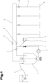
- Fig. 1 shows a schematic of an arrangement according to the invention.
- the arrangement also has an optional feed screw 2, which is connected to a feed silo and conveys the corresponding feed mixture or the individual feed components into a mixing tank with agitator.
- this can alternatively be done manually and/or a series of feed screws 2 can be provided, each of which is connected to a particular feed component, which is mixed in the mixing tank with agitator 1 to form the corresponding finished feed mixture.
- the pump 3 which transports the feed mixture through the arrangement, is arranged downstream of the mixing tank with agitator 1.
- the type of pump 3 can be determined by the specialist for the specific choice of feed mixture, and matched to the corresponding system. Screw displacement pumps, impeller pumps or centrifugal pumps are particularly suitable. Pumps which are frequency-controlled are preferred.
- the pump 3 is connected via a pipe system to a ring line 13 which extends from the feed tank 1 to the feeding stations. There can of course be several ring lines 13.
- the pipe system and the pump 3 are regulated by means of a main valve 4 with respect to this ring line 13.
- An injector also flows into the pipe system, which is arranged downstream of the main valve and comprises a compressed air valve 6 and a water injection valve 5. However, to implement the inventive concept, the supply of one of these two media, compressed air or water, is sufficient.
- These valves are each connected to a corresponding compressed air tank or a compressor and/or a water supply (not shown in the figure).
- the ring line 13 extends from the feed tank 1 to the feeding stations.
- the ring line 13 comprises a flow valve 8 downstream of the pipe system and the pump 3 and the main valve 4. This is followed by a number of outlets, each of which passes through a feeding station valve 10 into a drain pipe 11.
- the drain pipes 11 open into trough bowls 12 with a conical shape in the middle.
- Fig. 1 The four drain pipes 11 shown are purely exemplary in their number and it goes without saying that the number of drain pipes 11 can be scaled by the specialist to the size of the respective system.
- the feeding station valves 10 are located downstream of the feed valve. Further downstream of the feeding station valves 10 is a return valve 9 attached to the ring line 13. The ring line 13 opens at both ends into the mixing tank with agitator 1.
- the pump 3 conveys the feed mass into the ring line 13 via the open main valve 4, whereby when the flow valve 8 is open, the feed is conveyed to the feeding point valves 10 and flows into the trough bowls 12 via the drain pipes 11.
- the main valve 4 is first closed. Then, with the flow valve 8 and return valve 9 open, a water-compressed air mixture is through the ring line 13 so that any residues in the ring line 13 are blown into the mixing tank with agitator 1. To clean the trough bowls 12, the return valve 9 is then closed and the feeding station valves 10 are opened. The compressed air and/or the compressed air-water mixture flows from the ring line 13 via the feeding station valves 10 through the drain pipes 11 to the trough bowls 12.
- the special shape of the trough bowls 12 with their essentially conical elevations pointing towards the mouth of the drain pipe 10 ensures that the trough bowls 12 are optimally blown out.
- Suitable two- or three-way valves for the arrangement according to the invention are known to the person skilled in the art. Solenoid valves or pneumatic valves are particularly suitable.
- the arrangement shown is particularly suitable for the rearing of piglets, pig breeding and pig fattening, where high hygienic requirements exist for the feed supply and the facility.
- FIG. 2 The cleaning effect at the feeding stations is illustrated. Compressed air flows through the ring line 13 through the open feeding station valve 10 through the drain pipe 11 directly onto the central conical elevation of a trough bowl 12 according to the invention. This cleans the bowl bottom of the trough bowl 12 from the resulting air exposure.
- the air contained in the Fig. 2 illustrated trough bowl 12 is shown in cross section.
- the path of the fluid during the cleaning process is in the Fig.2 shown by the arrows.
Landscapes
- Life Sciences & Earth Sciences (AREA)
- Environmental Sciences (AREA)
- Birds (AREA)
- Animal Husbandry (AREA)
- Biodiversity & Conservation Biology (AREA)
- Feeding And Watering For Cattle Raising And Animal Husbandry (AREA)
Description
- Die vorliegende Erfindung betrifft eine Anordnung und ein Verfahren zur Versorgung von Tieren mit Futter, entsprechend den Oberbegriffen der unabhängigen Ansprüche.
- Im Bereich der Tiermast und Aufzucht wird ein Fütterungsverfahren auf der Basis von angemischtem Futter in flüssiger Form verwendet. Bei dieser Art von Fütterung werden in der Regel Mehle, Pflanzenprodukte wie zerkleinertes Gemüse, wie Rüben, Mais und Rohfaserstoffe mit einer Anmischflüssigkeit oder einer anderen nährstoffhaltigen Flüssigkeit, wie zum Beispiel Molke und Milchpulver, gemischt. Der Vorteil einer solchen Flüssigfütterung ist, dass den Tieren die erforderlichen Kalorien, Zusatzstoffe und die notwendige Flüssigkeit in einem Schritt in einer gut und kontrolliert mischbaren und weitgehend homogenen Masse zugeführt werden kann. Die genauen Zusammensetzungen von flüssigen Futtermischungen können je nach Bedarf auf die Tierart, Rasse, Geschlecht, Alter und Gesundheitszustand der Tiere angepasst werden. In den Mastbetrieben wird die Flüssigfütterung in der Regel in Mischbehälter aus Edelstahl durch Anrühren vorbereitet und anschließend mittels einer Druckpumpe durch ein Rohrsystem den Tieren zugeleitet. Diese Anordnungen können zudem weiter mit Steuerelementen ausgestattet sein, welche die notwendige Futtermenge automatisch und in definierten Intervallen zu den Tieren führen. Spezielle Sensoren können außerdem die verabreichte Futtermenge direkt am Trog messen und mittels einer Steuerung kann dafür gesorgt werden, dass ein stetiger Nachschub an Futtermittel besteht. Eine Anordnung gemäß dem Oberbegriff von Anspruch 1 ist aus der
EP0696420A1 bekannt geworden - Durch den hohen Grad an Automatisierung, welche eine Flüssigfutterverabreichung ermöglicht, ergeben sich insbesondere beim Personal erhebliche Einsparungen. Ein Problem bei bestehenden Flüssigfutteranlagen ist aber die Hygiene. Nicht verbrauchtes Futter muss aus den Trögen und den Rohrleitungen entfernt werden, damit es nicht verdirbt und die Gesundheit der Tiere beeinträchtigt. Das Reinigen der Tröge ist allerdings arbeitsintensiv, da die Tröge mindestens einmal am Tag manuell vom alten Futter befreit und gereinigt werden müssen. Dabei wird speziell bei Ferkel in der Regel die gesamte Schale entnommen und gereinigt, oder mit einem Schlauch die Schale abgespritzt. Alternativ gibt es auch Verfahren, bei dem mittels einem Nass- und/oder Trockensaugers die Schale leer gesaugt werden kann. All diesen Verfahren gemeinsam ist allerdings, dass sie einen großen Zeit- und Arbeitsaufwand bedingen.
- Es besteht somit ein Bedürfnis nach Anlagen der eingangs geschilderten Art, welche einen geringeren Wartungsaufwand benötigen. Insbesondere besteht ein Bedürfnis nach Wartungsanlagen, welche ein weitgehend automatisierbares Trogreinigungssystem umfassen.
- Es ist somit eine Aufgabe der vorliegenden Erfindung eine Anordnung zur Versorgung von Tieren mit Futter bereitzustellen, welche mindestens einen Nachteil des Bekannten überwindet, insbesondere welche einen geringeren Reinigungsaufwand aufweist.
- Diese Aufgabe wurde mit einer Anordnung zur Versorgung von Tieren mit Futter gemäß kennzeichnendem Teil des unabhängigen Anspruches gelöst.
- Ein Aspekt der vorliegenden Erfindung betrifft eine Anordnung zur Versorgung von Tieren mit Futter, insbesondere zur Versorgung von Masttieren, besonders bevorzugt Schweinen. Die Anordnung umfasst mindestens einen Futtertank zur Fassung eines Volumens an Futter. Dieser Futtertank ist mit mindestens einer Pumpe wirkverbunden, so dass das Futter aus dem Futtertank in einem Leitungssystem befördert werden kann. Die Anordnung umfasst weiter mindestens eine Ringleitung mit Ringventilen und einer Mehrzahl an Ausläufen. Die Ringleitung ist so angeordnet, dass eine Fluidverbindung zwischen dem Futtertank, dem Leitungssystem und mindestens einer Trogschüssel hergestellt werden kann. Durch diese Fluidverbindung kann im Betrieb das Futter vom Futtertank mittels der Pumpe zu den Trogschüsseln befördert werden. Die Anordnung umfasst weiter ein Ablaufrohr je Ablauf, welches über ein Futterstellenventil mit jeweils einem Ablauf der mindestens einen Ringleitung verbunden ist. Die Anordnung ist dadurch gekennzeichnet, dass das Ablaufrohr im Wesentlichen senkrecht zur Trogschüssel angeordnet ist. Dabei ist die Trogschüssel so ausgestaltet, dass sie eine auf eine Mündung des Ablaufrohres weisende, im Wesentlichen konische Erhebung aufweist.
- Durch die im Wesentlichen konische Erhebung der Trogschüssel kann diese leichter von Futterresten befreit werden, in dem die Spitze des Konus mit einem Reinigungsstrahl beaufschlagt wird.
- Im Sinne der vorliegenden Erfindung sei im Wesentlichen konisch als eine Erhebung zu verstehen, welche sich von einer im Vergleich zur Spitze breiteren Basis hin verjüngt. In einer besonderen Ausführungsform ist die Trogschüssel eine runde Schüssel mit einem äußeren Rand, einem Schüsselboden und einer sich in der Mitte der Schüssel im Wesentlichen konisch nach oben erhebenden Erhebung. Dabei bildet der Schüsselboden einen Ring um die im Wesentlichen konische Erhebung. Die im Wesentlichen konische Erhebung kann in einer Spitze, einer Abrundung oder einer Fläche enden.
- In einer bevorzugten Ausführungsform umfasst der Futtertank mindestens ein Rührwerk zum Anrühren einer Futtermischung.
- Als geeignetes Futter sei im Sinne der vorliegenden Erfindung sämtliche Futtermischungen zu verstehen, welche eine Rheologie aufweisen, die es ihnen gestatten innerhalb der Anordnung, insbesondere den Leitungen, ein fluides Verhalten zu zeigen.
- Das Leitungssystem umfasst auch eine Pressluftzufuhr und/oder eine Wasserzufuhr. Durch die Zufuhr von Pressluft und/oder Wasser kann die entsprechende Beaufschlagung der Trogschüssel stattfinden. Die Zufuhr von Pressluft und/oder Wasser ist durch ein entsprechendes Pressluftventil und/oder Wasserinjektionsventil regelbar.
- Die oben genannte Aufgabe wird mit einem Verfahren der eingangs genannten Art erfindungsgemäß durch die Merkmale des kennzeichnenden Teils von Anspruch 2 gelöst. Beim Verfahren wird in einem ersten Schritt Futtermittel durch einen Futtermitteltank zu einem homogenen Fluid verrührt und über eine Pumpe in eine Ringleitung befördert. Diese Ringleitung mündet in eine Mehrzahl an Trogschüsseln mit mittigen, im Wesentlichen konischen Erhebungen unter den Mündungen. In einem zweiten Schritt wird ein Hauptventil geschlossen und somit die Beförderung des Futtermittels in die Ringleitung unterbunden. Ein Vorlaufventil und ein Rücklaufventil werden geöffnet, sodass ein geschlossener Kreislauf bei geschlossenen Futterstellenventilen mit dem Futtermitteltank und der Ringleitung besteht. Anschließend wird über ein Ventil Pressluft in die Ringleitung geführt. Anschließend wird das Rücklaufventil geschlossen, womit die Pressluft nicht mehr zurück in den Anmischtank strömen kann und die Futterstellenventile geöffnet, sodass die Pressluft aus den Ausläufen ausgetrieben wird, direkt auf die konischen Erhebungen der Trogschüsseln.
- Ein Aspekt der vorliegenden Erfindung betrifft die Verwendung einer eingangs geschilderten Anordnung in der Schweinehaltung, insbesondere der Aufzucht und Fütterung von Ferkeln.
- Zum besseren Verständnis der Erfindung wird diese nun anhand der nachfolgenden Figuren näher erläutert, ohne jedoch auf diese eingeschränkt zu sein. Für einen Fachmann ergeben sich auf der Basis dieser erläuternden Figuren weitere vorteilhafte Ausführungsformen der vorliegenden Erfindung.
- Die Figuren zeigen schematisch:
- Fig. 1
- eine erfindungsgemäße Anordnung für die Zufuhr von Futter an Schweinen, und
- Fig. 2
- die erfindungsgemäßen Trogschüsseln der Anordnung aus der
Fig. 1 . - Einführend sei festgehalten, dass in den unterschiedlich beschriebenen Ausführungsformen gleiche Teile mit gleichen Bezugszeichen bzw. gleichen Bauteilbezeichnungen versehen werden, wobei die in der gesamten Beschreibung enthaltenen Offenbarungen sinngemäß auf gleiche Teile mit gleichen Bezugszeichen bzw. gleichen Bauteilbezeichnungen übertragen werden können. Auch sind die in der Beschreibung gewählten Lageangaben, wie z.B. oben, unten, seitlich usw. auf die unmittelbar beschriebene sowie dargestellte Figur bezogen und sind diese Lageangaben bei einer Lageänderung sinngemäß auf die neue Lage zu übertragen.
-
Fig. 1 zeigt schematisch eine erfindungsgemäße Anordnung. Die Anordnung weist zur besseren Erläuterung auch eine fakultative Zubringerschnecke 2 auf, welche mit einem Futtersilo verbunden ist und jeweils die entsprechende Futtermischung oder die einzelnen Futterbestandteile in einen Anmischtank mit Rührwerk befördert. Selbstverständlich kann dies alternativ händisch geschehen und/oder es kann eine Reihe an Zubringerschnecken 2 vorgesehen sein, welche jeweils mit einem besonderen Futterbestandteil verbunden sind, welcher im Anmischtank mit Rührwerk 1 zur entsprechenden fertigen Futtermischung verrührt wird. - Dem Anmischtank mit Rührwerk 1 nachgeordnet ist die Pumpe 3, welche die Beförderung der Futtermischung durch die Anordnung besorgt. Die Art der Pumpe 3 kann vom Fachmann für die spezifische Wahl der Futtermischung, und abgestimmt auf die entsprechende Anlage gewählt werden. Geeignet sind insbesondere Schneckenverdrängerpumpen, Impellerpumpen oder Kreiselpumpen. Bevorzugt sind Pumpen, welche frequenzgeregelt sind. Die Pumpe 3 ist über ein Leitungssystem mit einer Ringleitung 13 verbunden, welche sich vom Futtertank 1 bis zu den Futterstellen erstreckt. Es können natürlich mehrere Ringleitungen 13 vorhanden sein. Das Leitungssystem und die Pumpe 3 sind mittels eines Hauptventils 4 bezüglich dieser Ringleitung 13 geregelt. In das Leitungssystem mündet weiter ein Injektor, welcher dem Hauptventil nachgeordnet ist und ein Pressluftventil 6 und ein Wasserinjektionsventil 5 umfasst. Für die Ausübung des erfindungsgemäßen Konzeptes reicht aber bereits die Zufuhr eines dieser beiden Medien Pressluft oder Wasser. Diese Ventile sind jeweils mit einem entsprechenden Pressluftbehälter oder einem Kompressor und/oder einer Wasserzufuhr verbunden (in der Figur nicht gezeigt).
- Wie bereits geschildert, erstreckt sich die Ringleitung 13 vom Futtertank 1 bis hin zu den Futterstellen. Dem Leitungssystem und der Pumpe 3 und dem Hauptventil 4 nachgeordnet umfasst die Ringleitung 13 ein Vorlaufventil 8. Diesem folgt eine Mehrzahl an Ausläufen, welche jeweils durch ein Futterstellenventil 10 in ein Ablaufrohr 11 übergehen. Die Ablaufrohre 11 münden in mittig kegelig ausgeführte Trogschüsseln 12. Die in der
Fig. 1 gezeigten vier Ablaufrohre 11 sind rein exemplarisch in ihrer Anzahl und es versteht sich von selbst, dass die Anzahl an Ablaufrohren 11 vom Fachmann an die Größe der jeweiligen Anlage skalierbar ist. - Die Futterstellenventile 10 sind dem Vorlaufventil nachgelagert. Den Futterstellenventilen 10 weiter nachgelagert, ist ein an der Ringleitung 13 angebrachtes Rücklaufventil 9. Die Ringleitung 13 mündet an beiden Enden in den Anmischtank mit Rührwerk 1.
- Im Betrieb fördert die Pumpe 3 über das offene Hauptventil 4 die Futtermasse in die Ringleitung 13, wobei bei offenem Vorlaufventil 8 das Futtermittel zu den Futterstellenventilen 10 gefördert wird und dieses über die Ablaufrohre 11 in die Trogschüsseln 12 mündet.
- Soll die Anordnung gereinigt werden, so wird zunächst das Hauptventil 4 geschlossen. Anschließend wird mit offenem Vorlaufventil 8 und offenem Rücklaufventil 9 ein Wasser-Pressluftgemisch durch die Ringleitung 13 geblasen, so dass allfällige Rückstände in der Ringleitung 13 in den Anmischtank mit Rührwerk 1 geblasen werden. Zur Reinigung der Trogschüsseln 12 wird im Anschluss das Rücklaufventil 9 geschlossen und die Futterstellenventile 10 geöffnet. Die Pressluft und/oder das Pressluft- Wassergemisch strömt von der Ringleitung 13 über die Futterstellenventile 10 durch die Ablaufrohre 11 zu den Trogschüsseln 12. Durch die spezielle Form der Trogschüsseln 12 mit ihren auf die Mündung des Ablaufrohres 10 weisenden, im Wesentlichen konischen Erhebungen werden die Trogschüsseln 12 optimal ausgeblasen.
- Geeignete Zwei- oder Dreiwege-Ventile für die erfindungsgemäße Anordnung sind dem Fachmann bekannt. Insbesondere Magnetventile oder pneumatische Ventile sind geeignet.
- Die gezeigte Anordnung ist besonders für die Aufzucht von Ferkeln, der Schweinezucht und der Schweinemast geeignet, wo hohe hygienische Anforderungen an die Futterversorgung und die Anlage bestehen.
- In der
Fig. 2 ist der Reinigungseffekt an den Futterstellen illustriert. Über die Ringleitung 13 strömt durch das offene Futterstellenventil 10 Pressluft durch das Ablaufrohr 11 direkt auf die mittige konische Erhebung einer erfindungsgemäßen Trogschüssel 12. Dadurch wird der Schalenboden der Trogschüssel 12 von der entstehenden Beaufschlagung mit Luft gereinigt. Die in derFig. 2 illustrierte Trogschüssel 12 ist im Querschnitt gezeigt. - Der Pfad des Fluids während des Reinigungsprozesses ist in der
Fig.2 mittels der Pfeile dargestellt. - Der Ordnung halber sei abschließend darauf hingewiesen, dass zum besseren Verständnis des Aufbaus Elemente teilweise nicht massstabsgetreu und/oder vergrößert und/oder verkleinert dargestellt wurden.
-
- 1
- Futtertank
- 2
- Zubringerschnecke
- 3
- Fütterungspumpe
- 4
- Hauptventil
- 5
- Wasserinjektionsventil
- 6
- Pressluftventil
- 8
- Vorlaufventil
- 9
- Rücklaufventil
- 10
- Futterstellenventil
- 11
- Ablaufrohr
- 12
- Trogschüssel
- 13
- Ringleitung
Claims (2)
- Anordnung zur Versorgung von Tieren mit Futter, umfassend:a) mindestens einen Futtertank (1) zur Fassung eines Volumens an Futter, wobei der Futtertank (1) wirkverbunden ist mit mindestens einer Pumpe (3), zur Beförderung des Futters;b) mindestens eine in den Futtertank (1) mündende Ringleitung (13), mit einem Vorlaufventil (8), einem in einer Austeilrichtung des Futters nach dem Vorlaufventil (8) angeordneten Rücklaufventil (9), und eine Mehrzahl an zwischen dem Vorlaufventil (8) und dem Rücklaufventil (9) angeordneten, Ausläufen für das Futter aufweist, wobei die Ausläufe jeweils über ein Futterstellenventil (10) mit einem in eine Trogschüssel (12) mündenden Ablaufrohr (11) verbunden sind;c) ein Hauptventil (4) zur Regelung der Beförderung des Futters von dem Futtertank (1) in die Ringleitung (13), wobei das Hauptventil (4) der Pumpe (3) nachgeschaltet und dem Vorlaufventil (8) vorgeschaltet ist;d) eine Pressluftzufuhr mit einem Pressluftventil (5) zur Regelung einer Zufuhr von Pressluft in die Ringleitung (13) und/oder eine Wasserzufuhr mit einem Wasserinjektionsventil (6) zur Regelung der Zufuhr von Wasser in die Ringleitung (13), wobei die Pressluftzufuhr und/oder die Wasserzufuhr dem Hauptventil (4) nachgeschaltet und dem Vorlaufventil (8) vorgeschaltet ist,e) wobei bei geöffnetem Vorlaufventil (8), geöffnetem Rücklaufventil (9) und geschlossenem Hauptventil (4) ein Rückstand an Futtermittel bei Durchströmung der Ringleitung (13) mit einem Fluid in den Futtertank (1) geblasen ist;dadurch gekennzeichnet, dass das Ablaufrohr (11) im Wesentlichen senkrecht zur Trogschüssel (12) angeordnet ist und die Trogschüssel (12) eine auf eine Mündung des Ablaufrohres (11) weisende, im Wesentlichen konische Erhebung aufweist, wobei bei geschlossenem Rücklaufventil (9), und geschlossenem Hauptventil (4) und geöffnetem Vorlaufventil (8) sowie geöffnetem Futterstellenventil (10) ein Rückstand an Futtermittel in der Trogschüssel (12) durch Beaufschlagung durch ein Fluid über die Mündung des Ablaufrohres (11) auf die im Wesentlichen konische Erhebung der Trogschüssel (12) aus dieser geblasen ist.
- Verfahren zur Reinigung einer Anordnung zur Versorgung von Tieren mit Futter, gemäß Anspruch 1, umfassend die Schritte:a) Schließen des Hauptventils (4), welches die Zufuhr eines Futtermittels über die Pumpe (3) in der Ringleitung (13) regelt, welche sich von einem Futtertank (1) über die Ausläufe zu einer Mehrzahl an Futterstellen erstreckt, und der Futterstellenventile sowie Öffnen des Vorlaufventils (8) und des Rücklaufventils (9);b) Erstes Durchspülen der Ringleitung (13) mit einem Fluid, so dass Futterreste aus der Ringleitung (13) in den Futtertank (1) geblasen werden;c) Schließen des Rücklaufventils (9) und Öffnen der Futterstellenventile (10);d) Zweites Durchspülen der Ringleitung (13) mit einem Fluid, so dass das Fluid über die Ausläufe in je eine der Trogschüsseln (12) geblasen wird, welche direkt unter dem jeweiligen Auslauf eine im Wesentlichen konische Erhebung aufweist.
Applications Claiming Priority (1)
| Application Number | Priority Date | Filing Date | Title |
|---|---|---|---|
| ATGM50237/2016U AT15761U1 (de) | 2016-11-11 | 2016-11-11 | Futteranlage mit Trogreinigung |
Publications (2)
| Publication Number | Publication Date |
|---|---|
| EP3320771A1 EP3320771A1 (de) | 2018-05-16 |
| EP3320771B1 true EP3320771B1 (de) | 2024-10-02 |
Family
ID=60293823
Family Applications (1)
| Application Number | Title | Priority Date | Filing Date |
|---|---|---|---|
| EP17200629.8A Active EP3320771B1 (de) | 2016-11-11 | 2017-11-08 | Futteranlage mit trogreinigung |
Country Status (2)
| Country | Link |
|---|---|
| EP (1) | EP3320771B1 (de) |
| AT (1) | AT15761U1 (de) |
Families Citing this family (4)
| Publication number | Priority date | Publication date | Assignee | Title |
|---|---|---|---|---|
| US8470012B2 (en) | 2004-09-08 | 2013-06-25 | Arizant Healthcare Inc. | Inflatable convective pad for surgery |
| CN109588333B (zh) * | 2019-01-30 | 2024-03-19 | 柳州鑫兴园农业科技有限公司 | 一种自动喂料系统 |
| CN109769703A (zh) * | 2019-03-21 | 2019-05-21 | 深圳德里克设备有限公司 | 养殖系统及控制方法 |
| AT523747B1 (de) * | 2020-04-24 | 2022-11-15 | Schauer Agrotronic Gmbh | Verfahren zur Fütterung von Tieren und pneumatische Fütterungsanlage |
Family Cites Families (8)
| Publication number | Priority date | Publication date | Assignee | Title |
|---|---|---|---|---|
| HU167180B (de) * | 1971-10-13 | 1975-08-28 | ||
| EP0373147B1 (de) * | 1988-12-07 | 1993-07-14 | Gerhard Dipl.-Ing. Vogl | Verfahren zur Aufbereitung und zur dosierten Abgabe von Mischfutter an mehrere Abgabestellen und Vorrichtung zur Durchführung des Verfahrens |
| AT399439B (de) * | 1992-10-27 | 1995-05-26 | Vogl Gerhard | Verfahren und anlage zur dosierten flüssigfutterausgabe |
| AT400995B (de) * | 1994-08-10 | 1996-05-28 | Vogl Gerhard | Verfahren zur dosierten abgabe von flüssigfutter an mehrere abgabestellen |
| US20090078209A1 (en) * | 2007-09-21 | 2009-03-26 | Matthew Kroeker | Feeding System and Methods Relating to Feeding of Livestock |
| AT506523B1 (de) * | 2008-02-20 | 2011-06-15 | Schauer Maschinenfabrik Gmbh | Anlage zur austeilung von flüssigfutter |
| AT509513B1 (de) * | 2010-03-05 | 2012-09-15 | Schauer Agrotronic Gmbh | Verfahren zur überwachung pneumatisch betätigbarer membranventile in flüssigfütterungsanlagen |
| AT11851U1 (de) * | 2010-03-05 | 2011-06-15 | Schauer Agrotronic Gmbh | Verfahren zur überwachung und regelung einer futterpumpe in flüssigfütterungsanlagen |
-
2016
- 2016-11-11 AT ATGM50237/2016U patent/AT15761U1/de unknown
-
2017
- 2017-11-08 EP EP17200629.8A patent/EP3320771B1/de active Active
Also Published As
| Publication number | Publication date |
|---|---|
| EP3320771A1 (de) | 2018-05-16 |
| AT15761U1 (de) | 2018-05-15 |
Similar Documents
| Publication | Publication Date | Title |
|---|---|---|
| EP0126240B1 (de) | Verfahren und Vorrichtung zum automatischen Füttern grosser Tierbestände, insbesondere von Schweinen | |
| EP3320771B1 (de) | Futteranlage mit trogreinigung | |
| EP2153716B1 (de) | Flüssigfütterungsanlage | |
| EP0595784A1 (de) | Verfahren zur dosierten Abgabe von Flüssigfutter an mehrere Abgabestellen und Anlage zur Durchführung des Verfahrens | |
| WO2010130331A1 (de) | Verrohrungssystem | |
| DE2203556C3 (de) | Verfahren und Vorrichtung für die Fütterung von Schweinen | |
| EP1065925B1 (de) | Verfahren zum ausbringen von nahrungsmittel für tiere und/oder reinigungsmittel aus einem mischbehälter | |
| DE69416542T2 (de) | Vorrichtung zum Melken von Tieren | |
| EP2979543B1 (de) | Flüssigfütterungsanlage für nutztiere | |
| AT400658B (de) | Flüssigfütterungsanlage | |
| EP1425954B1 (de) | Reinigungseinrichtung für ein Entladerohr einer Erntemaschine | |
| DE10047690B4 (de) | Verfahren und Vorrichtung zur Flüssigfütterung von Tieren, insbesondere Jungtieren, wie zum Beispiel Ferkeln | |
| EP3014988B1 (de) | Saugnuckelanordnung für einen Tränkeautomaten | |
| EP0696420B1 (de) | Verfahren zur dosierten Abgabe von Flüssigkeiten an mehrere Abgabestellen | |
| EP1066755A1 (de) | Verfahren und Eirichtung zum Versorgen von Haustieren mit einem flüssigen Nahrungsmittel | |
| EP1203529B1 (de) | Verfahren zum Aufbereiten und dosierten Zuführen von Flüssigfutter | |
| DE19960365C2 (de) | Fütterungsvorrichtung | |
| EP2649876A1 (de) | Vorrichtung und Verfahren zur Abgabe von Feststoffen und Flüssigkeiten an Tiere | |
| EP0956765B1 (de) | Verfahren zur dosierten Abgabe von Futter an mehrere Abgabestellen | |
| DE3149147A1 (de) | "verfahren und vorrichtung zur nasseinlagerung von futtergetreide in einem silo" | |
| DE102013214729A1 (de) | Tankanbindung | |
| DE20111253U1 (de) | Fütterungsanlage, insbesondere für Ferkel | |
| DE102023130682A1 (de) | Vorrichtung und verfahren zur konditionierung von mahlgut | |
| AT402466B (de) | Anlage zur dosierten abgabe von futter an mehrere abgabestellen | |
| DE1607099C3 (de) | Viehfütterungseinrichtung |
Legal Events
| Date | Code | Title | Description |
|---|---|---|---|
| PUAI | Public reference made under article 153(3) epc to a published international application that has entered the european phase |
Free format text: ORIGINAL CODE: 0009012 |
|
| STAA | Information on the status of an ep patent application or granted ep patent |
Free format text: STATUS: THE APPLICATION HAS BEEN PUBLISHED |
|
| AK | Designated contracting states |
Kind code of ref document: A1 Designated state(s): AL AT BE BG CH CY CZ DE DK EE ES FI FR GB GR HR HU IE IS IT LI LT LU LV MC MK MT NL NO PL PT RO RS SE SI SK SM TR |
|
| AX | Request for extension of the european patent |
Extension state: BA ME |
|
| STAA | Information on the status of an ep patent application or granted ep patent |
Free format text: STATUS: REQUEST FOR EXAMINATION WAS MADE |
|
| 17P | Request for examination filed |
Effective date: 20181109 |
|
| RBV | Designated contracting states (corrected) |
Designated state(s): AL AT BE BG CH CY CZ DE DK EE ES FI FR GB GR HR HU IE IS IT LI LT LU LV MC MK MT NL NO PL PT RO RS SE SI SK SM TR |
|
| STAA | Information on the status of an ep patent application or granted ep patent |
Free format text: STATUS: EXAMINATION IS IN PROGRESS |
|
| 17Q | First examination report despatched |
Effective date: 20190415 |
|
| GRAP | Despatch of communication of intention to grant a patent |
Free format text: ORIGINAL CODE: EPIDOSNIGR1 |
|
| STAA | Information on the status of an ep patent application or granted ep patent |
Free format text: STATUS: GRANT OF PATENT IS INTENDED |
|
| INTG | Intention to grant announced |
Effective date: 20240510 |
|
| GRAS | Grant fee paid |
Free format text: ORIGINAL CODE: EPIDOSNIGR3 |
|
| GRAA | (expected) grant |
Free format text: ORIGINAL CODE: 0009210 |
|
| STAA | Information on the status of an ep patent application or granted ep patent |
Free format text: STATUS: THE PATENT HAS BEEN GRANTED |
|
| AK | Designated contracting states |
Kind code of ref document: B1 Designated state(s): AL AT BE BG CH CY CZ DE DK EE ES FI FR GB GR HR HU IE IS IT LI LT LU LV MC MK MT NL NO PL PT RO RS SE SI SK SM TR |
|
| REG | Reference to a national code |
Ref country code: GB Ref legal event code: FG4D Free format text: NOT ENGLISH |
|
| REG | Reference to a national code |
Ref country code: CH Ref legal event code: EP |
|
| REG | Reference to a national code |
Ref country code: IE Ref legal event code: FG4D Free format text: LANGUAGE OF EP DOCUMENT: GERMAN |
|
| REG | Reference to a national code |
Ref country code: DE Ref legal event code: R096 Ref document number: 502017016459 Country of ref document: DE |
|
| P01 | Opt-out of the competence of the unified patent court (upc) registered |
Free format text: CASE NUMBER: APP_60736/2024 Effective date: 20241112 |
|
| PGFP | Annual fee paid to national office [announced via postgrant information from national office to epo] |
Ref country code: DE Payment date: 20241121 Year of fee payment: 8 |
|
| PGFP | Annual fee paid to national office [announced via postgrant information from national office to epo] |
Ref country code: FR Payment date: 20241126 Year of fee payment: 8 |
|
| REG | Reference to a national code |
Ref country code: LT Ref legal event code: MG9D |
|
| REG | Reference to a national code |
Ref country code: NL Ref legal event code: MP Effective date: 20241002 |
|
| PG25 | Lapsed in a contracting state [announced via postgrant information from national office to epo] |
Ref country code: NL Free format text: LAPSE BECAUSE OF FAILURE TO SUBMIT A TRANSLATION OF THE DESCRIPTION OR TO PAY THE FEE WITHIN THE PRESCRIBED TIME-LIMIT Effective date: 20241002 |
|
| PG25 | Lapsed in a contracting state [announced via postgrant information from national office to epo] |
Ref country code: NL Free format text: LAPSE BECAUSE OF FAILURE TO SUBMIT A TRANSLATION OF THE DESCRIPTION OR TO PAY THE FEE WITHIN THE PRESCRIBED TIME-LIMIT Effective date: 20241002 |
|
| PG25 | Lapsed in a contracting state [announced via postgrant information from national office to epo] |
Ref country code: IS Free format text: LAPSE BECAUSE OF FAILURE TO SUBMIT A TRANSLATION OF THE DESCRIPTION OR TO PAY THE FEE WITHIN THE PRESCRIBED TIME-LIMIT Effective date: 20250202 Ref country code: HR Free format text: LAPSE BECAUSE OF FAILURE TO SUBMIT A TRANSLATION OF THE DESCRIPTION OR TO PAY THE FEE WITHIN THE PRESCRIBED TIME-LIMIT Effective date: 20241002 Ref country code: PT Free format text: LAPSE BECAUSE OF FAILURE TO SUBMIT A TRANSLATION OF THE DESCRIPTION OR TO PAY THE FEE WITHIN THE PRESCRIBED TIME-LIMIT Effective date: 20250203 |
|
| PG25 | Lapsed in a contracting state [announced via postgrant information from national office to epo] |
Ref country code: FI Free format text: LAPSE BECAUSE OF FAILURE TO SUBMIT A TRANSLATION OF THE DESCRIPTION OR TO PAY THE FEE WITHIN THE PRESCRIBED TIME-LIMIT Effective date: 20241002 |
|
| PG25 | Lapsed in a contracting state [announced via postgrant information from national office to epo] |
Ref country code: BG Free format text: LAPSE BECAUSE OF FAILURE TO SUBMIT A TRANSLATION OF THE DESCRIPTION OR TO PAY THE FEE WITHIN THE PRESCRIBED TIME-LIMIT Effective date: 20241002 |
|
| PG25 | Lapsed in a contracting state [announced via postgrant information from national office to epo] |
Ref country code: ES Free format text: LAPSE BECAUSE OF FAILURE TO SUBMIT A TRANSLATION OF THE DESCRIPTION OR TO PAY THE FEE WITHIN THE PRESCRIBED TIME-LIMIT Effective date: 20241002 |
|
| PG25 | Lapsed in a contracting state [announced via postgrant information from national office to epo] |
Ref country code: NO Free format text: LAPSE BECAUSE OF FAILURE TO SUBMIT A TRANSLATION OF THE DESCRIPTION OR TO PAY THE FEE WITHIN THE PRESCRIBED TIME-LIMIT Effective date: 20250102 |
|
| PG25 | Lapsed in a contracting state [announced via postgrant information from national office to epo] |
Ref country code: LV Free format text: LAPSE BECAUSE OF FAILURE TO SUBMIT A TRANSLATION OF THE DESCRIPTION OR TO PAY THE FEE WITHIN THE PRESCRIBED TIME-LIMIT Effective date: 20241002 Ref country code: GR Free format text: LAPSE BECAUSE OF FAILURE TO SUBMIT A TRANSLATION OF THE DESCRIPTION OR TO PAY THE FEE WITHIN THE PRESCRIBED TIME-LIMIT Effective date: 20250103 |
|
| PG25 | Lapsed in a contracting state [announced via postgrant information from national office to epo] |
Ref country code: PL Free format text: LAPSE BECAUSE OF FAILURE TO SUBMIT A TRANSLATION OF THE DESCRIPTION OR TO PAY THE FEE WITHIN THE PRESCRIBED TIME-LIMIT Effective date: 20241002 Ref country code: CZ Free format text: LAPSE BECAUSE OF FAILURE TO SUBMIT A TRANSLATION OF THE DESCRIPTION OR TO PAY THE FEE WITHIN THE PRESCRIBED TIME-LIMIT Effective date: 20241002 |
|
| PG25 | Lapsed in a contracting state [announced via postgrant information from national office to epo] |
Ref country code: RS Free format text: LAPSE BECAUSE OF FAILURE TO SUBMIT A TRANSLATION OF THE DESCRIPTION OR TO PAY THE FEE WITHIN THE PRESCRIBED TIME-LIMIT Effective date: 20250102 |
|
| REG | Reference to a national code |
Ref country code: CH Ref legal event code: PL |
|
| PG25 | Lapsed in a contracting state [announced via postgrant information from national office to epo] |
Ref country code: SM Free format text: LAPSE BECAUSE OF FAILURE TO SUBMIT A TRANSLATION OF THE DESCRIPTION OR TO PAY THE FEE WITHIN THE PRESCRIBED TIME-LIMIT Effective date: 20241002 |
|
| REG | Reference to a national code |
Ref country code: DE Ref legal event code: R097 Ref document number: 502017016459 Country of ref document: DE |
|
| PG25 | Lapsed in a contracting state [announced via postgrant information from national office to epo] |
Ref country code: MC Free format text: LAPSE BECAUSE OF FAILURE TO SUBMIT A TRANSLATION OF THE DESCRIPTION OR TO PAY THE FEE WITHIN THE PRESCRIBED TIME-LIMIT Effective date: 20241002 |
|
| PG25 | Lapsed in a contracting state [announced via postgrant information from national office to epo] |
Ref country code: DK Free format text: LAPSE BECAUSE OF FAILURE TO SUBMIT A TRANSLATION OF THE DESCRIPTION OR TO PAY THE FEE WITHIN THE PRESCRIBED TIME-LIMIT Effective date: 20241002 |
|
| PG25 | Lapsed in a contracting state [announced via postgrant information from national office to epo] |
Ref country code: LU Free format text: LAPSE BECAUSE OF NON-PAYMENT OF DUE FEES Effective date: 20241108 |
|
| REG | Reference to a national code |
Ref country code: CH Ref legal event code: PL |
|
| PG25 | Lapsed in a contracting state [announced via postgrant information from national office to epo] |
Ref country code: EE Free format text: LAPSE BECAUSE OF FAILURE TO SUBMIT A TRANSLATION OF THE DESCRIPTION OR TO PAY THE FEE WITHIN THE PRESCRIBED TIME-LIMIT Effective date: 20241002 |
|
| PG25 | Lapsed in a contracting state [announced via postgrant information from national office to epo] |
Ref country code: CH Free format text: LAPSE BECAUSE OF NON-PAYMENT OF DUE FEES Effective date: 20241130 |
|
| PG25 | Lapsed in a contracting state [announced via postgrant information from national office to epo] |
Ref country code: RO Free format text: LAPSE BECAUSE OF FAILURE TO SUBMIT A TRANSLATION OF THE DESCRIPTION OR TO PAY THE FEE WITHIN THE PRESCRIBED TIME-LIMIT Effective date: 20241002 |
|
| PG25 | Lapsed in a contracting state [announced via postgrant information from national office to epo] |
Ref country code: SK Free format text: LAPSE BECAUSE OF FAILURE TO SUBMIT A TRANSLATION OF THE DESCRIPTION OR TO PAY THE FEE WITHIN THE PRESCRIBED TIME-LIMIT Effective date: 20241002 |
|
| PG25 | Lapsed in a contracting state [announced via postgrant information from national office to epo] |
Ref country code: IT Free format text: LAPSE BECAUSE OF FAILURE TO SUBMIT A TRANSLATION OF THE DESCRIPTION OR TO PAY THE FEE WITHIN THE PRESCRIBED TIME-LIMIT Effective date: 20241002 |
|
| PLBE | No opposition filed within time limit |
Free format text: ORIGINAL CODE: 0009261 |
|
| STAA | Information on the status of an ep patent application or granted ep patent |
Free format text: STATUS: NO OPPOSITION FILED WITHIN TIME LIMIT |
|
| REG | Reference to a national code |
Ref country code: BE Ref legal event code: MM Effective date: 20241130 |
|
| PG25 | Lapsed in a contracting state [announced via postgrant information from national office to epo] |
Ref country code: SE Free format text: LAPSE BECAUSE OF FAILURE TO SUBMIT A TRANSLATION OF THE DESCRIPTION OR TO PAY THE FEE WITHIN THE PRESCRIBED TIME-LIMIT Effective date: 20241002 |
|
| 26N | No opposition filed |
Effective date: 20250703 |
|
| GBPC | Gb: european patent ceased through non-payment of renewal fee |
Effective date: 20250102 |
|
| PG25 | Lapsed in a contracting state [announced via postgrant information from national office to epo] |
Ref country code: BE Free format text: LAPSE BECAUSE OF NON-PAYMENT OF DUE FEES Effective date: 20241130 Ref country code: GB Free format text: LAPSE BECAUSE OF NON-PAYMENT OF DUE FEES Effective date: 20250102 |
|
| PG25 | Lapsed in a contracting state [announced via postgrant information from national office to epo] |
Ref country code: IE Free format text: LAPSE BECAUSE OF NON-PAYMENT OF DUE FEES Effective date: 20241108 |