EP3320325B1 - Differential viscometer with solvent compressibility correction - Google Patents
Differential viscometer with solvent compressibility correction Download PDFInfo
- Publication number
- EP3320325B1 EP3320325B1 EP16822077.0A EP16822077A EP3320325B1 EP 3320325 B1 EP3320325 B1 EP 3320325B1 EP 16822077 A EP16822077 A EP 16822077A EP 3320325 B1 EP3320325 B1 EP 3320325B1
- Authority
- EP
- European Patent Office
- Prior art keywords
- arm
- volume
- capillary
- bridge
- capillaries
- Prior art date
- Legal status (The legal status is an assumption and is not a legal conclusion. Google has not performed a legal analysis and makes no representation as to the accuracy of the status listed.)
- Active
Links
Images


Classifications
-
- G—PHYSICS
- G01—MEASURING; TESTING
- G01N—INVESTIGATING OR ANALYSING MATERIALS BY DETERMINING THEIR CHEMICAL OR PHYSICAL PROPERTIES
- G01N11/00—Investigating flow properties of materials, e.g. viscosity, plasticity; Analysing materials by determining flow properties
- G01N11/02—Investigating flow properties of materials, e.g. viscosity, plasticity; Analysing materials by determining flow properties by measuring flow of the material
- G01N11/04—Investigating flow properties of materials, e.g. viscosity, plasticity; Analysing materials by determining flow properties by measuring flow of the material through a restricted passage, e.g. tube, aperture
- G01N11/08—Investigating flow properties of materials, e.g. viscosity, plasticity; Analysing materials by determining flow properties by measuring flow of the material through a restricted passage, e.g. tube, aperture by measuring pressure required to produce a known flow
-
- G—PHYSICS
- G01—MEASURING; TESTING
- G01N—INVESTIGATING OR ANALYSING MATERIALS BY DETERMINING THEIR CHEMICAL OR PHYSICAL PROPERTIES
- G01N30/00—Investigating or analysing materials by separation into components using adsorption, absorption or similar phenomena or using ion-exchange, e.g. chromatography or field flow fractionation
- G01N30/02—Column chromatography
- G01N30/62—Detectors specially adapted therefor
-
- G—PHYSICS
- G01—MEASURING; TESTING
- G01N—INVESTIGATING OR ANALYSING MATERIALS BY DETERMINING THEIR CHEMICAL OR PHYSICAL PROPERTIES
- G01N30/00—Investigating or analysing materials by separation into components using adsorption, absorption or similar phenomena or using ion-exchange, e.g. chromatography or field flow fractionation
- G01N30/02—Column chromatography
- G01N30/26—Conditioning of the fluid carrier; Flow patterns
- G01N30/28—Control of physical parameters of the fluid carrier
- G01N30/32—Control of physical parameters of the fluid carrier of pressure or speed
-
- G—PHYSICS
- G01—MEASURING; TESTING
- G01N—INVESTIGATING OR ANALYSING MATERIALS BY DETERMINING THEIR CHEMICAL OR PHYSICAL PROPERTIES
- G01N30/00—Investigating or analysing materials by separation into components using adsorption, absorption or similar phenomena or using ion-exchange, e.g. chromatography or field flow fractionation
- G01N30/02—Column chromatography
- G01N30/62—Detectors specially adapted therefor
- G01N30/64—Electrical detectors
-
- G—PHYSICS
- G01—MEASURING; TESTING
- G01N—INVESTIGATING OR ANALYSING MATERIALS BY DETERMINING THEIR CHEMICAL OR PHYSICAL PROPERTIES
- G01N30/00—Investigating or analysing materials by separation into components using adsorption, absorption or similar phenomena or using ion-exchange, e.g. chromatography or field flow fractionation
- G01N30/02—Column chromatography
- G01N30/62—Detectors specially adapted therefor
- G01N2030/621—Detectors specially adapted therefor signal-to-noise ratio
- G01N2030/625—Detectors specially adapted therefor signal-to-noise ratio by measuring reference material, e.g. carrier without sample
-
- G—PHYSICS
- G01—MEASURING; TESTING
- G01N—INVESTIGATING OR ANALYSING MATERIALS BY DETERMINING THEIR CHEMICAL OR PHYSICAL PROPERTIES
- G01N30/00—Investigating or analysing materials by separation into components using adsorption, absorption or similar phenomena or using ion-exchange, e.g. chromatography or field flow fractionation
- G01N30/02—Column chromatography
- G01N30/62—Detectors specially adapted therefor
- G01N2030/626—Detectors specially adapted therefor calibration, baseline
-
- G—PHYSICS
- G01—MEASURING; TESTING
- G01N—INVESTIGATING OR ANALYSING MATERIALS BY DETERMINING THEIR CHEMICAL OR PHYSICAL PROPERTIES
- G01N30/00—Investigating or analysing materials by separation into components using adsorption, absorption or similar phenomena or using ion-exchange, e.g. chromatography or field flow fractionation
- G01N30/02—Column chromatography
- G01N30/26—Conditioning of the fluid carrier; Flow patterns
Definitions
- a pump 101 draws fluid from a reservoir 102 and passes it through a sensing capillary 103.
- a differential transducer 104 measures the pressure across the capillary. The measured pressure is proportional to the flow rate and the sample viscosity.
- a problem arising from such a flowing system is that if the pump is not perfectly stable, pressure pulses appear identical to changes in the sample viscosity. Since the output of the conventional viscometer is directly proportional to the pressure, the sensitivity of such a device is limited by the quality of the pump used. High quality chromatography solvent delivery systems commonly provide solvent with pressure pulses less than 0.1 %, so the ability to measure specific viscosity is limited to this level.
- capillary bridge viscometer such as that described by Haney in 1982 in U.S. Patent No. 4,463,598 .
- the capillary bridge viscometer is a fluid analog of the classical Wheatstone bridge electrical circuit in which four capillaries are connected in a bridge formation along with a large fluid reservoir in one of the lower bridge arms.
- the delay volume insures that the bridge will go out of balance when a sample is introduced to the bridge. Data can be taken until the sample emerges from the delay column at which time one must wait for the column to refill with solvent before another sample may be injected.
- the out-of balance pressure is measured by a differential pressure transducer (DP), and the pressure from top to bottom of the bridge is measured by a separate transducer (IP).
- DP differential pressure transducer
- IP separate transducer
- the IP transducer experiences no such cancellation.
- the bridge appears to be two series capillaries of impedance R (the left side of the bridge) in parallel with two series capillaries of impedance R (the right side of the bridge).
- the resulting circuit as seen by the IP transducer is simply a single capillary of impedance R. Therefore the IP transducer acts, for all intents and purposes, as a single capillary viscometer, with all of the problems of pump pulse pickup.
- Figure 4 presents data from a single capillary viscometer taken from a chromatographic elution of Bovine Serum Albumin (BSA) fractionated by a size exclusion column.
- BSA Bovine Serum Albumin
- the DP signal 401 is nearly free of pump pulses, whereas the IP signal 402 is not.
- the primary problem with the strong pump pulse reduction seen in Fig. 4 is that much of the benefit seen is not due to bridge cancellation. Instead pump pulses are suppressed because the DP sensor has a very slow time constant ( ⁇ 9 seconds) and is acting as a low pass filter, thus not offering the advantage of high resolution one expects from a high quality viscometer.
- the time constant of the sensors in the system can be determined by performing a simple experiment.
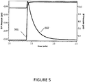
- Figure 5 shows the response of the instrument to a rapid change in the applied flow rate from 0.5ml/min to 1.0 ml/min.
- the IP signal 501 jumps from 5.5psi to 1 1psi as expected, and equilibrates to the new valve with a time constant around 0.5 seconds.
- the DP signal 502 in contrast, has an initial perturbation and equilibrates to a new equilibrium value with a 9 second time constant.
- the low pass filtering that occurs from slow sensors works well to eliminate pulses when the pressure oscillations are much faster than the characteristic time scale of the underlying peak.
- a standard ViscoStar® II viscometer (Wyatt Technology Corporation, Santa Barbara, California) equipped with a Validyne pressure transducer (Validyne Engineering, Northridge, California) was used to measure a sample peak.
- the peak consisted of 100 ⁇ l of 2mg/ml BSA injected directly into the viscometer.
- the flow rate was 0.6667ml/min.
- the viscometer was configured with only the short delay column to reduce the sample runs to only a few minutes.
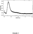
- FIG. 7 shows data taken with the same system configured with DP86 transducers (Measurement Specialties, Fremont, California). Measurements showed that these transducers have a time constant around 0.2 seconds in this system. As seen in Fig. 7 , the pump pulses are very obvious. Therefore it can be deduced that the pulses were always present, but the Validyne transducers, because of their slow response, were suppressing them.
- Max A. Haney "The differential viscometer. II. On-line viscosity detector for size-exclusion chromatography", Journal of Applied Polymer Science, July 1985 (1985-07), pages 3037-3049, XP055554766 , discloses a capillary bridge viscometer comprising a holdup reservoir (A) located to a position out of the flow stream and that acts as a compensation volume so that any temperature fluctuations cause equal volume changes on each side of the differential pressure transducer.
- A holdup reservoir
- a capillary bridge viscometer as defined in claim 1.
- a novel modification to conventional viscometric measurement systems can correct the time constant mismatch that is inherent to conventional capillary bridge designs.
- An additional volume is added to the system which compensates for the pump pulses which traditionally limit the possible sensitivity of measurements.
- the amplitude suppression ratio is defined as: .. (3) where IPA is the amplitude of the pump pulses as measured by the IP transducer, and DPA is the amplitude of pulses measured by DP transducer.
- FIG 9 shows the IP 901 signal plotted on the right axis and the DP signal 902 plotted on the left axis.
- the solvent was PBS flowing at 0.6667ml/min pumped by a Shimadzu LC-20AD solvent delivery module (Shimadzu Corporation, Kyoto, Japan).
- the pump was stabilized by flowing the solvent through 10ft of 0.005"ID polyether ether ketone (PEEK) tubing before it flowed into the viscometer. This creates about 1000psi back-pressure on the pump.
- PEEK polyether ether ketone
- SR ⁇ IP ⁇ / DP ⁇
- IP ( ⁇ ) and DP ( ⁇ ) are the Fourier Transforms of IP ( t ) and DP ( t ) respectively.
- SR ( ⁇ 0 ) the fundamental pump frequency
- the delay columns are designed to have a large internal volume, but a vanishingly small flow impedance. This is accomplished by filling columns with large diameter beads. Because the interstices are large, the flow impedance is very low.
- the ViscoStar viscometer (Wyatt Technology Corporation, Santa Barbara, California), for example, uses 0.4mm diameter ZrSiO2 beads. The open space accessible to the sample fluid is 8.1ml. This can be compared to the individual capillaries, which are 0.25mm ID and 660 mm long with an internal volume of 33 ⁇ l. The pressure drop across the delay volume is less than 1% of the pressure drop across the measurement capillaries.
- the bridge is balanced with the columns installed so that the pressure drop across the DP transducer is adjusted to nearly zero when there is pure solvent flowing.
- the pressure drop across the column has a negligible effect on the calculation of the specific viscosity, although as will be argued below the delay volume plays an unexpected role in limiting the ability of the bridge to cancel pump pulses.
- the bridge is essentially symmetric. Both sides of the DP transducer should see pump pulses equally. Since DP is a differential sensor, any common mode signal, such as the pump pulses, will cancel and the suppression ratio should diverge. The actual suppression ratio is around 17. So the question must be asked, why are pump pulses not better cancelled?
- the pump pulses are positively correlated with the signal seen by the IP transducer.
- the IP signal is high, the DP signal is also high.
- the bridge were truly symmetric, there would be nothing to distinguish the DP+ side from the DP- side.
- One would expect any given realization of the bridge would sometimes be positively correlated and sometimes negatively correlated, but this is not the case; they are always positively correlated.
- the DP transducer is reversed (with the + and - sides ports switched) the effect reverses. This implies that the side that is opposite of the delay column is correlated with the IP.
- the effect is persistent showing that the effect is not somehow being generated inside the transducer.
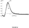
- Fig. 10 shows the change in the baseline when the flow rate is abruptly changed from 0.5ml/min to 0.6667ml/min.
- the IP transducer signal 1001 increases smoothly from around 5.4psi to 7.2psi.
- the time scale for this change is presumably from a combination of how quickly the pump was able to change the flow rate, and the time constant of the transducer. More interesting is what happens to the DP signal 1002.
- the baseline changes from 0.051psi to 0.060psi. If the four bridge capillaries were perfectly matched, the baseline would be zero for all flow rates. If this system is slightly out of balance, as is the case here, the change in the baseline is proportional to the applied flow rate. However the salient point is that the signal overshoots the new baseline. Consider the implications that this has for flow in the bridge.
- Figure 11 presents a simple model of the pressure change on either side of the DP transducer 1101.
- the absolute pressure on both sides of the DP transducer 1101 must increase.
- DP _ ( t ) 1102 the pressure on the positive side as DP + ( t ) 1103.
- DP ( t ) DP + ( t ) -DP_ ( t ) is larger than its final equilibrium value. Therefore the pressure on the positive 1103 side of the transducer is higher than on the negative side 1102.
- the implication therefore is that the pressure difference, and therefore the flow rate, on the upper left capillary 1104 is higher than on the upper right capillary 1105.
- Fig. 11 This is denoted in Fig. 11 by the thickness of the lined arrows.
- the flow through the lower left capillary 1106 after the delay volume 1107 is lower than through the lower right capillary 1108.
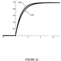
- Fig. 12 Schematically the pressure of the two sides of the bridge are shown in Fig. 12 by the traces of DP +( t ) 1201 and DP - ( t ) 1202.
- the difference between the two signals shown in Fig. 12 has an overshoot that is shown in Fig. 13 .
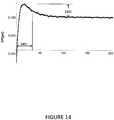
- the data shown in Fig. 10 can be fit a model including an offset to represent the imperfect bridge balance.
- the result is shown in Fig. 14 .
- the time scale of the overshoot 1401 is approximately 3 seconds and the amplitude 1402 is 0.004psi.
- ⁇ v is the change in volume
- ⁇ p is the change in pressure
- d is the inner diameter of the tube
- T is the wall thickness
- E Young's Modulus
- v Poisson's ratio
- the pulse compensation (PC) volume 1501 cannot be put in series with the measurement capillaries or it would affect the viscosity measurement. By putting it between DP+ 1502 and the T-union 1503 connecting R2 and R4, none of the sample passes through it. It simply transmits the pressure to the sensor. One can adjust the volume in PC until it matches that from the delay columns 1504. When the valves V2 and V3 are actuated (DP Purge), the PC volume 1501 is flushed along with the interior of the DP transducer. One does not have to put the PC in series with the transducer; one could equally well put it on a separate T connection between R2 and R4, but in this location it would require an additional valve to flush it and eliminate bubbles and trapped fluid.
- the PC could take the form of a delay column like that in the left arm but since the sample never flows through PC a long length of capillary works as well. Indeed using a long length of capillary tubing is less expensive and more compact.
- Figure 16 shows the effect of varying the length of 0.050" ID capillary tubing used as the PC volume.
- the suppression ratio grows until it reaches a maximum around 23ft, at which point the volume of the PC is 8.4mL.
- the delay columns on the lower left side of the bridge have an aggregate interior volume of 22.5mL, but they are filled with a packed powder of spherical beads.
- the peak suppression ratio occurs when the PC volume matches the open space in the delay volumes.
- the peak suppression ratio is nearly two orders of magnitude higher than the standard bridge, and the parasitic noise from pump pulses is essentially eliminated. This is a primary goal of this invention.
- the improved design increases the system sensitivity while simultaneously allowing for the use of less expensive pumps.
- FIG. 17 shows the result of measuring the suppression ratio as a function of tubing length in aqueous solutions. The peak in the curve corresponds to a 17ft length of 0.030" ID PEEK tubing. The interior volume is 2.4mL compared to 8.4mL that was required when using stainless steel capillary. As expected when one uses softer tubing, the solvent compressibility is balanced with a much lower volume.
- the four capillary bridge viscometer has been used for years as an on-line chromatography detector. However many researchers have suffered with limited sensitivity due to pick-up from pump pulses and other parasitic noise sources. Until now, the fundamental promise of the bridge design to reject pump pulses has only partially been realized. With this innovative and inexpensive improvement to the bridge design, one can enhance the sensitivity to low concentration, low viscosity samples and continue to achieve high quality data even when using inexpensive pumps.
Landscapes
- General Health & Medical Sciences (AREA)
- Health & Medical Sciences (AREA)
- Life Sciences & Earth Sciences (AREA)
- Chemical & Material Sciences (AREA)
- Analytical Chemistry (AREA)
- Biochemistry (AREA)
- Physics & Mathematics (AREA)
- General Physics & Mathematics (AREA)
- Immunology (AREA)
- Pathology (AREA)
- Treatment Of Liquids With Adsorbents In General (AREA)
- Measuring Fluid Pressure (AREA)
- Sampling And Sample Adjustment (AREA)
Applications Claiming Priority (2)
| Application Number | Priority Date | Filing Date | Title |
|---|---|---|---|
| US201562190171P | 2015-07-08 | 2015-07-08 | |
| PCT/US2016/041649 WO2017008062A1 (en) | 2015-07-08 | 2016-07-08 | Differential viscometer with solvent compressibility correction |
Publications (3)
| Publication Number | Publication Date |
|---|---|
| EP3320325A1 EP3320325A1 (en) | 2018-05-16 |
| EP3320325A4 EP3320325A4 (en) | 2019-03-20 |
| EP3320325B1 true EP3320325B1 (en) | 2021-03-24 |
Family
ID=57685891
Family Applications (1)
| Application Number | Title | Priority Date | Filing Date |
|---|---|---|---|
| EP16822077.0A Active EP3320325B1 (en) | 2015-07-08 | 2016-07-08 | Differential viscometer with solvent compressibility correction |
Country Status (5)
| Country | Link |
|---|---|
| US (2) | US10697878B2 (https=) |
| EP (1) | EP3320325B1 (https=) |
| JP (1) | JP6887413B2 (https=) |
| CN (1) | CN107709963B (https=) |
| WO (1) | WO2017008062A1 (https=) |
Families Citing this family (3)
| Publication number | Priority date | Publication date | Assignee | Title |
|---|---|---|---|---|
| US10712321B2 (en) | 2016-11-02 | 2020-07-14 | Wyatt Technology Corporation | Method to eliminate periodic noise from data collected with a chromatography system |
| CN111665168B (zh) * | 2019-03-07 | 2023-05-23 | 中国石油化工股份有限公司 | 压力脉冲条件下流体粘度的检测装置及方法 |
| CN116754436A (zh) * | 2023-06-21 | 2023-09-15 | 上海孚凌自动化控制系统股份有限公司 | 粘度计检测标定装置 |
Family Cites Families (12)
| Publication number | Priority date | Publication date | Assignee | Title |
|---|---|---|---|---|
| US3808877A (en) * | 1972-09-18 | 1974-05-07 | Du Pont | Capillary viscometer |
| GB1566154A (en) * | 1976-03-27 | 1980-04-30 | Weber G | Method of measuring the fluidity of liquids for medical and pharmaceutical pruposes and apparatus for performing the method |
| US4463598A (en) * | 1982-12-10 | 1984-08-07 | Haney Max A | Capillary bridge viscometer |
| JPH06100525B2 (ja) * | 1985-10-18 | 1994-12-12 | 東洋紡績株式会社 | 細管式粘度計 |
| US20030203504A1 (en) * | 2002-04-26 | 2003-10-30 | John Hefti | Diffusion-based system and method for detecting and monitoring activity of biologic and chemical species |
| US7213439B2 (en) * | 2005-03-28 | 2007-05-08 | Wyatt Technology Corporation | Automatic bridge balancing means and method for a capillary bridge viscometer |
| US7331218B2 (en) * | 2005-09-23 | 2008-02-19 | Wyatt Technology Corporation | Capillary bridge viscometer and method for measuring specific viscosity |
| US7334457B2 (en) * | 2005-10-12 | 2008-02-26 | Viscotek Corporation | Multi-capillary viscometer system and method |
| US7594428B2 (en) | 2005-10-12 | 2009-09-29 | Viscotek Corporation | Apparatus and method for eliminating the breakthrough peak in differential detectors |
| JP5200507B2 (ja) * | 2007-11-30 | 2013-06-05 | 東ソー株式会社 | 液体クロマトグラフ用粘度計 |
| JP2013537975A (ja) * | 2010-09-23 | 2013-10-07 | マルバーン インストゥルメンツ インコーポレイテッド | 平衡化毛細管ブリッジ粘度計 |
| US8997555B2 (en) * | 2013-01-07 | 2015-04-07 | Flowpro Well Technology a.s. | System and method for generating a change in pressure proportional to fluid viscosity |
-
2016
- 2016-07-08 CN CN201680037147.5A patent/CN107709963B/zh active Active
- 2016-07-08 EP EP16822077.0A patent/EP3320325B1/en active Active
- 2016-07-08 WO PCT/US2016/041649 patent/WO2017008062A1/en not_active Ceased
- 2016-07-08 US US15/736,291 patent/US10697878B2/en active Active
- 2016-07-08 JP JP2018500442A patent/JP6887413B2/ja active Active
-
2020
- 2020-06-30 US US16/917,831 patent/US11674873B2/en active Active
Non-Patent Citations (1)
| Title |
|---|
| None * |
Also Published As
| Publication number | Publication date |
|---|---|
| WO2017008062A1 (en) | 2017-01-12 |
| JP6887413B2 (ja) | 2021-06-16 |
| US20180188146A1 (en) | 2018-07-05 |
| CN107709963A (zh) | 2018-02-16 |
| US20200333231A1 (en) | 2020-10-22 |
| EP3320325A4 (en) | 2019-03-20 |
| JP2018519529A (ja) | 2018-07-19 |
| EP3320325A1 (en) | 2018-05-16 |
| CN107709963B (zh) | 2021-04-30 |
| US10697878B2 (en) | 2020-06-30 |
| US11674873B2 (en) | 2023-06-13 |
Similar Documents
| Publication | Publication Date | Title |
|---|---|---|
| US11674873B2 (en) | Differential viscometer with solvent compressibility correction | |
| RU2718738C1 (ru) | Устройство и способ динамической калибровки датчиков давления | |
| US7406387B2 (en) | Apparatus and method for detecting blockage of impulse lines | |
| Page et al. | Pore-space correlations in capillary condensation in Vycor | |
| NO20060885L (no) | Anordning og fremgangsmate for kompensering av en Coriolis-maler | |
| NO334153B1 (no) | Nede-i-hulls densitometer | |
| JP2006284556A (ja) | ピストン移動の補正を伴う溶剤供給 | |
| RU2758193C1 (ru) | Способ и устройство для регулировки измерения фазовой доли и концентрации расходомера | |
| CA2486732A1 (en) | Probe for measuring parameters of a flowing fluid and/or multiphase mixture | |
| KR20130009611A (ko) | 도압관의 클로깅 진단 시스템 및 진단 방법 | |
| US8910524B2 (en) | Linked bridge pressure transducer assemblies | |
| DE10335665A1 (de) | Massendurchflussmessgerät | |
| US20170016793A1 (en) | Systems and methods for liquid dynamic pressure testing | |
| Ma et al. | High-sampled structural displacement estimation through the FIR filter-based two-stage fusion of high-sampled acceleration and temporally aliased low-sampled displacement measurements | |
| JP2009511918A (ja) | 改良された多毛細管粘度計装置および方法 | |
| US7260496B2 (en) | Pressure detector and method of diagnosing blockage of impulse lines | |
| Han et al. | Velocity, density and modulus of hydrocarbon fluids--data measurement | |
| CN114296150B (zh) | 一种阵列侧向仪器的加速度校正方法及校正装置 | |
| JPH0843167A (ja) | 液体試薬の容積測定方法 | |
| CN115541152A (zh) | 测量方法、测量装置、测量系统及存储介质 | |
| JPH08101158A (ja) | 流動電位測定法 | |
| Bunce et al. | Case study: calculating bridge displacement from accelerations for load assessment calculations | |
| SU1430511A1 (ru) | Устройство дл определени водонефт ного контакта в скважинах | |
| US20250297889A1 (en) | Measurement Method, Measurement Apparatus, Measurement System, And Non-Transitory Computer-Readable Storage Medium Storing Measurement Program | |
| CN115541151A (zh) | 测量方法、测量装置、测量系统以及测量程序 |
Legal Events
| Date | Code | Title | Description |
|---|---|---|---|
| STAA | Information on the status of an ep patent application or granted ep patent |
Free format text: STATUS: THE INTERNATIONAL PUBLICATION HAS BEEN MADE |
|
| TPAC | Observations filed by third parties |
Free format text: ORIGINAL CODE: EPIDOSNTIPA |
|
| PUAI | Public reference made under article 153(3) epc to a published international application that has entered the european phase |
Free format text: ORIGINAL CODE: 0009012 |
|
| STAA | Information on the status of an ep patent application or granted ep patent |
Free format text: STATUS: REQUEST FOR EXAMINATION WAS MADE |
|
| 17P | Request for examination filed |
Effective date: 20180208 |
|
| AK | Designated contracting states |
Kind code of ref document: A1 Designated state(s): AL AT BE BG CH CY CZ DE DK EE ES FI FR GB GR HR HU IE IS IT LI LT LU LV MC MK MT NL NO PL PT RO RS SE SI SK SM TR |
|
| AX | Request for extension of the european patent |
Extension state: BA ME |
|
| DAV | Request for validation of the european patent (deleted) | ||
| DAX | Request for extension of the european patent (deleted) | ||
| RIN1 | Information on inventor provided before grant (corrected) |
Inventor name: TRAINOFF, STEVEN |
|
| A4 | Supplementary search report drawn up and despatched |
Effective date: 20190220 |
|
| RIC1 | Information provided on ipc code assigned before grant |
Ipc: G01N 11/04 20060101AFI20190214BHEP Ipc: G01N 30/62 20060101ALI20190214BHEP Ipc: G01N 21/41 20060101ALI20190214BHEP Ipc: G01N 30/02 20060101ALI20190214BHEP Ipc: G01N 11/08 20060101ALI20190214BHEP |
|
| GRAP | Despatch of communication of intention to grant a patent |
Free format text: ORIGINAL CODE: EPIDOSNIGR1 |
|
| STAA | Information on the status of an ep patent application or granted ep patent |
Free format text: STATUS: GRANT OF PATENT IS INTENDED |
|
| INTG | Intention to grant announced |
Effective date: 20201007 |
|
| GRAS | Grant fee paid |
Free format text: ORIGINAL CODE: EPIDOSNIGR3 |
|
| GRAA | (expected) grant |
Free format text: ORIGINAL CODE: 0009210 |
|
| STAA | Information on the status of an ep patent application or granted ep patent |
Free format text: STATUS: THE PATENT HAS BEEN GRANTED |
|
| AK | Designated contracting states |
Kind code of ref document: B1 Designated state(s): AL AT BE BG CH CY CZ DE DK EE ES FI FR GB GR HR HU IE IS IT LI LT LU LV MC MK MT NL NO PL PT RO RS SE SI SK SM TR |
|
| REG | Reference to a national code |
Ref country code: GB Ref legal event code: FG4D |
|
| REG | Reference to a national code |
Ref country code: CH Ref legal event code: EP |
|
| REG | Reference to a national code |
Ref country code: IE Ref legal event code: FG4D |
|
| REG | Reference to a national code |
Ref country code: AT Ref legal event code: REF Ref document number: 1374993 Country of ref document: AT Kind code of ref document: T Effective date: 20210415 Ref country code: DE Ref legal event code: R096 Ref document number: 602016054940 Country of ref document: DE |
|
| REG | Reference to a national code |
Ref country code: LT Ref legal event code: MG9D |
|
| PG25 | Lapsed in a contracting state [announced via postgrant information from national office to epo] |
Ref country code: NO Free format text: LAPSE BECAUSE OF FAILURE TO SUBMIT A TRANSLATION OF THE DESCRIPTION OR TO PAY THE FEE WITHIN THE PRESCRIBED TIME-LIMIT Effective date: 20210624 Ref country code: HR Free format text: LAPSE BECAUSE OF FAILURE TO SUBMIT A TRANSLATION OF THE DESCRIPTION OR TO PAY THE FEE WITHIN THE PRESCRIBED TIME-LIMIT Effective date: 20210324 Ref country code: GR Free format text: LAPSE BECAUSE OF FAILURE TO SUBMIT A TRANSLATION OF THE DESCRIPTION OR TO PAY THE FEE WITHIN THE PRESCRIBED TIME-LIMIT Effective date: 20210625 Ref country code: FI Free format text: LAPSE BECAUSE OF FAILURE TO SUBMIT A TRANSLATION OF THE DESCRIPTION OR TO PAY THE FEE WITHIN THE PRESCRIBED TIME-LIMIT Effective date: 20210324 Ref country code: BG Free format text: LAPSE BECAUSE OF FAILURE TO SUBMIT A TRANSLATION OF THE DESCRIPTION OR TO PAY THE FEE WITHIN THE PRESCRIBED TIME-LIMIT Effective date: 20210624 |
|
| PG25 | Lapsed in a contracting state [announced via postgrant information from national office to epo] |
Ref country code: SE Free format text: LAPSE BECAUSE OF FAILURE TO SUBMIT A TRANSLATION OF THE DESCRIPTION OR TO PAY THE FEE WITHIN THE PRESCRIBED TIME-LIMIT Effective date: 20210324 Ref country code: RS Free format text: LAPSE BECAUSE OF FAILURE TO SUBMIT A TRANSLATION OF THE DESCRIPTION OR TO PAY THE FEE WITHIN THE PRESCRIBED TIME-LIMIT Effective date: 20210324 Ref country code: LV Free format text: LAPSE BECAUSE OF FAILURE TO SUBMIT A TRANSLATION OF THE DESCRIPTION OR TO PAY THE FEE WITHIN THE PRESCRIBED TIME-LIMIT Effective date: 20210324 |
|
| REG | Reference to a national code |
Ref country code: NL Ref legal event code: MP Effective date: 20210324 |
|
| REG | Reference to a national code |
Ref country code: AT Ref legal event code: MK05 Ref document number: 1374993 Country of ref document: AT Kind code of ref document: T Effective date: 20210324 |
|
| PG25 | Lapsed in a contracting state [announced via postgrant information from national office to epo] |
Ref country code: NL Free format text: LAPSE BECAUSE OF FAILURE TO SUBMIT A TRANSLATION OF THE DESCRIPTION OR TO PAY THE FEE WITHIN THE PRESCRIBED TIME-LIMIT Effective date: 20210324 |
|
| PG25 | Lapsed in a contracting state [announced via postgrant information from national office to epo] |
Ref country code: LT Free format text: LAPSE BECAUSE OF FAILURE TO SUBMIT A TRANSLATION OF THE DESCRIPTION OR TO PAY THE FEE WITHIN THE PRESCRIBED TIME-LIMIT Effective date: 20210324 Ref country code: EE Free format text: LAPSE BECAUSE OF FAILURE TO SUBMIT A TRANSLATION OF THE DESCRIPTION OR TO PAY THE FEE WITHIN THE PRESCRIBED TIME-LIMIT Effective date: 20210324 Ref country code: CZ Free format text: LAPSE BECAUSE OF FAILURE TO SUBMIT A TRANSLATION OF THE DESCRIPTION OR TO PAY THE FEE WITHIN THE PRESCRIBED TIME-LIMIT Effective date: 20210324 Ref country code: AT Free format text: LAPSE BECAUSE OF FAILURE TO SUBMIT A TRANSLATION OF THE DESCRIPTION OR TO PAY THE FEE WITHIN THE PRESCRIBED TIME-LIMIT Effective date: 20210324 Ref country code: SM Free format text: LAPSE BECAUSE OF FAILURE TO SUBMIT A TRANSLATION OF THE DESCRIPTION OR TO PAY THE FEE WITHIN THE PRESCRIBED TIME-LIMIT Effective date: 20210324 |
|
| PG25 | Lapsed in a contracting state [announced via postgrant information from national office to epo] |
Ref country code: PT Free format text: LAPSE BECAUSE OF FAILURE TO SUBMIT A TRANSLATION OF THE DESCRIPTION OR TO PAY THE FEE WITHIN THE PRESCRIBED TIME-LIMIT Effective date: 20210726 Ref country code: PL Free format text: LAPSE BECAUSE OF FAILURE TO SUBMIT A TRANSLATION OF THE DESCRIPTION OR TO PAY THE FEE WITHIN THE PRESCRIBED TIME-LIMIT Effective date: 20210324 Ref country code: RO Free format text: LAPSE BECAUSE OF FAILURE TO SUBMIT A TRANSLATION OF THE DESCRIPTION OR TO PAY THE FEE WITHIN THE PRESCRIBED TIME-LIMIT Effective date: 20210324 Ref country code: SK Free format text: LAPSE BECAUSE OF FAILURE TO SUBMIT A TRANSLATION OF THE DESCRIPTION OR TO PAY THE FEE WITHIN THE PRESCRIBED TIME-LIMIT Effective date: 20210324 Ref country code: IS Free format text: LAPSE BECAUSE OF FAILURE TO SUBMIT A TRANSLATION OF THE DESCRIPTION OR TO PAY THE FEE WITHIN THE PRESCRIBED TIME-LIMIT Effective date: 20210724 |
|
| REG | Reference to a national code |
Ref country code: DE Ref legal event code: R097 Ref document number: 602016054940 Country of ref document: DE |
|
| PG25 | Lapsed in a contracting state [announced via postgrant information from national office to epo] |
Ref country code: AL Free format text: LAPSE BECAUSE OF FAILURE TO SUBMIT A TRANSLATION OF THE DESCRIPTION OR TO PAY THE FEE WITHIN THE PRESCRIBED TIME-LIMIT Effective date: 20210324 Ref country code: DK Free format text: LAPSE BECAUSE OF FAILURE TO SUBMIT A TRANSLATION OF THE DESCRIPTION OR TO PAY THE FEE WITHIN THE PRESCRIBED TIME-LIMIT Effective date: 20210324 Ref country code: ES Free format text: LAPSE BECAUSE OF FAILURE TO SUBMIT A TRANSLATION OF THE DESCRIPTION OR TO PAY THE FEE WITHIN THE PRESCRIBED TIME-LIMIT Effective date: 20210324 |
|
| PLBE | No opposition filed within time limit |
Free format text: ORIGINAL CODE: 0009261 |
|
| STAA | Information on the status of an ep patent application or granted ep patent |
Free format text: STATUS: NO OPPOSITION FILED WITHIN TIME LIMIT |
|
| PG25 | Lapsed in a contracting state [announced via postgrant information from national office to epo] |
Ref country code: SI Free format text: LAPSE BECAUSE OF FAILURE TO SUBMIT A TRANSLATION OF THE DESCRIPTION OR TO PAY THE FEE WITHIN THE PRESCRIBED TIME-LIMIT Effective date: 20210324 |
|
| REG | Reference to a national code |
Ref country code: CH Ref legal event code: PL |
|
| 26N | No opposition filed |
Effective date: 20220104 |
|
| PG25 | Lapsed in a contracting state [announced via postgrant information from national office to epo] |
Ref country code: MC Free format text: LAPSE BECAUSE OF FAILURE TO SUBMIT A TRANSLATION OF THE DESCRIPTION OR TO PAY THE FEE WITHIN THE PRESCRIBED TIME-LIMIT Effective date: 20210324 |
|
| REG | Reference to a national code |
Ref country code: BE Ref legal event code: MM Effective date: 20210731 |
|
| PG25 | Lapsed in a contracting state [announced via postgrant information from national office to epo] |
Ref country code: LI Free format text: LAPSE BECAUSE OF NON-PAYMENT OF DUE FEES Effective date: 20210731 Ref country code: CH Free format text: LAPSE BECAUSE OF NON-PAYMENT OF DUE FEES Effective date: 20210731 |
|
| PG25 | Lapsed in a contracting state [announced via postgrant information from national office to epo] |
Ref country code: IS Free format text: LAPSE BECAUSE OF FAILURE TO SUBMIT A TRANSLATION OF THE DESCRIPTION OR TO PAY THE FEE WITHIN THE PRESCRIBED TIME-LIMIT Effective date: 20210724 Ref country code: LU Free format text: LAPSE BECAUSE OF NON-PAYMENT OF DUE FEES Effective date: 20210708 |
|
| PG25 | Lapsed in a contracting state [announced via postgrant information from national office to epo] |
Ref country code: IE Free format text: LAPSE BECAUSE OF NON-PAYMENT OF DUE FEES Effective date: 20210708 Ref country code: BE Free format text: LAPSE BECAUSE OF NON-PAYMENT OF DUE FEES Effective date: 20210731 |
|
| PG25 | Lapsed in a contracting state [announced via postgrant information from national office to epo] |
Ref country code: IT Free format text: LAPSE BECAUSE OF FAILURE TO SUBMIT A TRANSLATION OF THE DESCRIPTION OR TO PAY THE FEE WITHIN THE PRESCRIBED TIME-LIMIT Effective date: 20210324 |
|
| PG25 | Lapsed in a contracting state [announced via postgrant information from national office to epo] |
Ref country code: HU Free format text: LAPSE BECAUSE OF FAILURE TO SUBMIT A TRANSLATION OF THE DESCRIPTION OR TO PAY THE FEE WITHIN THE PRESCRIBED TIME-LIMIT; INVALID AB INITIO Effective date: 20160708 |
|
| PG25 | Lapsed in a contracting state [announced via postgrant information from national office to epo] |
Ref country code: CY Free format text: LAPSE BECAUSE OF FAILURE TO SUBMIT A TRANSLATION OF THE DESCRIPTION OR TO PAY THE FEE WITHIN THE PRESCRIBED TIME-LIMIT Effective date: 20210324 |
|
| P01 | Opt-out of the competence of the unified patent court (upc) registered |
Effective date: 20230526 |
|
| PG25 | Lapsed in a contracting state [announced via postgrant information from national office to epo] |
Ref country code: MK Free format text: LAPSE BECAUSE OF FAILURE TO SUBMIT A TRANSLATION OF THE DESCRIPTION OR TO PAY THE FEE WITHIN THE PRESCRIBED TIME-LIMIT Effective date: 20210324 |
|
| PG25 | Lapsed in a contracting state [announced via postgrant information from national office to epo] |
Ref country code: MT Free format text: LAPSE BECAUSE OF FAILURE TO SUBMIT A TRANSLATION OF THE DESCRIPTION OR TO PAY THE FEE WITHIN THE PRESCRIBED TIME-LIMIT Effective date: 20210324 |
|
| PGFP | Annual fee paid to national office [announced via postgrant information from national office to epo] |
Ref country code: GB Payment date: 20250619 Year of fee payment: 10 |
|
| PGFP | Annual fee paid to national office [announced via postgrant information from national office to epo] |
Ref country code: FR Payment date: 20250620 Year of fee payment: 10 |
|
| PGFP | Annual fee paid to national office [announced via postgrant information from national office to epo] |
Ref country code: DE Payment date: 20250620 Year of fee payment: 10 |
|
| PG25 | Lapsed in a contracting state [announced via postgrant information from national office to epo] |
Ref country code: TR Free format text: LAPSE BECAUSE OF FAILURE TO SUBMIT A TRANSLATION OF THE DESCRIPTION OR TO PAY THE FEE WITHIN THE PRESCRIBED TIME-LIMIT Effective date: 20210324 |