EP3320306B1 - Sensor für ein physisches merkmal, vorzugsweise mit einer mehrschichtstruktur - Google Patents
Sensor für ein physisches merkmal, vorzugsweise mit einer mehrschichtstruktur Download PDFInfo
- Publication number
- EP3320306B1 EP3320306B1 EP16741573.6A EP16741573A EP3320306B1 EP 3320306 B1 EP3320306 B1 EP 3320306B1 EP 16741573 A EP16741573 A EP 16741573A EP 3320306 B1 EP3320306 B1 EP 3320306B1
- Authority
- EP
- European Patent Office
- Prior art keywords
- sensor
- polymer
- sensors
- cpc
- electrically conductive
- Prior art date
- Legal status (The legal status is an assumption and is not a legal conclusion. Google has not performed a legal analysis and makes no representation as to the accuracy of the status listed.)
- Active
Links
- 0 *C(*)CN1OC1 Chemical compound *C(*)CN1OC1 0.000 description 1
Images






Classifications
-
- G—PHYSICS
- G01—MEASURING; TESTING
- G01L—MEASURING FORCE, STRESS, TORQUE, WORK, MECHANICAL POWER, MECHANICAL EFFICIENCY, OR FLUID PRESSURE
- G01L1/00—Measuring force or stress, in general
- G01L1/20—Measuring force or stress, in general by measuring variations in ohmic resistance of solid materials or of electrically-conductive fluids; by making use of electrokinetic cells, i.e. liquid-containing cells wherein an electrical potential is produced or varied upon the application of stress
- G01L1/22—Measuring force or stress, in general by measuring variations in ohmic resistance of solid materials or of electrically-conductive fluids; by making use of electrokinetic cells, i.e. liquid-containing cells wherein an electrical potential is produced or varied upon the application of stress using resistance strain gauges
- G01L1/2287—Measuring force or stress, in general by measuring variations in ohmic resistance of solid materials or of electrically-conductive fluids; by making use of electrokinetic cells, i.e. liquid-containing cells wherein an electrical potential is produced or varied upon the application of stress using resistance strain gauges constructional details of the strain gauges
-
- G—PHYSICS
- G01—MEASURING; TESTING
- G01D—MEASURING NOT SPECIALLY ADAPTED FOR A SPECIFIC VARIABLE; ARRANGEMENTS FOR MEASURING TWO OR MORE VARIABLES NOT COVERED IN A SINGLE OTHER SUBCLASS; TARIFF METERING APPARATUS; MEASURING OR TESTING NOT OTHERWISE PROVIDED FOR
- G01D21/00—Measuring or testing not otherwise provided for
-
- C—CHEMISTRY; METALLURGY
- C08—ORGANIC MACROMOLECULAR COMPOUNDS; THEIR PREPARATION OR CHEMICAL WORKING-UP; COMPOSITIONS BASED THEREON
- C08J—WORKING-UP; GENERAL PROCESSES OF COMPOUNDING; AFTER-TREATMENT NOT COVERED BY SUBCLASSES C08B, C08C, C08F, C08G or C08H
- C08J5/00—Manufacture of articles or shaped materials containing macromolecular substances
- C08J5/04—Reinforcing macromolecular compounds with loose or coherent fibrous material
- C08J5/0405—Reinforcing macromolecular compounds with loose or coherent fibrous material with inorganic fibres
- C08J5/042—Reinforcing macromolecular compounds with loose or coherent fibrous material with inorganic fibres with carbon fibres
-
- C—CHEMISTRY; METALLURGY
- C08—ORGANIC MACROMOLECULAR COMPOUNDS; THEIR PREPARATION OR CHEMICAL WORKING-UP; COMPOSITIONS BASED THEREON
- C08K—Use of inorganic or non-macromolecular organic substances as compounding ingredients
- C08K5/00—Use of organic ingredients
- C08K5/0008—Organic ingredients according to more than one of the "one dot" groups of C08K5/01 - C08K5/59
- C08K5/0025—Crosslinking or vulcanising agents; including accelerators
-
- C—CHEMISTRY; METALLURGY
- C08—ORGANIC MACROMOLECULAR COMPOUNDS; THEIR PREPARATION OR CHEMICAL WORKING-UP; COMPOSITIONS BASED THEREON
- C08L—COMPOSITIONS OF MACROMOLECULAR COMPOUNDS
- C08L47/00—Compositions of homopolymers or copolymers of compounds having one or more unsaturated aliphatic radicals, at least one having two or more carbon-to-carbon double bonds; Compositions of derivatives of such polymers
-
- C—CHEMISTRY; METALLURGY
- C08—ORGANIC MACROMOLECULAR COMPOUNDS; THEIR PREPARATION OR CHEMICAL WORKING-UP; COMPOSITIONS BASED THEREON
- C08L—COMPOSITIONS OF MACROMOLECULAR COMPOUNDS
- C08L75/00—Compositions of polyureas or polyurethanes; Compositions of derivatives of such polymers
- C08L75/04—Polyurethanes
-
- C—CHEMISTRY; METALLURGY
- C08—ORGANIC MACROMOLECULAR COMPOUNDS; THEIR PREPARATION OR CHEMICAL WORKING-UP; COMPOSITIONS BASED THEREON
- C08L—COMPOSITIONS OF MACROMOLECULAR COMPOUNDS
- C08L83/00—Compositions of macromolecular compounds obtained by reactions forming in the main chain of the macromolecule a linkage containing silicon with or without sulfur, nitrogen, oxygen or carbon only; Compositions of derivatives of such polymers
- C08L83/04—Polysiloxanes
-
- G—PHYSICS
- G01—MEASURING; TESTING
- G01L—MEASURING FORCE, STRESS, TORQUE, WORK, MECHANICAL POWER, MECHANICAL EFFICIENCY, OR FLUID PRESSURE
- G01L1/00—Measuring force or stress, in general
- G01L1/18—Measuring force or stress, in general using properties of piezo-resistive materials, i.e. materials of which the ohmic resistance varies according to changes in magnitude or direction of force applied to the material
-
- G—PHYSICS
- G01—MEASURING; TESTING
- G01L—MEASURING FORCE, STRESS, TORQUE, WORK, MECHANICAL POWER, MECHANICAL EFFICIENCY, OR FLUID PRESSURE
- G01L1/00—Measuring force or stress, in general
- G01L1/20—Measuring force or stress, in general by measuring variations in ohmic resistance of solid materials or of electrically-conductive fluids; by making use of electrokinetic cells, i.e. liquid-containing cells wherein an electrical potential is produced or varied upon the application of stress
- G01L1/22—Measuring force or stress, in general by measuring variations in ohmic resistance of solid materials or of electrically-conductive fluids; by making use of electrokinetic cells, i.e. liquid-containing cells wherein an electrical potential is produced or varied upon the application of stress using resistance strain gauges
- G01L1/2287—Measuring force or stress, in general by measuring variations in ohmic resistance of solid materials or of electrically-conductive fluids; by making use of electrokinetic cells, i.e. liquid-containing cells wherein an electrical potential is produced or varied upon the application of stress using resistance strain gauges constructional details of the strain gauges
- G01L1/2293—Measuring force or stress, in general by measuring variations in ohmic resistance of solid materials or of electrically-conductive fluids; by making use of electrokinetic cells, i.e. liquid-containing cells wherein an electrical potential is produced or varied upon the application of stress using resistance strain gauges constructional details of the strain gauges of the semi-conductor type
-
- H—ELECTRICITY
- H01—ELECTRIC ELEMENTS
- H01B—CABLES; CONDUCTORS; INSULATORS; SELECTION OF MATERIALS FOR THEIR CONDUCTIVE, INSULATING OR DIELECTRIC PROPERTIES
- H01B1/00—Conductors or conductive bodies characterised by the conductive materials; Selection of materials as conductors
- H01B1/20—Conductive material dispersed in non-conductive organic material
- H01B1/24—Conductive material dispersed in non-conductive organic material the conductive material comprising carbon-silicon compounds, carbon or silicon
-
- B—PERFORMING OPERATIONS; TRANSPORTING
- B82—NANOTECHNOLOGY
- B82Y—SPECIFIC USES OR APPLICATIONS OF NANOSTRUCTURES; MEASUREMENT OR ANALYSIS OF NANOSTRUCTURES; MANUFACTURE OR TREATMENT OF NANOSTRUCTURES
- B82Y30/00—Nanotechnology for materials or surface science, e.g. nanocomposites
-
- C—CHEMISTRY; METALLURGY
- C08—ORGANIC MACROMOLECULAR COMPOUNDS; THEIR PREPARATION OR CHEMICAL WORKING-UP; COMPOSITIONS BASED THEREON
- C08L—COMPOSITIONS OF MACROMOLECULAR COMPOUNDS
- C08L2203/00—Applications
- C08L2203/20—Applications use in electrical or conductive gadgets
-
- H—ELECTRICITY
- H01—ELECTRIC ELEMENTS
- H01B—CABLES; CONDUCTORS; INSULATORS; SELECTION OF MATERIALS FOR THEIR CONDUCTIVE, INSULATING OR DIELECTRIC PROPERTIES
- H01B1/00—Conductors or conductive bodies characterised by the conductive materials; Selection of materials as conductors
- H01B1/20—Conductive material dispersed in non-conductive organic material
- H01B1/22—Conductive material dispersed in non-conductive organic material the conductive material comprising metals or alloys
Definitions
- the present invention relates to the field of sensors in particular in the form of patches intended to be integrated in a device to be controlled.
- the device to be tested may for example be a gasket, a cable for example a stay, a tube for example of steel covered with polyurethane or steel attacked, a piece of composite material, for example for aeronautics, the automobiles, tidal turbines or wind turbines.
- the sensor may be intended to monitor a physical characteristic, for example to detect the presence of a chemical compound, in particular an organic compound, from the physicochemical interactions with the molecules, or a stress, a crack, the fatigue of a material, or even a deformation, such as the creep of a material, or a temperature.
- a chemical compound in particular an organic compound
- the invention relates to sensors having a composite structure of conductive materials and polymeric materials, such structures being otherwise known as Conductive Polymer Composites (CPC). These structures have great potential as high performance multifunctional materials.
- CPC Conductive Polymer Composites
- the invention also relates to the methods of manufacturing such sensors, and their uses.
- the degree of crystallinity of the thermoplastic structure ranges from 0% to 60%, preferably from 0% to 30%. When the degree of crystallinity of the thermoplastic structure is zero, it is then an amorphous material.
- said structure comprises at least one insulating layer comprising at least one polymer, said polymer possibly being identical to or different from the polymer of the electrically conductive layer.
- the structure is called multilayer.
- the sensors according to the invention have satisfactory or even superior properties to the sensors of the prior art in terms of rigidity, lifetime, sensitivity, that is to say in terms of accuracy of the data collected on the device to be controlled.
- insulating layer is meant an electrically insulating and / or protective layer against external aggression.
- conductive architecture is meant all the electrically conductive layers, this "conductive architecture” is also called “transducer”.
- preform By “preform”, “prepreg” or “prepreg” is meant the sensor precursor.
- the “precursor sensor” is prepared beforehand and its transformation into “sensor” (cooking) is performed only at the time of implementation of the structure that one wishes to instrumentalize.
- the senor is in the form of a patch.
- patch is meant an adhesive system of small size relative to the size of the device to be controlled in general.
- the dimensions of the patch may be as follows: the length ranges from 1000 ⁇ m to 15 mm, the width ranges from 500 ⁇ m to 10 mm; the thickness is from 0.1 ⁇ m to 0.001 mm.
- the dimensions of the patch are length / width / thickness [1000 ⁇ m ⁇ 500 ⁇ m ⁇ 0.1 ⁇ m] to [15 mm ⁇ 10 mm ⁇ 0.001 mm].
- the critical exponent corresponds to the slope of the curve at the moment of percolation.
- the degree of crosslinking corresponds to the rate of progress of the chemical reaction allowing the constitution of a three-dimensional macromolecular network. It is determined either by swelling measurements in a solvent of the polymer, or from the value of the elastic modulus to the rubber plateau or by differential scanning calorimetry (DSC).
- the measurements of ⁇ H and ⁇ H ret are normalized with respect to the mass of the samples in order to allow their comparison even if the quantities differ.
- crosslinkable elastomers the nature of the crosslinking agent is not limiting, it falls within the skill of the art to select the crosslinking agent according to the elastomer used.
- the crosslinking may be done by a sulfur-based crosslinking / vulcanizing agent which forms mono-, di- or di-bridges.
- polysulfide denoted R-Sx-R '(R and R' representing chains of the elastomer; x can reach about ten).
- polyurethanes they are the result of a chemical reaction between polyols and diisocyanates (which can be considered as crosslinking).
- the mass crystallinity is determined by differential scanning calorimetry (DSC) according to the equation above. It corresponds to the proportion of polymer in the crystalline state.
- this form of patch allows limited intrusion in the device to be controlled, the intrusion is thus local, is moderate and thus leads to a good preservation of the integrity of said device.
- patches also makes it possible to distribute the sensors over the entire device to be controlled.
- a judicious distribution of the patches can make it possible to obtain at the same time a local information at the level of each patch, and a general information by considering the information obtained by all the patches, making it possible to obtain information on the state of the entire device to be controlled.
- the sensors according to the invention have functions analogous to those of the metal strain gauges conventionally used, however the sensors according to the invention have the advantage of making it possible to adjust the sensitivity easily by modifying the formulation of the sensor or its structuring.
- the gauge factor (see Eq.2) can thus be increased by 2 to 10 times by changing the shape or size of the sensor so that it can integrate the deformation information on larger or smaller areas.
- the deformation range can also be adjusted according to the deformation at break of the substrate.
- GF ⁇ ⁇ R ⁇ ⁇ ⁇ where ⁇ is the variation (of R or ⁇ ), R is the resistance and ⁇ the strain.
- the invention can also provide information on the actual health of the material on which the sensor is deposited.
- the sensor may comprise a substrate layer, which is preferably the insulating layer, on which the electrically conductive layers are deposited.
- the substrate may comprise a material different from the multilayer structure.
- the substrate is an insulating layer, comprising at least one polymer, said polymer possibly being identical to or different from the polymer of the electrically conductive layer.
- the senor may be devoid of a substrate layer, in which case it is deposited directly on the device to be controlled, for example by means of a mask, as described below.
- the multilayer structure can be folded in two.
- folded in two is meant that the multilayer structure has a flattened and folded configuration on itself.
- the nanofillers can be chosen from the following list in isolation or combined with each other in the form of hybrids: nanoparticles, nanotubes, nanowires, nano-wires, carbon or metal, for example carbon nanoparticles, carbon black, carbon nanotubes, graphene , or fullerenes, metal nanoparticles, silver nanoparticles, gold nanoparticles, nickel nanoparticles, this list not being limiting.
- the nanofillers can be coated in particular by means of a binder such as PVA or EP.
- the nanofillers may be grafted with alcohol, acid or amine functions, in particular to increase their dispersibility in the polymer matrices or to reduce the level of aggregation.
- the nanofillers can be further functionalized by larger molecules, in particular oligomers comprising from 5 to 30 units compatible with the polymer matrix in order to control the interparticle gap between the nano-electric junctions of the grated network.
- the coating can therefore bring greater physical homogeneity and greater electrical sensitivity.
- the particles are such that their largest dimension is from 1 to 1000 nm, better still from 10 to 100 nm, for example of the order of 15 nm.
- the nanotubes preferably have a length of a few hundred to a few thousand nm, for example ranging from 100 to -10000 nm.
- nanofillers ensures electrical conduction in the electrically conductive layers.
- the nanofillers In order to ensure the conduction, the nanofillers must be present in a quantity greater than the percolation threshold so as to be properly interconnected, but their concentration must not be too great, otherwise the disconnected network will be disconnected and the sensor response.
- percolation threshold ⁇ c the quantity determined by Eq. 1 (above).
- the proportion of nanofillers in the polymer matrix may be between 0.1% and 30% by volume (v / v), or even between 0.5% and 5% v / v, for example of the order of 1.5 % v / v.
- the sensor according to the invention comprises at least two electrically conductive layers, or even at least three electrically conductive layers.
- the structure is called multilayer.
- the number of electrically conductive layers ranges from 100 to 100, even from 2 to 90, more preferably from 3 to 80, in particular from 20 to 70, for example from 40 to 50.
- the electrically conductive layers may each have a thickness ranging from 20 to 100 nm, preferably from 30 to 60 or even 40 to 50 nm.
- the polymer may be thermosetting, thermoplastic or a crosslinkable elastomer. It is preferably soluble. In a particular embodiment of the invention, it is thermosetting. It is preferably soluble.
- the polymer matrix of the electrically conductive layer may comprise at least one polymer chosen from the following list, which is not limiting: an elastomer, for example poly (siloxane), poly (urethane), poly (isoprene), poly (butadiene) ).
- an elastomer for example poly (siloxane), poly (urethane), poly (isoprene), poly (butadiene) ).
- the amount of nanofillers in each electrically conductive layer is greater than the percolation threshold.
- each electrically conductive layer has a controlled conductivity, that is to say a conductivity corresponding to a predetermined value.
- Each electrically conductive layer has a resistivity ranging from 0.5 k ⁇ to 5 M ⁇ .
- the set of electrically conductive layers also called transducer has a resistivity ranging from 0.5 k ⁇ to 5 M ⁇ .
- the electrical connection means may be electrically conductive yarns or electrically conductive fibers having a first end in contact with at least one of the electrically conductive layers.
- a conductive glue very heavily loaded with metal particles such as Ag may also be used to improve the contacts.
- These wires may have a second end that can be accessed from outside the sensor. These electrical connection means can thus transmit to the outside of the sensor information on the physical characteristic.
- An alternative is to draw / print conductive tracks with a conductive ink, requiring cooking or not, to achieve electrodes to overcome the son or fiber described above.
- this information can be transmitted as a signal to an analysis tool, then analyzed for possible anomalies and, to the extent possible, as much information as possible.
- device to be controlled in which the sensor can be integrated The transmission can be done in several ways: either directly, that is to say via a simple wire connection, or, in order to improve the quality of the wired transmission, the signal can be amplified and / or filtered. This solution can in particular be considered in the case where the analysis tool is remote.
- Wireless transmission involves the presence of a transmitter and receiver at a distance that allows for sufficiently good transmission. Multiplexing can make it possible to transmit several signals on the same channel.
- a wireless connection can also be set up, in this case the sensors connected for example to an RFID antenna can transmit the information remotely and between them.
- the antenna can be passive or active (electrically powered).
- the analysis can also be carried out in several ways: either by direct analysis of the analog signal, or after sampling and digitizing the signal.
- the polymer (s) of the insulating layer is / are also selected from the following list, which is not limiting: an elastomer, for example poly (siloxane), poly (urethane), poly (isoprene) ), poly (butadiene).
- an elastomer for example poly (siloxane), poly (urethane), poly (isoprene) ), poly (butadiene).
- the polymer may be thermosetting or thermoplastic. It is preferably soluble. In a particular embodiment of the invention, it is thermosetting. It is preferably soluble.
- the polymer of the electrically conductive layer (s) and the polymer of the insulating layer may be the same or different. They can also be compatible (s) or not.
- compatible polymers polymers capable of forming an intimate mixture at the molecular level when they are mixed in equal mass quantities.
- the polymer of the electrically conductive layer and the polymer of the insulating layer are compatible. In a preferred manner, they are identical.
- the invention further relates, independently or in combination with the above, to a method of manufacturing a sensor precursor and a method of manufacturing a sensor as defined above.
- a particularly preferred method is a process which involves at least one layer-by-layer sputtering step, otherwise known as sLbL ( spray layer by layer ).
- steps b) to d) can be repeated several times according to the desired number of electrically conductive layers and depending on the value of the electrical conductivity to be achieved.
- steps b) to d) are repeated a number of times ranging from 1 to 99, or even from 1 to 89, better still from 2 to 79, especially from 19 to 69, for example from 39 to 49.
- step a) is carried out with stirring by ultrasound.
- At least one step b), preferably all the steps b) is / are carried out by spraying, in particular by layer-by-layer sputtering, otherwise called sLbL.
- the deposited solution forms a liquid layer consisting of microdroplets of a few microns to a few tens of microns which coalesce to form a continuous film.
- the deposited solution forms a thickness layer ranging from 30 to 50 nm, the thicknesses of two layers deposited in two successive steps b) may be identical or different.
- This path allows a fine control of the structure of the layer on both macroscopic and microscopic scales.
- the value of the final conductivity will depend on factors such as the rate of deformation, the size of the sensor, the intended use ...
- the insulating polymer layer is made by spraying a solution of polymer or polymer blend.
- the support may be a thermoplastic or thermosetting polymer film partially crosslinked, sufficiently rigid to be manipulated.
- step c) It can be left in step c) for a period of time ranging from 1 s to 10 min, or even 20 s to 1 min, for example for a period of 30 s.
- the present invention also relates to the sensor precursor directly obtained by the method below.
- This sensor precursor advantageously has one or more electrically conductive layer (s), each of which has a controlled conductivity.
- the sensor precursor can thus be preserved, in particular away from heat and light, until the moment of preparation of the sensor.
- the baking step allows dynamic percolation.
- the cooling is carried out so as to obtain a degree of crystallinity ranging from 0% to 60%, preferably from 0% to 30%.
- the present invention also relates to the sensor directly obtained by the process above.
- the treatment of the thermosetting material is preferably a cooking of the sensor for a predetermined time at a predetermined temperature according to a predetermined cooking cycle.
- the firing cycle may have a duration of between 1 h and 20 h, for example between 4 h and 16 h, being for example of the order of 10 h or so.
- the firing cycle may consist of heating to a temperature that can reach a maximum temperature for a limited time, the maximum temperature being between 80 and 400 ° C., or even between 100 and 150 ° C., being, for example, of the order of 120 ° C. ° C.
- the degree of crosslinking of the electrically conductive layer can be measured, after sampling a sample of the electrically conductive layer, by Differential Scanning Calorimetry (DSC), by Dynamic Thermomechanical Analysis (DMTA), by weighing the mass of solvent sorbed in the material, or by measuring the electrical conductivity.
- DSC Differential Scanning Calorimetry
- DMTA Dynamic Thermomechanical Analysis
- the reaction enthalpies will be measured by DSC in order to calculate the crosslinking rates of the (mixtures of) polymers as defined by Equation 2 above.
- the treatment of the thermoplastic material is preferably a firing of the precursor sensor for a predetermined time at a predetermined temperature and a controlled rate cooling according to a predetermined firing cycle.
- the resistivity can be easily followed by connecting the electrodes of the connected to the conductive layer to a multimeter.
- the treatment of the thermoplastic material is preferably a firing of the precursor sensor for a predetermined time at a predetermined temperature and a controlled rate cooling according to a predetermined firing cycle.
- the degree of crosslinking can easily be measured, for example by differential scanning calorimetry (DSC).
- the invention particularly relates to a seal comprising a sensor precursor or a sensor as defined above, or prepared according to the method as defined above, or comprising at least one sensor precursor prepared according to the process as defined above.
- This seal can in particular be advantageously used in nuclear power plant installations.
- the sensor or sensor precursor can be integrated in the seal as follows: at least one sensor or precursor sensor is inserted on the surface or on the edge of the seal. Alternatively or additionally, at least one sensor or precursor sensor may be inserted within the seal.
- the sealing of a bolted assembly of a steam generator called GV is obtained by the positioning of a specific seal.
- This seal is made according to the technical criteria of said assembly and can be made with several types of materials, usually stainless steel with a pure graphite insertion.
- the seal comprises a sensor of a physical characteristic according to the present invention, comprising a multilayer structure, said structure being thermosetting.
- the seal comprises a sensor of a physical characteristic according to the present invention, comprising a multilayer structure, said structure being thermoplastic.
- the seal comprises a sensor of a physical characteristic according to the present invention, comprising a multilayer structure, said structure being a crosslinkable elastomer.
- the invention also relates, independently or in combination with the above, to a composite material comprising a sensor precursor or a sensor as defined above or prepared according to the process as defined above.
- At least one sensor precursor or sensor may be inserted directly into the fiber surface of said composite material, for example glass fiber or carbon fiber of the composite material.
- the addition of an insulating polymer layer is necessary to isolate the sensor precursor or the sensor from the carbon fiber layer.
- At least one sensor precursor or sensor may be inserted into a matrix, for example a polymer matrix, of the composite material.
- the composite material may comprise at least one sensor precursor or a sensor inserted in a matrix, for example a polymer matrix of the composite material.
- a polymer matrix of the composite material may comprise a polymer that is compatible, or even identical, with a polymer of the insulating polymer layer of the sensor or of the precursor of a sensor, for example in order to make the sensor non-intrusive, that is to say does not modify the mechanical properties of the composite in particular it is not at the origin of initiation of cracks leading to the damage.
- the polymer matrix of the composite material is a poly (epoxide) EP, a poly (ester), a poly (urethane), a poly (ether ketone), a poly (amide).
- the composite material comprises a sensor of a physical characteristic according to the present invention, comprising a multilayer structure, said structure being thermosetting.
- the composite material comprises a sensor of a physical characteristic according to the present invention, comprising a multilayer structure, said structure being thermoplastic.
- the composite material comprises a sensor of a physical characteristic according to the present invention, comprising a multilayer structure, said structure being a crosslinkable elastomer.
- the subject of the invention is also, independently or in combination with the foregoing, the use of a sensor as described above or prepared according to the process as defined above or comprising a sensor precursor prepared according to the invention. method as defined above in a cable or in the manufacture of a cable.
- the subject of the invention is also, independently or in combination with the foregoing, the use of a sensor as described above or prepared according to the process as defined above or comprising a sensor precursor prepared according to the invention. method as defined above in a tube or in the manufacture of a cable.
- This tube can in particular be advantageously used in nuclear power plant installations.
- the invention also relates, independently or in combination with the foregoing, to the use of a sensor precursor or a sensor as described above in a composite structure for civil engineering infrastructures or the use of a precursor sensor or a sensor as described above in the manufacture of a composite structure for civil engineering infrastructure.
- the invention also relates, independently or in combination with the foregoing, to the use of a sensor precursor or a sensor as described above in a structural element in the aeronautics or automobile industry. or a sensor precursor or a sensor as defined above in the manufacture of a structural element in the aeronautics or the automobile.
- the subject of the invention is also, independently or in combination with the foregoing, the use of a sensor as described or prepared according to the process as defined above or comprising a sensor precursor prepared according to the method such as defined above in a wind turbine, a turbine or a tidal turbine or in the manufacture of a wind turbine, a turbine or a tidal turbine.
- CPCs especially in the form of patches, is their versatility and their versatility of manufacture, dimensioning and use.
- the incorporation of the electrically conductive layers into the insulating polymer matrix preferably takes place at a content above a percolation threshold.
- the CPC sensors can aim at a wide range of applications, especially those requiring stimulable material by a variation of environmental magnitude such as the gas or liquid atmosphere temperature, but also the pressure or the stress field.
- the sensor according to the invention it is possible to use multifunctional conducting nanocharges of a large form factor, such as nanoparticles, nano fibers, nanotubes or nano sheets of carbon or metal (Au, Ag, Ni), or a combination of these charges.
- a large form factor such as nanoparticles, nano fibers, nanotubes or nano sheets of carbon or metal (Au, Ag, Ni), or a combination of these charges.
- the invention makes it possible to obtain very sensitive CPC sensors.
- the conductive polymer composite sensors also called “CPC sensors” or more generally “CPC” according to the invention can be used in different forms to monitor the deformations and health of materials because of their original piezoresistive properties.
- Carbon nanotubes can be used to produce so-called “intelligent” materials capable of detecting deformations, stresses and shocks, by detecting changes in electrical or thermal conductivity or photoluminescence.
- Films based on nanotubes can be used to control devices such as aircraft wings.
- the invention also relates, independently or in combination with the above, to a composite material comprising a sensor as defined above.
- the sensor can be integrated in the composite material in the following manner: it can be integrated directly on the surface of fibers, therefore at the interface of the fibers and the matrix of said composite material, for example glass or carbon fibers of the composite material or in a polymer matrix for example between two plies of resin-impregnated fibers of the composite material.
- CPCs can alternatively be used to form surface coatings capable of monitoring the health of structures in the aeronautical field with a PU-based spray paint or EP loaded with CNT.
- the paint formulation can include many additives in addition to CNTs.
- the sensor according to the invention makes it possible, in these applications, an excellent control of the multiscale structure of the nanofillers, in particular CNTs, in particular by the sLbL process, it is thus possible to dispense with additives, other than nano-charges and the polymer (s) in which they are formulated, which could interact with the nanofillers, the cooking is perfectly mastered as well as its influence on the gauge factor. It is therefore possible to adjust the sensitivity of the sensors from the time / cooking temperature pair for a given formulation.
- the invention also makes it possible to obtain CNT-based sensors for measuring different types of deformation in tension, compression or torsion, as well as for following plastic deformations and / or damages.
- thermoplastic CPC skin skins capable of following the deformation of thermoplastic composite materials can in particular be carried out with a deposit in sLbL of the CNT-loaded CPC thin films initially dispersed in various amorphous polymers, such as polyesters. (styrene) aPS, poly (methyl methacrylate) PMMA, and polycarbonate PC, on polyethylene terephthalate (PET) fabric fabrics, and cotton and poly (urethane) fabrics for follow the deformation.
- PET polyethylene terephthalate
- cotton and poly (urethane) fabrics for follow the deformation.
- This type of sensor can also be integrated in thermoplastic composites.
- Mention may also manufacture a sensor by casting (cast) by dispersing carbon nanoparticles (CNP, carbon black) in a matrix of poly (imide), and controlling the influence of cooking on its resistance.
- This type of sensor can be deposited on the surface to follow the deformation of a train / oar in use.
- the senor can be made with fibers from CNT coagulated, that is to say embedded in a PVA binder, to monitor the deformations and damage of the glass fiber-epoxy resin composites GF-EP.
- These fibers can be 40 ⁇ m in diameter.
- thermoplastic matrices that can be used for producing the sensors are polycarbonate, poly (methyl methacrylate) or poly (styrene).
- the solvent of these polymers can be chosen from the intermolecular interaction parameter, which is itself a function of the solubility parameters.
- Table 1 Main characteristics of thermoplastic matrices used for the preparation of CPC sensors. ⁇ / b> PC PMMA aPS Tm (° C) amorphous 160 240 Tg (° C) 140 109 100 Density (g.cm -3 ) 1.2 1.2 1.05 Mass Mol. (g.mol -1 ) 32,000 180,000 50,000 Com. Name Provider LEXAN 141 R / GE plastics VQ101S / ROHM POLYSCIENCE Formula
- a poly (epoxide) resin EPOLAM 2020 ⁇
- DiGlycidyl Aether Bisphenol-A DGEBA
- an aromatic amine hardener such as 3,5,5-aminomethyltrimethylcyclohexylamine
- Epolam 2020 was chosen for its low viscosity and good mechanical properties. Some of them are summarized in Table 2.
- Table 2 Physical properties of the EPOLAM 2020 resin, its hardener and mixtures in the standard proportions.
- ⁇ / b> Physical properties Details Resin Curing Mixing 66% wt Resin / 34% wt hardener Ratio of the mixture by weight 100 34 Ratio of the mixture by volume 100 41 Viscosity at 25 ° C (mPa.s) Brookfield LTV 1600 35 500 Density at 25 ° C ISO 1675 1.17 0.95 1.10 Pot life at 25 ° C TECAM Timer Gel 135
- the nanofillers that can be used for dispersion in a polymer matrix in order to obtain a sensitive CPC film are the following: nanocarbons, carbon nanotubes, graphene sheets (GR), carbon nanoparticles (CNP) (possibly derived from soot diesel engine).
- Metal nanoparticles Au, Ag, Ni (7) or intrinsic conductive polymer (PaNi, PEDOT, P3HT 7) may also be suitable. These charges can be combined in them to form hybrids.
- Carbon nanotubes can be single-, double- or multi-walled.
- the present invention is based on the following phenomenon: any modification of the structure of the conductive architecture of the sensors comprising electrically conducting nanocharges leads to a variation of the inter-particle distance at the electrical nano-junctions, which results in an exponential variation of the resistance of the sensors, whose ohmic component is gradually converted into a quantum tunnel component according to the formula of the equation below:
- these sensors can also be considered as quantum resistive sensors (QRS).
- QRS quantum resistive sensors
- the sensors according to the invention can respond to any type of mechanical stress, thermal or chemical may vary the average inter-particle distance in their network drilled. Thus they are able to provide piezo-resistive responses such as static response, dynamic response, shock response, fatigue response) for different mechanical stresses.
- CPC sensors according to the invention can be applied in surfaces, in the core in the matrix or at the interface between the reinforcing fibers and the matrix of a composite material. They can give information on the elastic, plastic deformation and until the composite breaks. CPC sensors can track the damage and health of a composite in the various relevant locations that can be predicted by modeling the forces in the parts according to the specifications. They have no geometry limitations, ie, length or thickness, nor implantation.
- the transducer ie all of the electrical layers, has a size that can range from a few mm 2 to a few cm 2 to 1 ⁇ m thick.
- CPC sensors are compatible with most manufacturing processes of manual or robotic composites, by coating, infusion, compression, this list is not exhaustive.
- the invention further relates, independently or in combination with the foregoing, to a method of manufacturing a sensor as defined above.
- the sensors according to the invention can be prepared "melt” by means of a device such as an extruder or an internal mixer which plasticizes the polymer phase by the combination of shear and temperature, while allowing the dispersion of the nanofillers in the polymer matrix.
- a device such as an extruder or an internal mixer which plasticizes the polymer phase by the combination of shear and temperature, while allowing the dispersion of the nanofillers in the polymer matrix.
- the sensors according to the invention can be prepared by "solvent"
- the "solvent" route has the advantage of allowing good control of the dispersion level of the nanofillers and thus the performance of the sensors.
- the deposition process associated with the solvent route is often soaking, drop by drop, casting (cast) or more rarely the "spray” or spray.
- the solvent route has the advantage of having several adjustable parameters, such as the concentration of polymer and nanofillers in the solution, the nature of the solvent, the time, the power and the sonication temperature.
- a sonification step eg 2 to 6 h at 60 ° C in chloroform using a Branson 3510 device of 100 W at 40 kHz for example) is useful to ensure a good dispersion of nanofillers and macromolecules in solution.
- the choice of the constituents of the formulation of the CPC sensor to be sprayed depends on the type of polymer matrix and the conductive architecture used for the manufacture of the composite (non-intrusive measuring capacity in the case where the polymer used for the CPC sensor is the same as that of the composite matrix) and the nature of the quantities that one wishes to follow in the material (elastic deformation, plastic deformation, rupture, compression, traction, shear, shock). In the latter case, it is the mechanical and viscoelastic characteristics of the polymer (modulus, crosslinking rate, plasticity threshold, breaking strength) and those of the nanofiller (electrical conductivity, form factor, content) which will condition the performance of the polymer. CPC sensor.
- a particularly interesting method for preparing the sensors, as well as the sensor precursors, according to the invention is a method implementing a layer-by-layer sputtering step (sLbL).
- the layer-by-layer sputtering (sLbL) of the electrically conductive layer (s) makes it possible to provide a hierarchical structuring (in 3D) of the nanoscale up to the millimetric scale.
- a monolithic system such as a thick film obtained in a single step, it is difficult to control the organization of nanofillers that can aggregate in an uncontrolled manner at the time of solidification of the film.
- By performing a structuring in stages we can freeze the structure conductive and adjust as it is built in 3D. This process allows the production of 1 to 100 layers, or even 2 to 90, better 3 to 80, especially 20 to 70, for example 40 to 50.
- the set of layers has a thickness ranging from 20 to 2000 nm.
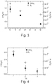
- Spraying is carried out at room temperature (20-25 ° C). The conductivity of the samples is monitored after each layer deposition during the deposition process to ensure that the resistance of the film evolves as expected as a function of the number of layers ( figure 3 ). After the spray deposition, the samples are dried at room temperature for 24 hours under vacuum.
- the average thickness of the sensors measured by AFM and SEM can be measured as a function of the number of layers sprayed.
- sLbL is a very versatile technique that makes it possible to deposit on any type of surface provided that it has a surface energy compatible with the constituents of the spray solution.
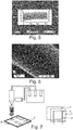
- this technique was implemented on a textile and at the figure 6 on a non-conductive fiber, namely a fiberglass.
- the sensitive film created by spray can thus be formed on a composite sail of a boat to follow the deformations, as explained in the article C. Robert, JF Feller, M. Castro, Sensing skin for strain monitoring made of PC-CNT conductive polymer nanocomposite sprayed layer by layer, ACS Applied Materials & Interfaces, 2012, 4, 7, 3508-3516 or at the interface of the reinforcing folds and the resin in the composites as explained in the article I. Pillin, M. Castro, S. Nag Chowdhury, JF Feller, Robustness of carbon nanotube sensing interphase to probe composites' interfacial damage in-situ, Journal of Composite Materials, doi: 10.1177 / 0021998315571029, (2015 ).
- the spraying is carried out through a mask whose dimensions can be adjusted according to the expected stresses and the substrate 1 considered, on at least two electrodes (cf. figure 7 ) which may be conductive wire or fiber made of carbon or metal (Cu, Ni, Ag, Au ...), the contact with the film CPC transducer 2 on the one hand and the cables of the acquisition apparatuses on the other hand on the other hand, can be improved by the use of a conductive glue 3 (eg epoxy base heavily loaded with silver particles).
- a conductive glue 3 eg epoxy base heavily loaded with silver particles.
- a protective layer 4 can be added.
- the substrate may be an interdigitated electrode or a PET film or transparent PLA and in this case it can be provided that the CPC deposit is also.
- the substrate may be a pre-cured resin film (prepreg) which after spraying of the electrically conductive layer of CPC will be associated on the surface or in a structural composite and baked with it.
- prepreg pre-cured resin film
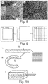
- the invention further relates to a sensor in which the multilayer structure is folded in two.
- the three-layer patch of the figure 10 allows locating the electrically conductive architecture 5 (the transducer) manufactured by sLbL sandwiched between two layers of electrical insulating polymer 6 and preventing any short circuit with the CF of the composite.
- This treatment has the effect if the polymer matrix is thermoplastic fluidify and promote interconnection of the nanoparticles dispersed there by dynamic percolation.
- This treatment makes it possible to increase the resistivity of the sensor to a "threshold" value where the resistivity remains constant. When this resistivity value is reached, the cooking step is stopped.
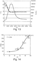
- thermosetting matrix sensors For thermosetting matrix sensors, the effect of cooking is to vary the degree of crosslinking which causes aggregation of the conductive nanoparticles and thus decreases the resistance of the conductive network, as can be seen in FIG. figure 13 .
- the temperature T and the resistances R1 and R2 of two different sensors are illustrated as a function of time t.
- the baking conditions of the EP resin make it possible to control the mechanical properties ( figure 14 ) and electrical CPC sensors.
- the invention further relates, independently or in combination with the foregoing, to a seal having a sensor as defined above.
- a seal consists of a deformable material intended to be clamped between connecting elements (eg flanges, tubes, etc.) to prevent leakage of the fluid contained in said connecting elements.
- Seals are present in all devices in which a fluid is circulated.
- a seal is subjected to a clamping force that must not exceed a maximum pressure causing unacceptable creep of the gasket material under tension, but sufficient to maintain the minimum pressure necessary for assembly of the seal. seal to achieve the desired level of sealing under the operating conditions.
- the senor according to the invention can be used to obtain the information required at a joint without modifying the operation of the device to be controlled.
- the senor according to the invention can be placed at various points on the joint, especially at the surface or at the core, so it can be judiciously placed according to the geometry of the joint where it collects the information is the most relevant .
- the senor provides continuous information including the mechanical state of the seal.
- a sensor on the outer face of the gasket, that is to say outside the assembly element, information concerning a possible leakage of the fluid can be obtained.
- the information obtained may be of a qualitative or quantitative nature.
- patches also makes it possible to distribute the sensors over the entire device to be controlled.
- a judicious distribution of the patches can make it possible to obtain both local information, at the level of each patch, and general information, by considering the information obtained by all the patches, making it possible to obtain information about the patches. state of the entire device to be controlled.
- the seal may be chosen from the following list, which is not limited to: elastomer seal, fiber-elastomer composite seal, graphite seal, PTFE seal, modified PTFE seal, metalloplastic seal, spiral seal , metalloplastic seal, grooved seal, O-ring.
- the addition or integration of a CPC sensor can provide information on the mechanical stress level of the seal, the compromise of its integrity by chemical agents or on a possible degradation may cause a leak.
- the seal may comprise at least one sensor or a precursor sensor configured to detect a leak of a chemical compound, the chemical compound being for example chosen from the following list, which is not limiting: H 2 O, H 2 , O 2 , CO 2 , CH 2 O, CHCl 3 , C 6 H 6 , CH 3 OH, CH 3 CH 2 OH, and other volatile or liquid organic compounds such as chlorinated solvents, alcohols, ketones, aldehydes. .
- the sensor may be configured such that detection is possible as soon as a very small amount of the order of a few parts per million (ppm) of the chemical compound is present.
- CPC sensors are easy to use because of their adaptability. They can be integrated into a joint in different ways, for example by melting or in solution. In the latter case, they can be structured in nanometric multilayers and integrated in or on various supports.
- Films based on nanotubes are used in particular to control devices such as surface or core joints.
- a sensor array according to the invention based on conductive polymer nanocomposites (CPC) loaded with CNT and / or GR graphene sheets dispersed in a polymer or elastomer matrix (for example: EP, TPU ), at the surface or in the joint to fulfill a dual function: (1) the monitoring of the clamping force of the joint below which the seal will no longer be ensured; (2) Detecting a leak may be due to the fluid diffusion under operating condition.
- CPC conductive polymer nanocomposites
- the sensor may be disposed at the surface of the seal.
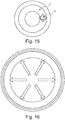
- We illustrated on the figure 15 the structure of a gasket 8 intended to be sandwiched between two flanges and the possible arrangement of the CPC sensor 10 on its surface.
- a flat gasket 12 carrying a sensor 14 having a circular shape It may be a single sensor or a set of sensors arranged in a circle.
- the senor may be placed on the surface or on the edge of the seal.
- CPC sensors are also particularly sensitive to a variation in temperature or organic vapor diffusing through a membrane polymer.
- CPC-based sensors can also be used to develop monitoring and safety systems to quickly alert you when a seal fails.
- the advantage of the proposed technology also comes from the ease of manufacturing CPCs, which allows large-scale development, low cost and does not require heavy industrial investment to adapt existing joint manufacturing processes.
- this type of formulation can be particularly suitable for monitoring the compression of a joint if the expected deformations are weak ⁇ 0.5%.
- TPU thermoplastic poly (urethane)
- seals comprising a CPC sensor according to the invention is presented in the section devoted to the examples. In particular, the sensitivity of CPCs to pressure, temperature and organic vapors was tested.
- the size of the core of the fibers is between 50 and 150 microns which makes them relatively intrusive elements when they are inserted in composites whose fibers have a diameter of 10 microns.
- optical fibers are sensitive to organic compounds such as moisture or some reagents of polymers, so they must be protected by a polymer sheath that makes them also more compatible with the polymer matrix of the composite. This operation further contributes to increasing the diameter of the optical fibers from 60 to 100 ⁇ m.
- optical fibers detect only the elongations in a field of elastic deformation, or it does not occur damage which is precisely what we seek to characterize.
- Ultrasonic sensors can detect fiber breakage or fiber matrix interface but not deformations, and can not easily locate the damage because not integrable to heart. Reinforcement materials can absorb ultrasound and make it difficult to interpret signals. In practice they serve only to know if the level of deformation not to be exceeded has been reached, but in general it is too late.
- the metal gauges are heterogeneous, they must be glued, are not integrable, and their sensitivity is low compared to the QRS whose gauge factor can be adapted according to the range of deformation of the material to follow.
- the accelerometers are of a large size, which does not allow their integration at heart, and requires a surface gluing of the materials which one wishes to follow the health. On the other hand, their positioning must be very precise in relation to each other.
- the sensor according to the invention has an effect of memorizing the damages and stress suffered by the material to be monitored.
- the sensors according to the invention meet this need.
- the senor according to the invention can also be used for monitoring the firing of composites or the control of the composite molds used to manufacture them, or to monitor the process of curing the composite structure in situ .
- FIG 17 a CF-EP composite cable for sailboat stay instrumented by CPC sensors.
- the sailboat guy used is made of composite carbon fiber / poly (epoxy).
- the figure 17 presents the arrangement of the CPC sensors on the CF-EP cable of a stay and the layout of the CPC sensors on the CF-EP cable and the details of the connections.
- EP-CNT sensors were previously tested in the laboratory in static mode. According to figure 17 , four CPC sensors were placed on samples of CF-EP cables of the same nature as those used for the guys but having two loops to be installed on a traction machine.
- TPU thermoplastic polyurethane films containing 33% by weight of hard segment (Dupont) of a thickness of about 1.5 mm were hot pressed and at 20 bar at 160 ° C to be used as substrates for TPU sensors containing 2% w / w CNT dispersion in THF solution under sonication for 1h.
- CPC sensors were manufactured by dispersing 2% CNT m / m in DGEBA and chloroform under sonication for 1h.
- the piezoresistive properties of two types of pressurized CPC sensors were measured using the uniaxial dynamic pressure test system consisting of a universal test machine (INSTRON 5566A) instrumented by two electrometers (Fluke 8842A and 8846A) controlled by a program developed under LabVIEW.
- the prepared CPC sensors were connected to a multimeter for resistance measurement.
- the compression stress imposed by the test machine was applied perpendicularly to the sensors giving differential relative resistance responses.
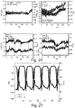
- the figure 21 illustrates the resistive response (resistance R) of a CPC TPU-3% CNT sensor and the load L applied as a function of time t.
- the figure 22 illustrates the piezoresistive response, namely the ⁇ R / R 0 resistance variation in% of the EP-2% CNT and TPU-3% CNT sensors as a function of the applied pressure P. It can be seen that overall TPU-3% CNT sensors are more sensitive than EP-2% CNT sensors.
- thermo-resistive response ⁇ R / R 0 of the EP-2% CNT and TPU-3% CNT sensors is presented at temperature increments as a function of time.
- the two sensors EP-2% CNT and TPU-3% CNT respond with the same dynamics, even if the sensitivity of the first is slightly higher, by cons when they are subject to a temperature ramp the sensitivity of the TPU-3% CNT sensor is greater.
- CPC TPU-3% CNT sensors were sprayed onto PLA films to check their sensitivity to VOC and show their ability to detect leaks of liquids or vapor in the joints.
- the chemo-resistive response of the TPU-3% CNT deposited on a THF-exposed PLA film is presented.
- the evolution of the sensitivity of the resistance ⁇ R / R 0 as a function of time has been illustrated for four sensors 1, 2, 3 and 4.
- the sensors 1 to 3 are electrode sensors, and the sensor 4 is a film sensor. .
- TPU matrix For applications at higher temperatures it is necessary to consider changing the TPU matrix by a stable polymer at higher temperature such as poly (ether-ether-ketone) PEEK, poly (siloxane) or poly (imide).
- a stable polymer at higher temperature such as poly (ether-ether-ketone) PEEK, poly (siloxane) or poly (imide).
Landscapes
- Chemical & Material Sciences (AREA)
- Physics & Mathematics (AREA)
- General Physics & Mathematics (AREA)
- Health & Medical Sciences (AREA)
- Chemical Kinetics & Catalysis (AREA)
- Medicinal Chemistry (AREA)
- Polymers & Plastics (AREA)
- Organic Chemistry (AREA)
- Spectroscopy & Molecular Physics (AREA)
- Dispersion Chemistry (AREA)
- Inorganic Chemistry (AREA)
- Engineering & Computer Science (AREA)
- Manufacturing & Machinery (AREA)
- Materials Engineering (AREA)
- Compositions Of Macromolecular Compounds (AREA)
- Investigating Or Analyzing Materials By The Use Of Fluid Adsorption Or Reactions (AREA)
- Investigating Or Analyzing Materials By The Use Of Electric Means (AREA)
- Force Measurement Appropriate To Specific Purposes (AREA)
- Measuring Temperature Or Quantity Of Heat (AREA)
Claims (15)
- Sensor für ein physisches Merkmal, umfassend eine Mehrschichtstruktur, umfassend:- mindestens eine elektrisch leitende Schicht, umfassend Nanofüllstoffe in einer Polymermatrix, umfassend mindestens ein Polymer,- und elektrische Anschlussmittel,wobei die Struktur wärmehärtend, thermoplastisch ist oder ein vernetzbares Elastomer ist,
dadurch gekennzeichnet, dass, wenn die Struktur wärmehärtend ist, ihr Vernetzungsgrad über 80 %, besser über 90 %, ja sogar über 95 % liegt,
wenn die Struktur ein vernetzbares Elastomer ist, sie dann einen Gehalt an Vernetzungsmittel im Bereich von 5 bis 20 Mol-%, bezogen auf die Anzahl der Mole der Struktur, aufweist und,
wenn die Struktur thermoplastisch ist, sie einen konstanten Wert des spezifischen Widerstands und vorzugsweise einen Kristallinitätsgrad von 0 % bis 60 % aufweist,
wobei der Sensor eine Anzahl an elektrisch leitenden Schichten von mindestens zwei Schichten aufweist. - Sensor nach dem vorhergehenden Anspruch, umfassend eine Anzahl an elektrisch leitenden Schichten von 2 bis 100 Schichten, ja sogar von 2 bis 90, besser von 3 bis 80, insbesondere von 20 bis 70, beispielsweise von 40 bis 50, aufweist.
- Sensor nach einem der vorhergehenden Ansprüche, umfassend eine Substratschicht, auf der die elektrisch leitenden Schichten aufgebracht sind, das Substrat ist vorteilhafterweise eine isolierende Schicht, die mindestens ein Polymer umfasst, wobei das Polymer zu dem Polymer der elektrisch leitenden Schicht identisch oder davon verschieden sein kann.
- Sensor nach einem der vorhergehenden Ansprüche, dadurch gekennzeichnet, dass er in Form eines Patches ist.
- Sensor nach einem der vorhergehenden Ansprüche, wobei die Mehrschichtstruktur in zwei Hälften gefaltet ist.
- Sensor nach einem der vorhergehenden Ansprüche, wobei die Nanofüllstoffe aus der folgenden Liste ausgewählt sind: Nanopartikel aus Kohlenstoff, Ruß, Nanoröhrchen aus Kohlenstoff, Graphen, Fulleren, Metall-Nanopartikel, Silber-Nanopartikel, Gold-Nanopartikel, Nickel-Nanopartikel.
- Sensor nach einem der vorhergehenden Ansprüche, wobei die elektrisch leitenden Schichten eine Dicke von 20 bis 100 nm, vorzugsweise von 30 bis 60, ja sogar von 40 bis 50 nm, aufweisen.
- Sensor nach einem der vorhergehenden Ansprüche, wobei die Polymermatrix ein Polymer umfasst, das aus der folgenden Liste ausgewählt ist: Elastomer, beispielsweise Polysiloxan, Polyurethan, Polyisopren, Polybutadien.
- Material, insbesondere Verbundmaterial, umfassend mindestens einen Sensor nach einem der Ansprüche 1 bis 8.
- Verbundmaterial nach dem vorhergehenden Anspruch, wobei mindestens ein Sensor direkt in die Faseroberfläche, beispielsweise Glasfasern oder Kohlenstoff, des Verbundmaterials eingefügt ist.
- Verbundmaterial nach einem der zwei vorhergehenden Ansprüche, umfassend mindestens einen Sensor, der in eine Matrix, beispielsweise eine Polymermatrix, des Verbundmaterials eingefügt ist.
- Verbundmaterial nach einem der drei vorhergehenden Ansprüche, wobei eine Polymermatrix des Verbundmaterials ein Polymer umfasst, das mit einem Polymer der Polymermatrix des Sensors oder des Sensorvorläufers kompatibel, ja sogar dazu identisch ist.
- Verwendung eines Sensors nach einem der Ansprüche 1 bis 8 in einem Kabel oder bei der Herstellung eines Kabels.
- Verwendung eines Sensors nach einem der Ansprüche 1 bis 8 in einem Rohr oder bei der Herstellung eines Rohrs.
- Verwendung eines Sensors nach einem der Ansprüche 1 bis 8 in einer Windkraftanlage, einer Turbine oder einer Gezeitenturbine oder bei der Herstellung einer Windkraftanlage, einer Turbine oder einer Gezeitenturbine oder in einer Dichtung, wobei die Dichtung insbesondere mindestens einen Sensor für ein physisches Merkmal aufweist, der eine Mehrschichtstruktur aufweisen kann, umfassend:- mindestens zwei, insbesondere mindestens drei elektrisch leitende Schichten, umfassend Nanofüllstoffe, die insbesondere beschichtet sein können, in einer Polymermatrix, umfassend mindestens ein Polymer, und- elektrische Anschlussmittel,wobei die mehrschichtige Struktur insbesondere einem kontrollierten Einbrennzyklus unterzogen worden ist,
wobei die Dichtung insbesondere mindestens einen Sensor oder Sensorvorläufer aufweisen kann, der auf der Oberfläche der Dichtung eingefügt ist.
Priority Applications (1)
| Application Number | Priority Date | Filing Date | Title |
|---|---|---|---|
| PL16741573T PL3320306T3 (pl) | 2015-07-10 | 2016-07-08 | Czujnik właściwości fizycznej, zawierający korzystnie strukturę wielowarstwową |
Applications Claiming Priority (2)
| Application Number | Priority Date | Filing Date | Title |
|---|---|---|---|
| FR1556583A FR3038710B1 (fr) | 2015-07-10 | 2015-07-10 | Capteur d'une caracteristique physique, comportant de preference une structure multicouches |
| PCT/EP2016/066348 WO2017009256A1 (fr) | 2015-07-10 | 2016-07-08 | Capteur d'une caracteristique physique, comportant de preference une structure multicouches |
Publications (2)
| Publication Number | Publication Date |
|---|---|
| EP3320306A1 EP3320306A1 (de) | 2018-05-16 |
| EP3320306B1 true EP3320306B1 (de) | 2019-09-11 |
Family
ID=54066117
Family Applications (1)
| Application Number | Title | Priority Date | Filing Date |
|---|---|---|---|
| EP16741573.6A Active EP3320306B1 (de) | 2015-07-10 | 2016-07-08 | Sensor für ein physisches merkmal, vorzugsweise mit einer mehrschichtstruktur |
Country Status (8)
| Country | Link |
|---|---|
| US (1) | US10890498B2 (de) |
| EP (1) | EP3320306B1 (de) |
| CN (1) | CN108351233B (de) |
| DK (1) | DK3320306T3 (de) |
| ES (1) | ES2761823T3 (de) |
| FR (1) | FR3038710B1 (de) |
| PL (1) | PL3320306T3 (de) |
| WO (1) | WO2017009256A1 (de) |
Families Citing this family (18)
| Publication number | Priority date | Publication date | Assignee | Title |
|---|---|---|---|---|
| CN109374159B (zh) * | 2018-09-28 | 2020-09-08 | 深圳大学 | 一种多壁碳纳米管压阻传感器及其制备方法 |
| CN109881297B (zh) * | 2019-03-01 | 2022-06-28 | 苏州城邦达益材料科技有限公司 | 一种电学性能可变的组合物、纳米纤维及其制备方法 |
| CN110333011B (zh) * | 2019-07-08 | 2021-12-10 | 杭州高烯科技有限公司 | 一种压力传感器 |
| TWI759815B (zh) * | 2019-08-15 | 2022-04-01 | 國立清華大學 | 彈性導電柱體、製造方法及使用其的探針卡 |
| GB2588683A (en) * | 2019-11-04 | 2021-05-05 | Nokia Technologies Oy | Electromechanical sensors |
| WO2021113908A1 (en) * | 2019-12-09 | 2021-06-17 | Swinburne University Of Technology | Piezoresponsive fibre reinforced polymer composite |
| FR3104714B1 (fr) * | 2019-12-11 | 2021-11-26 | Saint Gobain Ct Recherches | Dispositif de controle d’une piece fragile |
| FR3104711B1 (fr) | 2019-12-11 | 2021-11-26 | Saint Gobain Ct Recherches | Dispositif de controle d'un blindage |
| FR3104713B1 (fr) | 2019-12-11 | 2026-02-13 | Saint Gobain Ct Recherches | Capteur ceramique |
| CN111060234B (zh) * | 2019-12-30 | 2023-11-28 | 浙江清华柔性电子技术研究院 | 功能浆料及其应用 |
| US11045111B1 (en) * | 2020-05-18 | 2021-06-29 | Canary Health Technologies Inc. | Real time breath analyzer for detecting volatile organic compounds and identifying diseases or disorders |
| FR3123975B1 (fr) | 2021-06-09 | 2026-03-20 | Saint Gobain Ct Recherches | Plaque instrumentee pour four |
| CN115597645B (zh) * | 2021-07-07 | 2025-08-29 | 腾讯科技(深圳)有限公司 | 传感器及其功能层粘接方法 |
| CN113720503B (zh) * | 2021-08-18 | 2024-03-26 | 中国科学院重庆绿色智能技术研究院 | 一种大面阵高灵敏柔弹性压力传感器及其制备方法 |
| CN115560886B (zh) * | 2022-09-19 | 2025-04-08 | 西安电子科技大学 | 基于压电势增强摩擦电效应的无源压力传感器及制备方法 |
| CN115648779B (zh) * | 2022-10-26 | 2025-09-26 | 北京航空航天大学 | 一种基于tpu的柔性电子皮肤及其制备方法 |
| FR3149689A1 (fr) | 2023-06-08 | 2024-12-13 | L'air Liquide, Société Anonyme pour l'Étude et l'Exploitation des Procédés Georges Claude | Pièce de structure incorporant un capteur et procédé pour sa surveillance. |
| CN120059268B (zh) * | 2025-04-25 | 2025-08-08 | 黄山久石科技发展有限公司 | 一种吸能预警复合材料及其制备方法和应用 |
Family Cites Families (25)
| Publication number | Priority date | Publication date | Assignee | Title |
|---|---|---|---|---|
| SE468026B (sv) * | 1990-06-05 | 1992-10-19 | Asea Brown Boveri | Saett att framstaella en elektrisk anordning |
| US6835311B2 (en) * | 2002-01-31 | 2004-12-28 | Koslow Technologies Corporation | Microporous filter media, filtration systems containing same, and methods of making and using |
| US7730547B2 (en) | 2003-01-23 | 2010-06-01 | William Marsh Rice University | Smart materials: strain sensing and stress determination by means of nanotube sensing systems, composites, and devices |
| EP1725859A4 (de) * | 2004-02-24 | 2007-10-17 | Polymer Aging Concepts Inc | Zustandsüberwachungsverfahren und -vorrichtung für verbundwerkstoffe |
| EP1838522A4 (de) * | 2004-12-30 | 2011-03-09 | Sun Drilling Products Corp | Duromere nanocompositteilchen, verfahren zu ihrer herstellung und ihre verwendung bei der förderung von erdöl und erdgas |
| CN100347127C (zh) * | 2005-10-28 | 2007-11-07 | 清华大学 | 一种兼备电容电感性能的复合材料及其制备方法 |
| CN101480858B (zh) | 2008-01-11 | 2014-12-10 | 清华大学 | 碳纳米管复合材料及其制备方法 |
| KR101074027B1 (ko) * | 2009-03-03 | 2011-10-17 | 한국과학기술연구원 | 그래펜 복합 나노섬유 및 그 제조 방법 |
| CN201594308U (zh) * | 2010-02-09 | 2010-09-29 | 李振强 | 一体化复合材料异物侵入传感器 |
| CN101798462B (zh) * | 2010-03-26 | 2011-11-16 | 武汉工程大学 | 石墨烯/导电高分子复合膜及其制备方法 |
| CN102374910B (zh) | 2010-08-23 | 2013-07-03 | 清华大学 | 碳纳米管/聚合物复合膜阵列式柔性力敏传感器及制法 |
| TWI446373B (zh) | 2010-10-14 | 2014-07-21 | Ind Tech Res Inst | 壓阻材料的製造方法、壓阻組成物與壓力感測裝置 |
| WO2012134452A1 (en) * | 2011-03-29 | 2012-10-04 | Empire Technology Development Llc | Two-particle nanocomposite dielectrics |
| GB201116472D0 (en) | 2011-09-23 | 2011-11-09 | Hexcel Composites Ltd | Conductive composite structure or laminate |
| JP5924725B2 (ja) | 2011-11-14 | 2016-05-25 | ヤマハ株式会社 | 歪みセンサ及び歪みセンサの製造方法 |
| KR102001403B1 (ko) * | 2012-02-09 | 2019-07-18 | 다우 코닝 도레이 캄파니 리미티드 | 구배 중합체 구조물 및 방법 |
| FR2991330B1 (fr) | 2012-06-04 | 2015-04-03 | Arkema France | Materiau composite a tres faible taux de nanocharges carbonees, son procede de preparation et ses utilisations |
| CN102692288B (zh) | 2012-06-15 | 2014-03-19 | 青岛大学 | 一种柔性力敏传感器的制备方法 |
| WO2014058806A1 (en) * | 2012-10-08 | 2014-04-17 | Stc.Unm | Improved pliable pressure-sensing fabric |
| EP2936581B1 (de) * | 2012-12-21 | 2018-11-21 | Dow Silicones Corporation | Mehrschichtige polymerstrukturen und verfahren |
| EP2801549B1 (de) | 2013-05-10 | 2018-01-31 | Yamaha Corporation | Dehnungssensor basierend auf Kohlenstoff-Nanoröhren und Verfahren zu dessen Herstellung |
| CN104622464A (zh) * | 2013-11-11 | 2015-05-20 | 克利夫兰医药聚合物有限公司 | 多功能纳米复合传感器和传感系统以及用于监测患者心血管系统的方法和聚合物组合物 |
| US9708451B2 (en) * | 2014-02-25 | 2017-07-18 | Lawrence Livermore National Security, Llc | Silicone elastomers capable of large isotropic dimensional change |
| US10399322B2 (en) * | 2014-06-11 | 2019-09-03 | Applied Nanostructured Solutions, Llc | Three-dimensional printing using carbon nanostructures |
| CN104257367B (zh) * | 2014-09-16 | 2016-04-06 | 苏州能斯达电子科技有限公司 | 一种可贴附柔性压力传感器及其制备方法 |
-
2015
- 2015-07-10 FR FR1556583A patent/FR3038710B1/fr active Active
-
2016
- 2016-07-08 DK DK16741573T patent/DK3320306T3/da active
- 2016-07-08 ES ES16741573T patent/ES2761823T3/es active Active
- 2016-07-08 US US15/740,407 patent/US10890498B2/en active Active
- 2016-07-08 CN CN201680040904.4A patent/CN108351233B/zh active Active
- 2016-07-08 WO PCT/EP2016/066348 patent/WO2017009256A1/fr not_active Ceased
- 2016-07-08 EP EP16741573.6A patent/EP3320306B1/de active Active
- 2016-07-08 PL PL16741573T patent/PL3320306T3/pl unknown
Non-Patent Citations (1)
| Title |
|---|
| None * |
Also Published As
| Publication number | Publication date |
|---|---|
| US20180195914A1 (en) | 2018-07-12 |
| FR3038710A1 (fr) | 2017-01-13 |
| FR3038710B1 (fr) | 2021-05-28 |
| CN108351233A (zh) | 2018-07-31 |
| CN108351233B (zh) | 2023-07-07 |
| US10890498B2 (en) | 2021-01-12 |
| WO2017009256A1 (fr) | 2017-01-19 |
| ES2761823T3 (es) | 2020-05-21 |
| PL3320306T3 (pl) | 2020-04-30 |
| EP3320306A1 (de) | 2018-05-16 |
| DK3320306T3 (da) | 2019-12-09 |
Similar Documents
| Publication | Publication Date | Title |
|---|---|---|
| EP3320306B1 (de) | Sensor für ein physisches merkmal, vorzugsweise mit einer mehrschichtstruktur | |
| Lu et al. | Real time monitoring of the curing degree and the manufacturing process of fiber reinforced composites with a carbon nanotube buckypaper sensor | |
| Nag-Chowdhury et al. | Non-intrusive health monitoring of infused composites with embedded carbon quantum piezo-resistive sensors | |
| Groo et al. | Laser induced graphene in fiberglass-reinforced composites for strain and damage sensing | |
| Tripathi et al. | Flax fibers–epoxy with embedded nanocomposite sensors to design lightweight smart bio-composites | |
| JP2011525240A (ja) | 複合構造体用の柔軟な無線の健全性監視センサー | |
| Wang et al. | An embedded non-intrusive graphene/epoxy broadband nanocomposite sensor co-cured with GFRP for in situ structural health monitoring | |
| Lachman et al. | Raman response of carbon nanotube/PVA fibers under strain | |
| Mei et al. | 3D‐Printed thermoplastic polyurethane/graphene composite with porous segregated structure: Toward ultralow percolation threshold and great strain sensitivity | |
| Mortensen et al. | Rapid assembly of multifunctional thin film sensors for wind turbine blade monitoring | |
| Li et al. | Organic vapor sensing behaviors of carbon black/poly (lactic acid) conductive biopolymer composite | |
| Fang et al. | A flexible and hydrophobic polyurethane elastomer used as binder for the activated carbon electrode in capacitive deionization | |
| Shahbaz et al. | Fabrication and analysis of integrated multifunctional MWCNTS sensors in glass fiber reinforced polymer composites | |
| Li et al. | Tuning the structure and performance of bulk and porous vapor sensors based on co-continuous carbon nanotube-filled blends of poly (vinylidene fluoride) and polycarbonates by varying melt viscosity | |
| Qiang et al. | An insulating second filler tuning porous conductive composites for highly sensitive and fast responsive organic vapor sensor | |
| Sam-Daliri et al. | Carbon nanotubes–Elium nanocomposite sensor for structural health monitoring of unidirectional glass fibre reinforced epoxy composite | |
| Sousa et al. | Multicomponent polyurethane–carbon black composite as piezoresistive sensor | |
| FR2996359A1 (fr) | Electrode transparente conductrice et procede de fabrication associe | |
| CA3205480A1 (en) | A process for obtaining dye from carbon nanomaterials, products and use in monitoring strains, stresses, and impact | |
| Keller et al. | Printed and laser-scribed stretchable conductors on thin elastomers for soft and wearable electronics | |
| de Freitas et al. | Thermoplastic starch and graphite biocomposite electrode for electrochemical catechol sensor | |
| Liu et al. | Flexible wearable biosensors from poly (ionic liquid) for real-time signal monitoring | |
| Kumar et al. | Efficacy of carbon nanotube bucky paper for interlaminar damage sensing in composites and fiber‐metal laminates | |
| Liu et al. | Self-Sensing Stress-Absorption Layer with Carbon Nanotubes Grafted onto Basalt Fibers | |
| Nisha et al. | Design and manufacture of nanofibers using electrospinning technique for aerospace application |
Legal Events
| Date | Code | Title | Description |
|---|---|---|---|
| STAA | Information on the status of an ep patent application or granted ep patent |
Free format text: STATUS: THE INTERNATIONAL PUBLICATION HAS BEEN MADE |
|
| PUAI | Public reference made under article 153(3) epc to a published international application that has entered the european phase |
Free format text: ORIGINAL CODE: 0009012 |
|
| STAA | Information on the status of an ep patent application or granted ep patent |
Free format text: STATUS: REQUEST FOR EXAMINATION WAS MADE |
|
| 17P | Request for examination filed |
Effective date: 20180212 |
|
| AK | Designated contracting states |
Kind code of ref document: A1 Designated state(s): AL AT BE BG CH CY CZ DE DK EE ES FI FR GB GR HR HU IE IS IT LI LT LU LV MC MK MT NL NO PL PT RO RS SE SI SK SM TR |
|
| AX | Request for extension of the european patent |
Extension state: BA ME |
|
| RIN1 | Information on inventor provided before grant (corrected) |
Inventor name: BENECH, GABRIEL Inventor name: TUNG, TRAN THAN Inventor name: LEGRAND, JEAN-MARC Inventor name: FELLER, JEAN-FRANCOIS Inventor name: CASTRO, MICKAEL |
|
| DAV | Request for validation of the european patent (deleted) | ||
| DAX | Request for extension of the european patent (deleted) | ||
| GRAP | Despatch of communication of intention to grant a patent |
Free format text: ORIGINAL CODE: EPIDOSNIGR1 |
|
| STAA | Information on the status of an ep patent application or granted ep patent |
Free format text: STATUS: GRANT OF PATENT IS INTENDED |
|
| RIC1 | Information provided on ipc code assigned before grant |
Ipc: C08K 5/00 20060101ALI20190111BHEP Ipc: C08L 83/04 20060101ALI20190111BHEP Ipc: B82Y 30/00 20110101ALI20190111BHEP Ipc: C08L 75/04 20060101ALI20190111BHEP Ipc: C08L 47/00 20060101ALI20190111BHEP Ipc: G01L 1/18 20060101ALI20190111BHEP Ipc: H01B 1/22 20060101ALI20190111BHEP Ipc: C08J 5/04 20060101ALI20190111BHEP Ipc: G01L 1/22 20060101ALI20190111BHEP Ipc: H01B 1/24 20060101ALI20190111BHEP Ipc: B82Y 15/00 20110101ALI20190111BHEP Ipc: G01D 21/00 20060101AFI20190111BHEP |
|
| INTG | Intention to grant announced |
Effective date: 20190204 |
|
| GRAS | Grant fee paid |
Free format text: ORIGINAL CODE: EPIDOSNIGR3 |
|
| GRAA | (expected) grant |
Free format text: ORIGINAL CODE: 0009210 |
|
| STAA | Information on the status of an ep patent application or granted ep patent |
Free format text: STATUS: THE PATENT HAS BEEN GRANTED |
|
| AK | Designated contracting states |
Kind code of ref document: B1 Designated state(s): AL AT BE BG CH CY CZ DE DK EE ES FI FR GB GR HR HU IE IS IT LI LT LU LV MC MK MT NL NO PL PT RO RS SE SI SK SM TR |
|
| REG | Reference to a national code |
Ref country code: GB Ref legal event code: FG4D Free format text: NOT ENGLISH |
|
| REG | Reference to a national code |
Ref country code: CH Ref legal event code: EP |
|
| REG | Reference to a national code |
Ref country code: AT Ref legal event code: REF Ref document number: 1179031 Country of ref document: AT Kind code of ref document: T Effective date: 20190915 |
|
| REG | Reference to a national code |
Ref country code: DE Ref legal event code: R096 Ref document number: 602016020432 Country of ref document: DE Ref country code: IE Ref legal event code: FG4D Free format text: LANGUAGE OF EP DOCUMENT: FRENCH |
|
| REG | Reference to a national code |
Ref country code: DK Ref legal event code: T3 Effective date: 20191203 |
|
| REG | Reference to a national code |
Ref country code: SE Ref legal event code: TRGR |
|
| REG | Reference to a national code |
Ref country code: NL Ref legal event code: FP |
|
| REG | Reference to a national code |
Ref country code: LT Ref legal event code: MG4D |
|
| PG25 | Lapsed in a contracting state [announced via postgrant information from national office to epo] |
Ref country code: FI Free format text: LAPSE BECAUSE OF FAILURE TO SUBMIT A TRANSLATION OF THE DESCRIPTION OR TO PAY THE FEE WITHIN THE PRESCRIBED TIME-LIMIT Effective date: 20190911 Ref country code: HR Free format text: LAPSE BECAUSE OF FAILURE TO SUBMIT A TRANSLATION OF THE DESCRIPTION OR TO PAY THE FEE WITHIN THE PRESCRIBED TIME-LIMIT Effective date: 20190911 Ref country code: BG Free format text: LAPSE BECAUSE OF FAILURE TO SUBMIT A TRANSLATION OF THE DESCRIPTION OR TO PAY THE FEE WITHIN THE PRESCRIBED TIME-LIMIT Effective date: 20191211 Ref country code: LT Free format text: LAPSE BECAUSE OF FAILURE TO SUBMIT A TRANSLATION OF THE DESCRIPTION OR TO PAY THE FEE WITHIN THE PRESCRIBED TIME-LIMIT Effective date: 20190911 Ref country code: NO Free format text: LAPSE BECAUSE OF FAILURE TO SUBMIT A TRANSLATION OF THE DESCRIPTION OR TO PAY THE FEE WITHIN THE PRESCRIBED TIME-LIMIT Effective date: 20191211 |
|
| PG25 | Lapsed in a contracting state [announced via postgrant information from national office to epo] |
Ref country code: LV Free format text: LAPSE BECAUSE OF FAILURE TO SUBMIT A TRANSLATION OF THE DESCRIPTION OR TO PAY THE FEE WITHIN THE PRESCRIBED TIME-LIMIT Effective date: 20190911 Ref country code: AL Free format text: LAPSE BECAUSE OF FAILURE TO SUBMIT A TRANSLATION OF THE DESCRIPTION OR TO PAY THE FEE WITHIN THE PRESCRIBED TIME-LIMIT Effective date: 20190911 Ref country code: RS Free format text: LAPSE BECAUSE OF FAILURE TO SUBMIT A TRANSLATION OF THE DESCRIPTION OR TO PAY THE FEE WITHIN THE PRESCRIBED TIME-LIMIT Effective date: 20190911 |
|
| REG | Reference to a national code |
Ref country code: GR Ref legal event code: EP Ref document number: 20190403656 Country of ref document: GR Effective date: 20200318 |
|
| PG25 | Lapsed in a contracting state [announced via postgrant information from national office to epo] |
Ref country code: EE Free format text: LAPSE BECAUSE OF FAILURE TO SUBMIT A TRANSLATION OF THE DESCRIPTION OR TO PAY THE FEE WITHIN THE PRESCRIBED TIME-LIMIT Effective date: 20190911 Ref country code: PT Free format text: LAPSE BECAUSE OF FAILURE TO SUBMIT A TRANSLATION OF THE DESCRIPTION OR TO PAY THE FEE WITHIN THE PRESCRIBED TIME-LIMIT Effective date: 20200113 Ref country code: RO Free format text: LAPSE BECAUSE OF FAILURE TO SUBMIT A TRANSLATION OF THE DESCRIPTION OR TO PAY THE FEE WITHIN THE PRESCRIBED TIME-LIMIT Effective date: 20190911 |
|
| REG | Reference to a national code |
Ref country code: ES Ref legal event code: FG2A Ref document number: 2761823 Country of ref document: ES Kind code of ref document: T3 Effective date: 20200521 |
|
| PG25 | Lapsed in a contracting state [announced via postgrant information from national office to epo] |
Ref country code: CZ Free format text: LAPSE BECAUSE OF FAILURE TO SUBMIT A TRANSLATION OF THE DESCRIPTION OR TO PAY THE FEE WITHIN THE PRESCRIBED TIME-LIMIT Effective date: 20190911 Ref country code: IS Free format text: LAPSE BECAUSE OF FAILURE TO SUBMIT A TRANSLATION OF THE DESCRIPTION OR TO PAY THE FEE WITHIN THE PRESCRIBED TIME-LIMIT Effective date: 20200224 Ref country code: SK Free format text: LAPSE BECAUSE OF FAILURE TO SUBMIT A TRANSLATION OF THE DESCRIPTION OR TO PAY THE FEE WITHIN THE PRESCRIBED TIME-LIMIT Effective date: 20190911 Ref country code: SM Free format text: LAPSE BECAUSE OF FAILURE TO SUBMIT A TRANSLATION OF THE DESCRIPTION OR TO PAY THE FEE WITHIN THE PRESCRIBED TIME-LIMIT Effective date: 20190911 |
|
| REG | Reference to a national code |
Ref country code: DE Ref legal event code: R097 Ref document number: 602016020432 Country of ref document: DE |
|
| PLBE | No opposition filed within time limit |
Free format text: ORIGINAL CODE: 0009261 |
|
| STAA | Information on the status of an ep patent application or granted ep patent |
Free format text: STATUS: NO OPPOSITION FILED WITHIN TIME LIMIT |
|
| PG2D | Information on lapse in contracting state deleted |
Ref country code: IS |
|
| PG25 | Lapsed in a contracting state [announced via postgrant information from national office to epo] |
Ref country code: IS Free format text: LAPSE BECAUSE OF FAILURE TO SUBMIT A TRANSLATION OF THE DESCRIPTION OR TO PAY THE FEE WITHIN THE PRESCRIBED TIME-LIMIT Effective date: 20200112 |
|
| 26N | No opposition filed |
Effective date: 20200615 |
|
| PG25 | Lapsed in a contracting state [announced via postgrant information from national office to epo] |
Ref country code: SI Free format text: LAPSE BECAUSE OF FAILURE TO SUBMIT A TRANSLATION OF THE DESCRIPTION OR TO PAY THE FEE WITHIN THE PRESCRIBED TIME-LIMIT Effective date: 20190911 |
|
| PG25 | Lapsed in a contracting state [announced via postgrant information from national office to epo] |
Ref country code: MC Free format text: LAPSE BECAUSE OF FAILURE TO SUBMIT A TRANSLATION OF THE DESCRIPTION OR TO PAY THE FEE WITHIN THE PRESCRIBED TIME-LIMIT Effective date: 20190911 |
|
| REG | Reference to a national code |
Ref country code: CH Ref legal event code: PL |
|
| PG25 | Lapsed in a contracting state [announced via postgrant information from national office to epo] |
Ref country code: CH Free format text: LAPSE BECAUSE OF NON-PAYMENT OF DUE FEES Effective date: 20200731 Ref country code: LU Free format text: LAPSE BECAUSE OF NON-PAYMENT OF DUE FEES Effective date: 20200708 Ref country code: LI Free format text: LAPSE BECAUSE OF NON-PAYMENT OF DUE FEES Effective date: 20200731 |
|
| PG25 | Lapsed in a contracting state [announced via postgrant information from national office to epo] |
Ref country code: TR Free format text: LAPSE BECAUSE OF FAILURE TO SUBMIT A TRANSLATION OF THE DESCRIPTION OR TO PAY THE FEE WITHIN THE PRESCRIBED TIME-LIMIT Effective date: 20190911 Ref country code: MT Free format text: LAPSE BECAUSE OF FAILURE TO SUBMIT A TRANSLATION OF THE DESCRIPTION OR TO PAY THE FEE WITHIN THE PRESCRIBED TIME-LIMIT Effective date: 20190911 Ref country code: CY Free format text: LAPSE BECAUSE OF FAILURE TO SUBMIT A TRANSLATION OF THE DESCRIPTION OR TO PAY THE FEE WITHIN THE PRESCRIBED TIME-LIMIT Effective date: 20190911 |
|
| PG25 | Lapsed in a contracting state [announced via postgrant information from national office to epo] |
Ref country code: MK Free format text: LAPSE BECAUSE OF FAILURE TO SUBMIT A TRANSLATION OF THE DESCRIPTION OR TO PAY THE FEE WITHIN THE PRESCRIBED TIME-LIMIT Effective date: 20190911 |
|
| P01 | Opt-out of the competence of the unified patent court (upc) registered |
Effective date: 20230527 |
|
| PGFP | Annual fee paid to national office [announced via postgrant information from national office to epo] |
Ref country code: IE Payment date: 20240618 Year of fee payment: 9 |
|
| PGFP | Annual fee paid to national office [announced via postgrant information from national office to epo] |
Ref country code: DK Payment date: 20240628 Year of fee payment: 9 |
|
| PGFP | Annual fee paid to national office [announced via postgrant information from national office to epo] |
Ref country code: GR Payment date: 20240625 Year of fee payment: 9 |
|
| PGFP | Annual fee paid to national office [announced via postgrant information from national office to epo] |
Ref country code: PL Payment date: 20240619 Year of fee payment: 9 |
|
| PGFP | Annual fee paid to national office [announced via postgrant information from national office to epo] |
Ref country code: BE Payment date: 20240726 Year of fee payment: 9 |
|
| PGFP | Annual fee paid to national office [announced via postgrant information from national office to epo] |
Ref country code: ES Payment date: 20240809 Year of fee payment: 9 |
|
| PGFP | Annual fee paid to national office [announced via postgrant information from national office to epo] |
Ref country code: AT Payment date: 20240621 Year of fee payment: 9 |
|
| PGFP | Annual fee paid to national office [announced via postgrant information from national office to epo] |
Ref country code: SE Payment date: 20240726 Year of fee payment: 9 |
|
| PGFP | Annual fee paid to national office [announced via postgrant information from national office to epo] |
Ref country code: NL Payment date: 20250630 Year of fee payment: 10 |
|
| PGFP | Annual fee paid to national office [announced via postgrant information from national office to epo] |
Ref country code: DE Payment date: 20250711 Year of fee payment: 10 |
|
| PGFP | Annual fee paid to national office [announced via postgrant information from national office to epo] |
Ref country code: IT Payment date: 20250708 Year of fee payment: 10 |
|
| PGFP | Annual fee paid to national office [announced via postgrant information from national office to epo] |
Ref country code: GB Payment date: 20250723 Year of fee payment: 10 |
|
| PGFP | Annual fee paid to national office [announced via postgrant information from national office to epo] |
Ref country code: FR Payment date: 20250730 Year of fee payment: 10 |
|
| REG | Reference to a national code |
Ref country code: DK Ref legal event code: EBP Effective date: 20250731 |
|
| REG | Reference to a national code |
Ref country code: AT Ref legal event code: MM01 Ref document number: 1179031 Country of ref document: AT Kind code of ref document: T Effective date: 20250708 |
|
| REG | Reference to a national code |
Ref country code: BE Ref legal event code: MM Effective date: 20250731 |
|
| PG25 | Lapsed in a contracting state [announced via postgrant information from national office to epo] |
Ref country code: AT Free format text: LAPSE BECAUSE OF NON-PAYMENT OF DUE FEES Effective date: 20250708 |
|
| PG25 | Lapsed in a contracting state [announced via postgrant information from national office to epo] |
Ref country code: BE Free format text: LAPSE BECAUSE OF NON-PAYMENT OF DUE FEES Effective date: 20250731 |
|
| PG25 | Lapsed in a contracting state [announced via postgrant information from national office to epo] |
Ref country code: GR Free format text: LAPSE BECAUSE OF NON-PAYMENT OF DUE FEES Effective date: 20260204 |