EP3320219B1 - Screw instrumented with extensometric strain gauges to measure the tensile and/or shear strain experienced by the screw - Google Patents
Screw instrumented with extensometric strain gauges to measure the tensile and/or shear strain experienced by the screw Download PDFInfo
- Publication number
- EP3320219B1 EP3320219B1 EP16757275.9A EP16757275A EP3320219B1 EP 3320219 B1 EP3320219 B1 EP 3320219B1 EP 16757275 A EP16757275 A EP 16757275A EP 3320219 B1 EP3320219 B1 EP 3320219B1
- Authority
- EP
- European Patent Office
- Prior art keywords
- gauges
- screw
- conical hole
- screw head
- head
- Prior art date
- Legal status (The legal status is an assumption and is not a legal conclusion. Google has not performed a legal analysis and makes no representation as to the accuracy of the status listed.)
- Active
Links
- 238000005259 measurement Methods 0.000 claims description 35
- 238000010008 shearing Methods 0.000 claims description 10
- 238000004891 communication Methods 0.000 claims description 6
- 230000007423 decrease Effects 0.000 description 11
- 230000000694 effects Effects 0.000 description 11
- 238000010586 diagram Methods 0.000 description 8
- 238000000034 method Methods 0.000 description 7
- 230000003071 parasitic effect Effects 0.000 description 4
- 230000005540 biological transmission Effects 0.000 description 3
- 238000004026 adhesive bonding Methods 0.000 description 2
- 238000011088 calibration curve Methods 0.000 description 2
- 238000006073 displacement reaction Methods 0.000 description 2
- 230000006870 function Effects 0.000 description 2
- 230000035945 sensitivity Effects 0.000 description 2
- 238000012546 transfer Methods 0.000 description 2
- 241001080024 Telles Species 0.000 description 1
- 230000003321 amplification Effects 0.000 description 1
- 230000000712 assembly Effects 0.000 description 1
- 238000000429 assembly Methods 0.000 description 1
- TZCXTZWJZNENPQ-UHFFFAOYSA-L barium sulfate Chemical compound [Ba+2].[O-]S([O-])(=O)=O TZCXTZWJZNENPQ-UHFFFAOYSA-L 0.000 description 1
- 230000008602 contraction Effects 0.000 description 1
- 230000006866 deterioration Effects 0.000 description 1
- 229940082150 encore Drugs 0.000 description 1
- 238000009434 installation Methods 0.000 description 1
- 238000012423 maintenance Methods 0.000 description 1
- 238000012986 modification Methods 0.000 description 1
- 230000004048 modification Effects 0.000 description 1
- 238000003199 nucleic acid amplification method Methods 0.000 description 1
- 244000045947 parasite Species 0.000 description 1
- 238000012545 processing Methods 0.000 description 1
- 230000000284 resting effect Effects 0.000 description 1
- 238000000926 separation method Methods 0.000 description 1
- 238000004904 shortening Methods 0.000 description 1
Images

Classifications
-
- F—MECHANICAL ENGINEERING; LIGHTING; HEATING; WEAPONS; BLASTING
- F16—ENGINEERING ELEMENTS AND UNITS; GENERAL MEASURES FOR PRODUCING AND MAINTAINING EFFECTIVE FUNCTIONING OF MACHINES OR INSTALLATIONS; THERMAL INSULATION IN GENERAL
- F16B—DEVICES FOR FASTENING OR SECURING CONSTRUCTIONAL ELEMENTS OR MACHINE PARTS TOGETHER, e.g. NAILS, BOLTS, CIRCLIPS, CLAMPS, CLIPS OR WEDGES; JOINTS OR JOINTING
- F16B31/00—Screwed connections specially modified in view of tensile load; Break-bolts
- F16B31/02—Screwed connections specially modified in view of tensile load; Break-bolts for indicating the attainment of a particular tensile load or limiting tensile load
-
- G—PHYSICS
- G01—MEASURING; TESTING
- G01L—MEASURING FORCE, STRESS, TORQUE, WORK, MECHANICAL POWER, MECHANICAL EFFICIENCY, OR FLUID PRESSURE
- G01L1/00—Measuring force or stress, in general
- G01L1/20—Measuring force or stress, in general by measuring variations in ohmic resistance of solid materials or of electrically-conductive fluids; by making use of electrokinetic cells, i.e. liquid-containing cells wherein an electrical potential is produced or varied upon the application of stress
- G01L1/22—Measuring force or stress, in general by measuring variations in ohmic resistance of solid materials or of electrically-conductive fluids; by making use of electrokinetic cells, i.e. liquid-containing cells wherein an electrical potential is produced or varied upon the application of stress using resistance strain gauges
-
- G—PHYSICS
- G01—MEASURING; TESTING
- G01L—MEASURING FORCE, STRESS, TORQUE, WORK, MECHANICAL POWER, MECHANICAL EFFICIENCY, OR FLUID PRESSURE
- G01L5/00—Apparatus for, or methods of, measuring force, work, mechanical power, or torque, specially adapted for specific purposes
- G01L5/24—Apparatus for, or methods of, measuring force, work, mechanical power, or torque, specially adapted for specific purposes for determining value of torque or twisting moment for tightening a nut or other member which is similarly stressed
-
- F—MECHANICAL ENGINEERING; LIGHTING; HEATING; WEAPONS; BLASTING
- F16—ENGINEERING ELEMENTS AND UNITS; GENERAL MEASURES FOR PRODUCING AND MAINTAINING EFFECTIVE FUNCTIONING OF MACHINES OR INSTALLATIONS; THERMAL INSULATION IN GENERAL
- F16B—DEVICES FOR FASTENING OR SECURING CONSTRUCTIONAL ELEMENTS OR MACHINE PARTS TOGETHER, e.g. NAILS, BOLTS, CIRCLIPS, CLAMPS, CLIPS OR WEDGES; JOINTS OR JOINTING
- F16B31/00—Screwed connections specially modified in view of tensile load; Break-bolts
- F16B31/02—Screwed connections specially modified in view of tensile load; Break-bolts for indicating the attainment of a particular tensile load or limiting tensile load
- F16B2031/022—Screwed connections specially modified in view of tensile load; Break-bolts for indicating the attainment of a particular tensile load or limiting tensile load using an ultrasonic transducer
Definitions
- the present invention relates to the field of tightening screws and door, in particular, a screw having means for knowing the stresses present therein during and / or after tightening.
- the screw may be subjected to shear by the parts to which it is screwed, for example because of a misalignment of the holes in which the screw is screwed or simply solicitations experienced in operation said parts.
- This shear will create shear stresses internal to the screw, which can lead to loosening or, in the worst case, to a rupture of the screw.
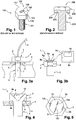
- Taiwanese patent TW 1310810 proposes a screw 100, represented on the Figure 1 formed of a threaded cylindrical body 101 and a head 102 having a strain gauge 103 on the lateral wall 104 of said head, the gauge 103 being connected by a cable 105 to processing and display means 106 disposed on the upper face 107 of the screw head 102.
- the end user can thus periodically check that the clamping force remains adequate over time.
- the gauge 103 may be damaged by the clamping means during tightening, such as a key.
- a screw 200 shown on the Figure 2 formed of a threaded cylindrical body 201 and a head 202, comprising at least one strain gauge 203 disposed in an annular groove 204 formed on the lower face 205 of the screw head 202 and adjacent to the cylindrical body 201.
- the gauge or gauges 203 may transmit their measured values to a display device external to the screw, either wired by a cable passing through a hole drilled in the screw head 202, or wirelessly, in which case each gauge 203 incorporates electronics with wireless transmission.
- the present invention aims to solve the problems encountered with the measuring gage screws described above, and thus to provide a screw whose measurement of internal stresses is easier and more reliable for better control in time of the clamping provided by the screws and whose gauges are less likely to be damaged.
- the present invention relates to a screw having a screw head and a threaded cylindrical body, the screw head being provided with strain gauges arranged to deform with the deformation of the screw head, in order to measure a constraint. internal to the screw, said gauges being for this purpose connected or able to be connected to a power supply and to determining means for determining the value of at least one internal stress to the screw from the deformations of said gauges, characterized in that the screw head has, on its upper face, a conical hole whose axis of revolution is aligned with the axis of revolution of the cylindrical body of the screw, and that said gauges are disposed on the wall of the conical hole so as to deform with the deformation of the conical hole, said gauges being oriented so as to measure at least one type of stress internal to the screw selected from the traction and the shear in order to know the forces present in the cylindrical body.
- the solution according to the present invention allows an amplification of the strain of the strain gauges when the screw is under stress, to make more reliable the tensile and / or shear stress measurements, without parasitic measures, the gauges being otherwise protected deterioration.
- the screw head is provided with four strain gauges, said for traction, two gauges are each arranged with their main direction of measurement aligned with a generatrix of said conical hole, the two generatrices being diametrically opposed , and the two other gauges are each arranged with their main measurement direction on a circle formed at the intersection of the wall of said conical hole and an imaginary plane parallel to the upper face of the screw head, and are distributed at equidistant from each other on the circumference of said circle, preferably each being centered on a respective one of said two generatrices, the four gauges being connected by a Wheatstone bridge connected or adapted to be connected to the power supply and to the means of determination, said gauges for measuring the internal tensile stress when shear is not applied in the screw head.
- the screw head is provided with four first strain gauges, known as tensile gauges, and four second strain gauges, also known as tensile gauges, said first gauges are each arranged with their main direction of tension. measurement aligned with a generator of said conical hole and are distributed at a uniform angle between them, and said second gauges are each arranged with their main measurement direction on a circle formed at the intersection of the wall of said conical hole and a plane imaginary parallel to the upper face of the screw head, and are distributed equidistant from each other on the circumference of said circle, said first gauges forming two groups of gauges each comprising two first adjacent gauges connected electrically in series and said second gauges forming two other groups of gauges each comprising two adjacent gauges connected electrically in series, the four groups of gauges being connected by a Wheatstone bridge connected or adapted to be connected to the power supply and the determination means, said first and second gauges for measuring the internal tensile stress in the screw head in order to know the forces present
- the screw head is a hexagonal head and the main direction of measurement of each of said first gauges forms an angle of between 30 and 10 degrees, preferably 15 degrees, with respect to a generator connecting the top of the conical hole to a point of intersection of the generator circle of the conical hole with a line segment connecting two opposing vertices of the hexagon defining the contour of the upper face of the screw head.
- Each second gauge may be located between the main measurement directions of two adjacent first gauges.
- each second gauge is centered on the main direction of measurement of a corresponding one of said first gages.
- the term "centered" means that the main direction of measurement of the first gauge passes through the center of the second gauge, taken in the main direction of measurement of the latter.
- each second gauge is in one piece with the corresponding first gauge, in the form of a double gauge rosette.
- the screw head is provided with four strain gage gauges, the first and third gages being arranged each parallel to two generatrices located at 45 ° on either side of a main generator of the conical hole, the two other gauges being arranged each parallel to two generatrices located at 45 ° on either side of another main generatrix of the conical hole diametrically opposite said main generator of the conical hole, the four gauges being connected by a Wheatstone bridge connected or adapted to be connected to the power supply and to the determination means, said gauges making it possible to measure the internal shear stress in the screw head in order to know the forces present in the cylindrical body.
- the conical hole has a height less than or equal to that of the screw head.
- the apex angle of the cone is between 70 and 150 degrees, preferably between 75 and 120 degrees, and most preferably is 90 degrees.
- the four shear gauges can be arranged in conjunction with the strain gauges, or be disposed without the strain gauges.
- a groove is formed on the lower surface of the screw head and concentrically and adjacent to the threaded cylindrical body.
- strain gauges may be connected or adapted to be connected to the power supply and the wired determination means.
- the strain gauges may be connected or adapted to be connected to the power supply and the wireless determination means, the gauges being connected to a first near-field communication (NFC) type wireless transmitter / receiver, and the power supply and the determining means being connected to a second NFC-type wireless transmitter / receiver, the first and second transceivers being able to transfer energy and information wirelessly between them.
- NFC near-field communication
- FIG. 3a a principle view of a screw 1 according to the present invention, which has a head 2 and a threaded cylindrical body 3 and which connects a first part 4 having a through hole 5 and a second piece 6 having a threaded blind hole 7 whose thread corresponds to the thread of the threaded body 3.
- the screw 1 can undergo a tensile stress according to the arrow T, a shear stress according to the two-way arrow C, or the two joint stresses.
- the screw 1 comprises a set of strain gauges 8 connected to a power supply and internal stress determining means (s) (not shown).
- the means for determining internal stress are here a voltmeter for measuring the voltage across a Wheatstone bridge, which bridge will be described in more detail in the following description.
- the gauge assembly 8 may be connected to said power supply and to said determining means, either by a wire connection 9, as shown in FIG. Figure 3a either by a wireless link as shown on the Figure 3b .
- the gauge assembly 8 is connected to a first NFC-type wireless transmitter / receiver 8a (near-field communication), and the power supply 8b and the determination means 8c are connected to a second transmitter NFC type 8d wireless receiver, the first and second transceivers 8a, 8d being able to transfer energy and information wirelessly between them.
- the first wireless transmitter / receiver 8a is formed of an amplifier 8e, an NFC chip 8f and a circular antenna 8g surrounding the amplifier 8e, these elements being integrated in the gage assembly 8, and forming the upper part of the latter.
- the second wireless transceiver 8b includes similar elements (not shown).
- the advantage of such wireless communication is to allow, during the lifetime of the screw 1, to place at any time the second transmitter / receiver 8b near the screw 1 to read the value of stress of the screw 1, so as to verify that the latter is tight, and proceed to a tightening in the opposite case.
- the gauge assembly 8 comprises strain gauges which are installed in a conical hole 10 made on the upper face 2a of the head 2 and whose axis of revolution is aligned with that of the cylindrical body 3 , so that the hole 10 is made in the center of the head 2.
- the gauges are fixed in the conical hole 10 by gluing.
- the bonding must be done accurately, so that the deformation of the gauge reflects the deformation of the piece as close as possible.
- the height of the conical hole 10 is here substantially equal to that of the screw head 2, but it can be lower.
- the angle at the top of the conical hole 10 is here 90 degrees. It is emphasized here that this dimension of the conical hole 10 is not limiting and is given solely by way of example, and the appended figures are non-limiting schematic views.
- the conical hole 10 makes it possible to amplify the deformations experienced by the gauges when the screw head 2 is stressed.
- the gauges are disposed on a side face of the screw head, or in a groove formed on its underside.
- Gauges placed in the conical hole 10 will be more deformed than the screw gauges of the prior art, because the bottom of the conical hole 10 will be pulled down in the case of a pull down, and therefore the generatrix of the conical hole 10 will extend more significantly than a side face of the screw head or throat.
- the arrangement of the gauges in the conical hole 10 makes it possible, if necessary, to control the latter in an easy and fast manner, which is not possible with the screws of the prior art.
- the placement of the gauges in the conical hole 10 protects them. Indeed, contrary to the prior art, the gauges can not be damaged by a tool or by too much tightening.
- the first transmitter / receiver when present, may be attached to the wall of the conical hole 10, for example by gluing the edges of the NFC chip against said wall, or otherwise may be glued to the upper face 2a of the head 2, covering the conical hole 10, in the case of screws of smaller size.
- a groove 11 is formed on the lower face 2b of the head 2 and is adjacent to the threaded cylindrical body 3.
- the groove 11 ensures that the support of the screw head 2 is not too close to the threaded cylindrical body 3 and that the deformation of the screw head 2 does not depend on its installation. Indeed, the hole 5 of the support 4 in which the screw passes is generally slightly wider than the screw, to facilitate the passage thereof. There is therefore a clearance between the screw and said hole, and the screw can be positioned offset in said hole, so that the game is not the same over the entire circumference of the hole.
- the bearing surface of the screw head depends on said clearance, and if the bearing surface decreases, the stresses will be greater, and the deformation greater.
- the groove 11 makes it possible to ensure that the same bearing surface 11a bears on the support 4, whatever the position of the screw 1 in the hole 5.
- strain gauges in particular four strain gauges 12a-12d, are fixed in the conical hole 10.
- Each of the gauges 12a-12d has a main direction of measurement, represented by the orientation of the schematic segment forming each of the gauges 12a-12d on the Figures 4 and 5 .
- the main direction of measurement of a gauge is here the longitudinal direction of the gauge, according to which the gauge lengthens or is shortened.
- First two gauges 12a, 12c are each arranged with their main direction of measurement aligned with a generatrix of said conical hole 10, said generatrices being diametrically opposed.
- Two second gauges 12b-12d are each arranged with their main measurement direction on a circle formed at the intersection of the wall of said conical hole 10 and an imaginary plane parallel to the upper face 2a of the screw head 2, and are diametrically opposed.
- the four gauges 12a-12d are electrically connected according to a Wheatstone bridge 13 powered electrically by the two-point power supply 13a and 13b, the Wheatstone bridge 13 being in contact with each other. further connected to the internal stress determining means (s), here a voltmeter, in two points 13c and 13d.
- s internal stress determining means
- R1-R4 are used to define the value of the resistance of the gauges 12a-12d.
- R 1 R 12 at ;
- R 2 R 12 b ;
- R 3 R 12 c ;
- R 4 R 12 d .
- the gauges 12a-12d In the initial state, that is to say when no stress is applied on the screw 1, the gauges 12a-12d have the same resistance value.
- each of the gauges has the same resistance value R in the initial state.
- the resistance value of an extensometry gauge is proportional to its length, and increases as the gauge lengthens and decreases as the gauge narrows.
- the resistance value of the first gages 12a, 12c increases by a given value, for example A
- the resistance value of the second gages 12b, 12d decreases by a given value, for example -B.
- Equation (3) is not satisfied, and a non-zero voltage Vs is measured.
- the tensile stress is related to the voltage Vs by a linear mathematical relation.
- the tensile stress is proportional to the measured voltage.
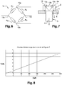
- FIG. 8 An example of a voltage / stress calibration line is shown on the Figure 8 .
- different traction forces are applied known on the screw 1 and the voltage at the Wheatstone bridge 13 is measured for each one.
- the tensile force can be known by knowing the voltage measured at the bridge 13.
- the screw head 2 When applying a shear force alone to the screw 1, the screw head 2 shortens in the shear direction and elongates in the direction orthogonal to the shear. In such a case, the first gauges 12a, 12c are only very slightly deformed and the second gauges 12b, 12d lengthen or shorten depending on the shear direction.
- the gauges 12b and 12d shorten.
- the resistance value of the gauges 12a, 12c is not modified, or will be negligible, and the resistance value of the second gauges 12b, 12d decreases by the same value -C.
- Equation (3) is not satisfied, and a non-zero voltage Vs is measured, whereby shear is measured.
- the screw according to the first embodiment makes it possible to accurately measure a tensile stress, under the condition that no shear is present.
- the two constraints can be exerted, and the second and third embodiments make it possible respectively to measure a tensile stress and a shear stress, even in the case where these two constraints are exerted simultaneously.
- the screw head 2 has eight gauges 14a-14h strain gauge fixed in the conical hole 10.
- Each of the gauges 14a-14h has a main direction of measurement, represented by the orientation of the schematic segment forming each of the gauges 14a-14h on the Figures 9 .
- first gauges 14a-14d are each arranged with their main measurement direction aligned with a generator of said conical hole 10 and are distributed at a uniform angle between them.
- the measuring direction of one of the gauges 14a-14d is at right angles to that of the two gauges 14a-14d which are adjacent to it, when the screw 1 is seen from above, as on the Figure 9 .
- gauges 14e-14h are each arranged with their main direction of measurement on a circle formed at the intersection of the wall of said conical hole 10 and an imaginary plane parallel to the upper face 2a of the screw head 2, and are distributed equidistant from each other on the circumference of said circle.
- the gauges 14e-14h are opposed two by two and one of the gauges 14e-14h is a quarter of a circle of the two gauges 14e-14h which are adjacent thereto.
- the second gauges are fixed perpendicularly to said generators and centered on the latter. In other words, each of the generators crosses a second gauge, perpendicularly and at its center.
- the screw head 2 is a hexagonal head
- the main direction of measurement of each of said first gauges 14a-14d forms an angle of 15 degrees with respect to a generator connecting the apex of the conical hole 10 at a point of intersection of the generator circle of the conical hole 10 with a line segment connecting two opposite vertices of the hexagon defining the contour of the upper face 2a of the screw head 2.
- the direction main measuring one of the first gauges 14a-14d is rotated 15 degrees relative to a straight line passing through two opposite peaks of the hexagon forming the head 2 of the screw 1, taking the top of the conical hole 10 as center of rotation. Since each of the first gauges 14a-14d is 90 degrees from its two adjacent gauges, each of the gauges 14a-14d is oriented at 15 degrees from a straight line passing through two opposite vertices of the hexagon forming the screw head 2 .
- the second gauges 14e-14h are each placed in a zone of the same inertia as the others.
- the second gauges 14e-14h may be arranged near the first gauges 14a-14d, as shown in FIG. Figure 9 , or be in one piece with them, as shown on the Figure 10 where four double gauge rosettes are used.
- the orientation at 15 degrees allows to have the same inertia on each gauge 14a-14h during tightening. Indeed, the fact that the screw head 2 is of hexagonal shape induced during its tightening constraints of different intensities depending on the measurement location.
- the quantity of material to be displaced is greater, and consequently, the moment of inertia to be applied is greater than on a mediator of two opposite sides of the head 2.
- the orientation at 15 degrees thus makes it possible to obtain an identical moment of inertia for each of the gauges 14a-14h.
- the device 8 may also comprise a temperature sensor 14t, which makes it possible to measure the temperature variations of the screw head 2.
- a change in temperature causes expansion or contraction of the material forming the screw head 2, which lengthens or retracts the gauges 12a-12h, and a temperature variation causes a change in the elasticity of the material forming the screw 1.
- the sensitivity of the gauge also depends on the temperature, as the thermal drift of the zero in which the resistance of a gauge increases with temperature, in the absence of stress. It is therefore necessary to take into account the temperature during the measurement.
- the compensation of the resistance value as a function of the temperature can be done in the amplifier 8e, in the case of a wireless measurement, or in the determination means, in the case of a wire measurement. In both cases, the temperature compensation follows a rule established empirically or by learning.
- gauges 14a-14h which gauges 14a-14h are connected in series in pairs, so that the resistance values of these add together, and form groups of gauges connected by a Wheatstone bridge 13.
- Such a device 8 can be implemented, for example, on screws of size M4 according to ISO 4017, namely a screw whose distance between two opposite sides of the hexagon forming the head is 7 mm.
- R 1 R 14 at + R 14 b ;
- R 2 R 14 e + R 14 f ;
- R 3 R 14 c + R 14 d ;
- R 4 R 14 g + R 14 h .
- the first gauges 14a-14d are elongated while the second gauges 14e-14h shorten.
- the resistance value of the first gages 14a-14d increases by a value D
- the resistance value of the second gages 14e-14h decreases by a value -E.
- Equation (3) is not satisfied, and a non-zero voltage Vs is measured, and thus the tensile stress can be deduced therefrom.
- the screw head 2 When applying a shear force alone to the screw 1, the screw head 2 shortens in the shear direction and elongates in the direction orthogonal to the shear. In such a case, the first gauges 14a-14d are only slightly deformed and the second gauges 14e-14h lengthen or shorten depending on the shear direction.
- the gauges 14e and 14g when shear oriented along an axis passing through the gauges 14e and 14g is applied, the latter elongate and the gauges 14f and 14h shorten.
- the resistance value of the first gauges 14a-14d is not modified, that of the gauges 14e and 14g increases and the gauges 14f and 14h decreases.
- the resistance value of the gauges 14e and 14g increases by the same value F and the resistance value of the second gauges 14f and 14h decreases by the same value - G.
- equation (3) is satisfied, and no voltage is measured.
- the screw 1 is tightened with a nut 16 between a first plate 4 having a through hole 5 and a second plate 17 having a through hole 18.
- Each of the gauges 15a-15d has a main direction of measurement, represented by the orientation of the schematic segment forming each of the gauges 15a-15d on the Figures 11 to 13 .
- the first and second gauges 15a, 15b are arranged so that their main directions of measurement are at 45 ° on either side of a first generatrix of the conical hole 10, and the third and fourth gauges 15c, 15d are disposed of the same way at 45 ° on either side of another generatrix diametrically opposed to said first generatrix of the conical hole 10.
- the four gauges 15a-15d are electrically connected according to the Wheatstone bridge 13.
- the screw head 2 When a tensile force T is exerted on the screw 1, in particular during its tightening, the screw head 2 is deformed in such a manner that its upper surface 2a becomes concave. In such a case, the gauges 15a-15d all elongate, and of the same value.
- Equation (3) is satisfied, and a zero voltage Vs is measured.
- the screw according to the third mode of Therefore, the embodiment of the present invention does not make it possible to measure a tensile stress alone.
- the gauges 15a and 15b are elongated and the gauges 15c and 15d shorten.
- the resistance value of the gauges 15a and 15b increases by the same value I and the resistance value of the second gauges 15c and 15d decreases by the same value J.
- the gauges 15a and 15c are elongated and the gauges 15b and 15d shorten.
- the resistance value of the gauges 15a and 15c increases by the same value I and the resistance value of the second gauges 15b and 15d decreases by the same value J.
- the screw 1 according to the third embodiment therefore makes it possible to measure a shear by knowing its direction beforehand in order to measure the stresses it exerts in the screw head 2.
- the screw 1 may comprise both strain gauges 12a-12d or 14a-14h, and shear gauges 15a-15d, each connected by a Wheatstone bridge 13 as described above.
Description
La présente invention concerne le domaine du serrage des vis et porte, en particulier, sur une vis ayant des moyens permettant de connaître les contraintes présentes dans celle-ci pendant et/ou après le serrage.The present invention relates to the field of tightening screws and door, in particular, a screw having means for knowing the stresses present therein during and / or after tightening.
Lors de l'opération de serrage d'une vis, il peut être nécessaire de connaître avec précision les efforts présents dans la vis. Cela est également utile dans la maintenance des assemblages réalisés à l'aide de vis, puisque l'on souhaite s'assurer que le serrage reste adéquat au cours du temps.During the tightening operation of a screw, it may be necessary to know precisely the forces present in the screw. This is also useful in the maintenance of assemblies made with screws, since it is desired to ensure that the clamping remains adequate over time.
En effet, un serrage trop intense peut détériorer la vis ou la pièce dans laquelle elle est vissée, et un serrage trop faible peut conduire à la désolidarisation de la vis par rapport à ladite pièce. Le serrage se traduit par l'application d'une force de traction sur la vis, dans la direction longitudinale de cette dernière, qui se traduit ainsi en des contraintes de traction internes à la vis et en un allongement de celle-ci.Indeed, too tight a tightening can deteriorate the screw or the part in which it is screwed, and too tight a tightening can lead to the separation of the screw relative to said part. Clamping results in the application of a tensile force on the screw, in the longitudinal direction of the latter, which is thus translated into tensile stresses internal to the screw and an elongation thereof.
En outre, la vis peut être soumise à un cisaillement par les pièces auxquelles elle est vissée, par exemple du fait d'un mauvais alignement des trous dans lesquelles est vissée la vis ou tout simplement des sollicitations que subissent en fonctionnement lesdites pièces. Ce cisaillement créera des contraintes de cisaillement internes à la vis, lesquelles peuvent conduire à un desserrage ou, dans le pire des cas, à une rupture de la vis.In addition, the screw may be subjected to shear by the parts to which it is screwed, for example because of a misalignment of the holes in which the screw is screwed or simply solicitations experienced in operation said parts. This shear will create shear stresses internal to the screw, which can lead to loosening or, in the worst case, to a rupture of the screw.
Les dispositifs classiques de mesure du couple de serrage, à savoir les outils de serrage comprenant un dynamomètre, permettent de serrer une vis avec un couple appliqué à la vis connu de manière précise. Cependant, le couple appliqué à la vis ne correspond pas obligatoirement au serrage réalisé, notamment en raison du fait que ce dernier dépend de la friction, des matériaux, etc. Ces dispositifs ne permettent donc pas de garantir le serrage.Conventional devices for measuring the tightening torque, namely clamping tools comprising a dynamometer, used to tighten a screw with a torque applied to the screw known precisely. However, the torque applied to the screw does not necessarily correspond to the tightening achieved, in particular because of the fact that the latter depends on friction, materials, etc. These devices do not therefore ensure tightness.
Ainsi, pour garantir le serrage, on cherchera à mesurer les contraintes internes de traction dans la vis, plutôt que le couple de serrage. En effet, le serrage de deux pièces l'une contre l'autre correspond directement à l'effort de traction appliqué à la vis, et donc à l'allongement de cette dernière.Thus, to guarantee the tightening, one will try to measure the internal tensile stresses in the screw, rather than the tightening torque. Indeed, the clamping of two parts against each other corresponds directly to the tensile force applied to the screw, and therefore to the elongation of the latter.
On connaît l'utilisation de dispositifs de mesure des contraintes intégrés dans la vis. Ils permettent notamment d'obtenir une valeur de l'allongement de la vis à l'aide de techniques particulières, telles que les techniques par ultrasons ou par barreau témoin.The use of devices for measuring the stresses integrated in the screw is known. They allow in particular to obtain a value of the elongation of the screw using special techniques, such as ultrasonic techniques or bar test.
Cependant, ces techniques présentent un ou plusieurs parmi les inconvénients suivants :
- les équipements mis en oeuvre sont complexes,
- la vis est creusée jusque dans la partie filetée dans le cas du barreau témoin, ce qui induit une fragilisation,
- la mesure est fonction de la longueur de la vis et les efforts sont à calculer en fonction de chaque type de vis, et
- la technique n'est adaptable qu'à des vis de relativement grande taille et ne permet de mesurer qu'un effort de traction.
- the equipment used is complex,
- the screw is hollowed into the threaded portion in the case of the control bar, which induces embrittlement,
- the measurement is a function of the length of the screw and the forces are to be calculated according to each type of screw, and
- the technique is adaptable only to screws of relatively large size and only measures a tensile force.
Afin de résoudre ces problèmes, le brevet taïwanais
L'utilisateur final peut ainsi périodiquement contrôler que l'effort de serrage reste adéquat au cours du temps.The end user can thus periodically check that the clamping force remains adequate over time.
Avec une telle vis 100, la jauge 103 peut être endommagée par le moyen de serrage lors du serrage, tel qu'une clé. En outre, il est nécessaire de creuser un trou dans la vis pour faire passer le câble 105, et les déformations détectées sont de faible intensité, et donc difficiles à évaluer avec précision.With such a
Afin de résoudre ces problèmes, la demande de brevet américain
La ou les jauges 203 peuvent transmettre leurs valeurs mesurées à un dispositif d'affichage externe à la vis, soit de manière filaire par un câble passant par un trou percé dans la tête de vis 202, soit de manière sans fil, auquel cas chaque jauge 203 intègre une électronique avec transmission sans fil.The gauge or
Cependant, cette vis présente plusieurs inconvénients :
- une communication sans fil entre les jauges et le dispositif d'affichage externe est difficile étant donné que les jauges sont prisonnières entre la vis et les pièces auxquelles elle est vissée, qui sont généralement métalliques et qui empêchent donc les transmissions ;
- les jauges ne sont que faiblement déformées pendant le serrage et il est donc nécessaire d'avoir une forte déformation de la tête pour obtenir un signal mesurable ;
- les jauges sont placées sous la tête, dans la zone de celle-ci où la pression de serrage est exercée, et peuvent donc être facilement détériorées ;
- les jauges sont rendues inaccessibles une fois le serrage effectué ; et
- des contraintes parasites pour la détermination de l'effort de serrage, telles que le cisaillement, peuvent participer à la déformation des jauges, de sorte que l'on ne mesure pas correctement l'effort de serrage réellement appliqué, lequel correspond à une déformation des jauges due uniquement à la contrainte de traction dans la vis le long de sa direction longitudinale.
- wireless communication between the gauges and the external display device is difficult since the gauges are trapped between the screw and the parts to which it is screwed, which are generally metallic and which thus prevent transmissions;
- the gauges are only slightly deformed during tightening and it is therefore necessary to have a strong deformation of the head to obtain a measurable signal;
- the gauges are placed under the head, in the zone thereof where the clamping pressure is exerted, and can therefore easily be deteriorated;
- the gauges are made inaccessible once tightening is done; and
- parasitic stresses for the determination of the clamping force, such as shear, can participate in the deformation of the gauges, so that the actual applied clamping force, which corresponds to a deformation of gauges due solely to the tensile stress in the screw along its longitudinal direction.
La présente invention vise à résoudre les problèmes rencontrés avec les vis à jauges de mesure décrites ci-dessus, et ainsi proposer une vis dont la mesure des contraintes internes est plus aisée et plus fiable pour un meilleur contrôle dans le temps du serrage assuré par la vis et dont les jauges sont moins susceptibles d'être détériorées.The present invention aims to solve the problems encountered with the measuring gage screws described above, and thus to provide a screw whose measurement of internal stresses is easier and more reliable for better control in time of the clamping provided by the screws and whose gauges are less likely to be damaged.
La présente invention a pour objet une vis ayant une tête de vis et un corps cylindrique fileté, la tête de vis étant munie de jauges d'extensométrie disposées de façon à se déformer avec la déformation de la tête de vis, afin de mesurer une contrainte interne à la vis, lesdites jauges étant à cet effet reliées ou aptes à être reliées à une alimentation électrique et à des moyens de détermination pour déterminer la valeur d'au moins une contrainte interne à la vis à partir des déformations desdites jauges, caractérisée par le fait que la tête de vis présente, sur sa face supérieure, un trou conique dont l'axe de révolution est aligné avec l'axe de révolution du corps cylindrique de la vis, et que lesdites jauges sont disposées sur la paroi du trou conique de façon à se déformer avec la déformation du trou conique, lesdites jauges étant orientées de façon à mesurer au moins un type de contrainte interne à la vis choisi parmi la traction et le cisaillement afin de connaître les efforts présents dans le corps cylindrique.The present invention relates to a screw having a screw head and a threaded cylindrical body, the screw head being provided with strain gauges arranged to deform with the deformation of the screw head, in order to measure a constraint. internal to the screw, said gauges being for this purpose connected or able to be connected to a power supply and to determining means for determining the value of at least one internal stress to the screw from the deformations of said gauges, characterized in that the screw head has, on its upper face, a conical hole whose axis of revolution is aligned with the axis of revolution of the cylindrical body of the screw, and that said gauges are disposed on the wall of the conical hole so as to deform with the deformation of the conical hole, said gauges being oriented so as to measure at least one type of stress internal to the screw selected from the traction and the shear in order to know the forces present in the cylindrical body.
La solution selon la présente invention permet une amplification de la déformation des jauges d'extensométrie lorsque la vis est sous contrainte, pour rendre plus fiable les mesures des contraintes de traction et/ou de cisaillement, sans mesures parasites, les jauges étant par ailleurs protégées de la détérioration.The solution according to the present invention allows an amplification of the strain of the strain gauges when the screw is under stress, to make more reliable the tensile and / or shear stress measurements, without parasitic measures, the gauges being otherwise protected deterioration.
Selon un premier mode de réalisation particulier, la tête de vis est munie de quatre jauges d'extensométrie, dites pour traction, deux jauges sont disposées chacune avec leur direction principale de mesure alignée avec une génératrice dudit trou conique, les deux génératrices étant diamétralement opposées, et les deux autres jauges sont disposées chacune avec leur direction principale de mesure sur un cercle formé à l'intersection de la paroi dudit trou conique et d'un plan imaginaire parallèle à la face supérieure de la tête de vis, et sont réparties à équidistance les unes des autres sur la circonférence dudit cercle, en étant de préférence chacune centrée sur l'une respective desdites deux génératrices, les quatre jauges étant reliées par un pont de Wheatstone relié ou apte à être relié à l'alimentation électrique et aux moyens de détermination, lesdites jauges permettant la mesure de la contrainte interne de traction lorsqu'un cisaillement n'est pas appliqué dans la tête de vis.According to a first particular embodiment, the screw head is provided with four strain gauges, said for traction, two gauges are each arranged with their main direction of measurement aligned with a generatrix of said conical hole, the two generatrices being diametrically opposed , and the two other gauges are each arranged with their main measurement direction on a circle formed at the intersection of the wall of said conical hole and an imaginary plane parallel to the upper face of the screw head, and are distributed at equidistant from each other on the circumference of said circle, preferably each being centered on a respective one of said two generatrices, the four gauges being connected by a Wheatstone bridge connected or adapted to be connected to the power supply and to the means of determination, said gauges for measuring the internal tensile stress when shear is not applied in the screw head.
Selon un deuxième mode de réalisation, la tête de vis est munie de quatre premières jauges d'extensométrie, dites pour traction, et de quatre secondes jauges d'extensométrie, également dites pour traction, lesdites premières jauges sont disposées chacune avec leur direction principale de mesure alignée avec une génératrice dudit trou conique et sont réparties selon un angle uniforme entre elles, et lesdites secondes jauges sont disposées chacune avec leur direction principale de mesure sur un cercle formé à l'intersection de la paroi dudit trou conique et d'un plan imaginaire parallèle à la face supérieure de la tête de vis, et sont réparties à équidistance les unes des autres sur la circonférence dudit cercle, lesdites premières jauges formant deux groupes de jauges comprenant chacun deux premières jauges adjacentes reliées électriquement en série et lesdites secondes jauges formant deux autres groupes de jauges comprenant chacun deux secondes jauges adjacentes reliées électriquement en série, les quatre groupes de jauges étant reliés par un pont de Wheatstone relié ou apte à être relié à l'alimentation électrique et aux moyens de détermination, lesdites premières et secondes jauges permettant la mesure de la contrainte interne de traction dans la tête de vis afin de connaître les efforts présents dans le corps cylindrique.According to a second embodiment, the screw head is provided with four first strain gauges, known as tensile gauges, and four second strain gauges, also known as tensile gauges, said first gauges are each arranged with their main direction of tension. measurement aligned with a generator of said conical hole and are distributed at a uniform angle between them, and said second gauges are each arranged with their main measurement direction on a circle formed at the intersection of the wall of said conical hole and a plane imaginary parallel to the upper face of the screw head, and are distributed equidistant from each other on the circumference of said circle, said first gauges forming two groups of gauges each comprising two first adjacent gauges connected electrically in series and said second gauges forming two other groups of gauges each comprising two adjacent gauges connected electrically in series, the four groups of gauges being connected by a Wheatstone bridge connected or adapted to be connected to the power supply and the determination means, said first and second gauges for measuring the internal tensile stress in the screw head in order to know the forces present in the cylindrical body.
De préférence, la tête de vis est une tête hexagonale et la direction principale de mesure de chacune desdites premières jauges forme un angle compris entre 30 et 10 degrés, de préférence de 15 degrés, par rapport à une génératrice reliant le sommet du trou conique à un point d'intersection du cercle générateur du trou conique avec un segment de droite reliant deux sommets opposés de l'hexagone définissant le contour de la face supérieure de la tête de vis.Preferably, the screw head is a hexagonal head and the main direction of measurement of each of said first gauges forms an angle of between 30 and 10 degrees, preferably 15 degrees, with respect to a generator connecting the top of the conical hole to a point of intersection of the generator circle of the conical hole with a line segment connecting two opposing vertices of the hexagon defining the contour of the upper face of the screw head.
Chaque seconde jauge peut être située entre les directions principales de mesure de deux premières jauges adjacentes.Each second gauge may be located between the main measurement directions of two adjacent first gauges.
De préférence, chaque seconde jauge est centrée sur la direction principale de mesure de l'une, correspondante, desdites premières jauges. On entend par « centrée » que la direction principale de mesure de la première jauge passe par le centre de la seconde jauge, pris dans la direction principale de mesure de cette dernière.Preferably, each second gauge is centered on the main direction of measurement of a corresponding one of said first gages. The term "centered" means that the main direction of measurement of the first gauge passes through the center of the second gauge, taken in the main direction of measurement of the latter.
De façon encore davantage préférée, chaque seconde jauge est d'un seul tenant avec la première jauge correspondante, sous la forme d'une rosette à jauge double.Even more preferably, each second gauge is in one piece with the corresponding first gauge, in the form of a double gauge rosette.
Selon un troisième mode de réalisation particulier, la tête de vis est munie de quatre jauges d'extensométrie, dites pour cisaillement, les première et troisième jauges étant disposées chacune parallèlement à deux génératrices situées à 45° de part et d'autre d'une génératrice principale du trou conique, les deux autres jauges étant disposées chacune parallèlement à deux génératrices situées à 45° de part et d'autre d'une autre génératrice principale du trou conique diamétralement opposée à ladite génératrice principale du trou conique, les quatre jauges étant reliées par un pont de Wheatstone relié ou apte à être relié à l'alimentation électrique et aux moyens de détermination, lesdites jauges permettant la mesure de la contrainte interne de cisaillement dans la tête de vis afin de connaître les efforts présents dans le corps cylindrique.According to a third particular embodiment, the screw head is provided with four strain gage gauges, the first and third gages being arranged each parallel to two generatrices located at 45 ° on either side of a main generator of the conical hole, the two other gauges being arranged each parallel to two generatrices located at 45 ° on either side of another main generatrix of the conical hole diametrically opposite said main generator of the conical hole, the four gauges being connected by a Wheatstone bridge connected or adapted to be connected to the power supply and to the determination means, said gauges making it possible to measure the internal shear stress in the screw head in order to know the forces present in the cylindrical body.
De préférence, le trou conique a une hauteur inférieure ou égale à celle de la tête de vis.Preferably, the conical hole has a height less than or equal to that of the screw head.
De préférence, l'angle du sommet du cône est compris entre 70 et 150 degrés, de préférence entre 75 et 120 degrés, et, de la façon que l'on préfère le plus, est de 90 degrés.Preferably, the apex angle of the cone is between 70 and 150 degrees, preferably between 75 and 120 degrees, and most preferably is 90 degrees.
Les quatre jauges pour cisaillement peuvent être disposées conjointement avec les jauges pour traction, ou être disposées sans les jauges pour traction.The four shear gauges can be arranged in conjunction with the strain gauges, or be disposed without the strain gauges.
De préférence, une gorge est formée sur la surface inférieure de la tête de la vis et de manière concentrique et adjacente au corps cylindrique fileté.Preferably, a groove is formed on the lower surface of the screw head and concentrically and adjacent to the threaded cylindrical body.
Les jauges d'extensométrie peuvent être reliées ou aptes à être reliées à l'alimentation électrique et aux moyens de détermination par liaison filaire.The strain gauges may be connected or adapted to be connected to the power supply and the wired determination means.
Les jauges d'extensométrie peuvent être reliées ou aptes à être reliées à l'alimentation électrique et aux moyens de détermination de manière sans fil, les jauges étant reliées à un premier émetteur/récepteur sans fil de type communication en champ proche (NFC), et l'alimentation électrique et les moyens de détermination étant reliés à un second émetteur/récepteur sans fil de type NFC, les premier et second émetteurs/récepteurs étant aptes à transférer entre eux de l'énergie et des informations de manière sans fil.The strain gauges may be connected or adapted to be connected to the power supply and the wireless determination means, the gauges being connected to a first near-field communication (NFC) type wireless transmitter / receiver, and the power supply and the determining means being connected to a second NFC-type wireless transmitter / receiver, the first and second transceivers being able to transfer energy and information wirelessly between them.
Pour mieux illustrer l'objet de la présente invention, on va en décrire ci-après, à titre indicatif et non limitatif, plusieurs modes de réalisation particuliers avec référence au dessin annexé.To better illustrate the object of the present invention, will be described below, by way of indication and not limited to several particular embodiments with reference to the accompanying drawing.
Sur ce dessin :
- les
Figures 1 sont des vues, respectivement perspective et en coupe verticale, de vis à jauges de mesure de contraintes selon l'état antérieur de la technique ;et 2 - la
Figure 3a est une vue schématique d'une vis selon la présente invention, reliant deux pièces, et reliée par câble à une alimentation électrique et aux moyens de détermination ; - la
Figure 3b est une vue schématique d'une vis selon la présente invention, reliée de manière sans fil à une alimentation électrique et aux moyens de détermination ; - la
Figure 4 est un schéma de principe, en coupe verticale, d'une vis selon la présente invention ; - la
Figure 5 est un schéma de principe d'agencement des jauges, en vue de dessus, de la vis selon le premier mode de réalisation ; - la
Figure 6 est un schéma électrique du pont de Wheatstone reliant les jauges de la vis selon l'invention ; - la
Figure 7 est un schéma de principe, en coupe verticale, d'une vis selon le premier mode de réalisation de la présente invention, subissant une contrainte de traction due à l'application d'un couple de serrage ; - la
Figure 8 représente une courbe d'étalonnage d'une vis selon le premier mode de réalisation ; - la
Figure 9 est un schéma de principe d'agencement des jauges, en vue de dessus, d'une vis selon un deuxième mode de réalisation de la présente invention ; - la
Figure 10 est une vue schématique de dessus d'une vis selon le deuxième mode de réalisation, avec le câblage des jauges, les jauges étant représentées à l'horizontale pour des raisons de commodité de représentation ; - la
Figure 11 est un schéma de principe, en vue de côté et en coupe partielle, d'une vis selon un troisième mode de réalisation de la présente invention, munie de jauges d'extensométrie pour mesurer le cisaillement ; - la
Figure 12 est un schéma de principe, en vue de dessus, de la vis selon le troisième mode de réalisation ; et - la
Figure 13 est un schéma de principe, en vue de côté et en coupe partielle, de la vis selon le troisième mode de réalisation, subissant une contrainte de cisaillement.
- the
Figures 1 and 2 are views, respectively perspective and in vertical section, screws to strain gauges according to the prior art; - the
Figure 3a is a schematic view of a screw according to the present invention, connecting two parts, and connected by cable to a power supply and the determination means; - the
Figure 3b is a schematic view of a screw according to the present invention, wirelessly connected to a power supply and the determination means; - the
Figure 4 is a schematic diagram, in vertical section, of a screw according to the present invention; - the
Figure 5 is a schematic diagram of arrangement of the gauges, in top view, of the screw according to the first embodiment; - the
Figure 6 is an electrical diagram of the Wheatstone bridge connecting the gauges of the screw according to the invention; - the
Figure 7 is a schematic diagram, in vertical section, of a screw according to the first embodiment of the present invention, undergoing a tensile stress due to the application of a tightening torque; - the
Figure 8 represents a calibration curve of a screw according to the first embodiment; - the
Figure 9 is a schematic diagram of arrangement of the gauges, in top view, of a screw according to a second embodiment of the present invention; - the
Figure 10 is a schematic top view of a screw according to the second embodiment, with the wiring of the gauges, the gauges being shown horizontally for the sake of convenience of representation; - the
Figure 11 is a block diagram, in side view and in partial section, of a screw according to a third embodiment of the present invention, provided with strain gauges for measuring shear; - the
Figure 12 is a schematic diagram, in top view, of the screw according to the third embodiment; and - the
Figure 13 is a schematic diagram, in side view and in partial section, of the screw according to the third embodiment, undergoing shear stress.
Si l'on se réfère tout d'abord à la
La vis 1 peut subir une contrainte de traction selon la flèche T, une contrainte de cisaillement selon la flèche à double sens C, ou les deux contraintes conjointes.The
La vis 1 comprend un ensemble à jauges d'extensométrie 8 relié à une alimentation électrique et à des moyens de détermination de contrainte(s) interne(s) (non représentés).The
Les moyens de détermination de contrainte(s) interne(s) sont ici un voltmètre permettant de mesurer la tension aux bornes d'un pont de Wheatstone, pont qui sera décrit plus en détail dans la suite de la description.The means for determining internal stress (es) are here a voltmeter for measuring the voltage across a Wheatstone bridge, which bridge will be described in more detail in the following description.
L'ensemble à jauges 8 peut être relié à ladite alimentation électrique et auxdits moyens de détermination, soit par une liaison filaire 9, comme représenté sur la
Plus précisément, le premier émetteur/récepteur sans fil 8a est formé d'un amplificateur 8e, d'une puce NFC 8f et d'une antenne circulaire 8g entourant l'amplificateur 8e, ces éléments étant intégrés dans l'ensemble à jauges 8, et formant la partie supérieure de ce dernier. Le second émetteur/récepteur sans fil 8b comprend des éléments similaires (non représentés).More specifically, the first wireless transmitter /
L'avantage d'une telle communication sans fil est de permettre, au cours de la vie en service de la vis 1, de placer à n'importe quel moment le second émetteur/récepteur 8b près de la vis 1 pour lire la valeur de contrainte de la vis 1, afin de vérifier ainsi que cette dernière est bien serrée, et procéder à un resserrage dans le cas contraire.The advantage of such wireless communication is to allow, during the lifetime of the
Si l'on se réfère à la
Les jauges sont fixées dans le trou conique 10 par un collage. Le collage doit être réalisé de manière précise, pour que la déformation de la jauge reflète la déformation de la pièce de la manière la plus proche possible.The gauges are fixed in the
La hauteur du trou conique 10 est ici sensiblement égale à celle de la tête de vis 2, mais elle peut être inférieure. L'angle au sommet du trou conique 10 est ici de 90 degrés. On souligne ici que cette dimension du trou conique 10 n'est pas limititative et est donnée uniquement à titre d'exemple, ainsi que les Figures annexées sont des vues schématiques non limitatives.The height of the
Le trou conique 10 permet d'amplifier les déformations subies par les jauges lorsque la tête de vis 2 subit une contrainte.The
En effet, dans l'état antérieur de la technique, les jauges sont disposées sur une face latérale de la tête de vis, ou dans une gorge formée sur sa face inférieure.Indeed, in the prior art, the gauges are disposed on a side face of the screw head, or in a groove formed on its underside.
Dans le cas d'une traction, une jauge disposée sur une face latérale de la tête de vis ne subit qu'un très faible raccourcissement, puisque le bas de ladite face prend appui sur le support sur lequel la vis est serrée, la tête s'écrasant très faiblement à cet endroit, et une jauge disposée dans la gorge subit une faible déformation même en présence d'une contrainte d'intensité élevée, cette partie de la vis subissant peu de déformations à cet endroit.In the case of traction, a gauge disposed on a lateral face of the screw head undergoes only a very low shortening, since the bottom of said face bears on the support on which the screw is tightened, the head crashing very weakly at this point, and a gauge disposed in the groove undergoes a small deformation even in the presence of a constraint of high intensity, this part of the screw undergoing little deformation at this point.
Des jauges placées dans le trou conique 10 seront davantage déformées que les jauges des vis de l'état antérieur de la technique, car le fond du trou conique 10 sera tiré vers le bas dans le cas d'une traction orientée vers le bas, et par conséquent la génératrice du trou conique 10 va s'allonger de manière plus importante qu'une face latérale de la tête de vis ou que la gorge.Gauges placed in the
De plus, la disposition des jauges dans le trou conique 10 permet, si nécessaire, de contrôler ces dernières de manière aisée et rapide, ce qui n'est pas réalisable avec les vis de l'état antérieur de la technique.In addition, the arrangement of the gauges in the
En outre, le placement des jauges dans le trou conique 10 permet de protéger ces dernières. En effet, contrairement à l'état antérieur de la technique, les jauges ne peuvent pas être endommagées ni par un outil, ni par un serrage trop important.In addition, the placement of the gauges in the
Le premier émetteur/récepteur, lorsqu'il est présent, pourra être fixé à la paroi du trou conique 10, par exemple par collage des bords de la puce NFC contre ladite paroi, ou autrement pourra être collé sur la face supérieure 2a de la tête 2, en recouvrant le trou conique 10, dans le cas de vis de plus petite taille.The first transmitter / receiver, when present, may be attached to the wall of the
Une gorge 11 est réalisée sur la face inférieure 2b de la tête 2 et est adjacente au corps cylindrique fileté 3.A
La gorge 11 permet d'assurer que l'appui de la tête de vis 2 ne se fasse pas trop près du corps cylindrique fileté 3 et que la déformation de la tête de vis 2 ne dépende pas de son installation. En effet, le trou 5 du support 4 dans lequel passe la vis est généralement légèrement plus large que la vis, afin de faciliter le passage de celle-ci. Il existe donc un jeu entre la vis et ledit trou, et la vis peut être positionnée de manière décalée dans ledit trou, de telle sorte que le jeu n'est pas le même sur toute la circonférence du trou. La surface d'appui de la tête de vis dépend dudit jeu, et si la surface d'appui diminue, les contraintes seront plus importantes, et la déformation plus grande.The
On voit donc que la déformation dépend de la surface de la tête de vis 2 en appui sur le support 4.It can thus be seen that the deformation depends on the surface of the
La gorge 11 permet d'assurer qu'une même surface d'appui 11a sera en appui sur le support 4, quelle que soit la position de la vis 1 dans le trou 5.The
Sur la
Si l'on se réfère aux
Chacune des jauges 12a-12d a une direction principale de mesure, représentée par l'orientation du segment schématisé formant chacune des jauges 12a-12d sur les
Deux premières jauges 12a, 12c sont disposées chacune avec leur direction principale de mesure alignée avec une génératrice dudit trou conique 10, lesdites génératrices étant diamétralement opposées.First two
Deux secondes jauges 12b-12d sont disposées chacune avec leur direction principale de mesure sur un cercle formé à l'intersection de la paroi dudit trou conique 10 et d'un plan imaginaire parallèle à la face supérieure 2a de la tête de vis 2, et sont diamétralement opposées.Two
Les quatre jauges 12a-12d, et plus généralement les jauges de l'ensemble à jauges 8, sont reliées électriquement selon un pont de Wheatstone 13 alimenté électriquement par l'alimentation électrique en deux points 13a et 13b, le pont de Wheatstone 13 étant en outre relié aux moyens de détermination de contrainte(s) interne(s), ici un voltmètre, en deux points 13c et 13d.The four
Afin de simplifier la lecture, on utilise les termes R1-R4 pour définir la valeur de la résistance des jauges 12a-12d. On a ainsi le groupe d'équations (1) suivant : ![]()
![]()
![]()
![]()
L'équation (2) relie les valeurs de résistance R1-R4 avec les tensions d'entrée et de sortie respectivement Ve (tension appliquée entre 13a et 13b) et Vs (tension mesurée entre 13c et 13d), du pont de Wheatstone pont 13 : ![]()
![]()
A l'état initial, c'est-à-dire lorsqu'aucune contrainte n'est appliquée sur la vis 1, les jauges 12a-12d ont la même valeur de résistance.In the initial state, that is to say when no stress is applied on the
Ainsi, de manière générale et pour la suite de la description, on considérera que chacune des jauges a une même valeur de résistance R à l'état initial.Thus, in general and for the remainder of the description, it will be considered that each of the gauges has the same resistance value R in the initial state.
Dans le cas présent, R1 = R2 = R3 = R4 = R.In this case, R1 = R2 = R3 = R4 = R.
En remplaçant dans l'équation (2), on obtient : ![]()
![]()
On comprend donc que, comme R2-R2 = 0, on a Vs = 0 quelle que soit Ve. Le pont est alors dit équilibré, dans cet état initial.It is therefore understood that, since R 2 -R 2 = 0, we have Vs = 0 regardless of Ve. The bridge is then said to be balanced, in this initial state.
Inversement, on comprend que le pont est équilibré lorsque l'équation (3) est satisfaite : ![]()
![]()
On va maintenant étudier le comportement des jauges et les mesures associées pour différents cas de contrainte de traction.We will now study the behavior of the gauges and the associated measurements for different cases of tensile stress.
Si l'on se réfère à la
La valeur de résistance d'une jauge d'extensométrie est proportionnelle à sa longueur, et augmente lorsque la jauge s'allonge et diminue lorsque la jauge se rétrécit.The resistance value of an extensometry gauge is proportional to its length, and increases as the gauge lengthens and decreases as the gauge narrows.
Ainsi, la valeur de résistance des premières jauges 12a, 12c augmente d'une valeur donnée, par exemple A, et la valeur de résistance des secondes jauges 12b, 12d diminue d'une valeur donnée, par exemple -B.Thus, the resistance value of the
En remplaçant dans le groupe d'équations (1), on a donc : R1 = R3 = R + A, et R2 = R4 = R - B.By replacing in the group of equations (1), we have: R1 = R3 = R + A, and R2 = R4 = R - B.
Puis en remplaçant dans l'équation (3), on a : ![]()
![]()
Même dans le cas où les premières jauges s'allongent autant que les secondes jauges raccourcissent, c'est-à-dire avec A=B, et en remplaçant B par A dans (3), on a encore (3) = 4RA ≠ 0.Even if the first gauges lengthen as much as the second gauges shorten, that is to say with A = B, and replacing B by A in (3), we still have (3) = 4RA ≠ 0.
L'équation (3) n'est pas satisfaite, et une tension Vs non nulle est mesurée.Equation (3) is not satisfied, and a non-zero voltage Vs is measured.
On a vérifié expérimentalement que la contrainte de traction est liée à la tension Vs par une relation mathématique linéaire. En d'autres termes, la contrainte de traction est proportionnelle à la tension électrique mesurée.It has been experimentally verified that the tensile stress is related to the voltage Vs by a linear mathematical relation. In other words, the tensile stress is proportional to the measured voltage.
Un exemple de droite d'étalonnage tension/contrainte est représenté sur la
Il est nécessaire d'établir une telle droite d'étalonnage pour chaque type de vis car le coefficient de proportionnalité, à savoir la pente de la droite, est différent pour chaque vis. Il dépend en effet, et entre autres, de la forme précise de la vis 1, de sa longueur, de la taille de la tête de vis 2, et de la position exacte des jauges.It is necessary to establish such a calibration line for each type of screw because the coefficient of proportionality, namely the slope of the line, is different for each screw. It depends, among other things, on the precise shape of the
Ainsi, en pratique, seront fournies à l'utilisateur final la vis et la droite d'étalonnage correspondante, de sorte que l'utilisateur peut connaître la valeur de la contrainte de traction à partir de la valeur de tension fournie par les moyens de détermination de contrainte(s) interne(s).Thus, in practice, will be provided to the end user the screw and the corresponding calibration line, so that the user can know the value of the tensile stress from the voltage value provided by the determination means internal constraint (s).
Lors de l'application d'une force de cisaillement seule sur la vis 1, la tête de vis 2 raccourcit dans la direction de cisaillement et s'allonge dans la direction orthogonale au cisaillement. Dans un tel cas, les premières jauges 12a, 12c ne sont que très faiblement déformées et les secondes jauges 12b, 12d s'allongent ou se raccourcissent en fonction de la direction du cisaillement.When applying a shear force alone to the
En particulier, lorsqu'un cisaillement orienté selon un axe passant par les jauges 12a et 12c est appliqué, les jauges 12b et 12d raccourcissent.In particular, when shear oriented along an axis passing through the
Ainsi, la valeur de résistance des jauges 12a, 12c n'est pas modifiée, ou le sera de manière négligeable, et la valeur de résistance des secondes jauges 12b, 12d diminue d'une même valeur -C.Thus, the resistance value of the
On a donc R2 = R4 = R-C ; et R1 = R3 = R.We therefore have R2 = R4 = R-C; and R1 = R3 = R.
En remplaçant dans l'équation (3), on a : 
L'équation (3) n'est pas satisfaite, et une tension Vs non nulle est mesurée, ce par quoi le cisaillement est mesuré.Equation (3) is not satisfied, and a non-zero voltage Vs is measured, whereby shear is measured.
De la même manière, un cisaillement orienté dans la même direction que les jauges 12b et 12c fera s'allonger celles-ci.In the same way, a shear oriented in the same direction as the
On aura donc R2 = R4 = R+C et (3) = C2-2RC ≠ 0. On obtient donc une valeur de tension qui traduit la contrainte de cisaillement subie par la vis. Cependant, cette mesure est une mesure parasite, et n'est pas le but recherché par la vis selon le premier mode de réalisation de la présente invention.We will thus have R2 = R4 = R + C and (3) = C 2 -2RC ≠ 0. We thus obtain a value of tension which reflects the shear stress undergone by the screw. However, this measurement is a parasitic measure, and is not the aim of the screw according to the first embodiment of the present invention.
Dans le cas de l'application d'une traction conjointement à un cisaillement, par exemple un cisaillement selon un axe passant par les jauges 12a et 12c est appliqué, on observe le comportement suivant des jauges :
- les jauges
12a et 12c s'allongent sous l'effet de la traction, le cisaillement ne produisant qu'une très faible déformation, donc négligeable, de celles-ci, et - les jauges
12b et 12d raccourcissent sous l'effet de la traction et raccourcissent davantage sous l'effet du cisaillement.
- the
gauges - the
gauges
On a donc : ![]()
![]()
![]()
![]()
En reprenant l'équation (3), on obtient : ![]()
![]()
Même dans le cas où les premières jauges s'allongent autant que les secondes jauges raccourcissent sous l'effet de la traction, c'est-à-dire avec A=B, et en remplaçant B par A dans (3), on a encore (3) = 4RA+-C2+2RC-2AC ≠ 0.Even in the case where the first gauges get longer as long as the second gauges shorten under the effect of traction, that is to say with A = B, and replacing B by A in (3), we have still (3) = 4RA + -C 2 + 2RC-2AC ≠ 0.
On constate que l'on mesure donc une valeur de résistance dans lesquelles les composantes dues à la traction et au cisaillement se mélangent.It can be seen that a resistance value is measured in which the components due to traction and shear are mixed.
Ainsi, la vis selon le premier mode de réalisation permet de mesurer de manière précise une contrainte de traction, sous la condition qu'aucun cisaillement n'est présent.Thus, the screw according to the first embodiment makes it possible to accurately measure a tensile stress, under the condition that no shear is present.
En pratique, les deux contraintes peuvent être exercées, et les deuxième et troisième modes de réalisation permettent de mesurer respectivement une contrainte de traction et une contrainte de cisaillement, même dans le cas où ces deux contraintes sont exercées simultanément.In practice, the two constraints can be exerted, and the second and third embodiments make it possible respectively to measure a tensile stress and a shear stress, even in the case where these two constraints are exerted simultaneously.
Si l'on se réfère maintenant aux
Quatre premières jauges 14a-14d sont disposées chacune avec leur direction principale de mesure alignée avec une génératrice dudit trou conique 10 et sont réparties selon un angle uniforme entre elles. En d'autres termes, la direction de mesure de l'une des jauges 14a-14d est à angle droit de celle des deux jauges 14a-14d qui lui sont adjacentes, lorsque la vis 1 est vue de dessus, comme sur la
Quatre secondes jauges 14e-14h sont disposées chacune avec leur direction principale de mesure sur un cercle formé à l'intersection de la paroi dudit trou conique 10 et d'un plan imaginaire parallèle à la face supérieure 2a de la tête de vis 2, et sont réparties à équidistance les unes des autres sur la circonférence dudit cercle. En d'autres termes, les jauges 14e-14h sont opposées deux à deux et l'une des jauges 14e-14h est à un quart de cercle des deux jauges 14e-14h qui lui sont adjacentes.Four
En outre, les secondes jauges sont fixées perpendiculairement auxdites génératrices et centrées sur ces dernières. En d'autre termes, chacune des génératrices croise une seconde jauge, perpendiculairement et en son centre.In addition, the second gauges are fixed perpendicularly to said generators and centered on the latter. In other words, each of the generators crosses a second gauge, perpendicularly and at its center.
On peut également voir sur les
De la même manière, les secondes jauges 14e-14h sont placées chacune dans une zone de même inertie que les autres. Les secondes jauges 14e-14h peuvent être disposées près des premières jauges 14a-14d, comme représenté sur la
L'orientation à 15 degrés permet d'avoir une même inertie sur chaque jauge 14a-14h lors du serrage. En effet, le fait que la tête de vis 2 soit de forme hexagonale induit lors de son serrage des contraintes d'intensités différentes en fonction de l'emplacement de mesure.The orientation at 15 degrees allows to have the same inertia on each
En particulier, sur un axe reliant deux sommets opposés de l'hexagone formant la tête de vis 2, la quantité de matière à déplacer est plus importante, et par conséquent, le moment d'inertie à appliquer est plus important que sur une médiatrice de deux côtés opposés de la tête 2.In particular, on an axis connecting two opposing vertices of the hexagon forming the
Ainsi, les contraintes mesurées par une jauge placée sur ledit axe seront plus faibles que celles mesurées par une jauge placée sur ladite médiatrice.Thus, the stresses measured by a gauge placed on said axis will be smaller than those measured by a gauge placed on said perpendicular bisector.
L'orientation à 15 degrés permet donc d'obtenir un moment d'inertie identique pour chacune des jauges 14a-14h.The orientation at 15 degrees thus makes it possible to obtain an identical moment of inertia for each of the
Le dispositif 8 peut également comprendre un capteur de température 14t, qui permet de mesurer les variations de température de la tête de vis 2.The
En effet, une variation de température entraîne une dilatation ou une contraction de la matière formant la tête de vis 2, ce qui allonge ou rétracte les jauges 12a-12h, et une variation de température entraîne une modification de l'élasticité du matériau formant la vis 1.Indeed, a change in temperature causes expansion or contraction of the material forming the
En outre, la sensibilité de la jauge dépend également de la température, tout comme la dérive thermique du zéro selon laquelle la résistance d'une jauge augmente avec la température, en l'absence de contrainte. Il est donc nécessaire de prendre en compte la température lors de la mesure.In addition, the sensitivity of the gauge also depends on the temperature, as the thermal drift of the zero in which the resistance of a gauge increases with temperature, in the absence of stress. It is therefore necessary to take into account the temperature during the measurement.
La compensation de la valeur de résistance en fonction de la température peut se faire dans l'amplificateur 8e, dans le cas d'une mesure sans fil, ou dans les moyens de détermination, dans le cas d'une mesure filaire. Dans les deux cas, la compensation en température suit une règle établie empiriquement ou par apprentissage.The compensation of the resistance value as a function of the temperature can be done in the
La compensation en soi est une technique bien connue pour corriger la dérive de zéro et de sensibilité des jauges.Compensation in itself is a well-known technique for correcting zero drift and sensitivity of gauges.
Sur la
On peut également voir le câblage reliant les jauges 14a-14h, lesquelles jauges 14a-14h sont reliées en série deux à deux, de telle sorte que les valeurs de résistances de celles-ci s'additionnent, et forment des groupes de jauges reliés par un pont de Wheatstone 13.It is also possible to see the wiring connecting the
Un tel dispositif 8 peut être mis oeuvre, par exemple, sur des vis de taille M4 selon la norme ISO 4017, à savoir une vis dont la distance entre deux côtés opposés de l'hexagone formant la tête est de 7 mm.Such a
En reprenant le groupe d'équations (1), on a ainsi : ![]()
![]()
![]()
![]()
Similairement aux jauges 12a-12d du premier mode de réalisation, lorsqu'une force de traction T est exercée sur la vis 1, les premières jauges 14a-14d s'allongent alors que les secondes jauges 14e-14h raccourcissent.Similarly to the
Ainsi, la valeur de résistance des premières jauges 14a-14d augmente d'une valeur D, et la valeur de résistance des secondes jauges 14e-14h diminue d'une valeur -E.Thus, the resistance value of the
En remplaçant dans le groupe d'équations (1), on a donc : R1 = R3 = 2R + 2D, et R2 = R4 = 2R - 2E.By replacing in the group of equations (1), we have: R1 = R3 = 2R + 2D, and R2 = R4 = 2R - 2E.
Puis en remplaçant dans l'équation (3), on a : ![]()
![]()
Même dans le cas où les premières jauges s'allongent autant que les secondes jauges raccourcissent, c'est-à-dire avec D=E, on a encore (3) = 16RD ≠ 0.Even if the first gauges lengthen as much as the second gauges shorten, that is to say with D = E, we still have (3) = 16RD ≠ 0.
L'équation (3) n'est pas satisfaite, et une tension Vs non nulle est mesurée, et on peut ainsi en déduire la contrainte de traction.Equation (3) is not satisfied, and a non-zero voltage Vs is measured, and thus the tensile stress can be deduced therefrom.
Là encore, on obtient expérimentalement une droite d'étalonnage faisant correspondre la tension mesurée à la contrainte de traction dans la vis, que l'on fournit à l'utilisateur final avec la vis correspondante.Again, experimentally, a calibration line is obtained which matches the measured voltage to the tensile stress in the screw, which is supplied to the end user with the corresponding screw.
Lors de l'application d'une force de cisaillement seule sur la vis 1, la tête de vis 2 raccourcit dans la direction de cisaillement et s'allonge dans la direction orthogonale au cisaillement. Dans un tel cas, les premières jauges 14a-14d ne sont que faiblement déformées et les secondes jauges 14e-14h s'allongent ou se raccourcissent en fonction de la direction du cisaillement.When applying a shear force alone to the
En particulier, lorsqu'un cisaillement orienté selon un axe passant par les jauges 14e et 14g est appliqué, ces dernières s'allongent et les jauges 14f et 14h raccourcissent. Ainsi, la valeur de résistance des premières jauges 14a-14d n'est pas modifiée, celles des jauges 14e et 14g augmente et celle jauges 14f et 14h diminue.In particular, when shear oriented along an axis passing through the
Plus précisément, comme les secondes jauges 14e-14h sont opposées deux à deux, la valeur de résistance des jauges 14e et 14g augmente d'une même valeur F et la valeur de résistance des secondes jauges 14f et 14h diminue d'une même valeur -G.More precisely, since the
On a donc R2 = R4 = R+F + R-G = 2R+F-G ;
et R1 = R3 = 2R.We have R2 = R4 = R + F + RG = 2R + FG;
and R1 = R3 = 2R.
En remplaçant dans l'équation (3), on a : ![]()
![]()
On peut considérer que le cisaillement est parfait ou presque parfait, c'est-à-dire que les jauges 14e et 14g s'allongent autant que les jauges 14f et 14h diminue, soit F=G.It can be considered that the shear is perfect or almost perfect, that is to say that the
Dans un tel cas, l'équation (3) est satisfaite, et aucune tension n'est mesurée.In such a case, equation (3) is satisfied, and no voltage is measured.
Plus généralement, quelles que soient l'orientation et la force du cisaillement, l'équation (3) est satisfaite, et la vis 1 selon le premier mode de réalisation permet donc d'éviter la mesure parasite de la contrainte de cisaillement dans la tête de vis 2, comme expliqué ci-après.More generally, irrespective of the orientation and the force of the shear, equation (3) is satisfied, and the
Dans le cas de l'application d'une traction adjointe à un cisaillement, par exemple un cisaillement selon un axe passant par les jauges 14e et 14g est appliqué, on observe le comportement suivant des jauges :
- les jauges 14a-14d s'allongent d'une valeur D sous l'effet de la traction, le cisaillement ne produisant pas d'effet sur celles-ci,
- les jauges 14e et 14g raccourcissent d'une valeur E sous l'effet de la traction et s'allongent d'une valeur F sous l'effet du cisaillement d'une valeur F, et
- les jauges
14f et 14h raccourcissent d'une valeur E sous l'effet de la traction et raccourcissent encore d'une valeur G sous l'effet du cisaillement.
- the
gauges 14a-14d lengthen by a value D under the effect of traction, the shear having no effect on them, - the
gauges - the
gauges
On a donc : ![]()
![]()
![]()
![]()
En reprenant l'équation (3), on obtient : ![]()
![]()
Comme précédemment, si l'on considère le cisaillement comme parfait ou quasi-parfait, c'est-à-dire que les jauges 14e et 14g s'allongent autant que les jauges 14f et 14h diminue, alors F=G.As before, if we consider the shear as perfect or near-perfect, that is to say that the
On a alors (3) = 8RD+4D2+8RE-4E2 ≠ 0. On constate que les déformations des jauges sous l'effet du cisaillement n'interviennent pas.We then have (3) = 8RD + 4D 2 + 8RE-4E 2 ≠ 0. It can be seen that the deformations of the gages under the effect of shearing do not occur.
Même dans le cas où les premières jauges s'allongent autant que les secondes jauges raccourcissent, c'est-à-dire avec D=E, on a encore (3) = 16RD ≠ 0.Even if the first gauges lengthen as much as the second gauges shorten, that is to say with D = E, we still have (3) = 16RD ≠ 0.
On ne mesure donc bien que la traction à l'aide de la vis 1 selon le deuxième mode de réalisation de la présente invention, la valeur 16RD mesurée étant identique au cas de la traction seule.It is therefore well measured that the traction with the
Si l'on se réfère maintenant aux
La vis 1 est serrée à l'aide d'un écrou 16 entre une première plaque 4 ayant un trou traversant 5 et une seconde plaque 17 ayant un trou traversant 18.The
Chacune des jauges 15a-15d a une direction principale de mesure, représentée par l'orientation du segment schématisé formant chacune des jauges 15a-15d sur les
Les première et deuxième jauges 15a, 15b sont disposées pour que leurs directions principales de mesure soient à 45° de part et d'autre d'une première génératrice du trou conique 10, et les troisième et quatrième jauges 15c, 15d sont disposées de la même manière à 45° de part et d'autre d'une autre génératrice diamétralement opposée à ladite première génératrice du trou conique 10.The first and
Les quatre jauges 15a-15d sont reliées électriquement selon le pont de Wheatstone 13.The four
En reprenant le groupe d'équations (1), on a ainsi : ![]()
![]()
Lorsqu'une force de traction T est exercée sur la vis 1, en particulier pendant son serrage, la tête de vis 2 se déforme d'une manière telle que sa surface supérieure 2a devient concave. Dans un tel cas, les jauges 15a-15d s'allongent toutes, et de la même valeur.When a tensile force T is exerted on the
Ainsi, la valeur de résistance des premières jauges 15a-15d augmente d'une valeur donnée H de telle sorte que R1 = R2 = R3 = R4 = R+H.Thus, the resistance value of the
En remplaçant dans l'équation (3), on a : ![]()
![]()
L'équation (3) est satisfaite, et une tension Vs nulle est mesurée. La vis selon le troisième mode de réalisation de la présente invention ne permet donc pas de mesurer une contrainte de traction seule.Equation (3) is satisfied, and a zero voltage Vs is measured. The screw according to the third mode of Therefore, the embodiment of the present invention does not make it possible to measure a tensile stress alone.
Si l'on se réfère à la
En particulier, lors d'un cisaillement provoqué par le déplacement de la plaque 17 selon une direction 19, les jauges 15a et 15b s'allongent et les jauges 15c et 15d raccourcissent.In particular, during shear caused by the displacement of the
Ainsi, la valeur de résistance des jauges 15a et 15b augmente d'une même valeur I et la valeur de résistance des secondes jauges 15c et 15d diminue d'une même valeur J.Thus, the resistance value of the
On a donc R1 = R3 = R+I et R2 = R4 = R-J.We therefore have R1 = R3 = R + I and R2 = R4 = R-J.
En remplaçant dans l'équation (3), on a : ![]()
![]()
Même dans le cas où on considère le cisaillement comme parfait, c'est-à-dire que les jauges 15a et 15b s'allongent autant que les jauges 15c et 15d raccourcissent, c'est-à-dire avec I=J, et en remplaçant J par I dans (3), on a encore (3) = 4RI ≠ 0.Even in the case where the shear is considered perfect, that is to say that the
Si on considère maintenant un cisaillement provoqué par le déplacement de la plaque 17 selon une direction 20, les jauges 15a et 15c s'allongent et les jauges 15b et 15d raccourcissent.If we now consider a shear caused by the displacement of the
Ainsi, la valeur de résistance des jauges 15a et 15c augmente d'une même valeur I et la valeur de résistance des secondes jauges 15b et 15d diminue d'une même valeur J.Thus, the resistance value of the
On a donc R1 = R2 = R+I et R3 = R4 = R-J.We therefore have R1 = R2 = R + I and R3 = R4 = R-J.
En remplaçant dans l'équation (3), on a : ![]()
![]()
Dans un tel cas l'équation (3) est satisfaite, une tension de sortie Vs nulle est mesurée, et le cisaillement n'est pas mesuré.In such a case equation (3) is satisfied, a zero output voltage Vs is measured, and the shear is not measured.
La vis 1 selon le troisième mode de réalisation permet donc de mesurer un cisaillement en connaissant au préalable sa direction afin de mesurer les contraintes qu'il exerce dans la tête de vis 2.The
Dans le cas d'une traction et d'un cisaillement simultanés, en appliquant le même raisonnement que pour le deuxième mode de réalisation, on comprend que seul le cisaillement sera mesuré.In the case of simultaneous pulling and shearing, applying the same reasoning as for the second embodiment, it is understood that only the shear will be measured.
Là encore, on pourra établir une courbe d'étalonnage pour chaque type de vis.Again, we can establish a calibration curve for each type of screw.
Selon un mode de réalisation particulier, la vis 1 peut comprendre à la fois des jauges pour traction 12a-12d ou 14a-14h, et des jauges pour cisaillement 15a-15d, reliées chacune par un pont de Wheatstone 13 tel que décrit précédemment.According to a particular embodiment, the
Ainsi, une telle vis 1 permet de mesurer à la fois les contraintes de traction et d'un cisaillement dont la direction est connue, dans la tête de vis 2.Thus, such a
Il est bien entendu que les modes de réalisation ci-dessus de la présente invention ont été donnés à titre indicatif et non limitatif et que des modifications pourront y être apportées sans que l'on s'écarte pour autant du cadre de la présente invention.It is understood that the above embodiments of the present invention have been given for information and not limitation and that modifications may be made without departing from the scope of the present invention.
Claims (11)
- A screw (1) having a screw head (2) and a threaded cylindrical body (3), the screw head (2) being provided with strain gauges (12a-12d ; 14a-14h ; 15a-15d) arranged so as to be deformed together with the deformation of the screw head (2), in order to measure a stress within the screw (1), said gauges (12a-12d ; 14a-14h ; 15a-15d) being for this purpose connected or able to be connected to a power supply and to determination means for determining the value of at least one stress within the screw from the deformations of said gauges (12a-12d ; 14a-14h ; 15a-15d), characterised in that the screw head (2) has, on the upper face (2a) thereof, a conical hole (10) having a revolution axis that is aligned with the revolution axis of the cylindrical body (3) of the screw (1), and in that said gauges (12a-12d ; 14a-14h ; 15a-15d) are arranged on the wall of the conical hole (10) so as to be deformed together with the deformation of the conical hole (10), said gauges (12a-12d ; 14a-14h ; 15a-15d) being oriented so as to measure at least one type of stress within the screw (1) selected among the tension and the shearing, in order to determine the stresses within the cylindrical body (3).
- The screw (1) according to claim 1, characterised in that the screw head is provided with four first strain gauges (14a-14d), so-called gauges for tension, and four second strain gauges (14e-14h), also so-called for tension, wherein said first gauges (14a-14d) are each arranged with the main measurement direction thereof being aligned with a generatrix of said conical hole (10) and are distributed with an uniform angle between each other, and said second gauges (14e-14h) are each arranged with the main measurement direction thereof being on a circle formed at the intersection of the wall of said conical hole (10) and an imaginary plane parallel to the upper face (2a) of the screw head (2), and are distributed at equidistance from each other on the circumference of said circle, said first gauges (14a-14d) forming two groups of gauges each comprising two first gauges (14a-14d) that are adjacent and electrically connected in series and said second gauges (14e-14h) forming two other groups of gauges each comprising two second gauges (12e-12h) that are adjacent and electrically connected in series, the four groups of gauges being connected by a Wheatstone bridge (13) connected or able to be connected to the power supply and to the determination means, said first and second gauges (14a-14h) allowing to measure the inner tensile stress in the screw head (2) in order to know the stresses within the cylindrical body (3).
- The screw (1) according to claim 2, characterised in that the screw head (2) is a hexagonal head and the main measurement direction of each of said first gauges (14a-14d) forms an angle between 30 and 10 degrees, preferably 15 degrees, with respect to a generatrix joining the apex of the conical hole (10) to a point of intersection of the generating circle of the conical hole (10) with a line segment joining two opposite apexes of the hexagon defining the outline of the upper face (2a) of the screw head (2).
- The screw (1) according to one of claim 2 and 3, characterised in that each second gauge (14e-14h) is centered on the main measurement direction of a corresponding one of said first gauges (14a-14d).
- The screw (1) according to claim 4, characterised in that each second gauge (14e-14h) is integral with the corresponding first gauge (14a-14d), in the form of a double-gauge rosette.
- The screw (1) according to one of claims 1-5, characterised in that the screw head (2) is provided with four strain gauges (15a-15d), so-called gauges for shearing, the first (15a) and third (15c) gauges each being arranged parallel to two generatrixes located at 45° on either side of a main generatrix of the conical hole (10), the two other gauges (15b, 15d) each being arranged parallel to two generatrixes located at 45° on either side of another main generatrix of the conical hole (10) that is diametrically opposed to said main generatrix of the conical hole (10), the four gauges (15a-15d) being connected by a Wheatstone bridge (18) connected or able to be connected to the power supply and to the determination means, said gauges (15a-15d) allowing to measure the inner shearing stress in the screw head (2) in order to know the stresses within the cylindrical body (3).
- The screw (1) according to claim 1, characterised in that the screw head is provided with four strain gauges (12a-12d), so-called gauges for tension, wherein two gauges (12a, 12c) are each arranged with the main measurement direction thereof being aligned with a generatrix of said conical hole (10), the two generatrixes being diametrically opposed, and the two other gauges (12b, 12d) are each arranged with the main measurement direction thereof being on a circle formed at the intersection of the wall of said conical hole (10) and an imaginary plane parallel to the upper face (2a) of the screw head (2), and are distributed at equidistance from each other on the circumference of said circle, each one being preferably centered on a respective one of said two generatrixes, the four gauges (12a-12d) being connected by a Wheatstone bridge (13) connected or able to be connected to the power supply and to the determination means, said gauges (12a-12d) allowing to measure the inner tensile stress when shearing is not applied in the screw head (2).
- The screw (1) according to one of claims 1-7, characterised in that the conical hole (10) has a height lower than or equal to that of the screw head (2).
- The screw (1) according to one of claims 1-8, characterised in that the angle at the apex of the cone is between 70 and 150 degrees, preferably between 75 and 120 degrees, and most preferably is of 90 degrees.
- The screw (1) according to one of claims 1-9, characterised in that a groove (11) is formed on the lower surface of the head of the screw (2) and in a concentric and adjacent manner with respect to the threaded cylindrical body (3).
- The screw (1) according to one of claims 1-10, characterised in that the strain gauges (12a-12d ; 14a-14h ; 15a-15d) are connected or able to be connected to the power supply and to the determination means in a wireless manner, the gauges (12a-12d ; 14a-14h ; 15a-15d) being connected to a first near field communication (NFC) type wireless transceiver, and the power supply and the determination means being connected to a second NFC type wireless transceiver, the first and second transceivers being able to wirelessly transmit power and information therebetween.
Applications Claiming Priority (2)
| Application Number | Priority Date | Filing Date | Title |
|---|---|---|---|
| FR1556518A FR3038671B1 (en) | 2015-07-09 | 2015-07-09 | SCREW HAVING EXTENSOMETRY GAUGES FOR MEASURING THE TENSION STRESS AND / OR SHEAR SUBJECT (S) THROUGH THE SCREW |
| PCT/FR2016/051749 WO2017006068A1 (en) | 2015-07-09 | 2016-07-08 | Screw instrumented with extensometric strain gauges to measure the tensile and/or shear strain experienced by the screw |
Publications (2)
| Publication Number | Publication Date |
|---|---|
| EP3320219A1 EP3320219A1 (en) | 2018-05-16 |
| EP3320219B1 true EP3320219B1 (en) | 2019-09-11 |
Family
ID=54066111
Family Applications (1)
| Application Number | Title | Priority Date | Filing Date |
|---|---|---|---|
| EP16757275.9A Active EP3320219B1 (en) | 2015-07-09 | 2016-07-08 | Screw instrumented with extensometric strain gauges to measure the tensile and/or shear strain experienced by the screw |
Country Status (7)
| Country | Link |
|---|---|
| US (1) | US10731693B2 (en) |
| EP (1) | EP3320219B1 (en) |
| JP (1) | JP6810142B2 (en) |
| CN (1) | CN107850103B (en) |
| ES (1) | ES2760610T3 (en) |
| FR (1) | FR3038671B1 (en) |
| WO (1) | WO2017006068A1 (en) |
Families Citing this family (10)
| Publication number | Priority date | Publication date | Assignee | Title |
|---|---|---|---|---|
| JP6989667B2 (en) * | 2016-02-12 | 2022-01-05 | 株式会社サンノハシ | Mechanical members used in structures |
| JP6864499B2 (en) * | 2017-02-28 | 2021-04-28 | 株式会社サンノハシ | Fastening bolt device for detecting axial force |
| US11529208B2 (en) | 2018-07-19 | 2022-12-20 | Warsaw Orthopedic, Inc. | Break-off set screw |
| US11298162B2 (en) * | 2018-07-19 | 2022-04-12 | Warsaw Orthopedic, Inc. | Load sensing assembly for a spinal implant |
| US11589905B2 (en) * | 2018-07-19 | 2023-02-28 | Warsaw Orthopedic, Inc. | Set screw sensor placement |
| US11707299B2 (en) * | 2018-07-19 | 2023-07-25 | Warsaw Orthopedic, Inc. | Antenna placement for a digital set screw |
| EP3736552A1 (en) * | 2019-05-08 | 2020-11-11 | Hilti Aktiengesellschaft | Shear sensor collar |
| CN110543036B (en) * | 2019-08-15 | 2021-07-06 | Tcl华星光电技术有限公司 | Liquid crystal display screen |
| CN112179553B (en) * | 2020-09-09 | 2021-06-22 | 西南交通大学 | Method for ultrasonically and synchronously measuring axial force and shearing force of bolt |
| CN113567014A (en) * | 2021-08-05 | 2021-10-29 | 东风汽车集团股份有限公司 | Failure detection method and device for vehicle chassis fastening connection system |
Family Cites Families (17)
| Publication number | Priority date | Publication date | Assignee | Title |
|---|---|---|---|---|
| US2600029A (en) * | 1946-11-12 | 1952-06-10 | Gerotor May Corp | Stress indicating bolt or stud |
| US3201977A (en) * | 1961-02-20 | 1965-08-24 | Kutsay Ali Umit | Strain gauge |
| USRE30183E (en) * | 1976-09-24 | 1980-01-08 | Radio-frequency tuned-circuit microdisplacement transducer | |
| SE424573B (en) * | 1978-11-13 | 1982-07-26 | Atlas Copco Ab | BULK FOR AXIAL POWER TRANSFER |
| DE4410722A1 (en) * | 1994-03-28 | 1995-10-05 | Bosch Gmbh Robert | Non-contact bolt tightening force measurement appts. for quality control |
| US7441462B2 (en) * | 2001-01-29 | 2008-10-28 | Innovation Plus, Llc | Load indicating member with identifying element |
| WO2005111438A1 (en) * | 2004-05-19 | 2005-11-24 | Vibrosystm Inc. | Shear component breakage detection |
| US7293466B2 (en) * | 2005-07-19 | 2007-11-13 | Hitachi, Ltd. | Bolt with function of measuring strain |
| US20080253858A1 (en) * | 2007-04-12 | 2008-10-16 | Chih-Ching Hsieh | Screwing device with function of twisting force measurement |
| US8521448B1 (en) * | 2009-10-21 | 2013-08-27 | The Boeing Company | Structural analysis using measurement of fastener parameters |
| TWI334464B (en) * | 2007-12-13 | 2010-12-11 | Ind Tech Res Inst | Fixing element and inspection system thereof |
| JP2010053927A (en) * | 2008-08-27 | 2010-03-11 | Asahi Electric Works Ltd | Fastening apparatus and system for detecting axial force thereof |
| CN101354300A (en) * | 2008-09-19 | 2009-01-28 | 清华大学 | Bolt strained detection device |
| US8584957B2 (en) * | 2012-01-23 | 2013-11-19 | Silicon Valley Microe Corp. | Intelligent fastener |
| TWI495800B (en) * | 2013-03-06 | 2015-08-11 | Kabo Tool Co | A screw with a locking force |
| JP6324405B2 (en) * | 2013-11-22 | 2018-05-16 | 株式会社サンノハシ | Bolt, nut and strain measurement system |
| CN203745120U (en) * | 2014-01-06 | 2014-07-30 | 潍柴动力股份有限公司 | Bolt stress detection device |
-
2015
- 2015-07-09 FR FR1556518A patent/FR3038671B1/en not_active Expired - Fee Related
-
2016
- 2016-07-08 US US15/742,090 patent/US10731693B2/en active Active
- 2016-07-08 ES ES16757275T patent/ES2760610T3/en active Active
- 2016-07-08 WO PCT/FR2016/051749 patent/WO2017006068A1/en active Application Filing
- 2016-07-08 JP JP2018520032A patent/JP6810142B2/en active Active
- 2016-07-08 CN CN201680039781.2A patent/CN107850103B/en active Active
- 2016-07-08 EP EP16757275.9A patent/EP3320219B1/en active Active
Non-Patent Citations (1)
| Title |
|---|
| None * |
Also Published As
| Publication number | Publication date |
|---|---|
| CN107850103B (en) | 2019-09-13 |
| FR3038671A1 (en) | 2017-01-13 |
| US20180195547A1 (en) | 2018-07-12 |
| JP2018527585A (en) | 2018-09-20 |
| ES2760610T3 (en) | 2020-05-14 |
| CN107850103A (en) | 2018-03-27 |
| FR3038671B1 (en) | 2017-07-21 |
| JP6810142B2 (en) | 2021-01-06 |
| EP3320219A1 (en) | 2018-05-16 |
| WO2017006068A1 (en) | 2017-01-12 |
| US10731693B2 (en) | 2020-08-04 |
Similar Documents
| Publication | Publication Date | Title |
|---|---|---|
| EP3320219B1 (en) | Screw instrumented with extensometric strain gauges to measure the tensile and/or shear strain experienced by the screw | |
| EP2883784B1 (en) | Dynamometric cycle pedal | |
| EP0611193B1 (en) | Device for measuring stress applied on mechanical part and method of fixation | |
| WO1984002577A1 (en) | Ultrasonic method for measuring strains in a bolt or similar part adapted to said method | |
| FR2886403A1 (en) | COLLAR FOR MEASURING THE SIDE DEFORMATION OF A TEST DURING COMPRESSION TESTS, IN PARTICULAR UNIAXIAL OR TRIAXIAL TESTS | |
| FR2852879A1 (en) | TIGHTENING WRENCH | |
| EP1488192B1 (en) | Strain-measuring device | |
| EP0766077B1 (en) | Load sensor for controlling the tightening of pieces joined by a bolt | |
| EP3465123A1 (en) | Sensor for measuring a tightening force applied on a screw-assembly member | |
| CA2983187A1 (en) | Deformation measuring torque meter | |
| WO2000057149A1 (en) | Method and device for measuring a torque exerted on a part subjected to torque and bending loads | |
| CH692559A5 (en) | Sensor compressive stress. | |
| FR3012605A1 (en) | TORSION DEFORMATION MEASURING DEVICE AND / OR TRACTION DEVICE | |
| FR3047681A1 (en) | MECHANICAL CLAMPING PRESS WITH DYNAMOMETER | |
| FR2911528A1 (en) | SCREWDRIVER TOOL INCLUDING ONE OR MORE TORQUE SENSORS MOUNTED FOR MEASURING DEFORMATIONS IN A PLAN PERPENDICULAR TO A AXIS OF REVOLUTION, AND CORRESPONDING SENSOR SUPPORT | |
| FR3021673A1 (en) | INSTRUMENTAL KEY FOR GROUND WIRE EQUIPPED WITH A TIGHTENING TORQUE MEASURING ELEMENT | |
| EP3428055B1 (en) | Method and device for determining the direction and the amplitude of a force applied to a propulsion pod of a boat | |
| FR3005731A1 (en) | DESTRUCTIVE SHOCK SENSOR | |
| FR2845769A1 (en) | Dynamometer for measuring the load or tension applied to a link has a triangular arrangement of three supports for the link which act on a moving body to provide a measurable force proportional to a force applied to the link | |
| FR2708101A1 (en) | Two-way force sensor and application especially to the measurement of a force torsor. | |
| EP3388808B1 (en) | Device for detecting pressure with mechanical uncoupling | |
| FR3138930A1 (en) | Instrumented assembly screw | |
| CH716888B1 (en) | Device for the dynamic characterization of rotating watchmaking tools. | |
| FR2988531A1 (en) | INSTRUMENTED CAM CRIMPING DEVICE | |
| EP0026682A1 (en) | Hydraulic dynamometer |
Legal Events
| Date | Code | Title | Description |
|---|---|---|---|
| STAA | Information on the status of an ep patent application or granted ep patent |
Free format text: STATUS: THE INTERNATIONAL PUBLICATION HAS BEEN MADE |
|
| PUAI | Public reference made under article 153(3) epc to a published international application that has entered the european phase |
Free format text: ORIGINAL CODE: 0009012 |
|
| STAA | Information on the status of an ep patent application or granted ep patent |
Free format text: STATUS: REQUEST FOR EXAMINATION WAS MADE |
|
| 17P | Request for examination filed |
Effective date: 20180209 |
|
| AK | Designated contracting states |
Kind code of ref document: A1 Designated state(s): AL AT BE BG CH CY CZ DE DK EE ES FI FR GB GR HR HU IE IS IT LI LT LU LV MC MK MT NL NO PL PT RO RS SE SI SK SM TR |
|
| AX | Request for extension of the european patent |
Extension state: BA ME |
|
| RIN1 | Information on inventor provided before grant (corrected) |
Inventor name: DEMEOCQ, ETIENNE |
|
| DAV | Request for validation of the european patent (deleted) | ||
| DAX | Request for extension of the european patent (deleted) | ||
| GRAP | Despatch of communication of intention to grant a patent |
Free format text: ORIGINAL CODE: EPIDOSNIGR1 |
|
| STAA | Information on the status of an ep patent application or granted ep patent |
Free format text: STATUS: GRANT OF PATENT IS INTENDED |
|
| INTG | Intention to grant announced |
Effective date: 20190305 |
|
| RAP1 | Party data changed (applicant data changed or rights of an application transferred) |
Owner name: TEXYS.FR Owner name: DEMEOCQ, ETIENNE |
|
| GRAS | Grant fee paid |
Free format text: ORIGINAL CODE: EPIDOSNIGR3 |
|
| GRAA | (expected) grant |
Free format text: ORIGINAL CODE: 0009210 |
|
| STAA | Information on the status of an ep patent application or granted ep patent |
Free format text: STATUS: THE PATENT HAS BEEN GRANTED |
|
| AK | Designated contracting states |
Kind code of ref document: B1 Designated state(s): AL AT BE BG CH CY CZ DE DK EE ES FI FR GB GR HR HU IE IS IT LI LT LU LV MC MK MT NL NO PL PT RO RS SE SI SK SM TR |
|
| REG | Reference to a national code |
Ref country code: GB Ref legal event code: FG4D Free format text: NOT ENGLISH |
|
| REG | Reference to a national code |
Ref country code: CH Ref legal event code: EP |
|
| REG | Reference to a national code |
Ref country code: AT Ref legal event code: REF Ref document number: 1178820 Country of ref document: AT Kind code of ref document: T Effective date: 20190915 |
|
| REG | Reference to a national code |
Ref country code: DE Ref legal event code: R096 Ref document number: 602016020476 Country of ref document: DE Ref country code: IE Ref legal event code: FG4D Free format text: LANGUAGE OF EP DOCUMENT: FRENCH |
|
| REG | Reference to a national code |
Ref country code: NL Ref legal event code: MP Effective date: 20190911 |
|
| REG | Reference to a national code |
Ref country code: LT Ref legal event code: MG4D |
|
| PG25 | Lapsed in a contracting state [announced via postgrant information from national office to epo] |
Ref country code: LT Free format text: LAPSE BECAUSE OF FAILURE TO SUBMIT A TRANSLATION OF THE DESCRIPTION OR TO PAY THE FEE WITHIN THE PRESCRIBED TIME-LIMIT Effective date: 20190911 Ref country code: HR Free format text: LAPSE BECAUSE OF FAILURE TO SUBMIT A TRANSLATION OF THE DESCRIPTION OR TO PAY THE FEE WITHIN THE PRESCRIBED TIME-LIMIT Effective date: 20190911 Ref country code: BG Free format text: LAPSE BECAUSE OF FAILURE TO SUBMIT A TRANSLATION OF THE DESCRIPTION OR TO PAY THE FEE WITHIN THE PRESCRIBED TIME-LIMIT Effective date: 20191211 Ref country code: SE Free format text: LAPSE BECAUSE OF FAILURE TO SUBMIT A TRANSLATION OF THE DESCRIPTION OR TO PAY THE FEE WITHIN THE PRESCRIBED TIME-LIMIT Effective date: 20190911 Ref country code: NO Free format text: LAPSE BECAUSE OF FAILURE TO SUBMIT A TRANSLATION OF THE DESCRIPTION OR TO PAY THE FEE WITHIN THE PRESCRIBED TIME-LIMIT Effective date: 20191211 Ref country code: FI Free format text: LAPSE BECAUSE OF FAILURE TO SUBMIT A TRANSLATION OF THE DESCRIPTION OR TO PAY THE FEE WITHIN THE PRESCRIBED TIME-LIMIT Effective date: 20190911 |
|
| PG25 | Lapsed in a contracting state [announced via postgrant information from national office to epo] |
Ref country code: RS Free format text: LAPSE BECAUSE OF FAILURE TO SUBMIT A TRANSLATION OF THE DESCRIPTION OR TO PAY THE FEE WITHIN THE PRESCRIBED TIME-LIMIT Effective date: 20190911 Ref country code: GR Free format text: LAPSE BECAUSE OF FAILURE TO SUBMIT A TRANSLATION OF THE DESCRIPTION OR TO PAY THE FEE WITHIN THE PRESCRIBED TIME-LIMIT Effective date: 20191212 Ref country code: LV Free format text: LAPSE BECAUSE OF FAILURE TO SUBMIT A TRANSLATION OF THE DESCRIPTION OR TO PAY THE FEE WITHIN THE PRESCRIBED TIME-LIMIT Effective date: 20190911 Ref country code: AL Free format text: LAPSE BECAUSE OF FAILURE TO SUBMIT A TRANSLATION OF THE DESCRIPTION OR TO PAY THE FEE WITHIN THE PRESCRIBED TIME-LIMIT Effective date: 20190911 |
|
| REG | Reference to a national code |
Ref country code: AT Ref legal event code: MK05 Ref document number: 1178820 Country of ref document: AT Kind code of ref document: T Effective date: 20190911 |
|
| PG25 | Lapsed in a contracting state [announced via postgrant information from national office to epo] |
Ref country code: RO Free format text: LAPSE BECAUSE OF FAILURE TO SUBMIT A TRANSLATION OF THE DESCRIPTION OR TO PAY THE FEE WITHIN THE PRESCRIBED TIME-LIMIT Effective date: 20190911 Ref country code: PT Free format text: LAPSE BECAUSE OF FAILURE TO SUBMIT A TRANSLATION OF THE DESCRIPTION OR TO PAY THE FEE WITHIN THE PRESCRIBED TIME-LIMIT Effective date: 20200113 Ref country code: EE Free format text: LAPSE BECAUSE OF FAILURE TO SUBMIT A TRANSLATION OF THE DESCRIPTION OR TO PAY THE FEE WITHIN THE PRESCRIBED TIME-LIMIT Effective date: 20190911 Ref country code: AT Free format text: LAPSE BECAUSE OF FAILURE TO SUBMIT A TRANSLATION OF THE DESCRIPTION OR TO PAY THE FEE WITHIN THE PRESCRIBED TIME-LIMIT Effective date: 20190911 Ref country code: NL Free format text: LAPSE BECAUSE OF FAILURE TO SUBMIT A TRANSLATION OF THE DESCRIPTION OR TO PAY THE FEE WITHIN THE PRESCRIBED TIME-LIMIT Effective date: 20190911 Ref country code: PL Free format text: LAPSE BECAUSE OF FAILURE TO SUBMIT A TRANSLATION OF THE DESCRIPTION OR TO PAY THE FEE WITHIN THE PRESCRIBED TIME-LIMIT Effective date: 20190911 |
|
| REG | Reference to a national code |
Ref country code: ES Ref legal event code: FG2A Ref document number: 2760610 Country of ref document: ES Kind code of ref document: T3 Effective date: 20200514 |
|
| PG25 | Lapsed in a contracting state [announced via postgrant information from national office to epo] |
Ref country code: IS Free format text: LAPSE BECAUSE OF FAILURE TO SUBMIT A TRANSLATION OF THE DESCRIPTION OR TO PAY THE FEE WITHIN THE PRESCRIBED TIME-LIMIT Effective date: 20200224 Ref country code: SK Free format text: LAPSE BECAUSE OF FAILURE TO SUBMIT A TRANSLATION OF THE DESCRIPTION OR TO PAY THE FEE WITHIN THE PRESCRIBED TIME-LIMIT Effective date: 20190911 Ref country code: SM Free format text: LAPSE BECAUSE OF FAILURE TO SUBMIT A TRANSLATION OF THE DESCRIPTION OR TO PAY THE FEE WITHIN THE PRESCRIBED TIME-LIMIT Effective date: 20190911 Ref country code: CZ Free format text: LAPSE BECAUSE OF FAILURE TO SUBMIT A TRANSLATION OF THE DESCRIPTION OR TO PAY THE FEE WITHIN THE PRESCRIBED TIME-LIMIT Effective date: 20190911 |
|
| REG | Reference to a national code |
Ref country code: DE Ref legal event code: R097 Ref document number: 602016020476 Country of ref document: DE |
|
| PLBE | No opposition filed within time limit |
Free format text: ORIGINAL CODE: 0009261 |
|
| STAA | Information on the status of an ep patent application or granted ep patent |
Free format text: STATUS: NO OPPOSITION FILED WITHIN TIME LIMIT |
|
| PG2D | Information on lapse in contracting state deleted |
Ref country code: IS |
|
| PG25 | Lapsed in a contracting state [announced via postgrant information from national office to epo] |
Ref country code: DK Free format text: LAPSE BECAUSE OF FAILURE TO SUBMIT A TRANSLATION OF THE DESCRIPTION OR TO PAY THE FEE WITHIN THE PRESCRIBED TIME-LIMIT Effective date: 20190911 Ref country code: IS Free format text: LAPSE BECAUSE OF FAILURE TO SUBMIT A TRANSLATION OF THE DESCRIPTION OR TO PAY THE FEE WITHIN THE PRESCRIBED TIME-LIMIT Effective date: 20200112 |
|
| 26N | No opposition filed |
Effective date: 20200615 |
|
| PG25 | Lapsed in a contracting state [announced via postgrant information from national office to epo] |
Ref country code: SI Free format text: LAPSE BECAUSE OF FAILURE TO SUBMIT A TRANSLATION OF THE DESCRIPTION OR TO PAY THE FEE WITHIN THE PRESCRIBED TIME-LIMIT Effective date: 20190911 |
|
| PG25 | Lapsed in a contracting state [announced via postgrant information from national office to epo] |
Ref country code: MC Free format text: LAPSE BECAUSE OF FAILURE TO SUBMIT A TRANSLATION OF THE DESCRIPTION OR TO PAY THE FEE WITHIN THE PRESCRIBED TIME-LIMIT Effective date: 20190911 |
|
| REG | Reference to a national code |
Ref country code: CH Ref legal event code: PL |
|
| REG | Reference to a national code |
Ref country code: BE Ref legal event code: MM Effective date: 20200731 |
|
| PG25 | Lapsed in a contracting state [announced via postgrant information from national office to epo] |
Ref country code: LU Free format text: LAPSE BECAUSE OF NON-PAYMENT OF DUE FEES Effective date: 20200708 Ref country code: LI Free format text: LAPSE BECAUSE OF NON-PAYMENT OF DUE FEES Effective date: 20200731 Ref country code: CH Free format text: LAPSE BECAUSE OF NON-PAYMENT OF DUE FEES Effective date: 20200731 |
|
| PG25 | Lapsed in a contracting state [announced via postgrant information from national office to epo] |
Ref country code: BE Free format text: LAPSE BECAUSE OF NON-PAYMENT OF DUE FEES Effective date: 20200731 |
|
| PG25 | Lapsed in a contracting state [announced via postgrant information from national office to epo] |
Ref country code: IE Free format text: LAPSE BECAUSE OF NON-PAYMENT OF DUE FEES Effective date: 20200708 |
|
| PG25 | Lapsed in a contracting state [announced via postgrant information from national office to epo] |
Ref country code: TR Free format text: LAPSE BECAUSE OF FAILURE TO SUBMIT A TRANSLATION OF THE DESCRIPTION OR TO PAY THE FEE WITHIN THE PRESCRIBED TIME-LIMIT Effective date: 20190911 Ref country code: MT Free format text: LAPSE BECAUSE OF FAILURE TO SUBMIT A TRANSLATION OF THE DESCRIPTION OR TO PAY THE FEE WITHIN THE PRESCRIBED TIME-LIMIT Effective date: 20190911 Ref country code: CY Free format text: LAPSE BECAUSE OF FAILURE TO SUBMIT A TRANSLATION OF THE DESCRIPTION OR TO PAY THE FEE WITHIN THE PRESCRIBED TIME-LIMIT Effective date: 20190911 |
|
| PG25 | Lapsed in a contracting state [announced via postgrant information from national office to epo] |
Ref country code: MK Free format text: LAPSE BECAUSE OF FAILURE TO SUBMIT A TRANSLATION OF THE DESCRIPTION OR TO PAY THE FEE WITHIN THE PRESCRIBED TIME-LIMIT Effective date: 20190911 |
|
| REG | Reference to a national code |
Ref country code: ES Ref legal event code: PC2A Owner name: TEXYS INTERNATIONAL Effective date: 20221019 |
|
| REG | Reference to a national code |
Ref country code: DE Ref legal event code: R081 Ref document number: 602016020476 Country of ref document: DE Owner name: TEXYS INTERNATIONAL, FR Free format text: FORMER OWNERS: DEMEOCQ, ETIENNE, ALLIGNY-COSNE, FR; TEXYS.FR, VARENNES-VAUZELLES, FR Ref country code: DE Ref legal event code: R081 Ref document number: 602016020476 Country of ref document: DE Owner name: DEMEOCQ, ETIENNE, FR Free format text: FORMER OWNERS: DEMEOCQ, ETIENNE, ALLIGNY-COSNE, FR; TEXYS.FR, VARENNES-VAUZELLES, FR |
|
| PGFP | Annual fee paid to national office [announced via postgrant information from national office to epo] |
Ref country code: IT Payment date: 20230626 Year of fee payment: 8 Ref country code: GB Payment date: 20230707 Year of fee payment: 8 Ref country code: ES Payment date: 20230802 Year of fee payment: 8 |
|
| PGFP | Annual fee paid to national office [announced via postgrant information from national office to epo] |
Ref country code: FR Payment date: 20230718 Year of fee payment: 8 Ref country code: DE Payment date: 20230726 Year of fee payment: 8 |