EP3320215B1 - Kompakter axiallüfter - Google Patents
Kompakter axiallüfter Download PDFInfo
- Publication number
- EP3320215B1 EP3320215B1 EP16822047.3A EP16822047A EP3320215B1 EP 3320215 B1 EP3320215 B1 EP 3320215B1 EP 16822047 A EP16822047 A EP 16822047A EP 3320215 B1 EP3320215 B1 EP 3320215B1
- Authority
- EP
- European Patent Office
- Prior art keywords
- motor
- fan
- impeller
- shroud
- cup
- Prior art date
- Legal status (The legal status is an assumption and is not a legal conclusion. Google has not performed a legal analysis and makes no representation as to the accuracy of the status listed.)
- Active
Links
- 238000011144 upstream manufacturing Methods 0.000 claims description 25
- 230000004323 axial length Effects 0.000 claims description 19
- 238000001816 cooling Methods 0.000 description 14
- 230000008901 benefit Effects 0.000 description 3
- 230000018109 developmental process Effects 0.000 description 2
- 230000002411 adverse Effects 0.000 description 1
- 230000001419 dependent effect Effects 0.000 description 1
- 239000012530 fluid Substances 0.000 description 1
- 239000007788 liquid Substances 0.000 description 1
- 238000011176 pooling Methods 0.000 description 1
- 230000007704 transition Effects 0.000 description 1
Images


Classifications
-
- F—MECHANICAL ENGINEERING; LIGHTING; HEATING; WEAPONS; BLASTING
- F04—POSITIVE - DISPLACEMENT MACHINES FOR LIQUIDS; PUMPS FOR LIQUIDS OR ELASTIC FLUIDS
- F04D—NON-POSITIVE-DISPLACEMENT PUMPS
- F04D29/00—Details, component parts, or accessories
- F04D29/26—Rotors specially for elastic fluids
- F04D29/32—Rotors specially for elastic fluids for axial flow pumps
- F04D29/325—Rotors specially for elastic fluids for axial flow pumps for axial flow fans
- F04D29/329—Details of the hub
-
- F—MECHANICAL ENGINEERING; LIGHTING; HEATING; WEAPONS; BLASTING
- F04—POSITIVE - DISPLACEMENT MACHINES FOR LIQUIDS; PUMPS FOR LIQUIDS OR ELASTIC FLUIDS
- F04D—NON-POSITIVE-DISPLACEMENT PUMPS
- F04D19/00—Axial-flow pumps
- F04D19/002—Axial flow fans
-
- F—MECHANICAL ENGINEERING; LIGHTING; HEATING; WEAPONS; BLASTING
- F04—POSITIVE - DISPLACEMENT MACHINES FOR LIQUIDS; PUMPS FOR LIQUIDS OR ELASTIC FLUIDS
- F04D—NON-POSITIVE-DISPLACEMENT PUMPS
- F04D25/00—Pumping installations or systems
- F04D25/02—Units comprising pumps and their driving means
- F04D25/06—Units comprising pumps and their driving means the pump being electrically driven
-
- F—MECHANICAL ENGINEERING; LIGHTING; HEATING; WEAPONS; BLASTING
- F04—POSITIVE - DISPLACEMENT MACHINES FOR LIQUIDS; PUMPS FOR LIQUIDS OR ELASTIC FLUIDS
- F04D—NON-POSITIVE-DISPLACEMENT PUMPS
- F04D25/00—Pumping installations or systems
- F04D25/02—Units comprising pumps and their driving means
- F04D25/08—Units comprising pumps and their driving means the working fluid being air, e.g. for ventilation
- F04D25/082—Units comprising pumps and their driving means the working fluid being air, e.g. for ventilation the unit having provision for cooling the motor
-
- F—MECHANICAL ENGINEERING; LIGHTING; HEATING; WEAPONS; BLASTING
- F04—POSITIVE - DISPLACEMENT MACHINES FOR LIQUIDS; PUMPS FOR LIQUIDS OR ELASTIC FLUIDS
- F04D—NON-POSITIVE-DISPLACEMENT PUMPS
- F04D29/00—Details, component parts, or accessories
- F04D29/58—Cooling; Heating; Diminishing heat transfer
- F04D29/5806—Cooling the drive system
Definitions
- the present invention relates generally to axial fans.
- the invention relates to an axial fan which includes an inner-rotor motor and a deepcup rotor which is mounted over the drive end of the motor to thereby substantially reduce the axial length of the fan.
- Prior art axial fans typically use specially designed outer-rotor motors to achieve a compact axial length.
- Two examples of such prior art fans are shown in Figures 1 and 2 .
- the impeller is attached directly to a radially outer portion of the motor which rotates in operation.
- the motor is attached to a stationary support structure located upstream or downstream of the impeller by detachable struts which mount directly to an outer portion of the motor that remains stationary during operation.
- This type of motor is produced in a limited range of sizes by specialty fan manufacturers, but it is not mass-produced by the major electric motor suppliers because of its limited use in non-fan applications and because it typically has a lower efficiency than an inner-rotor motor.
- a suitable outer-rotor motor design may not be commercially available.
- a custom design and development effort requires a significant amount of time and expense which may not be acceptable to today's manufacturers, especially for low to moderate volume applications.
- Use of a pre-existing, mass produced inner-rotor motor avoids the development time and expense of a custom designed motor and also takes advantage of economies of scale to minimize unit costs.
- Fans with inner-rotor motors do exist in the prior art, but they typically are not axially compact.
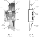
- An example of such a fan is depicted in Figures 3 and 4 .
- the motor is supported by a frame or fan housing with struts that attach to the mounting feet of the motor.
- This fan has a significant axial length which is defined by the combined lengths of the motor, the overhung shaft, the impeller, and an inlet bellmouth. As one can readily see, this prior art inner-rotor motor fan is not axially compact.
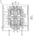
- Applicant's own prior art Tornado TM fan which is depicted in Figures 5 and 6 , is an axially compact fan which incorporates an overhung impeller that includes two small drain holes which allow for fluid communication between the upstream and downstream sides of the impeller cup. These drain holes are provided to prevent pooling of liquids or condensates inside the impeller cup and are not intended to provide reverse flow cooling for the motor.
- This fan uses a custom inner-rotor motor which is connected to the fan shroud by support struts that are integral to the motor housing and fan shroud. Consequently, the motor cannot be readily removed and replaced.
- a pressure difference between the upstream and downstream ends of the impeller 414 induces a portion of the airflow (which is sometimes referred to as a bleed stream and is depicted by the broken-line arrows) to flow upstream through a number of inlet openings 454 in the downstream end of the impeller cup, through the motor 440 and back into the main flowpath F through an annular gap 456 located adjacent the upstream end of the impeller.
- the impeller 414 is driven by an outer-rotor motor 440, the cooling flow passes through the motor rather than around the outside of the motor.
- the bleed stream may adversely impact the main flow stream in the flowpath F.
- FR 2 373 697 discloses a motor-fan unit having features according to the preamble of claim 1.
- the present invention provides an axial fan as defined in claim 1. Further optional features of the invention are specified in the dependent claims.
- the fan may comprise a support structure; a shroud which surrounds the impeller blades; and a number of struts which connect the drive end of the motor to at least one of the support structure and the shroud.
- the motor is supported from said at least one of the support structure and the shroud by the struts.
- each strut may include a first leg which extends generally perpendicularly to a rotational axis of the fan and a second leg which extends generally perpendicularly from the first leg along an outer surface of the motor.
- each first leg may comprise a distal end which is connected to said at least one of the support structure and the shroud and the second leg may comprise a distal end which is connected to the drive end of the motor.
- the struts may be detachably connected to the drive end of the motor and said at least one of the support structure and the shroud.
- the fan may include a support structure; a shroud which surrounds the impeller blades; and a number of struts which connect the motor to at least one of the support structure and the shroud.
- the motor is supported from said at least one of the support structure and the shroud by the struts.
- each strut may include a first leg which extends generally perpendicularly to a rotational axis of the fan and a second leg which extends generally perpendicularly from the first leg along an outer surface of the motor.
- each first leg may comprise a distal end which is connected to said at least one of the support structure and the shroud and the second leg may comprise a distal end which is connected to the motor.
- the struts may be detachably connected to the motor and said at least one of the support structure and the shroud.
- the fan may include means for deflecting the airflow over the upstream end of the impeller cup.
- Such means may comprise, for example, a hub deflector which is secured to one of the motor or a support frame for the motor.
- the hub deflector may comprise a conical ring having an upstream end which is secured to said one of the motor or a support frame for the motor and a downstream end which diverges radially outwardly from the upstream end.
- the downstream end of the impeller cup may include a number of through holes which extend axially therethrough.
- the impeller cup may be configured such that a pressure difference between the upstream and downstream ends of the impeller will induce a portion of the airflow to flow into the through holes, through an annulus between the motor and the impeller cup, and back into the airflow at a location upstream of the impeller cup to thereby cool the drive end of the motor.
- the shroud may comprise a total axial length which is approximately the same as an axial length of the motor.
- the shroud may comprise an inlet bellmouth and an exit diffuser, in which event the total axial length of the shroud is approximately the same as the axial length of the motor.
- the impeller cup may comprise an axial cup length which is approximately 2.3 times an axial blade length of the impeller blades.
- the shroud may comprise an exit diffuser, in which event both the impeller blades and the exit diffuser are incorporated within the axial space claim of the motor.
- the impeller cup may comprise an axial cup length which is approximately 1.7 times an axial blade length of the impeller blades.
- the shroud does not comprise an exit diffuser, and both the impeller blades and the shroud are incorporated within the space claim of the motor.
- the invention is directed to a compact axial fan which incorporates an integrated inner-rotor motor.
- an overhung impeller with an axially deep cup that surrounds the drive end of an inner-rotor motor, preferably detachable support struts that mount to the drive end of the motor, a motor non-drive end which is exposed to the main airflow, and an optional stationary hub deflector which is attached to the motor support frame located between the support struts and the impeller.
- the impeller cup may include through-holes that allow reverse flow cooling to ventilate the cavity between the impeller cup and drive end of the motor.
- the hub deflector guides both the mainstream flow and the reverse cooling flow into the impeller main passage.
- the fan shroud may incorporate an inlet bellmouth and an exit diffuser while remaining axially shorter than the axial length of the motor. The resulting fan provides an axially compact design with good thermal characteristics suitable for use with an inner-rotor motor.
- the present invention is applicable to a variety of air movers. For purposes of brevity, however, it will be described in the context of an exemplary axial cooling fan. Nevertheless, a person of ordinary skill in the art will readily appreciate how the teachings of the present invention can be applied to other types of air movers. Therefore, the following description should not be construed to limit the scope of the present invention in any manner.
- This prior art cooling fan which is indicated generally by reference number 10, is shown to comprise a tubular fan housing 12, a motor 14 which is supported in the fan housing, an impeller 16 which is driven by the motor, and an outlet guide vane assembly 18 which extends radially between the motor 14 and the fan housing 12.
- the fan housing 12 includes a shroud 20 which surrounds the impeller 16, an inlet bellmouth 22 which is formed at the upstream end of the shroud, and an exit diffuser section 24 which is connected to the downstream end of the shroud proximate the outlet guide vane assembly 18.
- the motor 14 includes a motor housing 26, a stator 28 which is mounted in the motor housing, a rotor 30 which is positioned within the stator, and a rotor shaft 32 which is connected to the rotor.
- the rotor shaft 32 is rotatably supported in a front bearing 34 which is mounted in an upstream end of the motor housing 26 and a rear bearing 36 which is mounted in a tail cone 38 that in turn is mounted to the downstream end of the motor housing.
- the impeller 16 includes an impeller cup 40 and a number of impeller blades 42 which extend radially outwardly from the impeller cup.
- the impeller cup 40 may also include a removable nose cone 44 to facilitate mounting the impeller 16 to the rotor shaft 32.
- the outlet guide vane assembly 18 includes an inner ring 46 which is attached to or formed integrally with the motor housing 28, an outer ring 48 which is connected to or formed integrally with the fan housing 12 and a plurality of guide vanes 50 which extend radially between the inner and outer rings.
- the outlet guide vane assembly 18 serves to connect the motor 14 to the fan housing 12.
- the total axial length of the fan 10 is determined by the combined lengths of the inlet bellmouth 22, the impeller, the motor and the exit diffuser section and/or tail cone 38.
- the fan depicted in Figure 8 may not be appropriate due to its total axial length.
- the total axial length of an axial fan is reduced by providing the fan with an inner-rotor motor and an overhung impeller having an axially deep cup that surrounds the drive end of the motor.
- a fan is shown conceptually in Figure 9 .
- the fan of this embodiment which is indicated generally by reference number 100, includes an impeller 102 having an axially deep cup 104 which is mounted to the shaft 106 of an inner-rotor motor 108.
- the impeller cup 104 is configured to surround the drive end 110 of the motor 108, leaving only the non-drive end 112 of the motor exposed to the airflow (which is depicted by the two wide arrows).
- the fan 100 includes a shroud 114 which functions to define a path for the airflow and to provide support for the motor 108; however, in Figure 9 the structure for mounting the motor 108 to the shroud has been omitted for clarity. Thus it may be seen that the total axial length of the fan 100 is basically equal to the length of the motor 108. By selecting an appropriate motor, therefore, the fan 100 may be used in applications affording only limited space for this portion of the cooling arrangement.
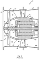
- the fan of this embodiment which is indicated generally by reference number 200, includes an impeller 202 having an axially deep cup 204 which is connected by conventional means to the shaft 206 of an inner-rotor motor 208.
- the impeller cup 204 is configured to surround the drive end 210 of the motor 208, leaving only the non-drive end 212 of the motor exposed to the airflow.
- the fan 200 includes a shroud 214 which may be connected to a support structure for the fan, such as a support plate 216.
- each strut 218 includes a first leg 220 which extends generally perpendicularly to the axis of the fan and a second leg 222 which extends generally perpendicularly from the first leg along the outer surface of the motor 208.
- each first leg 220 has a distal end 224 which is connected to or formed integrally with a mounting pad 226 that in turn is attached to the support plate 216.
- each second leg 222 has a distal end 228 which is connected to the drive end of the motor 208.
- the struts 218 are attached to the drive end of the motor 208 to thereby provide secure and stable support for the motor within the shroud 214.
- the struts 218 are releasably fastened to both the support plate 216 and the motor 208, removal and replacement of the motor is quick and simple.
- the downstream end of the impeller cup 204 may include a number of through holes 232 to facilitate reverse flow cooling of the drive end 210 of the motor 208.
- a pressure difference between the upstream and downstream ends of the impeller 202 will induce a portion of the airflow (depicted in Figure 11 by broken-line arrows) to flow into the through holes 232, through the annulus between the outer surface of the motor 208 and the inner surface of the impeller cup 204, and back into the main airflow at a location upstream of the impeller cup 204.
- the reverse flow will cool the drive end 210 of the motor 208 and lead to improved fan reliability.
- the fan 200 may include means for deflecting the main airflow around the upstream end of the impeller cup 204.
- Such means may comprise, for example, a hub deflector 234 which is attached to a motor support frame located between the support struts and the impeller.
- the hub deflector 234 comprises a conical ring having an upstream end which is secured to the motor support frame and a downstream end which diverges radially outwardly from the upstream end.
- the hub deflector 234 deflects the main airflow (depicted in Figure 11 by solid-line arrows) over the upstream edge of the impeller cup 204.
- the hub deflector 234 creates a smooth flowpath transition for the main airflow between the motor 208 and the impeller cup 204. As shown by the broken-line arrows in Figure 11 , the hub deflector 234 also guides the reverse cooling flow back into the main airflow.
- shroud 214 may incorporate an inlet bellmouth 236 and an exit diffuser 238 within the axial space claim of the motor 208.
- the resulting fan is an axially compact design with good thermal characteristics suitable for use with an inner-rotor motor.
- both the impeller blades and the exit diffuser 238 may be incorporated within the axial space claim of the motor 208. While the exit diffuser 238 improves fan efficiency, in an alternative embodiment of the invention the exit diffuser can be eliminated while still maintaining the same axial length of the shroud 214. In this case, the cup length C may be reduced to approximately 1.7 times the blade length B.
Landscapes
- Engineering & Computer Science (AREA)
- Mechanical Engineering (AREA)
- General Engineering & Computer Science (AREA)
- Physics & Mathematics (AREA)
- Thermal Sciences (AREA)
- Structures Of Non-Positive Displacement Pumps (AREA)
Claims (15)
- Axiallüfter (100, 200), der Folgendes umfasst:einen Motor (108, 208), der ein Antriebsende (110, 210), ein Nicht-Antriebsende (112, 212) und eine sich axial vom Antriebsende (110, 210) aus erstreckende Welle (106, 206) aufweist, undein Laufrad (102, 202), das eine Anzahl von sich radial erstreckenden Laufradschaufeln (240) aufweist;wobei der Motor im Betrieb das Laufrad (102, 202) in Drehung versetzt, um einen Luftstrom zu erzeugen; wobei sich der erzeugte Luftstrom in einer Richtung vom Nicht-Antriebsende (112, 212) des Motors (108, 208) zum Antriebsende (110, 210) des Motors bewegt; wobei das Laufrad ferner einen zylindrischen Laufradbecher (104, 204) aufweist, von dem sich die Laufradschaufeln (240) radial erstrecken, wobei der Laufradbecher ein offenes stromaufwärtiges Ende und ein mit der Welle verbundenes geschlossenes stromabwärtiges Ende aufweist;wobei der Laufradbecher (104, 204) dazu ausgelegt ist, den Motor (108, 208) darin aufzunehmen und das Antriebsende (110, 210) des Motors, jedoch nicht das Nicht-Antriebsende (112, 212) des Motors umgibt;wobei das Nicht-Antriebsende (112, 212) des Motors (108, 208) während des Betriebs des Lüfters (100, 200) dem Luftstrom ausgesetzt ist;und wobei der Motor (108, 208) durch eine Anzahl von Streben (218) gehalten wird;dadurch gekennzeichnet, dass die Streben (218) am Antriebsende (110, 210) mit dem Motor (108, 208) verbunden sind.
- Lüfter (100, 200) gemäß Anspruch 1, ferner umfassend:eine Tragstruktur (216); undeine Ummantelung (114, 214), die die Laufradschaufeln (240) umgibt;wobei die Streben (218) zwischen dem Antriebsende (110, 210) des Motors (108, 208) und mindestens einem von der Tragstruktur und der Ummantelung verbunden sind;wobei der Motor (108, 208) durch die Streben (218) von mindestens einem der Tragstruktur (216) und/oder der Ummantelung (114, 214) getragen wird.
- Lüfter (100, 200) gemäß Anspruch 2, wobei jede Strebe (218) einen ersten Schenkel (220), der sich im Allgemeinen rechtwinklig zu einer Rotationsachse des Lüfters (100, 200) erstreckt, und einen zweiten Schenkel (222) aufweist, der sich im Allgemeinen rechtwinklig vom ersten Schenkel (220) entlang einer Außenfläche des Motors (108, 208) erstreckt.
- Lüfter (100, 200) gemäß Anspruch 2, wobei die Streben (218) abnehmbar mit dem Antriebsende (110, 210) des Motors (108, 208) und dem mindestens einen von der Tragstruktur (216) und der Ummantelung (114, 214) verbunden sind.
- Lüfter (100, 200) gemäß Anspruch 1, ferner umfassend Mittel (234) zum Umlenken des Luftstroms über das stromaufwärts gelegene Ende des Laufradbechers (104, 204) .
- Lüfter gemäß Anspruch 5, wobei das Luftstromumlenkungsmittel einen Nabenumlenker (234) umfasst, der entweder am Motor (108, 208) oder an einem Tragrahmen für den Motor befestigt ist.
- Gebläse gemäß Anspruch 6 (100, 200), wobei der Nabenumlenker einen konischen Ring (234) mit einem stromaufwärtigen Ende, das an dem einen des Motors (108, 208) oder des Tragrahmens für den Motor befestigt ist, und einem stromabwärtigen Ende, das von dem stromaufwärtigen Ende radial nach außen divergiert, umfasst.
- Lüfter (100, 200) gemäß Anspruch 1, wobei das stromabwärtige Ende des Laufradbechers (104, 204) eine Anzahl von Durchgangslöchern (232) aufweist, die sich axial durch ihn hindurch erstrecken.
- Lüfter (100, 200) gemäß Anspruch 8, wobei der Laufradbecher (104, 204) so ausgelegt ist, dass eine Druckdifferenz zwischen einem stromaufwärtigen Ende des Laufrads (102, 202) und einem stromabwärtigen Ende des Laufrads einen Teil des Luftstroms dazu veranlasst, in die Durchgangslöcher (232) zu strömen, durch einen Ringraum zwischen dem Motor (108, 208) und dem Laufradbecher (104, 204) und an einer Stelle stromaufwärts des Laufradbechers (104, 204) zurück in den Luftstrom zu strömen, um dadurch das Antriebsende (110, 210) des Motors (108, 208) zu kühlen.
- Lüfter (100, 200) gemäß Anspruch 2, wobei die Ummantelung (114, 214) eine axiale Gesamtlänge aufweist, die ungefähr gleich der axialen Länge des Motors (108, 208) ist.
- Lüfter (100, 200) gemäß Anspruch 10, wobei die Ummantelung (114, 214) eine Einlassglockenöffnung (236) und einen Auslassdiffusor (238) umfasst und wobei die gesamte axiale Länge der Ummantelung (114, 214) ungefähr gleich der axialen Länge des Motors (108, 208) ist.
- Lüfter (100, 200) gemäß Anspruch 1, wobei der Laufradbecher (104, 204) eine axiale Becherlänge (C) aufweist, die ungefähr das 2,3-fache einer axialen Schaufellänge (B) der Laufradschaufeln (240) beträgt.
- Lüfter (100, 200) gemäß Anspruch 12, wobei der Lüfter ferner eine Ummantelung (114, 214) umfasst, die die Laufradschaufeln (240) umgibt, wobei die Ummantelung einen Austrittsdiffusor (238) umfasst und wobei sowohl die Laufradschaufeln (240) als auch der Austrittsdiffusor (238) in den axialen Raumanspruch des Motors (108, 208) integriert sind.
- Lüfter (100, 200) gemäß Anspruch 1, wobei der Laufradbecher (104, 204) eine axiale Becherlänge (C) aufweist, die ungefähr das 1,7-fache einer axialen Schaufellänge (B) der Laufradschaufeln (240) beträgt.
- Lüfter (100, 200) gemäß Anspruch 14, wobei der Lüfter ferner eine Ummantelung (114, 214) umfasst, die die Laufradschaufeln (240) umgibt, wobei die Ummantelung (114, 214) keinen Ausgangsdiffusor umfasst und wobei sowohl die Laufradschaufeln (240) als auch die Ummantelung (114, 214) in den Raumanspruch des Motors (108, 208) integriert sind.
Applications Claiming Priority (2)
| Application Number | Priority Date | Filing Date | Title |
|---|---|---|---|
| US201562190418P | 2015-07-09 | 2015-07-09 | |
| PCT/US2016/041536 WO2017008025A1 (en) | 2015-07-09 | 2016-07-08 | Compact axial fan |
Publications (3)
| Publication Number | Publication Date |
|---|---|
| EP3320215A1 EP3320215A1 (de) | 2018-05-16 |
| EP3320215A4 EP3320215A4 (de) | 2019-03-13 |
| EP3320215B1 true EP3320215B1 (de) | 2022-02-09 |
Family
ID=57686070
Family Applications (1)
| Application Number | Title | Priority Date | Filing Date |
|---|---|---|---|
| EP16822047.3A Active EP3320215B1 (de) | 2015-07-09 | 2016-07-08 | Kompakter axiallüfter |
Country Status (3)
| Country | Link |
|---|---|
| US (1) | US11525456B2 (de) |
| EP (1) | EP3320215B1 (de) |
| WO (1) | WO2017008025A1 (de) |
Cited By (1)
| Publication number | Priority date | Publication date | Assignee | Title |
|---|---|---|---|---|
| DE102021107355A1 (de) | 2021-03-24 | 2022-09-29 | Ebm-Papst St. Georgen Gmbh & Co. Kg | Schaufelloser Strömungsdiffusor |
Families Citing this family (5)
| Publication number | Priority date | Publication date | Assignee | Title |
|---|---|---|---|---|
| CN208503072U (zh) * | 2018-06-27 | 2019-02-15 | 中强光电股份有限公司 | 风扇模块与电子装置 |
| DE102018211808A1 (de) * | 2018-07-16 | 2020-01-16 | Ziehl-Abegg Se | Ventilator und Leiteinrichtung für einen Ventilator |
| CN109209942B (zh) * | 2018-09-18 | 2020-07-07 | 淮北创之社信息科技有限公司 | 一种双叶片反旋风扇 |
| GB2590627B (en) * | 2019-12-20 | 2022-03-30 | Dyson Technology Ltd | A fan drive assembly |
| CN115313725A (zh) * | 2022-07-29 | 2022-11-08 | 江苏东成工具科技有限公司 | 电机 |
Family Cites Families (24)
| Publication number | Priority date | Publication date | Assignee | Title |
|---|---|---|---|---|
| US3145910A (en) * | 1961-06-05 | 1964-08-25 | Nutone Inc | Spring mount for fan motor of ventilating equipment |
| US3449605A (en) * | 1966-03-30 | 1969-06-10 | Rotron Mfg Co | Cooling arrangement for fanmotor combination |
| US3937192A (en) * | 1974-09-03 | 1976-02-10 | General Motors Corporation | Ejector fan shroud arrangement |
| FR2373697A1 (fr) | 1976-12-13 | 1978-07-07 | Ferodo Sa | Groupe moto-ventilateur a moteur refroidi |
| DE4122018C2 (de) | 1991-07-03 | 1993-12-23 | Licentia Gmbh | Axialgebläse, insbesondere zur Kühlung eines dem Kühler eines Fahrzeugs vorgeordneten Kondensators einer Klimaanlage |
| US5489186A (en) * | 1991-08-30 | 1996-02-06 | Airflow Research And Manufacturing Corp. | Housing with recirculation control for use with banded axial-flow fans |
| US5730583A (en) * | 1994-09-29 | 1998-03-24 | Valeo Thermique Moteur | Axial flow fan blade structure |
| US5772176A (en) * | 1996-03-07 | 1998-06-30 | General Electric Company | Motor mounting system |
| US5944497A (en) * | 1997-11-25 | 1999-08-31 | Siemens Canada Limited | Fan assembly having an air directing member to cool a motor |
| US6856941B2 (en) | 1998-07-20 | 2005-02-15 | Minebea Co., Ltd. | Impeller blade for axial flow fan having counter-rotating impellers |
| DE20307981U1 (de) | 2003-05-22 | 2003-09-11 | Arctic Cooling Gmbh Pfaeffikon | Axialventilator für Computer |
| JP4060252B2 (ja) * | 2003-08-25 | 2008-03-12 | 山洋電気株式会社 | ファンモータ |
| US7244110B2 (en) * | 2003-09-30 | 2007-07-17 | Valeo Electrical Systems, Inc. | Fan hub assembly for effective motor cooling |
| US20060147322A1 (en) * | 2005-01-04 | 2006-07-06 | Asia Vital Component Co., Ltd. | Heat dissipating device in a fan |
| US7687953B2 (en) * | 2005-04-21 | 2010-03-30 | Brose Fahrzeugteile GmbH & Co. Kommanditgesellschaft, Würzburg | Totally integrated engine cooling module for D.C. motors employing fan hub and shroud hub as motor covers |
| US7819641B2 (en) | 2007-03-05 | 2010-10-26 | Xcelaero Corporation | Reverse flow cooling for fan motor |
| US8337154B2 (en) * | 2007-03-05 | 2012-12-25 | Xcelaero Corporation | High efficiency cooling fan |
| ITBO20070380A1 (it) * | 2007-05-30 | 2008-11-30 | Spal Automotive Srl | Unita' di ventilazione |
| CN103591047B (zh) * | 2008-04-15 | 2017-04-12 | 博格华纳公司 | 开放式叶片发动机冷却风扇护罩导向翼瓣 |
| US8313282B1 (en) * | 2009-01-27 | 2012-11-20 | Minebea Co., Ltd. | Compact air-plus-liquid thermal management module |
| DE202010016820U1 (de) * | 2010-12-21 | 2012-03-26 | Ebm-Papst Mulfingen Gmbh & Co. Kg | Diffusor für einen Ventilator sowie Ventilatoranordnung mit einem derartigen Diffusor |
| ITTO20120765A1 (it) | 2012-09-05 | 2014-03-06 | Johnson Electric Asti S R L | Gruppo di ventilazione, particolarmente per uno scambiatore di calore di un veicolo |
| US9951792B2 (en) * | 2013-09-10 | 2018-04-24 | Denso International America, Inc. | Approach for fan motor mounting for ease of serviceability |
| DE112014006367T5 (de) * | 2014-02-14 | 2016-10-27 | Mitsubishi Electric Corporation | Axialströmungsgebläse |
-
2016
- 2016-07-08 EP EP16822047.3A patent/EP3320215B1/de active Active
- 2016-07-08 US US15/743,067 patent/US11525456B2/en active Active
- 2016-07-08 WO PCT/US2016/041536 patent/WO2017008025A1/en active Application Filing
Non-Patent Citations (1)
| Title |
|---|
| None * |
Cited By (1)
| Publication number | Priority date | Publication date | Assignee | Title |
|---|---|---|---|---|
| DE102021107355A1 (de) | 2021-03-24 | 2022-09-29 | Ebm-Papst St. Georgen Gmbh & Co. Kg | Schaufelloser Strömungsdiffusor |
Also Published As
| Publication number | Publication date |
|---|---|
| EP3320215A1 (de) | 2018-05-16 |
| WO2017008025A1 (en) | 2017-01-12 |
| US11525456B2 (en) | 2022-12-13 |
| EP3320215A4 (de) | 2019-03-13 |
| US20180209438A1 (en) | 2018-07-26 |
Similar Documents
| Publication | Publication Date | Title |
|---|---|---|
| EP3320215B1 (de) | Kompakter axiallüfter | |
| JP6851446B2 (ja) | 電気モータ | |
| JP6557650B2 (ja) | モータ及びモータを有するヘアケア機器 | |
| KR100548036B1 (ko) | 축류팬용 안내깃과 그 안내깃을 구비한 축류팬 슈라우드 조립체 | |
| JP6444363B2 (ja) | モータ及びモータを有する手持ち式製品 | |
| US9494162B2 (en) | Axial fan with additional flow channel | |
| US6435828B1 (en) | Split blade radial fan | |
| US8622695B2 (en) | Flow trim for vane-axial fans | |
| EP0955467A3 (de) | Axiallüftereinheit mit einstückigem Gehäuse | |
| US20090155076A1 (en) | Shrouded Dual-Swept Fan Impeller | |
| EP3759794B1 (de) | Bürstenloser motor | |
| US20220106966A1 (en) | Diagonal fan with outlet guide vane device | |
| US20120045323A1 (en) | Fan | |
| BR112016009932B1 (pt) | Compressor de motor sem eixo | |
| CN109209980B (zh) | 一种用于轴流压气机的导流板 | |
| JP6603448B2 (ja) | 遠心インペラ及び遠心ブロワ | |
| CN113294354B (zh) | 贯流风扇、空调器 | |
| EP3156602A1 (de) | Axialströmungsmaschinenschaufel | |
| JP6649790B2 (ja) | 電動送風機 | |
| CN110630536A (zh) | 风扇和电力机械总成及其方法 | |
| JPH0893684A (ja) | 遠心送風機 | |
| JP2005240680A (ja) | 遠心圧縮機 | |
| JP2017180186A (ja) | 車両用遠心送風機 | |
| JP5364261B2 (ja) | ファンおよびエンジンブロワ | |
| KR100707446B1 (ko) | 송풍장치 |
Legal Events
| Date | Code | Title | Description |
|---|---|---|---|
| STAA | Information on the status of an ep patent application or granted ep patent |
Free format text: STATUS: THE INTERNATIONAL PUBLICATION HAS BEEN MADE |
|
| PUAI | Public reference made under article 153(3) epc to a published international application that has entered the european phase |
Free format text: ORIGINAL CODE: 0009012 |
|
| STAA | Information on the status of an ep patent application or granted ep patent |
Free format text: STATUS: REQUEST FOR EXAMINATION WAS MADE |
|
| 17P | Request for examination filed |
Effective date: 20180118 |
|
| AK | Designated contracting states |
Kind code of ref document: A1 Designated state(s): AL AT BE BG CH CY CZ DE DK EE ES FI FR GB GR HR HU IE IS IT LI LT LU LV MC MK MT NL NO PL PT RO RS SE SI SK SM TR |
|
| AX | Request for extension of the european patent |
Extension state: BA ME |
|
| DAV | Request for validation of the european patent (deleted) | ||
| DAX | Request for extension of the european patent (deleted) | ||
| A4 | Supplementary search report drawn up and despatched |
Effective date: 20190211 |
|
| RIC1 | Information provided on ipc code assigned before grant |
Ipc: F04D 25/08 20060101AFI20190205BHEP Ipc: F04D 29/32 20060101ALI20190205BHEP Ipc: F04D 19/00 20060101ALI20190205BHEP Ipc: F04D 25/06 20060101ALI20190205BHEP |
|
| STAA | Information on the status of an ep patent application or granted ep patent |
Free format text: STATUS: EXAMINATION IS IN PROGRESS |
|
| 17Q | First examination report despatched |
Effective date: 20201015 |
|
| GRAP | Despatch of communication of intention to grant a patent |
Free format text: ORIGINAL CODE: EPIDOSNIGR1 |
|
| STAA | Information on the status of an ep patent application or granted ep patent |
Free format text: STATUS: GRANT OF PATENT IS INTENDED |
|
| INTG | Intention to grant announced |
Effective date: 20210621 |
|
| GRAS | Grant fee paid |
Free format text: ORIGINAL CODE: EPIDOSNIGR3 |
|
| STAA | Information on the status of an ep patent application or granted ep patent |
Free format text: STATUS: GRANT OF PATENT IS INTENDED |
|
| GRAA | (expected) grant |
Free format text: ORIGINAL CODE: 0009210 |
|
| STAA | Information on the status of an ep patent application or granted ep patent |
Free format text: STATUS: THE PATENT HAS BEEN GRANTED |
|
| AK | Designated contracting states |
Kind code of ref document: B1 Designated state(s): AL AT BE BG CH CY CZ DE DK EE ES FI FR GB GR HR HU IE IS IT LI LT LU LV MC MK MT NL NO PL PT RO RS SE SI SK SM TR |
|
| RAP1 | Party data changed (applicant data changed or rights of an application transferred) |
Owner name: BASCOM HUNTER TECHNOLOGIES, INC. |
|
| REG | Reference to a national code |
Ref country code: GB Ref legal event code: FG4D |
|
| REG | Reference to a national code |
Ref country code: CH Ref legal event code: EP Ref country code: AT Ref legal event code: REF Ref document number: 1467673 Country of ref document: AT Kind code of ref document: T Effective date: 20220215 |
|
| REG | Reference to a national code |
Ref country code: DE Ref legal event code: R096 Ref document number: 602016069009 Country of ref document: DE |
|
| REG | Reference to a national code |
Ref country code: IE Ref legal event code: FG4D |
|
| REG | Reference to a national code |
Ref country code: LT Ref legal event code: MG9D |
|
| REG | Reference to a national code |
Ref country code: NL Ref legal event code: MP Effective date: 20220209 |
|
| REG | Reference to a national code |
Ref country code: AT Ref legal event code: MK05 Ref document number: 1467673 Country of ref document: AT Kind code of ref document: T Effective date: 20220209 |
|
| PG25 | Lapsed in a contracting state [announced via postgrant information from national office to epo] |
Ref country code: SE Free format text: LAPSE BECAUSE OF FAILURE TO SUBMIT A TRANSLATION OF THE DESCRIPTION OR TO PAY THE FEE WITHIN THE PRESCRIBED TIME-LIMIT Effective date: 20220209 Ref country code: RS Free format text: LAPSE BECAUSE OF FAILURE TO SUBMIT A TRANSLATION OF THE DESCRIPTION OR TO PAY THE FEE WITHIN THE PRESCRIBED TIME-LIMIT Effective date: 20220209 Ref country code: PT Free format text: LAPSE BECAUSE OF FAILURE TO SUBMIT A TRANSLATION OF THE DESCRIPTION OR TO PAY THE FEE WITHIN THE PRESCRIBED TIME-LIMIT Effective date: 20220609 Ref country code: NO Free format text: LAPSE BECAUSE OF FAILURE TO SUBMIT A TRANSLATION OF THE DESCRIPTION OR TO PAY THE FEE WITHIN THE PRESCRIBED TIME-LIMIT Effective date: 20220509 Ref country code: NL Free format text: LAPSE BECAUSE OF FAILURE TO SUBMIT A TRANSLATION OF THE DESCRIPTION OR TO PAY THE FEE WITHIN THE PRESCRIBED TIME-LIMIT Effective date: 20220209 Ref country code: LT Free format text: LAPSE BECAUSE OF FAILURE TO SUBMIT A TRANSLATION OF THE DESCRIPTION OR TO PAY THE FEE WITHIN THE PRESCRIBED TIME-LIMIT Effective date: 20220209 Ref country code: HR Free format text: LAPSE BECAUSE OF FAILURE TO SUBMIT A TRANSLATION OF THE DESCRIPTION OR TO PAY THE FEE WITHIN THE PRESCRIBED TIME-LIMIT Effective date: 20220209 Ref country code: ES Free format text: LAPSE BECAUSE OF FAILURE TO SUBMIT A TRANSLATION OF THE DESCRIPTION OR TO PAY THE FEE WITHIN THE PRESCRIBED TIME-LIMIT Effective date: 20220209 Ref country code: BG Free format text: LAPSE BECAUSE OF FAILURE TO SUBMIT A TRANSLATION OF THE DESCRIPTION OR TO PAY THE FEE WITHIN THE PRESCRIBED TIME-LIMIT Effective date: 20220509 |
|
| PG25 | Lapsed in a contracting state [announced via postgrant information from national office to epo] |
Ref country code: PL Free format text: LAPSE BECAUSE OF FAILURE TO SUBMIT A TRANSLATION OF THE DESCRIPTION OR TO PAY THE FEE WITHIN THE PRESCRIBED TIME-LIMIT Effective date: 20220209 Ref country code: LV Free format text: LAPSE BECAUSE OF FAILURE TO SUBMIT A TRANSLATION OF THE DESCRIPTION OR TO PAY THE FEE WITHIN THE PRESCRIBED TIME-LIMIT Effective date: 20220209 Ref country code: GR Free format text: LAPSE BECAUSE OF FAILURE TO SUBMIT A TRANSLATION OF THE DESCRIPTION OR TO PAY THE FEE WITHIN THE PRESCRIBED TIME-LIMIT Effective date: 20220510 Ref country code: FI Free format text: LAPSE BECAUSE OF FAILURE TO SUBMIT A TRANSLATION OF THE DESCRIPTION OR TO PAY THE FEE WITHIN THE PRESCRIBED TIME-LIMIT Effective date: 20220209 Ref country code: AT Free format text: LAPSE BECAUSE OF FAILURE TO SUBMIT A TRANSLATION OF THE DESCRIPTION OR TO PAY THE FEE WITHIN THE PRESCRIBED TIME-LIMIT Effective date: 20220209 |
|
| PG25 | Lapsed in a contracting state [announced via postgrant information from national office to epo] |
Ref country code: IS Free format text: LAPSE BECAUSE OF FAILURE TO SUBMIT A TRANSLATION OF THE DESCRIPTION OR TO PAY THE FEE WITHIN THE PRESCRIBED TIME-LIMIT Effective date: 20220609 |
|
| PG25 | Lapsed in a contracting state [announced via postgrant information from national office to epo] |
Ref country code: SM Free format text: LAPSE BECAUSE OF FAILURE TO SUBMIT A TRANSLATION OF THE DESCRIPTION OR TO PAY THE FEE WITHIN THE PRESCRIBED TIME-LIMIT Effective date: 20220209 Ref country code: SK Free format text: LAPSE BECAUSE OF FAILURE TO SUBMIT A TRANSLATION OF THE DESCRIPTION OR TO PAY THE FEE WITHIN THE PRESCRIBED TIME-LIMIT Effective date: 20220209 Ref country code: RO Free format text: LAPSE BECAUSE OF FAILURE TO SUBMIT A TRANSLATION OF THE DESCRIPTION OR TO PAY THE FEE WITHIN THE PRESCRIBED TIME-LIMIT Effective date: 20220209 Ref country code: EE Free format text: LAPSE BECAUSE OF FAILURE TO SUBMIT A TRANSLATION OF THE DESCRIPTION OR TO PAY THE FEE WITHIN THE PRESCRIBED TIME-LIMIT Effective date: 20220209 Ref country code: DK Free format text: LAPSE BECAUSE OF FAILURE TO SUBMIT A TRANSLATION OF THE DESCRIPTION OR TO PAY THE FEE WITHIN THE PRESCRIBED TIME-LIMIT Effective date: 20220209 Ref country code: CZ Free format text: LAPSE BECAUSE OF FAILURE TO SUBMIT A TRANSLATION OF THE DESCRIPTION OR TO PAY THE FEE WITHIN THE PRESCRIBED TIME-LIMIT Effective date: 20220209 |
|
| REG | Reference to a national code |
Ref country code: DE Ref legal event code: R097 Ref document number: 602016069009 Country of ref document: DE |
|
| PG25 | Lapsed in a contracting state [announced via postgrant information from national office to epo] |
Ref country code: AL Free format text: LAPSE BECAUSE OF FAILURE TO SUBMIT A TRANSLATION OF THE DESCRIPTION OR TO PAY THE FEE WITHIN THE PRESCRIBED TIME-LIMIT Effective date: 20220209 |
|
| PLBE | No opposition filed within time limit |
Free format text: ORIGINAL CODE: 0009261 |
|
| STAA | Information on the status of an ep patent application or granted ep patent |
Free format text: STATUS: NO OPPOSITION FILED WITHIN TIME LIMIT |
|
| 26N | No opposition filed |
Effective date: 20221110 |
|
| REG | Reference to a national code |
Ref country code: DE Ref legal event code: R119 Ref document number: 602016069009 Country of ref document: DE |
|
| PG25 | Lapsed in a contracting state [announced via postgrant information from national office to epo] |
Ref country code: SI Free format text: LAPSE BECAUSE OF FAILURE TO SUBMIT A TRANSLATION OF THE DESCRIPTION OR TO PAY THE FEE WITHIN THE PRESCRIBED TIME-LIMIT Effective date: 20220209 Ref country code: MC Free format text: LAPSE BECAUSE OF FAILURE TO SUBMIT A TRANSLATION OF THE DESCRIPTION OR TO PAY THE FEE WITHIN THE PRESCRIBED TIME-LIMIT Effective date: 20220209 |
|
| REG | Reference to a national code |
Ref country code: CH Ref legal event code: PL |
|
| GBPC | Gb: european patent ceased through non-payment of renewal fee |
Effective date: 20220708 |
|
| REG | Reference to a national code |
Ref country code: BE Ref legal event code: MM Effective date: 20220731 |
|
| PG25 | Lapsed in a contracting state [announced via postgrant information from national office to epo] |
Ref country code: LU Free format text: LAPSE BECAUSE OF NON-PAYMENT OF DUE FEES Effective date: 20220708 Ref country code: LI Free format text: LAPSE BECAUSE OF NON-PAYMENT OF DUE FEES Effective date: 20220731 Ref country code: FR Free format text: LAPSE BECAUSE OF NON-PAYMENT OF DUE FEES Effective date: 20220731 Ref country code: CH Free format text: LAPSE BECAUSE OF NON-PAYMENT OF DUE FEES Effective date: 20220731 |
|
| PG25 | Lapsed in a contracting state [announced via postgrant information from national office to epo] |
Ref country code: GB Free format text: LAPSE BECAUSE OF NON-PAYMENT OF DUE FEES Effective date: 20220708 Ref country code: DE Free format text: LAPSE BECAUSE OF NON-PAYMENT OF DUE FEES Effective date: 20230201 Ref country code: BE Free format text: LAPSE BECAUSE OF NON-PAYMENT OF DUE FEES Effective date: 20220731 |
|
| PG25 | Lapsed in a contracting state [announced via postgrant information from national office to epo] |
Ref country code: IT Free format text: LAPSE BECAUSE OF FAILURE TO SUBMIT A TRANSLATION OF THE DESCRIPTION OR TO PAY THE FEE WITHIN THE PRESCRIBED TIME-LIMIT Effective date: 20220209 Ref country code: IE Free format text: LAPSE BECAUSE OF NON-PAYMENT OF DUE FEES Effective date: 20220708 |
|
| PG25 | Lapsed in a contracting state [announced via postgrant information from national office to epo] |
Ref country code: HU Free format text: LAPSE BECAUSE OF FAILURE TO SUBMIT A TRANSLATION OF THE DESCRIPTION OR TO PAY THE FEE WITHIN THE PRESCRIBED TIME-LIMIT; INVALID AB INITIO Effective date: 20160708 |
|
| PG25 | Lapsed in a contracting state [announced via postgrant information from national office to epo] |
Ref country code: MK Free format text: LAPSE BECAUSE OF FAILURE TO SUBMIT A TRANSLATION OF THE DESCRIPTION OR TO PAY THE FEE WITHIN THE PRESCRIBED TIME-LIMIT Effective date: 20220209 Ref country code: CY Free format text: LAPSE BECAUSE OF FAILURE TO SUBMIT A TRANSLATION OF THE DESCRIPTION OR TO PAY THE FEE WITHIN THE PRESCRIBED TIME-LIMIT Effective date: 20220209 |