EP3318940B2 - Bohrverfahren, das eine strömungswiderstandsmessung umfasst, und entsprechende bohrvorrichtung - Google Patents
Bohrverfahren, das eine strömungswiderstandsmessung umfasst, und entsprechende bohrvorrichtung Download PDFInfo
- Publication number
- EP3318940B2 EP3318940B2 EP17199858.6A EP17199858A EP3318940B2 EP 3318940 B2 EP3318940 B2 EP 3318940B2 EP 17199858 A EP17199858 A EP 17199858A EP 3318940 B2 EP3318940 B2 EP 3318940B2
- Authority
- EP
- European Patent Office
- Prior art keywords
- cutting
- load value
- drilled
- drill
- value representative
- Prior art date
- Legal status (The legal status is an assumption and is not a legal conclusion. Google has not performed a legal analysis and makes no representation as to the accuracy of the status listed.)
- Active
Links
Images
Classifications
-
- B—PERFORMING OPERATIONS; TRANSPORTING
- B23—MACHINE TOOLS; METAL-WORKING NOT OTHERWISE PROVIDED FOR
- B23B—TURNING; BORING
- B23B35/00—Methods for boring or drilling, or for working essentially requiring the use of boring or drilling machines; Use of auxiliary equipment in connection with such methods
-
- B—PERFORMING OPERATIONS; TRANSPORTING
- B23—MACHINE TOOLS; METAL-WORKING NOT OTHERWISE PROVIDED FOR
- B23Q—DETAILS, COMPONENTS, OR ACCESSORIES FOR MACHINE TOOLS, e.g. ARRANGEMENTS FOR COPYING OR CONTROLLING; MACHINE TOOLS IN GENERAL CHARACTERISED BY THE CONSTRUCTION OF PARTICULAR DETAILS OR COMPONENTS; COMBINATIONS OR ASSOCIATIONS OF METAL-WORKING MACHINES, NOT DIRECTED TO A PARTICULAR RESULT
- B23Q17/00—Arrangements for observing, indicating or measuring on machine tools
- B23Q17/09—Arrangements for observing, indicating or measuring on machine tools for indicating or measuring cutting pressure or for determining cutting-tool condition, e.g. cutting ability, load on tool
- B23Q17/0952—Arrangements for observing, indicating or measuring on machine tools for indicating or measuring cutting pressure or for determining cutting-tool condition, e.g. cutting ability, load on tool during machining
- B23Q17/0966—Arrangements for observing, indicating or measuring on machine tools for indicating or measuring cutting pressure or for determining cutting-tool condition, e.g. cutting ability, load on tool during machining by measuring a force on parts of the machine other than a motor
-
- B—PERFORMING OPERATIONS; TRANSPORTING
- B23—MACHINE TOOLS; METAL-WORKING NOT OTHERWISE PROVIDED FOR
- B23Q—DETAILS, COMPONENTS, OR ACCESSORIES FOR MACHINE TOOLS, e.g. ARRANGEMENTS FOR COPYING OR CONTROLLING; MACHINE TOOLS IN GENERAL CHARACTERISED BY THE CONSTRUCTION OF PARTICULAR DETAILS OR COMPONENTS; COMBINATIONS OR ASSOCIATIONS OF METAL-WORKING MACHINES, NOT DIRECTED TO A PARTICULAR RESULT
- B23Q15/00—Automatic control or regulation of feed movement, cutting velocity or position of tool or work
- B23Q15/007—Automatic control or regulation of feed movement, cutting velocity or position of tool or work while the tool acts upon the workpiece
- B23Q15/12—Adaptive control, i.e. adjusting itself to have a performance which is optimum according to a preassigned criterion
-
- B—PERFORMING OPERATIONS; TRANSPORTING
- B23—MACHINE TOOLS; METAL-WORKING NOT OTHERWISE PROVIDED FOR
- B23Q—DETAILS, COMPONENTS, OR ACCESSORIES FOR MACHINE TOOLS, e.g. ARRANGEMENTS FOR COPYING OR CONTROLLING; MACHINE TOOLS IN GENERAL CHARACTERISED BY THE CONSTRUCTION OF PARTICULAR DETAILS OR COMPONENTS; COMBINATIONS OR ASSOCIATIONS OF METAL-WORKING MACHINES, NOT DIRECTED TO A PARTICULAR RESULT
- B23Q17/00—Arrangements for observing, indicating or measuring on machine tools
- B23Q17/09—Arrangements for observing, indicating or measuring on machine tools for indicating or measuring cutting pressure or for determining cutting-tool condition, e.g. cutting ability, load on tool
- B23Q17/0952—Arrangements for observing, indicating or measuring on machine tools for indicating or measuring cutting pressure or for determining cutting-tool condition, e.g. cutting ability, load on tool during machining
- B23Q17/099—Arrangements for observing, indicating or measuring on machine tools for indicating or measuring cutting pressure or for determining cutting-tool condition, e.g. cutting ability, load on tool during machining by measuring features of the machined workpiece
-
- B—PERFORMING OPERATIONS; TRANSPORTING
- B23—MACHINE TOOLS; METAL-WORKING NOT OTHERWISE PROVIDED FOR
- B23Q—DETAILS, COMPONENTS, OR ACCESSORIES FOR MACHINE TOOLS, e.g. ARRANGEMENTS FOR COPYING OR CONTROLLING; MACHINE TOOLS IN GENERAL CHARACTERISED BY THE CONSTRUCTION OF PARTICULAR DETAILS OR COMPONENTS; COMBINATIONS OR ASSOCIATIONS OF METAL-WORKING MACHINES, NOT DIRECTED TO A PARTICULAR RESULT
- B23Q5/00—Driving or feeding mechanisms; Control arrangements therefor
- B23Q5/22—Feeding members carrying tools or work
- B23Q5/32—Feeding working-spindles
-
- G—PHYSICS
- G05—CONTROLLING; REGULATING
- G05B—CONTROL OR REGULATING SYSTEMS IN GENERAL; FUNCTIONAL ELEMENTS OF SUCH SYSTEMS; MONITORING OR TESTING ARRANGEMENTS FOR SUCH SYSTEMS OR ELEMENTS
- G05B19/00—Program-control systems
- G05B19/02—Program-control systems electric
- G05B19/18—Numerical control [NC], i.e. automatically operating machines, in particular machine tools, e.g. in a manufacturing environment, so as to execute positioning, movement or co-ordinated operations by means of program data in numerical form
- G05B19/416—Numerical control [NC], i.e. automatically operating machines, in particular machine tools, e.g. in a manufacturing environment, so as to execute positioning, movement or co-ordinated operations by means of program data in numerical form characterised by control of velocity, acceleration or deceleration
- G05B19/4163—Adaptive control of feed or cutting velocity
-
- B—PERFORMING OPERATIONS; TRANSPORTING
- B23—MACHINE TOOLS; METAL-WORKING NOT OTHERWISE PROVIDED FOR
- B23B—TURNING; BORING
- B23B2228/00—Properties of materials of tools or workpieces, materials of tools or workpieces applied in a specific manner
- B23B2228/36—Multi-layered
-
- B—PERFORMING OPERATIONS; TRANSPORTING
- B23—MACHINE TOOLS; METAL-WORKING NOT OTHERWISE PROVIDED FOR
- B23B—TURNING; BORING
- B23B2270/00—Details of turning, boring or drilling machines, processes or tools not otherwise provided for
- B23B2270/32—Use of electronics
-
- B—PERFORMING OPERATIONS; TRANSPORTING
- B23—MACHINE TOOLS; METAL-WORKING NOT OTHERWISE PROVIDED FOR
- B23B—TURNING; BORING
- B23B2270/00—Details of turning, boring or drilling machines, processes or tools not otherwise provided for
- B23B2270/48—Measuring or detecting
-
- B—PERFORMING OPERATIONS; TRANSPORTING
- B23—MACHINE TOOLS; METAL-WORKING NOT OTHERWISE PROVIDED FOR
- B23B—TURNING; BORING
- B23B2270/00—Details of turning, boring or drilling machines, processes or tools not otherwise provided for
- B23B2270/48—Measuring or detecting
- B23B2270/483—Measurement of force
-
- B—PERFORMING OPERATIONS; TRANSPORTING
- B23—MACHINE TOOLS; METAL-WORKING NOT OTHERWISE PROVIDED FOR
- B23B—TURNING; BORING
- B23B49/00—Measuring or gauging equipment on boring machines for positioning or guiding the drill; Devices for indicating failure of drills during boring; Centering devices for holes to be bored
-
- G—PHYSICS
- G05—CONTROLLING; REGULATING
- G05B—CONTROL OR REGULATING SYSTEMS IN GENERAL; FUNCTIONAL ELEMENTS OF SUCH SYSTEMS; MONITORING OR TESTING ARRANGEMENTS FOR SUCH SYSTEMS OR ELEMENTS
- G05B2219/00—Program-control systems
- G05B2219/30—Nc systems
- G05B2219/37—Measurements
- G05B2219/37373—Friction
-
- G—PHYSICS
- G05—CONTROLLING; REGULATING
- G05B—CONTROL OR REGULATING SYSTEMS IN GENERAL; FUNCTIONAL ELEMENTS OF SUCH SYSTEMS; MONITORING OR TESTING ARRANGEMENTS FOR SUCH SYSTEMS OR ELEMENTS
- G05B2219/00—Program-control systems
- G05B2219/30—Nc systems
- G05B2219/45—Nc applications
- G05B2219/45129—Boring, drilling
Definitions
- the field of the invention is that of drilling techniques, in particular multilayer elements, that is to say comprising a stack of several layers of different materials.
- the invention relates in particular to drilling methods as well as the devices used for this purpose.
- Multilayer materials are increasingly used, particularly in the field of aeronautics, to manufacture aircraft.
- These multilayer materials consist of a plurality of successive stacked layers made of different materials.
- the materials used in the composition of these multilayer materials include aluminum alloys, titanium alloys, laminated carbon fiber, GLARE (for “ Glass Laminate Aluminum Reinforced Epoxy” in English), steel stainless steel, Inconel...
- the present invention is more particularly intended to be implemented in the context of drills with controlled cutting parameters and drilling robots.
- Such drilling devices also called drilling devices with controlled cutting parameters, are connected to a control box containing in particular the drilling program, that is to say all the information allowing a drilling strategy to be implemented. automatically.
- Such drilling devices conventionally comprise a casing, housing a feed motor and a rotation motor, at the end of which extends a spindle intended to drive a cutting tool such as a drill, the motors being connected to the spindle via transmission.
- drilling devices make it possible to ensure the drilling of an element to be drilled during a drilling operation which conventionally comprises a phase of approaching the drill towards the element to be drilled, a phase of centering the drill, a drilling phase itself with cutting parameters adapted to the material(s) encountered, a phase of removing the drill from the part to be drilled and then removing it.
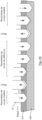
- the tip of a drill 13 conventionally comprises a central edge 130 extended laterally by main edges 131 which end in cutting tips 132.
- the cutting tips 132 are extended by lists 133 which extend helically and define the diameter of the drill bit.
- the function of the drill is to cut the material following a trajectory defined by the cutting parameters (in particular rotation speed, feed per revolution with possibly an alternating component).
- Measuring and monitoring the load on the drill bit (torque or thrust force along the drilling axis) during a drilling operation can contribute to controlling the quality of drilling and managing wear. of the drill.
- Such a technique is based, when the drill bit pierces a given material with given cutting parameters specific to this material (these parameters are called “material cutting parameters”), on a comparison of the load values to which the drill bit is subjected with intervals predetermined load values specific to this material drilled by a given type of drill and its cutting parameters.
- cutting parameters of reference are predetermined in the laboratory for each material drilled with the reference cutting parameters and a drill bit similar to that used.
- the new material identified is the one whose load value interval contains the load value measured during drilling with the reference parameters.
- the reference cutting parameters are, for a given group of materials, the binding cutting parameters based on the cutting speed and feed values of the material(s) of the group imposing minimum or maximum limit values, below or, above which a major inconvenience appears, such as premature wear of the cutting edges of the drill.
- monitoring the load on the drill both in order to evaluate the wear of the drill and to identify the material being drilled, can be made difficult by the existence of parasitic phenomena having an impact on the load of the drill.
- a rear taper or unpinning is generally provided on the lists, such that the shank diameter of the drill is smaller than the diameter of the tips at a rate of 10 ⁇ m on the diameter per 10mm of drill length.
- the unpinning must not be too great so as not to degrade the centering of the drill in the hole and thus risk the drilling moving out of alignment with the desired trajectory.
- Another parasitic phenomenon is linked to the evacuation of chips or during a drilling operation.
- Evacuation is also obtained by injecting oiled compressed air into two channels present in the body of the drill.
- the compressed air comes out of the channels at the end of the drill on the clearance faces of the drill, it comes out of the hole being drilled going up through the two flutes in the case of helical or symmetrical drills or the flute in the case of three drills. -quarters.
- the invention aims in particular to provide an effective solution to at least some of these different problems.
- an objective of the invention is to optimize the performance of drilling operations, in particular to improve the quality of drilling and/or to better generate the use of cutting tools. .
- the invention aims, according to at least one embodiment, to make the identification of a material being drilled more reliable.
- Another objective of the invention is, according to at least one embodiment, to make the detection of wear of a drill more reliable.
- Another objective of the invention is, according to at least one embodiment, to make it possible to detect the existence of a chip jam during a drilling operation.
- Another objective of the invention is, according to at least one embodiment, to make it possible to evaluate the level of direct friction or by poor evacuation of chips from the strips of a drill against the walls of an element being drilled. .
- Another objective of the invention is, according to at least one embodiment, to provide such a technique which is simple and/or reliable.
- the invention proposes a drilling method according to claim 1.
- the invention is based on an original approach which consists of determining, during a drilling operation, the overall drag due to the internal friction of a drilling device and to the friction of the lists against the walls of the drilled element. .
- stopping the drilling operation in progress means that the advance of the drill in the direction of drilling of the element to be drilled is stopped, the rotational movement of the drill may or may not be maintained at this stage.
- the recoil of the drill over a predetermined distance is necessarily a partial retreat of the drill so that its cutting edges are no longer engaged with the element to be drilled (we no longer carry out at this stage a removal of material) while its lists are no longer in contact with the element to be drilled.
- the portion of the strips located inside the hole being drilled will vary depending on the depth of the drilling being done. The recoil therefore does not induce total extraction outside the hole being drilled by the cutting tool.
- Such a parameter can be used, during a drilling operation, to detect the occurrence of an event whose consideration can make it possible to optimize the drilling.
- the reaching of a predetermined high threshold by the overall drag could mean that the drill and/or the drilling device is worn, or more generally an anomaly.
- the drilling operation can then be stopped and/or an alert message issued so that measures can be taken to correct the problem(s) that have arisen in order to improve the quality of the drilling.
- Such a parameter can be used, during a drilling operation, to detect the occurrence of an event whose consideration can make it possible to optimize drilling, in particular poor evacuation of chips (jamming) or tightening of the material on the drill bit.
- Such a parameter can be used, during a drilling operation, to detect the occurrence of an event whose consideration can make it possible to optimize drilling, in particular wear of the cutting edges or adhering material.
- said predetermined cutting parameters are reference cutting parameters specific to the group of materials to which the material being drilled belongs and to the type of drill used to carry out the drilling operation in progress, said method further comprising a step of comparing said at least one load value representative of the cutting forces with predetermined intervals of reference load value representative of the cutting forces, each of said intervals being specific to one of the materials of said group.
- a method according to the invention may further comprise a step of stopping the drilling operation in progress and/or emitting an alert signal when said at least one load value representative of the cutting forces does not belong to any of said reference load value intervals representative of the cutting forces.
- a method according to the invention preferably comprises a clearing step when it is detected that the friction of the strips is abnormal.
- said predetermined cutting parameters are predetermined material cutting parameters specific to the material being drilled and to the type of drill used to carry out the drilling operation in progress, a method according to the invention comprising a step for checking the cutting forces comprising the comparison of said at least one load value representative of the cutting forces to a standard interval of predetermined material cutting load values specific to the material being drilled for a drill whose cutting edges present the minimum quality required for correct drilling and for said predetermined material cutting parameters.
- Said step of checking the cutting forces preferably comprises the detection of anomalous cutting forces when said at least one load value representative of the cutting forces is not included in said standard interval of material cutting load values.
- a method according to the invention comprises a step of stopping said drilling when it is detected that the cutting forces are abnormal or that no material is identified.
- a method according to the invention comprises a step of emitting an alert signal when it is detected that the friction of the strips is abnormal and/or when it is detected that the cutting forces are abnormal and /or no material is identified.
- the present invention also relates to a drilling device according to claim 11.
- a device comprises means for comparing said at least one load value representative of the cutting forces with predetermined intervals of reference load value representative of the cutting forces, each of said intervals being specific to one of the materials of said group.
- a device comprises means for stopping the drilling operation in progress and/or emitting an alert signal when said at least one load value representative of the cutting forces n 'belongs to none of said reference load value intervals representative of the cutting forces.
- a device comprises means for controlling unblocking when it is detected that the friction of the strips is abnormal.
- said predetermined cutting parameters are predetermined material cutting parameters specific to the material being drilled and to the type of drill used to carry out the drilling operation in progress, a device according to the invention further comprising means for verifying the cutting forces comprising means for comparing said at least one load value representative of the cutting forces to a standard interval of predetermined material cutting load values specific to the material being drilled for a drill whose the cutting edges have the minimum quality required for correct drilling and for said parameters of predetermined material cutting.
- a device comprises means for detecting anomalous cutting forces when said at least one load value representative of the cutting forces is not included in said standard interval of material cutting load values.
- a device comprises means for stopping said drilling operation when it is detected that the cutting forces are abnormal or that no material is identified.
- a device comprises means for emitting an alert signal when it is detected that the friction of the strips is abnormal and/or when it is detected that the cutting forces are abnormal and/or no material is identified.
- Tables 1 to 9 illustrate tables of data taken into consideration during the implementation of an example of a method according to the invention.
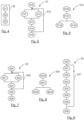
- the appendix illustrates a flowchart of an example drilling process according to the invention.
- a drilling device or drill for implementing a method according to the invention comprises a drill or a drilling robot with controlled cutting parameters.
- a drilling device is known per se to those skilled in the art and is not described in detail here apart from the elements more specific to the invention.
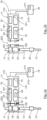
- such a drilling device 10 comprises a casing 11.
- the casing 11 comprises a first casing portion 110 and a second casing portion 111 which extend substantially perpendicular to each other.
- the casing could extend along a single axis and thus not have an essentially T shape.
- the drill includes an output shaft 12, or spindle, movable in rotation and in translation along the same axis.
- This output shaft 12 is connected by means of one or more transmission chains to motor means.
- Rotation training and advance training are done along the same axis. Such a principle is described in particular in the document FR3000693 .
- the drilling device comprises a removable drill head 301. This corresponds to the second portion of the casing 111. Reversible mechanical and electrical connection means 303 will conventionally be implemented between the removable drill head 301 and the first portion of the casing. housing 110 (i.e. the body of the drill).
- This head includes a memory 135 such as for example an RFID chip or any other suitable data storage means.
- the first portion of casing 110 will therefore include a reader 25 capable of reading the information contained in the memory associated with the drill head 301.
- the load on the drill bit in the air of a drilling device results primarily from friction that takes place within the removable drill head and the rest of the housing.
- the head comprises means 20 for securing a cutting tool 13, for example a drill bit, placed at the end of the output shaft 12.
- a cutting tool 13 for example a drill bit
- These means of securing may for example include a drill clamp. Obviously, these securing means can make it possible to secure a plurality of different drills to the drill.
- information relating to the drill is carried by the memory integrated into the head.
- the memory is integrated directly into the drill bit.
- the memory is associated with the drill whether it is integrated into its tool holder or directly in the drill.
- An alternative to an RFID tag could be an electronic memory connected to the drill controller by electrical connectors.
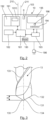
- the drill is connected to a controller 19 by a cable which conventionally includes power supply wires 210 of the motors and possibly communication wires 211. It could possibly also include tubes for passing fluid(s) such as lubricant.
- the drill also includes a transmit/receive module (not shown) to communicate with the controller.
- the controller also includes an input-output interface 193, a user interface for managing a command input means 194 (keyboard, touch screen, mouse, etc.), a display means 195 (screen, display, indicator light) and possibly, a means of emitting a sound signal on an audible frequency 196.
- a command input means 194 keyboard, touch screen, mouse, etc.
- a display means 195 screen, display, indicator light
- a means of emitting a sound signal on an audible frequency 196 possibly, a means of emitting a sound signal on an audible frequency 196.
- the input-output interface can allow programming of drilling strategies.
- the drill itself can integrate a man-machine interface 24 allowing the start of drilling and the visualization of information relating to the progress of the drilling.
- This controller 19 comprises two power supplies 191, 192 making it possible to power the rotation drive motor 14 of the drill and the feed motor 16.
- These power supplies can for example be inverters suitable for powering synchronous motors with permanent magnets.
- These motors are provided with an angle sensor 141, 161 whose signal, representative of the angle of the rotor relative to the stator, is used by the inverters to correctly power the synchronous motors.
- the controller 19 includes a connector 196 for connecting to an electric current supply source.
- the controller is separated from the drill. In a variant, it could be integrated there, that is to say be housed inside the drill casing.
- the code instructions of the computer program are, for example, loaded into memory RAM 180 before being executed by the processor of the processing unit 181.
- RAM 180 contains in particular the appropriate formulas for calculating the different quantities determined during the implementation of the method.
- the processor of the processing unit 181 carries out the various necessary calculations. It can then, for example, display the result, record it, transmit it to a network, compare it to one or more predetermined threshold values and, if necessary, control the screwdriving device accordingly, emit a visual and/or audible alarm in if necessary...
- FIG 2 illustrates only one particular way, among several possible, of producing a controller, so that it carries out the steps of the drilling process according to the invention (in any of the different embodiments, or in a combination of these modes of implementation). realization). Indeed, these steps can be carried out indifferently on a reprogrammable calculation machine (a PC computer, a DSP processor or a microcontroller) executing a program comprising a sequence of instructions, or on a dedicated calculation machine (for example a set of logic gates like an FPGA or an ASIC, or any other hardware module).
- a reprogrammable calculation machine a PC computer, a DSP processor or a microcontroller
- a program comprising a sequence of instructions
- a dedicated calculation machine for example a set of logic gates like an FPGA or an ASIC, or any other hardware module.
- the corresponding program (that is to say the sequence of instructions) can be stored in a removable storage medium (such as for example a floppy disk, a CD-ROM or DVD-ROM) or not, this storage medium being partially or totally readable by a computer or processor.
- a removable storage medium such as for example a floppy disk, a CD-ROM or DVD-ROM
- the device comprises means for measuring at least one piece of information representative of the load on the drill bit during drilling.
- controller 19 are connected to controller 19 to process the signals.
- the device comprises means for activating predetermined reference cutting parameters specific to the group of materials to which the material being drilled belongs and to the type of drill used to carry out the drilling operation in progress, and means for comparison of said at least one load value representative of the cutting forces with predetermined intervals of reference load value representative of the cutting forces, each of said intervals being specific to one of the materials of said group.
- the device comprises means for stopping the drilling operation in progress and/or emitting an alert signal when said at least one load value representative of the cutting forces does not belong to any of said intervals. reference load value representative of the cutting forces.
- the controller is programmed to activate a jam release when it is detected that the friction of the strips is abnormal.
- Unblocking consists, during a drilling operation, of moving the drill backward while maintaining its rotation, then of driving it again in the direction of drilling. This is to evacuate the chips from the hole being drilled.
- the drilling device comprises means for verifying the cutting forces comprising means for comparing said at least one load value representative of the cutting forces to a standard interval of predetermined material cutting load values specific to the material being processed. drilling for a drill whose cutting edges have the minimum quality required for correct drilling and for said predetermined material cutting parameters.
- the drilling device comprises means for detecting anomalous cutting forces when said at least one load value representative of the cutting forces is not included in said standard interval of material cutting load values.
- the controller is programmed to stop the drilling operation when it is detected that the cutting forces are abnormal or that no material is identified.
- the controller is programmed to generate the emission of an alert signal when it is detected that the friction of the strips is abnormal and/or when it is detected that the cutting forces are abnormal and/or that no material is not identified.
- the different means of measurement and determination include in particular the controller and the necessary sensors.
- a drill bit is associated during its life with a removable drill head, this head carrying a memory containing information relating to the drill bit.
- the drilling system then includes a drill with a detachable head and a removable drill head.
- the drilling system may include a drill with an integrated head equipped with a memory.
- the drill bit is associated with the memory of the drilling system.
- a device according to the invention can also be implemented to carry out the drilling of elements composed of stacks of successive layers of different materials, each stack constituting a group of materials.
- drill bits can be used in production, with several types of drilling devices and several different materials forming one or more material groups can be drilled in production.
- drilling equipment drilling systems (drill with detachable or integrated head, where applicable removable drill head) and cutting tools) then preparation of drilling equipment before sending into production is implemented.
- the preliminary evaluation is carried out in laboratory conditions, that is to say outside of production. Its objective is to determine standard values or standard value intervals specific to the types of drilling equipment likely to be used in production.
- the data collected during this laboratory evaluation is then used, by the tooling department of a production unit, during the preparation of drilling equipment before sending it into production.
- the tools department which typically manages the drilling equipment fleet within the production unit, then records in the drilling equipment memories the values and standard value intervals necessary for carrying out drilling operations.
- the preliminary laboratory evaluation relates on the one hand to each type of drilling machine with a removable head and on the other hand to the torque formed by a type of drill associated with a removable head type.
- a type of drill is characterized in particular by its shape, its material, its coating, its diameter, etc.
- a type of removable drill head is characterized in particular by its transmission, its dimensions, its performance, etc.
- a type of drill with a removable or integrated head is characterized in particular by its transmission, its dimensions, its performance, etc.
- the preliminary laboratory evaluation concerns the drill equipped with a drill bit.
- the drills used are in a “run-in” state, that is to say having reached a level of use corresponding to approximately 10% of their lifespan.
- the materials are the same as those used in the construction of the structures which will have to be drilled in production.
- a preliminary step of laboratory evaluation of at least one load value representative of the drag of the drilling system due to internal friction therein (transmission and motor) is implemented for each type of drilling system.
- the drilling system can be of the detachable head type: it then comprises a drill and a removable drill head.
- the drilling system can be of the integrated head type: the drill and its head form a single unit.
- the drill with a detachable head i.e. the body of the drill
- the drill with a detachable head will preferably be tested alone so as to determine at least one piece of information representative of the drag of the drill without a removable head.
- the removable drill heads will be tested on a drill without a removable head already tested, so as to determine at least one piece of information representative of the drag of the removable head.
- the at least one load value representative of the drag of the drill will then be equal to the sum of the at least one load value representative of the drag. drill without removable head and at least one load value representative of the removable head.
- the at least one load value representative of the drag may not be taken into account if it is negligible, that is to say less than 5% of the at least one load value measured. during drilling in full material.
- At least one load value is measured without load on the drill, neither axial nor torque, for a given output spindle length, and is recorded as a load value representative of the drag of the drilling device.
- the measurement of at least one load value is carried out by rotating the drill without load while applying the reference cutting parameters corresponding to the type of drill and the group of materials considered.
- the drag of the drilling device may vary depending on the output length of the drill spindle.
- Strategy 3 is identical to strategy 2 but with a calibrated load applied to the drill (torque and axial force) representative of an average drag of the drill strips on the walls of a hole.
- the recording of at least one load value representative of the drag of the drill is no longer measured by rotating the drill empty but by rotating it by subjecting the spindle to a calibrated load whose value is preferably of the order of that of the drag load of the drill.
- This variant makes it possible to guarantee that the measurement of at least one load value representative of the drag of the drill is carried out while the internal components of the drill supposed to be in contact when operating normally are actually in contact (for example the pinions of the drill). transmission).
- Other parameters can influence the drag of the drilling system such as the temperature of the drill or the number of drilling cycles performed by the drilling system.
- Strategy 4 is identical to strategy 3 but with coefficients weighting the influence of the temperature of the drilling system and/or its wear as a function of the number of drilling cycles carried out.
- the at least one load value representative of the drag of the drilling system could be measured at the start of drilling during the approach phase of the drill in the approach air. This alternative will be described later in the paragraph dedicated to the application of the process in production.
- a preliminary step 51 of laboratory evaluation of reference load values representative of the cutting forces is carried out for each type of drill and each of the materials for each of the given groups of materials which may be required to be drilled, including the air.
- Air is considered a material to be drilled to the extent that before entering an element to be drilled, the drill is located in the ambient air called approach air. After leaving the element to be drilled, the drill is located in the ambient air called exit air.
- the tables resulting from the laboratory evaluation are made available to the company's tooling department, in the form of digital files, to enable it to prepare the drilling equipment before putting it into production.
- the tooling department is responsible for storing and preparing drilling equipment (drilling system and cutting tool) for their use in production.
- this tooling department receives a new drilling system component (drill with integrated head, drill body with detachable head, detachable drill head), the operator loads it into the memory of the drill body or into the detachable head or in the drill, the different applications envisaged where this component is likely to be used, as well as, for each of these applications, the corresponding digital files (or tables of values).
- a new drilling system component drill with integrated head, drill body with detachable head, detachable drill head
- the operator loads it into the memory of the drill body or into the detachable head or in the drill, the different applications envisaged where this component is likely to be used, as well as, for each of these applications, the corresponding digital files (or tables of values).
- the memory of a drill body will therefore receive tables of the type in table 5 of the different applications where this body is likely to be used, as well as a table of the type in table 8 listing the different applications where this body is likely to be used. be used and for each of these applications the corresponding table 5.
- Table 8 Table 8 ⁇ /b> Drill body memory Application Table 15 1 2 3 4 5
- the memory of a detachable head will therefore receive tables of the type of tables 2, 3 and 4 of the different applications where this head is likely to be used, as well as a table of the type of table 7 listing the different applications where this head detachable is likely to be used and for each of these applications the corresponding tables 2, 3 and 4.
- Table 7 Table 7 ⁇ /b> Detachable head memory
- the memory of an integrated head drill will therefore receive tables of the type in tables 2, 3 and 6 of the different applications where this drill is likely to be used, as well as a table of the type in table 9 listing the different applications where this drill with integrated head can be used and for each of these applications the tables of the type of tables 2, 3 and 6 corresponding.
- Table 9 Table 9 ⁇ /b> Integrated head drill memory
- Table 12 Table 13 Table 16 1 2 3 4 5
- these parameters can be stored in the drill's memory.
- these parameters can be stored on a company server to which the drill has access via radio communication.
- the operator of the tooling department updates the memories of the components of the drilling systems.
- the tooling department operator When the tooling department operator receives a preparation request for a given application, he takes from his store the drill body, the drill head (or the drill with integrated head) and the drill bit necessary for the application, assembles these components and makes the drilling system thus constituted available to the production department.
- the production department obtains from the tooling department the drilling system adapted to its application.
- the production operator selects, using the drilling system's human machine interface, the application concerned.
- the controller of the drilling system will then search in the memories of the drill body with detachable head and the detachable drill head (or the drill with integrated head) the values of tables 2, 3, 4, 5, 6 corresponding to this application.
- the drilling operation is then carried out according to the selected application pre-programmed in the controller 19.
- a measurement is carried out, preferably continuously (in time real), of at least one gross load value on the drill bit.
- This may consist of measuring one or more parameters among the torque transmitted to the drill via the sensor 22, the axial thrust transmitted to the drill via the sensor 23, the power or the electric current consumed by at least one of the motors of rotation or translation drive via sensor 1910.
- a raw load value is therefore that delivered by a sensor which is then used to determine physical quantities used within the framework of drilling regulation.
- the at least one gross load value measured after stabilization is in reality essentially representative of the internal friction of the drilling system. drilling since the friction of the strips in the approach air is negligible.
- the drill 13 is driven towards the part to be drilled during an approach phase 71.
- the drill is driven with the reference cutting parameters.
- the at least one gross load value measured in real time, before the cutting edges enter the part to be drilled, is representative of the drag of the drilling system. This value is stored in the system memory (step 712).
- the implementation of these steps 711 and 712 therefore makes it possible to avoid the laboratory determination of at least one load value representative of the drag of the drilling system according to one of the strategies 1 to 4 described previously in the dedicated paragraph. to the preliminary evaluation in the laboratory, and its recording by the tooling department in the memory of the drilling system.
- the drill is driven according to the cutting parameters of the approach air predetermined and recorded in its memory.
- These cutting parameters can for example include a rotation frequency, a feed speed, etc. (see table 3).
- Measuring at least one gross load value while the drill bit is moving through the approach air, with the cutting parameters of the approach air, before its cutting edges enter the workpiece. drilling constitutes a step of measuring at least one load value representative of the drag of the drilling system operating with the cutting parameters of the approach air. This value is stored in the system memory (step 714).
- the method includes a step 72 of detecting the entry of the drill 13 into the element to be drilled.
- the drilling process continues until it is detected that the drill bit has entered the workpiece.
- the sequence of sub-steps of step 72 constitutes a verification loop repeated at a frequency of several kilohertz corresponding to the calculation frequency of the controller.
- a step verification of a real change of material is implemented during which the reference cutting parameters corresponding to the type of drill used and the group of materials being drilled are activated.
- the determination 731 of at least one load value representative of the drag of the drilling system consists of taking into account the values measured and recorded in the optional step 712 of the method or measured in the laboratory according to one of strategies 1 to 4 described previously then recorded by the tooling department before putting into production corresponding to the drill and/or head used.
- weighting factors such as the temperature of the drill and/or the number of cycles thereof, then these parameters are measured in a manner known per se to those skilled in the art and the corresponding curves are used. to determine at least one load value representative of the drag of the drilling system.
- the determination 732 of at least one load value representative of the drag of the strips comprises the subtraction, from the at least one load value representative of the overall drag measured in step 7303, of the at least one value of load representative of the drag of the drilling system.
- a step 733 of comparing at least one load value representative of the drag of the strips becomes greater than the maximum standard load value representative of the drag of the strips with the maximum standard load value representative of the drag of the strips corresponding to the group materials and type of drill considered is implemented.
- the clearing step 74 is followed by a new step 73 of checking the friction of the lists.
- step 75 drilling is stopped (step 75), the drill is retracted (step 76) and an alert is sent to the operator is sent (step 77) to indicate the occurrence of an anomaly.
- step 735 If the friction of the strips is considered normal (step 735), the drilling process continues.
- a step 78 of determining the material being drilled is implemented.
- An activation 780 of the predetermined reference parameters recorded in the memory associated with the drill and corresponding to the group of materials concerned is implemented, or these parameters are maintained if they have not been stopped momentarily.
- At least one piece of information representative of the raw load on the drill is measured after a phase of stabilization thereof and complete engagement of the cutting edges (or cutting tips) in the new material (step 781).
- the measurement phase can take place over a drill stroke of between 0.5 and 1 millimeter.
- At least one load value representative of the cutting forces is calculated (step 782). This is equal to the subtraction, from the at least one gross load value on the drill measured in step 781, from the at least one load value representative of the overall drag previously determined in step 730. .
- the at least one load value representative of the cutting forces is compared by the controller to the standard intervals of reference load values representative of the cutting forces recorded in the drill memory for each of the materials in the group (step 783).
- the material being drilled is that whose reference load value interval representative of the cutting forces contains at least one calculated load value representative of the cutting forces (step 784).
- step 785 If the at least one load value representative of the calculated cutting forces does not belong to any standard interval of reference load value representative of the cutting forces of the different known materials (step 785), the drilling in progress does not correspond to the drilling of a known material which is the meaning of a potential anomaly. Drilling is then stopped (step 75), the drill retracted (step 76) and an alert sent (step 77) to the operator to inform him that the cutting edges of the drill are potentially damaged.
- step 784 In the case where a known material is identified (step 784), and the identified material is not the outlet air, a step 79 of checking the cutting forces of the identified material is then implemented.
- Step 79 of checking the cutting forces includes a step 790 of measuring at least one value of load representative of the overall drag due to friction of the drilling device and friction of the strips.
- the at least one load value representative of the cutting forces is compared by the controller to the standard interval of load values representative of the cutting forces recorded in the memory of the drill corresponding to the material identified during drilling (step 794 ).
- step 795 If the at least one load value representative of the calculated cutting forces does not belong to the interval of load value representative of the cutting forces of the identified material (step 795), a potential anomaly exists. Drilling is then stopped (step 75), the drill retracted (step 76) and an alert sent (step 77) to the operator to notify him of an anomaly such as the fact that the cutting edges of the drill are potentially damaged or the presence of adhering material or other defect.
- step 796 If the load value representative of the cutting forces is within the standard interval of load value of the cutting forces of the identified material (step 796), no anomaly is detected and drilling continues until 'until entry into another material is detected (step 80).
- This step 80 of detecting the entry of the drill into a new material during drilling is also called the material change detection step.
- step 803 If no material change is detected (step 803), the drilling process continues until a material change is detected.
- step 802 new steps 73 of checking the friction of the lists then 78 of determining the material being drilled.
- step 78 of determining the material being drilled the material being drilled identified is the outlet air
- drilling continues over a predetermined stroke, for example of 3 millimeters (step 81).
- a predetermined stroke for example of 3 millimeters
- the drill is reassembled (step 82) and a drilled hole alert is sent to the operator (step 83).
- the friction of the strips can be taken into consideration, for example, to detect poor chip evacuation (jamming) or material tightening on the drill,
- Cutting forces can be taken into consideration, for example, to detect wear on the cutting edges of a drill bit, an adhering material.
- thresholds will be predetermined in the laboratory for each material and each type of drill, upon reaching which poor evacuation of the chip, tightening of the material, wear of the drill, and adhering material are detected.
Landscapes
- Engineering & Computer Science (AREA)
- Mechanical Engineering (AREA)
- Human Computer Interaction (AREA)
- Manufacturing & Machinery (AREA)
- Physics & Mathematics (AREA)
- General Physics & Mathematics (AREA)
- Automation & Control Theory (AREA)
- Drilling And Boring (AREA)
- Numerical Control (AREA)
Claims (20)
- Verfahren zum Bohren eines zu bohrenden Elements, das einen Stapel aus einer Folge von Schichten unterschiedlicher Materialien umfasst, mittels einer Bohrvorrichtung (10) und eines Schneidwerkzeugs (13), welches Fasen (133) und Schneidkanten (131) aufweist, wobei das Verfahren die folgenden Schritte umfasst:- Bestimmen mindestens eines Lastwerts, der für den Gesamtwiderstand aufgrund der inneren Reibung der Bohrvorrichtung und der Reibung der Fasen in dem zu bohrenden Element repräsentativ ist, wobei der Schritt des Bestimmens mindestens eines für den Gesamtwiderstand repräsentativen Lastwerts die folgenden Unterschritte umfasst:- Anhalten des laufenden Bohrvorgangs,- teilweises Zurückziehen des Schneidwerkzeugs über einen vorbestimmten Abstand, wobei der vorbestimmte Abstand derart gewählt wird, dass die Schneidkanten nicht mehr mit dem zu bohrenden Element in Kontakt stehen, während sich die Fasen noch innerhalb des gerade gebohrten Lochs in dem zu bohrenden Element befinden,- Antreiben des Schneidwerkzeugs mit vorbestimmten Schneidparametern,- Messen mindestens eines Lastwerts während des Antreibens des Schneidwerkzeugs mit den Schneidparametern, bevor seine Schneidkanten wieder mit dem zu bohrenden Element in Kontakt kommen, wobei der mindestens eine so gemessene Lastwert nach Stabilisierung der Lastwerte derjenige ist, der für den Gesamtwiderstand aufgrund der inneren Reibung der Bohrvorrichtung und der Reibung der Fasen in dem zu bohrenden Element repräsentativ ist;- Erfassen, anhand des mindestens eines Lastwerts umfasst, der für den Gesamtwiderstand repräsentativ ist, des Auftretens eines Ereignisses, dessen Berücksichtigung eine Optimierung des Bohrvorgangs ermöglichen kann.
- Verfahren nach Anspruch 1, umfassend einen Schritt des Bestimmens mindestens eines für den Widerstand der Fasen aufgrund der Reibung der Fasen in dem zu bohrenden Element repräsentativen Lastwerts, wobei dieser Schritt die folgenden Unterschritte umfasst:- das Bestimmen mindestens eines für den Widerstand der Bohrvorrichtung aufgrund der inneren Reibung derjenigen Bohrvorrichtung, die mit den vorbestimmten Schneidparametern arbeitet, repräsentativen Lastwerts,- die Subtraktion des mindestens einen für den Widerstand der Bohrvorrichtung repräsentativen Lastwerts von dem mindestens einen Lastwert, der für den Gesamtwiderstand repräsentativ ist, wobei das Ergebnis der Subtraktion gleich dem mindestens einen Lastwert ist, der für den Widerstand der Fasen repräsentativ ist.
- Verfahren nach Anspruch 1 oder 2, umfassend einen Schritt des Bestimmens mindestens eines für diejenigen Schnittkräfte repräsentativen Lastwerts, die durch das Entfernen von Material von dem zu bohrenden Element während eines Bohrvorgangs erzeugt werden, der die folgenden Unterschritte umfasst:- Messen mindestens eines Lastwerts während des Bohrens des zu bohrenden Elements mit den vorbestimmten Schneidparametern,- Subtraktion des mindestens einen für den Gesamtwiderstand repräsentativen Lastwerts von dem mindestens einen Lastwert, der während des Bohrens des zu bohrenden Elements gemessen wird, wobei das Ergebnis der Subtraktion gleich dem mindestens einen Lastwert ist, der für die Schnittkräfte repräsentativ ist.
- Verfahren nach Anspruch 3, wobei die vorbestimmten Schneidparameter Referenzschneidparameter sind, die für die Gruppe von Materialien, zu der das Material gehört, das gerade gebohrt wird, und die Art desjenigen Bohrers spezifisch sind, der eingesetzt wird, um den laufenden Bohrvorgang durchzuführen, wobei das Verfahren einen Schritt des Vergleichens des mindestens einen für die Schnittkräfte repräsentativen Lastwerts mit vorbestimmten, für die Schnittkräfte repräsentativen Bereichen des Referenzlastwerts aufweist, wobei jeder der Bereiche für eines der Materialien der Gruppe spezifisch ist.
- Verfahren nach Anspruch 4, umfassend einen Schritt des Anhaltens des laufenden Bohrvorgangs und/oder des Sendens eines Warnsignals, wenn der mindestens eine Lastwert, der für die Schnittkräfte repräsentativ ist, zu keinem der für die Schnittkräfte repräsentativen Bereiche des Referenzlastwerts gehört.
- Verfahren nach Anspruch 2, umfassend einen Schritt des Überprüfens der Reibung der Fasen, umfassend:- das Vergleichen des mindestens einen Lastwerts, der für den Widerstand der Fasen repräsentativ ist, mit einem vorbestimmten Schwellenwert,- das Feststellen einer anomalen Reibung der Fasen, wenn der mindestens eine Lastwert, der für den Widerstand der Fasen repräsentativ ist, höher als der vorbestimmte Schwellenwert wird.
- Verfahren nach Anspruch 6, umfassend einen Schritt des Entkernens, wenn festgestellt wird, dass die Reibung der Fasen anomal ist.
- Verfahren nach Anspruch 3, wobei die vorbestimmten Schneidparameter vorbestimmte Materialschneidparameter sind, die für das gerade gebohrte Material und die Art desjenigen Bohrers spezifisch sind, der eingesetzt wird, um den laufenden Bohrvorgang durchzuführen, wobei das Verfahren einen Schritt des Überprüfens der Schnittkräfte umfassend das Vergleichen des mindestens einen für die Schnittkräfte repräsentativen Lastwerts mit einem vorbestimmten kalibrierten Bereich von Materialschneid-Lastwerten umfasst, der für das gerade gebohrte Material, für einen Bohrer, dessen Schneidkanten die erforderliche Mindestqualität für ein korrektes Bohren aufweisen, und für die vorbestimmten Materialschneidparameter spezifisch ist.
- Verfahren nach Anspruch 8, wobei der Schritt des Überprüfens der Schnittkräfte das Erfassen von anomalen Schnittkräften aufweist, wenn der mindestens eine Lastwert, der für die Schnittkräfte repräsentativ ist, nicht in dem kalibrierten Bereich von Materialschneid-Lastwerten enthalten ist.
- Verfahren nach Anspruch 3, 4 und 8, umfassend einen Schritt des Identifizierens des Materials, das gerade gebohrt wird, wobei der Schritt des Identifizierens umfasst:- einen Schritt des Aktivierens oder des Aufrechterhaltens der Referenzschneidparameter, die für die Gruppe von Materialien, zu der das Material gehört, das gerade gebohrt wird, und die Art des Bohrers spezifisch sind, der eingesetzt wird, um den laufenden Bohrvorgang durchzuführen;- einen Schritt des Bestimmens des Materials, das gerade gebohrt wird, wobei das Material, das gerade gebohrt wird, jenes ist, dessen Bereich des für die Schnittkräfte repräsentativen Referenzlastwerts den mindestens einen Lastwert enthält, der für die Schnittkräfte repräsentativ ist;- einen Schritt des Aktivierens von vorbestimmten Materialschneidparametern, die für das in dem Schritt des Bestimmens identifizierte Material und die Art des eingesetzten Bohrers spezifisch sind,- einen Schritt des Bestimmens mindestens eines Lastwerts, der für die Schnittkräfte mit den Materialschneidparametern repräsentativ ist,- einen Schritt des Validierens des bei dem Schritt des Bestimmens identifizierten Materials, wobei das Bestimmen des Materials validiert wird, wenn der mindestens eine für die Schnittkräfte repräsentative Lastwert, der bestimmt wird, indem die Materialschneidparameter umgesetzt werden, zu einem Bereich von vorbestimmen Lastwerten gehört, die für die Schnittkräfte mit den Materialschneidparametern für das identifizierte Material repräsentativ sind.
- Bohrvorrichtung (10), die dazu bestimmt ist, zum Durchführen mindestens eines Bohrvorgangs eines zu bohrenden Elements, das einen Stapel aus einer Folge von Schichten unterschiedlicher Materialien umfasst, mittels eines Schneidwerkzeugs (13) eingesetzt zu werden, welches Fasen (133) und Schneidkanten (131) aufweist, wobei die Vorrichtung Mittel zum Bestimmen mindestens eines für den Gesamtwiderstand aufgrund der inneren Reibung der Bohrvorrichtung und der Reibung der Fasen in dem zu bohrenden Element repräsentativen Lastwerts aufweist, wobei die Mittel zum Bestimmen mindestens eines für den Gesamtwiderstand repräsentativen Lastwerts aufweisen:- eine Steuereinheit (19), die dazu eingerichtet ist, die Schritte eines Verfahrens zum Bohren nach einem der Ansprüche 1 bis 10 durchzuführen,- Mittel zum Anhalten des laufenden Bohrvorgangs,- Mittel zum teilweisen Zurückziehen des Schneidwerkzeugs über einen vorbestimmten Abstand, wobei der vorbestimmte Abstand derart gewählt ist, dass die Schneidkanten nicht mehr mit dem zu bohrenden Element in Kontakt stehen, während sich die Fasen noch innerhalb des gerade gebohrten Lochs in dem zu bohrenden Element befinden,- Mittel zum Antreiben des Schneidwerkzeugs mit vorbestimmten Schneidparametern,- Mittel zum Messen mindestens eines Lastwerts während des Antreibens des Schneidwerkzeugs mit den Schneidparametern, bevor seine Schneidkanten wieder mit dem zu bohrenden Element in Kontakt kommen, und wobei nach Stabilisierung der Lastwerteder mindestens eine so gemessene Lastwert derjenige mindestens eine Lastwert ist, der für den Gesamtwiderstand aufgrund der inneren Reibung der Bohrvorrichtung und der Reibung der Fasen in dem zu bohrenden Element repräsentativ ist.
- Vorrichtung nach Anspruch 11, umfassend Mittel zum Bestimmen mindestens eines für den Widerstand der Fasen aufgrund der Reibung der Fasen in dem zu bohrenden Element repräsentativen Lastwerts, wobei diese Mittel aufweisen:- Mittel zum Bestimmen mindestens eines für den Widerstand der Bohrvorrichtung aufgrund der inneren Reibung der Bohrvorrichtung, die mit den vorbestimmten Schneidparametern arbeitet, repräsentativen Lastwerts,- Mittel zur Subtraktion des mindestens einen für den Widerstand der Bohrvorrichtung repräsentativen Lastwerts von dem mindestens einen für den Gesamtwiderstand repräsentativen Lastwert, wobei das Ergebnis der Subtraktion gleich dem mindestens einen Lastwert ist, der für den Widerstand der Fasen repräsentativ ist.
- Vorrichtung nach Anspruch 11 oder 12, umfassend Mittel zum Bestimmen mindestens eines für diejenigen Schnittkräfte repräsentativen Lastwerts, die durch das Entfernen von Material von dem zu bohrenden Element während eines Bohrvorgangs erzeugt werden, wobei diese Mittel aufweisen:- Mittel zum Messen mindestens eines Lastwerts während des Bohrens des zu bohrenden Elements mit den vorbestimmten Schneidparametern,- Mittel zur Subtraktion des mindestens einen für den Gesamtwiderstand repräsentativen Lastwerts von dem mindestens einen Lastwert, der während des Bohrens des zu bohrenden Elements gemessen wird, wobei das Ergebnis der Subtraktion gleich dem mindestens einen Lastwert ist, der für die Schnittkräfte repräsentativ ist.
- Vorrichtung nach Anspruch 13, wobei die vorbestimmten Schneidparameter Referenzschneidparameter sind, die für die Gruppe von Materialien, zu der das Material gehört, das gerade gebohrt wird, und die Art des Bohrers spezifisch sind, der eingesetzt wird, um den laufenden Bohrvorgang durchzuführen, wobei die Vorrichtung Mittel zum Vergleichen des mindestens einen für die Schnittkräfte repräsentativen Lastwerts mit vorbestimmten für die Schnittkräfte repräsentativen Bereichen des Referenzlastwerts aufweist, wobei jeder der Bereiche für eines der Materialien der Gruppe spezifisch ist.
- Vorrichtung nach Anspruch 14, umfassend Mittel zum Anhalten des laufenden Bohrvorgangs und/oder des Sendens eines Warnsignals, wenn der mindestens eine Lastwert, der für die Schnittkräfte repräsentativ ist, zu keinem derjenigen Bereiche des Referenzlastwerts gehört, die für die Schnittkräfte repräsentativ sind.
- Vorrichtung nach Anspruch 12, umfassend Mittel zum Überprüfen der Reibung der Fasen, umfassend:- Mittel zum Vergleichen des mindestens eines für den Widerstand der Fasen repräsentativen Lastwerts mit einem vorbestimmten Schwellenwert,- Mittel zum Feststellen einer anomalen Reibung der Fasen, wenn der mindestens eine Lastwert, der für den Widerstand der Fasen repräsentativ ist, höher als der vorbestimmte Schwellenwert wird.
- Vorrichtung nach Anspruch 16, umfassend Mittel zum Steuern eines Entkernens, wenn festgestellt wird, dass die Reibung der Fasen anomal ist.
- Vorrichtung nach Anspruch 13, wobei die vorbestimmten Schneidparameter vorbestimmte Materialschneidparameter sind, die für das Material, das gerade gebohrt wird, und die Art des Bohrers spezifisch sind, der eingesetzt wird, um den laufenden Bohrvorgang durchzuführen, wobei die Vorrichtung Mittel zum Überprüfen der Schnittkräfte aufweist, umfassend Mittel zum Vergleichen des mindestens einen für die Schnittkräfte repräsentativen Lastwerts mit einem vorbestimmten kalibrierten Bereich von Materialschneid-Lastwerten, der für das Material, das gerade gebohrt wird, für einen Bohrer, dessen Schneidkanten die erforderliche Mindestqualität für ein korrektes Bohren aufweisen und für die vorbestimmten Materialschneidparameter spezifisch ist.
- Vorrichtung nach Anspruch 18, umfassend Mittel zum Erfassen von anomalen Schnittkräften, wenn der mindestens eine für die Schnittkräfte repräsentative Lastwert nicht in dem kalibrierten Bereich von Materialschneid-Lastwerten enthalten ist.
- Vorrichtung nach Anspruch 13, 14 und 19, umfassend Mittel zum Identifizieren des Materials, das gerade gebohrt wird, wobei die Mittel zum Identifizieren aufweisen:- Mittel zum Aktivieren oder Aufrechterhalten der Referenzschneidparameter, die für die Gruppe von Materialien, zu der das Material gehört, das gerade gebohrt wird, und die Art des Bohrers spezifisch sind, der eingesetzt wird, um den laufenden Bohrvorgang durchzuführen,- Mittel zum Bestimmen des Materials, das gerade gebohrt wird, wobei das Material, das gerade gebohrt wird, jenes ist, dessen Bereich der für die Schnittkräfte repräsentativen Referenzlastwerte den mindestens einen Lastwert enthält, der für die Schnittkräfte repräsentativ ist,- Mittel zum Aktivieren von vorbestimmten Materialschneidparametern, die für das in dem Schritt des Bestimmens identifizierte Material und die Art des eingesetzten Bohrers spezifisch sind,- Mittel zum Bestimmen mindestens eines Lastwerts, der für die Schnittkräfte mit den Materialschneidparametern repräsentativ ist,- Mittel zum Validieren des bei dem Schritt des Bestimmens identifizierten Materials, wobei das Bestimmen des Materials validiert wird, wenn der mindestens eine für die Schnittkräfte repräsentative Lastwert, der bestimmt wird, indem die Materialschneidparameter umgesetzt werden, zu einem Bereich von vorbestimmen Lastwerten gehört, die für die Schnittkräfte mit den Materialschneidparametern für das identifizierte Material repräsentativ sind.
Applications Claiming Priority (1)
| Application Number | Priority Date | Filing Date | Title |
|---|---|---|---|
| FR1660715A FR3058342B1 (fr) | 2016-11-04 | 2016-11-04 | Procede de percage comprenant une mesure de trainee(s), et dispositif de percage correspondant |
Publications (3)
| Publication Number | Publication Date |
|---|---|
| EP3318940A1 EP3318940A1 (de) | 2018-05-09 |
| EP3318940B1 EP3318940B1 (de) | 2021-04-14 |
| EP3318940B2 true EP3318940B2 (de) | 2024-04-03 |
Family
ID=57909649
Family Applications (1)
| Application Number | Title | Priority Date | Filing Date |
|---|---|---|---|
| EP17199858.6A Active EP3318940B2 (de) | 2016-11-04 | 2017-11-03 | Bohrverfahren, das eine strömungswiderstandsmessung umfasst, und entsprechende bohrvorrichtung |
Country Status (3)
| Country | Link |
|---|---|
| US (1) | US10532438B2 (de) |
| EP (1) | EP3318940B2 (de) |
| FR (1) | FR3058342B1 (de) |
Families Citing this family (15)
| Publication number | Priority date | Publication date | Assignee | Title |
|---|---|---|---|---|
| US20190257208A1 (en) * | 2018-02-20 | 2019-08-22 | Novatek Ip, Llc | Unitary Turbine Blade and Method of Manufacture Thereof |
| DE102018118001A1 (de) * | 2018-07-25 | 2020-01-30 | Michael Zwerger | Verfahren zur Überwachung einer Werkzeugmaschine, Überwachungsvorrichtung und Computerprogrammprodukt |
| FR3089440B1 (fr) | 2018-12-10 | 2020-11-27 | Seti Tec | Dispositif de perçage automatique à moyens de génération d’avance vibratoire débrayable automatiquement |
| EP3696632A1 (de) * | 2019-02-15 | 2020-08-19 | Siemens Aktiengesellschaft | Verfahren zum betrieb einer numerisch gesteuerten herstellungsmaschine sowie eine entsprechende numerische steuerung |
| EP3757700A1 (de) * | 2019-06-27 | 2020-12-30 | Hilti Aktiengesellschaft | System und verfahren zur steuerung einer werkzeugmaschine und einer auto-vorschubvorrichtung mit einem human machine interface, das an der werkzeugmaschine angeordnet ist |
| US11219978B2 (en) * | 2020-02-26 | 2022-01-11 | Ritesafety Products Int'l, Llc | Utility knife with a replacement blade and a system and method for determining the end of life of the blade |
| EP3957451A1 (de) * | 2020-08-17 | 2022-02-23 | Hilti Aktiengesellschaft | Verfahren zum verbesserten anbohren mit einem bohrgerät in einem bestehenden bohrloch und bohrsystem |
| CN116057484A (zh) * | 2020-08-28 | 2023-05-02 | 发那科株式会社 | 数值控制装置 |
| US11623285B2 (en) * | 2021-03-01 | 2023-04-11 | Andrew T. K. Dewberry | Coring device for cutting holes through a structure |
| TWI761118B (zh) * | 2021-03-10 | 2022-04-11 | 國立雲林科技大學 | 微小徑鑽頭檢知系統 |
| EP4063049A1 (de) * | 2021-03-24 | 2022-09-28 | Airbus Operations, S.L.U. | Vorrichtung und verfahren zum bohren mit automatischer bohrparameteranpassung |
| FR3137856B1 (fr) | 2022-07-12 | 2024-07-12 | Seti Tec | Technique de perçage à moteurs à régulations adaptatives |
| US12366446B2 (en) | 2023-05-22 | 2025-07-22 | The Boeing Company | Systems and methods for evaluating a gap between structural components |
| US12638350B2 (en) * | 2023-10-11 | 2026-05-26 | The Boeing Company | Systems and methods for identifying mis-aligned holes in structural components |
| TWI915251B (zh) | 2025-04-18 | 2026-02-11 | 國立勤益科技大學 | 固定向刀具磨耗偵測系統 |
Family Cites Families (14)
| Publication number | Priority date | Publication date | Assignee | Title |
|---|---|---|---|---|
| JPS5775712A (en) | 1980-10-30 | 1982-05-12 | Brother Ind Ltd | Borer equipped with step feed function |
| JPS57138556A (en) * | 1981-02-18 | 1982-08-26 | Brother Ind Ltd | Machine tool |
| US4854786A (en) * | 1988-05-26 | 1989-08-08 | Allen-Bradley Company, Inc. | Computer controlled automatic shift drill |
| JPH02237741A (ja) | 1989-03-10 | 1990-09-20 | Brother Ind Ltd | 工作機械の制御装置 |
| JP4662104B2 (ja) | 2001-06-18 | 2011-03-30 | 株式会社アマダ | 穴明け加工装置 |
| FR2873315B1 (fr) * | 2004-07-23 | 2007-12-14 | Recoules Sa Sa | Machine d'usinage a avance mecanique autorisant une operation de debourrage |
| FR2915121B1 (fr) | 2007-04-17 | 2009-10-09 | Cooper Power Tools Sas Soc Par | Machine d'usinage. |
| US8277154B2 (en) | 2008-05-30 | 2012-10-02 | The Boeing Company | Adaptive thrust sensor drilling |
| US8317437B2 (en) | 2008-08-01 | 2012-11-27 | The Boeing Company | Adaptive positive feed drilling system |
| JP5622463B2 (ja) | 2010-07-09 | 2014-11-12 | 株式会社スギノマシン | 穴あけ加工制御方法および穴あけ加工装置 |
| DE102012222580A1 (de) | 2011-12-31 | 2013-07-04 | Frank Rinn | Verfahren zur Bohrwiderstandsmessung für die Materialprüfung mittels gekoppelter Regelung, anwendungs-optimierter Messung und Sicherheitsfunktion |
| US9395316B2 (en) | 2012-02-09 | 2016-07-19 | Frank Rinn | Method and apparatus for testing of materials |
| FR3000693B1 (fr) | 2013-01-09 | 2015-06-19 | Seti Tec | Perceuse bimoteur a vitesse d'avance controlee |
| ES2939009T3 (es) | 2015-12-29 | 2023-04-18 | Airbus Defence & Space Sau | Máquina perforadora portátil |
-
2016
- 2016-11-04 FR FR1660715A patent/FR3058342B1/fr active Active
-
2017
- 2017-11-03 EP EP17199858.6A patent/EP3318940B2/de active Active
- 2017-11-06 US US15/804,499 patent/US10532438B2/en active Active
Also Published As
| Publication number | Publication date |
|---|---|
| EP3318940B1 (de) | 2021-04-14 |
| EP3318940A1 (de) | 2018-05-09 |
| US10532438B2 (en) | 2020-01-14 |
| FR3058342B1 (fr) | 2021-01-01 |
| FR3058342A1 (fr) | 2018-05-11 |
| US20180126509A1 (en) | 2018-05-10 |
Similar Documents
| Publication | Publication Date | Title |
|---|---|---|
| EP3318940B1 (de) | Bohrverfahren, das eine strömungswiderstandsmessung umfasst, und entsprechende bohrvorrichtung | |
| FR3046809B1 (fr) | Procede de determination de l'etat d'usage d'un foret, et dispositif correspondant | |
| EP1882547B1 (de) | Verfahren zur Erkennung und Quantifizierung von Anomalien bei einer Bohrung | |
| EP0395470A1 (de) | Werkzeugbruch-Ueberwachungssystem für ein Bearbeitungszentrum | |
| CA2830834C (fr) | Procede d'inspection des impacts observes dans des carters de soufflante | |
| EP3074748A1 (de) | Verfahren und vorrichtung zur bestimmung des verschleisses einer schneidwerkzeugflanke | |
| EP1991853A1 (de) | Verfahren zur charakterisierung der dauerfestigkeit eines teils an seinem oberflächenprofil | |
| EP3390962B1 (de) | Maschine zum messen und sortieren von baugruppenteilen vom typ senkkopfniete | |
| FR2978932A1 (fr) | Machine d'usinage | |
| EP2861379B1 (de) | Maschine zum flachen entgraten durch bürsten | |
| EP1982783A1 (de) | Bearbeitungsmaschine | |
| FR3106770A1 (fr) | Systeme d’estimation indirecte de l’état d’usure d’un outil coupant | |
| FR3025125A1 (fr) | Dispositif de percage pneumatique a moyens de production d'electricite | |
| EP3336510A1 (de) | Analyseverfahren der variationen mindestens eines verhaltensindikators eines mechanismus der ausstattung eines luftfahrzeugs | |
| FR3070886A1 (fr) | Appareil et procede pour minimiser l'allongement de trous perces | |
| FR3122013A1 (fr) | Procédé de contrôle de la qualité d’opérations de vissage ou de perçage incluant un apprentissage automatique non supervisé | |
| WO2022223533A1 (fr) | Procédé de surveillance d'un processus de vissage ou de perçage par partitionnement | |
| EP3445529B1 (de) | Zubehör zum zentrieren von werkzeugen auf einem bearbeitungsgerät, zentrierverfahren und zentrierhilfsvorrichtung mit solch einem zubehör | |
| WO2006077340A1 (fr) | Procede pour detecter un changement de matiere lors d’un usinage | |
| EP1522384A1 (de) | Vorrichtung zur Überwachung der Bearbeitung eines Werkstücks durch Messung der Schneidkräfte | |
| FR2952196A1 (fr) | Procede de controle d'un outil par vision a l'aide d'une camera telecentrique | |
| FR3137856A1 (fr) | Technique de perçage à moteurs à régulations adaptatives | |
| EP3736066A1 (de) | System und verfahren zum nachschneiden der lauffläche eines rads | |
| EP4344838B1 (de) | Vorrichtung und verfahren zur analyse der internen qualität von nahrungsmitteln in einem bündel dieser nahrungsmittel | |
| FR3070289A1 (fr) | Procede de percage a avance vibratoire et dispositif correspondant |
Legal Events
| Date | Code | Title | Description |
|---|---|---|---|
| PUAI | Public reference made under article 153(3) epc to a published international application that has entered the european phase |
Free format text: ORIGINAL CODE: 0009012 |
|
| STAA | Information on the status of an ep patent application or granted ep patent |
Free format text: STATUS: THE APPLICATION HAS BEEN PUBLISHED |
|
| AK | Designated contracting states |
Kind code of ref document: A1 Designated state(s): AL AT BE BG CH CY CZ DE DK EE ES FI FR GB GR HR HU IE IS IT LI LT LU LV MC MK MT NL NO PL PT RO RS SE SI SK SM TR |
|
| AX | Request for extension of the european patent |
Extension state: BA ME |
|
| STAA | Information on the status of an ep patent application or granted ep patent |
Free format text: STATUS: REQUEST FOR EXAMINATION WAS MADE |
|
| 17P | Request for examination filed |
Effective date: 20181109 |
|
| RBV | Designated contracting states (corrected) |
Designated state(s): AL AT BE BG CH CY CZ DE DK EE ES FI FR GB GR HR HU IE IS IT LI LT LU LV MC MK MT NL NO PL PT RO RS SE SI SK SM TR |
|
| GRAP | Despatch of communication of intention to grant a patent |
Free format text: ORIGINAL CODE: EPIDOSNIGR1 |
|
| STAA | Information on the status of an ep patent application or granted ep patent |
Free format text: STATUS: GRANT OF PATENT IS INTENDED |
|
| INTG | Intention to grant announced |
Effective date: 20201117 |
|
| GRAS | Grant fee paid |
Free format text: ORIGINAL CODE: EPIDOSNIGR3 |
|
| GRAA | (expected) grant |
Free format text: ORIGINAL CODE: 0009210 |
|
| STAA | Information on the status of an ep patent application or granted ep patent |
Free format text: STATUS: THE PATENT HAS BEEN GRANTED |
|
| AK | Designated contracting states |
Kind code of ref document: B1 Designated state(s): AL AT BE BG CH CY CZ DE DK EE ES FI FR GB GR HR HU IE IS IT LI LT LU LV MC MK MT NL NO PL PT RO RS SE SI SK SM TR |
|
| RAP3 | Party data changed (applicant data changed or rights of an application transferred) |
Owner name: SETI-TEC |
|
| REG | Reference to a national code |
Ref country code: GB Ref legal event code: FG4D Free format text: NOT ENGLISH |
|
| REG | Reference to a national code |
Ref country code: CH Ref legal event code: EP |
|
| REG | Reference to a national code |
Ref country code: DE Ref legal event code: R096 Ref document number: 602017036583 Country of ref document: DE |
|
| REG | Reference to a national code |
Ref country code: IE Ref legal event code: FG4D Free format text: LANGUAGE OF EP DOCUMENT: FRENCH |
|
| REG | Reference to a national code |
Ref country code: AT Ref legal event code: REF Ref document number: 1382989 Country of ref document: AT Kind code of ref document: T Effective date: 20210515 |
|
| REG | Reference to a national code |
Ref country code: LT Ref legal event code: MG9D |
|
| REG | Reference to a national code |
Ref country code: AT Ref legal event code: MK05 Ref document number: 1382989 Country of ref document: AT Kind code of ref document: T Effective date: 20210414 |
|
| REG | Reference to a national code |
Ref country code: NL Ref legal event code: MP Effective date: 20210414 |
|
| PG25 | Lapsed in a contracting state [announced via postgrant information from national office to epo] |
Ref country code: NL Free format text: LAPSE BECAUSE OF FAILURE TO SUBMIT A TRANSLATION OF THE DESCRIPTION OR TO PAY THE FEE WITHIN THE PRESCRIBED TIME-LIMIT Effective date: 20210414 Ref country code: BG Free format text: LAPSE BECAUSE OF FAILURE TO SUBMIT A TRANSLATION OF THE DESCRIPTION OR TO PAY THE FEE WITHIN THE PRESCRIBED TIME-LIMIT Effective date: 20210714 Ref country code: AT Free format text: LAPSE BECAUSE OF FAILURE TO SUBMIT A TRANSLATION OF THE DESCRIPTION OR TO PAY THE FEE WITHIN THE PRESCRIBED TIME-LIMIT Effective date: 20210414 Ref country code: HR Free format text: LAPSE BECAUSE OF FAILURE TO SUBMIT A TRANSLATION OF THE DESCRIPTION OR TO PAY THE FEE WITHIN THE PRESCRIBED TIME-LIMIT Effective date: 20210414 Ref country code: FI Free format text: LAPSE BECAUSE OF FAILURE TO SUBMIT A TRANSLATION OF THE DESCRIPTION OR TO PAY THE FEE WITHIN THE PRESCRIBED TIME-LIMIT Effective date: 20210414 Ref country code: LT Free format text: LAPSE BECAUSE OF FAILURE TO SUBMIT A TRANSLATION OF THE DESCRIPTION OR TO PAY THE FEE WITHIN THE PRESCRIBED TIME-LIMIT Effective date: 20210414 |
|
| PG25 | Lapsed in a contracting state [announced via postgrant information from national office to epo] |
Ref country code: PL Free format text: LAPSE BECAUSE OF FAILURE TO SUBMIT A TRANSLATION OF THE DESCRIPTION OR TO PAY THE FEE WITHIN THE PRESCRIBED TIME-LIMIT Effective date: 20210414 Ref country code: PT Free format text: LAPSE BECAUSE OF FAILURE TO SUBMIT A TRANSLATION OF THE DESCRIPTION OR TO PAY THE FEE WITHIN THE PRESCRIBED TIME-LIMIT Effective date: 20210816 Ref country code: NO Free format text: LAPSE BECAUSE OF FAILURE TO SUBMIT A TRANSLATION OF THE DESCRIPTION OR TO PAY THE FEE WITHIN THE PRESCRIBED TIME-LIMIT Effective date: 20210714 Ref country code: RS Free format text: LAPSE BECAUSE OF FAILURE TO SUBMIT A TRANSLATION OF THE DESCRIPTION OR TO PAY THE FEE WITHIN THE PRESCRIBED TIME-LIMIT Effective date: 20210414 Ref country code: SE Free format text: LAPSE BECAUSE OF FAILURE TO SUBMIT A TRANSLATION OF THE DESCRIPTION OR TO PAY THE FEE WITHIN THE PRESCRIBED TIME-LIMIT Effective date: 20210414 Ref country code: IS Free format text: LAPSE BECAUSE OF FAILURE TO SUBMIT A TRANSLATION OF THE DESCRIPTION OR TO PAY THE FEE WITHIN THE PRESCRIBED TIME-LIMIT Effective date: 20210814 Ref country code: LV Free format text: LAPSE BECAUSE OF FAILURE TO SUBMIT A TRANSLATION OF THE DESCRIPTION OR TO PAY THE FEE WITHIN THE PRESCRIBED TIME-LIMIT Effective date: 20210414 Ref country code: GR Free format text: LAPSE BECAUSE OF FAILURE TO SUBMIT A TRANSLATION OF THE DESCRIPTION OR TO PAY THE FEE WITHIN THE PRESCRIBED TIME-LIMIT Effective date: 20210715 |
|
| REG | Reference to a national code |
Ref country code: DE Ref legal event code: R026 Ref document number: 602017036583 Country of ref document: DE |
|
| PLBI | Opposition filed |
Free format text: ORIGINAL CODE: 0009260 |
|
| PG25 | Lapsed in a contracting state [announced via postgrant information from national office to epo] |
Ref country code: SK Free format text: LAPSE BECAUSE OF FAILURE TO SUBMIT A TRANSLATION OF THE DESCRIPTION OR TO PAY THE FEE WITHIN THE PRESCRIBED TIME-LIMIT Effective date: 20210414 Ref country code: SM Free format text: LAPSE BECAUSE OF FAILURE TO SUBMIT A TRANSLATION OF THE DESCRIPTION OR TO PAY THE FEE WITHIN THE PRESCRIBED TIME-LIMIT Effective date: 20210414 Ref country code: RO Free format text: LAPSE BECAUSE OF FAILURE TO SUBMIT A TRANSLATION OF THE DESCRIPTION OR TO PAY THE FEE WITHIN THE PRESCRIBED TIME-LIMIT Effective date: 20210414 Ref country code: ES Free format text: LAPSE BECAUSE OF FAILURE TO SUBMIT A TRANSLATION OF THE DESCRIPTION OR TO PAY THE FEE WITHIN THE PRESCRIBED TIME-LIMIT Effective date: 20210414 Ref country code: CZ Free format text: LAPSE BECAUSE OF FAILURE TO SUBMIT A TRANSLATION OF THE DESCRIPTION OR TO PAY THE FEE WITHIN THE PRESCRIBED TIME-LIMIT Effective date: 20210414 Ref country code: DK Free format text: LAPSE BECAUSE OF FAILURE TO SUBMIT A TRANSLATION OF THE DESCRIPTION OR TO PAY THE FEE WITHIN THE PRESCRIBED TIME-LIMIT Effective date: 20210414 Ref country code: EE Free format text: LAPSE BECAUSE OF FAILURE TO SUBMIT A TRANSLATION OF THE DESCRIPTION OR TO PAY THE FEE WITHIN THE PRESCRIBED TIME-LIMIT Effective date: 20210414 |
|
| PLAX | Notice of opposition and request to file observation + time limit sent |
Free format text: ORIGINAL CODE: EPIDOSNOBS2 |
|
| 26 | Opposition filed |
Opponent name: JOHANNES LUEBBERING GMBH Effective date: 20220111 |
|
| PG25 | Lapsed in a contracting state [announced via postgrant information from national office to epo] |
Ref country code: IS Free format text: LAPSE BECAUSE OF FAILURE TO SUBMIT A TRANSLATION OF THE DESCRIPTION OR TO PAY THE FEE WITHIN THE PRESCRIBED TIME-LIMIT Effective date: 20210814 Ref country code: AL Free format text: LAPSE BECAUSE OF FAILURE TO SUBMIT A TRANSLATION OF THE DESCRIPTION OR TO PAY THE FEE WITHIN THE PRESCRIBED TIME-LIMIT Effective date: 20210414 |
|
| PLBB | Reply of patent proprietor to notice(s) of opposition received |
Free format text: ORIGINAL CODE: EPIDOSNOBS3 |
|
| PG25 | Lapsed in a contracting state [announced via postgrant information from national office to epo] |
Ref country code: MC Free format text: LAPSE BECAUSE OF FAILURE TO SUBMIT A TRANSLATION OF THE DESCRIPTION OR TO PAY THE FEE WITHIN THE PRESCRIBED TIME-LIMIT Effective date: 20210414 |
|
| REG | Reference to a national code |
Ref country code: CH Ref legal event code: PL |
|
| PG25 | Lapsed in a contracting state [announced via postgrant information from national office to epo] |
Ref country code: LU Free format text: LAPSE BECAUSE OF NON-PAYMENT OF DUE FEES Effective date: 20211103 Ref country code: IT Free format text: LAPSE BECAUSE OF FAILURE TO SUBMIT A TRANSLATION OF THE DESCRIPTION OR TO PAY THE FEE WITHIN THE PRESCRIBED TIME-LIMIT Effective date: 20210414 Ref country code: BE Free format text: LAPSE BECAUSE OF NON-PAYMENT OF DUE FEES Effective date: 20211130 |
|
| REG | Reference to a national code |
Ref country code: BE Ref legal event code: MM Effective date: 20211130 |
|
| PG25 | Lapsed in a contracting state [announced via postgrant information from national office to epo] |
Ref country code: IE Free format text: LAPSE BECAUSE OF NON-PAYMENT OF DUE FEES Effective date: 20211103 |
|
| PG25 | Lapsed in a contracting state [announced via postgrant information from national office to epo] |
Ref country code: HU Free format text: LAPSE BECAUSE OF FAILURE TO SUBMIT A TRANSLATION OF THE DESCRIPTION OR TO PAY THE FEE WITHIN THE PRESCRIBED TIME-LIMIT; INVALID AB INITIO Effective date: 20171103 |
|
| PG25 | Lapsed in a contracting state [announced via postgrant information from national office to epo] |
Ref country code: CY Free format text: LAPSE BECAUSE OF FAILURE TO SUBMIT A TRANSLATION OF THE DESCRIPTION OR TO PAY THE FEE WITHIN THE PRESCRIBED TIME-LIMIT Effective date: 20210414 |
|
| PG25 | Lapsed in a contracting state [announced via postgrant information from national office to epo] |
Ref country code: LI Free format text: LAPSE BECAUSE OF NON-PAYMENT OF DUE FEES Effective date: 20220630 Ref country code: CH Free format text: LAPSE BECAUSE OF NON-PAYMENT OF DUE FEES Effective date: 20220630 |
|
| PUAH | Patent maintained in amended form |
Free format text: ORIGINAL CODE: 0009272 |
|
| STAA | Information on the status of an ep patent application or granted ep patent |
Free format text: STATUS: PATENT MAINTAINED AS AMENDED |
|
| 27A | Patent maintained in amended form |
Effective date: 20240403 |
|
| AK | Designated contracting states |
Kind code of ref document: B2 Designated state(s): AL AT BE BG CH CY CZ DE DK EE ES FI FR GB GR HR HU IE IS IT LI LT LU LV MC MK MT NL NO PL PT RO RS SE SI SK SM TR |
|
| REG | Reference to a national code |
Ref country code: DE Ref legal event code: R102 Ref document number: 602017036583 Country of ref document: DE |
|
| PG25 | Lapsed in a contracting state [announced via postgrant information from national office to epo] |
Ref country code: MK Free format text: LAPSE BECAUSE OF FAILURE TO SUBMIT A TRANSLATION OF THE DESCRIPTION OR TO PAY THE FEE WITHIN THE PRESCRIBED TIME-LIMIT Effective date: 20210414 |
|
| PG25 | Lapsed in a contracting state [announced via postgrant information from national office to epo] |
Ref country code: TR Free format text: LAPSE BECAUSE OF FAILURE TO SUBMIT A TRANSLATION OF THE DESCRIPTION OR TO PAY THE FEE WITHIN THE PRESCRIBED TIME-LIMIT Effective date: 20210414 |
|
| PG25 | Lapsed in a contracting state [announced via postgrant information from national office to epo] |
Ref country code: MT Free format text: LAPSE BECAUSE OF FAILURE TO SUBMIT A TRANSLATION OF THE DESCRIPTION OR TO PAY THE FEE WITHIN THE PRESCRIBED TIME-LIMIT Effective date: 20210414 |
|
| PGFP | Annual fee paid to national office [announced via postgrant information from national office to epo] |
Ref country code: DE Payment date: 20251126 Year of fee payment: 9 |
|
| PGFP | Annual fee paid to national office [announced via postgrant information from national office to epo] |
Ref country code: GB Payment date: 20251128 Year of fee payment: 9 |
|
| PGFP | Annual fee paid to national office [announced via postgrant information from national office to epo] |
Ref country code: FR Payment date: 20251125 Year of fee payment: 9 |