EP3318833A2 - Befestigungsvorrichtung sowie anordnungen damit - Google Patents
Befestigungsvorrichtung sowie anordnungen damit Download PDFInfo
- Publication number
- EP3318833A2 EP3318833A2 EP17210135.4A EP17210135A EP3318833A2 EP 3318833 A2 EP3318833 A2 EP 3318833A2 EP 17210135 A EP17210135 A EP 17210135A EP 3318833 A2 EP3318833 A2 EP 3318833A2
- Authority
- EP
- European Patent Office
- Prior art keywords
- housing
- trigger
- assembly
- attachment
- target
- Prior art date
- Legal status (The legal status is an assumption and is not a legal conclusion. Google has not performed a legal analysis and makes no representation as to the accuracy of the status listed.)
- Withdrawn
Links
- 230000000712 assembly Effects 0.000 title description 3
- 238000000429 assembly Methods 0.000 title description 3
- 230000007246 mechanism Effects 0.000 claims abstract description 39
- 239000002360 explosive Substances 0.000 claims abstract description 25
- 230000004913 activation Effects 0.000 claims abstract description 11
- 238000005474 detonation Methods 0.000 claims description 21
- XLYOFNOQVPJJNP-UHFFFAOYSA-N water Substances O XLYOFNOQVPJJNP-UHFFFAOYSA-N 0.000 claims description 18
- 239000000463 material Substances 0.000 claims description 16
- 230000004044 response Effects 0.000 claims description 6
- 230000000977 initiatory effect Effects 0.000 description 16
- 239000004033 plastic Substances 0.000 description 12
- 229920003023 plastic Polymers 0.000 description 12
- 238000000034 method Methods 0.000 description 9
- 238000003780 insertion Methods 0.000 description 7
- 230000037431 insertion Effects 0.000 description 7
- 230000000717 retained effect Effects 0.000 description 7
- 239000003999 initiator Substances 0.000 description 6
- 230000000994 depressogenic effect Effects 0.000 description 5
- 238000007667 floating Methods 0.000 description 4
- 238000007493 shaping process Methods 0.000 description 4
- 229910000838 Al alloy Inorganic materials 0.000 description 3
- 230000007935 neutral effect Effects 0.000 description 3
- 239000000843 powder Substances 0.000 description 3
- 235000001674 Agaricus brunnescens Nutrition 0.000 description 2
- RYGMFSIKBFXOCR-UHFFFAOYSA-N Copper Chemical compound [Cu] RYGMFSIKBFXOCR-UHFFFAOYSA-N 0.000 description 2
- 230000002411 adverse Effects 0.000 description 2
- 229910052802 copper Inorganic materials 0.000 description 2
- 239000010949 copper Substances 0.000 description 2
- 238000013461 design Methods 0.000 description 2
- 238000010586 diagram Methods 0.000 description 2
- 238000004880 explosion Methods 0.000 description 2
- 239000011152 fibreglass Substances 0.000 description 2
- 238000010304 firing Methods 0.000 description 2
- 230000004907 flux Effects 0.000 description 2
- 230000008093 supporting effect Effects 0.000 description 2
- 230000002889 sympathetic effect Effects 0.000 description 2
- 241001474374 Blennius Species 0.000 description 1
- 241000238586 Cirripedia Species 0.000 description 1
- 229910000831 Steel Inorganic materials 0.000 description 1
- 125000000218 acetic acid group Chemical group C(C)(=O)* 0.000 description 1
- 230000009471 action Effects 0.000 description 1
- 239000000853 adhesive Substances 0.000 description 1
- 230000001070 adhesive effect Effects 0.000 description 1
- 238000013459 approach Methods 0.000 description 1
- 230000015572 biosynthetic process Effects 0.000 description 1
- 230000008859 change Effects 0.000 description 1
- 239000012141 concentrate Substances 0.000 description 1
- 238000010276 construction Methods 0.000 description 1
- 230000006735 deficit Effects 0.000 description 1
- 239000012530 fluid Substances 0.000 description 1
- ZZUFCTLCJUWOSV-UHFFFAOYSA-N furosemide Chemical compound C1=C(Cl)C(S(=O)(=O)N)=CC(C(O)=O)=C1NCC1=CC=CO1 ZZUFCTLCJUWOSV-UHFFFAOYSA-N 0.000 description 1
- 239000011521 glass Substances 0.000 description 1
- 239000003365 glass fiber Substances 0.000 description 1
- 231100001261 hazardous Toxicity 0.000 description 1
- 229920001903 high density polyethylene Polymers 0.000 description 1
- 239000004700 high-density polyethylene Substances 0.000 description 1
- 230000001939 inductive effect Effects 0.000 description 1
- JEIPFZHSYJVQDO-UHFFFAOYSA-N iron(III) oxide Inorganic materials O=[Fe]O[Fe]=O JEIPFZHSYJVQDO-UHFFFAOYSA-N 0.000 description 1
- 230000014759 maintenance of location Effects 0.000 description 1
- 229910052751 metal Inorganic materials 0.000 description 1
- 239000002184 metal Substances 0.000 description 1
- 238000000465 moulding Methods 0.000 description 1
- 239000003973 paint Substances 0.000 description 1
- 230000035515 penetration Effects 0.000 description 1
- 239000006223 plastic coating Substances 0.000 description 1
- 239000013535 sea water Substances 0.000 description 1
- 239000007787 solid Substances 0.000 description 1
- 239000010959 steel Substances 0.000 description 1
- 239000011269 tar Substances 0.000 description 1
- 238000012546 transfer Methods 0.000 description 1
- 230000001960 triggered effect Effects 0.000 description 1
- 239000002023 wood Substances 0.000 description 1
Images







Classifications
-
- F—MECHANICAL ENGINEERING; LIGHTING; HEATING; WEAPONS; BLASTING
- F42—AMMUNITION; BLASTING
- F42D—BLASTING
- F42D5/00—Safety arrangements
- F42D5/04—Rendering explosive charges harmless, e.g. destroying ammunition; Rendering detonation of explosive charges harmless
-
- B—PERFORMING OPERATIONS; TRANSPORTING
- B63—SHIPS OR OTHER WATERBORNE VESSELS; RELATED EQUIPMENT
- B63G—OFFENSIVE OR DEFENSIVE ARRANGEMENTS ON VESSELS; MINE-LAYING; MINE-SWEEPING; SUBMARINES; AIRCRAFT CARRIERS
- B63G7/00—Mine-sweeping; Vessels characterised thereby
- B63G7/02—Mine-sweeping means, Means for destroying mines
-
- B—PERFORMING OPERATIONS; TRANSPORTING
- B63—SHIPS OR OTHER WATERBORNE VESSELS; RELATED EQUIPMENT
- B63G—OFFENSIVE OR DEFENSIVE ARRANGEMENTS ON VESSELS; MINE-LAYING; MINE-SWEEPING; SUBMARINES; AIRCRAFT CARRIERS
- B63G7/00—Mine-sweeping; Vessels characterised thereby
- B63G2007/005—Unmanned autonomously operating mine sweeping vessels
Definitions
- the present invention relates generally to an impact initiated attachment device and assemblies and systems using the same.
- the device has been developed for use in Explosive Ordnance Disposal (EOD) and demolition principally but not exclusively in a marine environment.
- EOD Explosive Ordnance Disposal
- the device itself has numerous other applications.
- the device is particularly useful in the attachment of a disrupting explosive charge to ordnance for disposal.
- the disrupting explosive charge is carried on a vehicle that it is desired to re-use, the same device may be used to releasably fasten the vehicle to the disruptor.
- the present invention also relates to releasable fastenings.
- ROV Remotely Operated Vehicle
- disruptors explosive packs
- ROVs are also used to place a countermining charge close to the ordnance to induce a sympathetic detonation of the target. Due to the change of explosive fillings in more modern mines and ordnance, the effectiveness of the countermining charge has been questioned due to its ineffectiveness in generating a high order detonation.
- the use of shaped charges has become preferred. A shaped charge is most effective when positioned at the optimum stand-off distance from the target. It is the positioning and fixing of the shaped charge which has been a capability gap in some fields.
- an impact initiated attachment device for attachment to an target, the device comprising: a housing having a front face which abuts against the target in use, one or more fasteners, a drive mechanism for driving the fastener(s) from a first position within the housing to a second position protruding from the front face of the housing, and a trigger mechanism for triggering activation of the drive mechanism comprising a trigger extending from the front face of the housing.
- the trigger extends from the front face of the housing, all that is required to activate the drive mechanism is to press the device onto the surface of the target whereby to press the trigger. It is therefore very simple to operate since the user does not have to place the device and then fire it, which might be particularly difficult in an underwater environment. The user can concentrate on the positioning of the device and simply has to apply some additional pressure to activate the drive mechanism.
- the drive mechanism may be arranged to detonate a cartridge containing explosive material to cause the fastener to be driven to the second position. It may include a striker within the housing which is forced in a direction towards the front face in response to pressure on the trigger from outside the housing towards the front face. The striker may be arranged to strike the cartridge and thereby detonate the explosive.
- the fastener or fasteners may be nails.
- Other suitable fasteners include hooks and harpoon-type devices.
- the fastener has a pointed forward end to penetrate the surface of the target.
- Each fastener is preferably an elongate member having a laterally extending rear portion which is captured within the housing when the fastener is in the second position.
- each fastener may have a generally cylindrical forward portion and the laterally extending portion may provide an annular shoulder to abut against a portion of the interior of the housing.
- the laterally extending portion may be in the form of a piston.
- a line such as a bungee or other elastic cord may be attached to the housing arranged to be released from the housing on activation of the drive mechanism. This is particularly useful when carrying the device underwater.
- the line may be used to attach the device to a vehicle for example so that the vehicle is released when the attachment device has been activated.
- Another aspect of the invention relates to the releasable fastening which may be used without attachment of the device to the target.
- a releasable fastening device comprising: a housing; a fastening mechanism comprising a movable member for fastening one or more items to the housing, the fastening mechanism having open and closed configurations; and a trigger protruding from the housing; wherein the activation of the trigger by pressure towards the housing causes the movable member to move from a first position in which the fastening mechanism is in the closed configuration to a second position in which the fastening mechanism is in the open configuration.
- any of the devices described above may be assembled with one or more disruptors.
- the releasable fastening device would be to attach an ROV to a disruptor device containing the countermining charge, use the ROV to place the disruptor close to the ordnance and then release the ROV before inducing a sympathetic detonation of the target.
- the ROV would simply have to drive the releasable fastening device towards a solid surface on or near to the target to press the trigger which would then release the ROV.
- the trigger may protrude from a front face of the housing.
- the member in the closed configuration the member bridges an opening in the housing and in the open configuration the member is at least partially retracted from the opening.
- the member may comprise a bolt.
- the bolt bridges the opening it can be used to fasten a loop of cable or other line to the device.
- the device is preferably configured such that movement of the trigger in one direction causes the movable member to move in the opposite direction.
- the releasable fastening device may comprise one or more fasteners, in addition to the fastening mechanism, for attaching the device to the surface of a target.
- the one or more additional fasteners may comprise one or more magnets.
- the one or more additional fasteners may be arranged in the same face of the device as the trigger.
- the trigger itself is configured to fasten the device to the surface of a target. In that case it is preferred for the trigger to comprise a stop for limiting its travel towards the housing.
- the trigger may have a shaped configured to resist its removal from an object after insertion, such as a harpoon shape.
- the main purpose of the attachment device is to attach a secondary device such as a disruptor to a target. Therefore there is also provided in the following an assembly comprising one or more attachment devices and/or one or more releasable fastening devices as described above to which is attached one or more secondary devices for attachment to a target.
- the assembly may comprise a handle joining a device and a secondary device.
- Each disruptor used in the assembly preferably has a generally cone shaped forward section.
- the forward section is fixed with respect to an attachment device(s) and/or releasable fastening device(s) such that the trigger of the attachment device is level with or slightly forward of the front of the cone-shaped section of the disruptor(s).
- Each disruptor will typically also have a rear chamber for receiving explosive material.
- the assembly may comprise a chassis to which the attachment device and one or more disruptors are attached.
- the chassis may comprise a collar or cowl or hood. This is particularly suitable for use with a submersible vehicle.
- the cowl or collar may be designed to fit over the nose of the vehicle so that the assembly can be guided by the vehicle.
- the assembly may comprise multiple disruptors arranged in parallel around the collar or cowl.
- disruption system comprising an assembly as described above having one or more attachment devices and/or one or more releasable fastening devices and one or more disruptors.
- the system may also comprise a detonation line for attachment to the or each disruptor.
- the system may comprise a dispenser for the detonation line and, for use on water, may also comprise a floating device for supporting the dispenser.
- the preferred form of detonation line is a plastic tube filled with explosive of the kind well known in the art of demolition. It should be noted that other forms of remote initiation of the one or more disruptors may be used instead of the detonation line. One possibility is the use of an acoustic, i.e. sonar link between the remote location and the one or more disruptors. It should be noted that one or more disruptors can be attached to a target using the attachment device whilst the detonation system is inert. The disruptor(s) can be placed with the detonation line attached.
- connection of a detonation line to a detonation initiator may be deferred until the diver or placement vehicle has retreated. Furthermore the detonation initiator is preferably remotely operable so that personnel are at a safe distance before detonation.
- Each disruptor is preferably in the form of a directional disruptive explosive charge device comprising a generally conical hollow forward section and a rear chamber for receiving explosive material, wherein the rear chamber comprises a cap which is removable to enable filling of the chamber.
- the rear interior surface of the chamber preferably has a rearward facing conical shape which may be provided in the removable cap.
- the forward interior surface of the chamber preferably has a rearward facing conical shape. The forward interior surface of the chamber is designed to be deformed when explosive material in the chamber is detonated.
- Figure 1 illustrates deployment of a Disruptor 5 in a hand held configuration on a floating target 4.
- a Surface Initiation Float Unit indicated generally by reference numeral 2 When ready a Surface Initiation Float Unit indicated generally by reference numeral 2 is released from a boat, helicopter or other vehicle.
- the Surface Initiation Float Unit 2 comprises float 3, detonator initiation system 1, and tube dispenser reel 8. A swimmer/diver then enters the water and makes his way to the vicinity of the target 4.
- the swimmer/diver When within 5 metres of the target, the swimmer/diver releases a hand held assembly or unit comprising an impact initiated attachment device, referred to in the following as a grappler 6, and disruptor 5 from a restraint on the Surface Initiation Float Unit 2 and approaches the target 4.
- a plastic tube 7 dispensed from a reel 8 on unit 2 is attached to the hand held unit.
- the Grappler 6 When within reach of the target the Grappler 6 is pressed onto a convenient place on the target 4. The Grappler 6 will then secure the Disruptor 5 on the target 4 in the one single action as will be explained in more detail below.
- the swimmer/diver then returns to the Float 3 and swims down drift to open the range from the float 3 and the target 4.
- the swimmer/diver then connects the proprietary plastic tube 7 to the detonator initiation system 1 .
- the tube is filled with explosive powder used in the initiation of detonation.
- the tube7 is not connected to the initiator 1 and therefore the disruptor 5 is not armed until the swimmer is at a safe range from the target 4.
- the explosive powder will simply disperse in the water without risk of explosion.
- the swimmer/diver then returns to the vehicle.
- the target 4 can then safely be disposed of by remote activation of the detonation initiator system 1.
- a shore or ship mounted dispenser 8 for the proprietary plastic tube initiation system 7 may be used and one or more impact initiated attachment devices (Grapplers) 6 and Disruptors 5 may be mounted in a Cowl or collar 10 mounted on an ROV 9 (or manned vehicle).
- Gpplers impact initiated attachment devices
- Disruptors 5 may be mounted in a Cowl or collar 10 mounted on an ROV 9 (or manned vehicle).
- a typical operation using this set up would be to prepare an assembly comprising two Grapplers 6 and two Disruptors 5 mounted into a Cowl 10. This would then be fitted to a ROV or Sea Scooter using a Bungee Cord attachment which in turn is joined via Release Bolts on the Grapplers 6 to be described in more detail below.
- the ROV 9 would then be launched and, using the ROV's on board equipment and cameras, the target 4 located.
- the ROV 9 would be driven to impact the target 4 with the Grapplers 6.
- the Grapplers 6 Upon impact the Grapplers 6 would simultaneously attach the Cowl 10 to the Target, irrespective if either or both Grapplers were triggered, and release the Cowl from the ROV 9, enabling it to retire to a safe distance.
- the Disruptors 5, which are usually configured to initiate simultaneously can be fired using either a Hand Held Initiator or Remote Initiator or other system.
- the spent plastic tube 7 from the initiation system 1 can be recovered and disposed of.
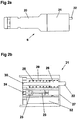
- the Grappler 6 consists of a Barrel assembly 21 , comprising a housing which may be produced from aluminium alloy and a Breech assembly 20, which may be produced from acetyl or other similar material. Both components 20 and 21 are preferably designed such that they are sealed to prevent water ingress and operate from 0 to 300 metres depth or more.
- the front mounted trigger 22 is activated and the Grappler 6 is attached to the target 4 by means of one or more high-tensile nails 23, which are fired (and retained) using a proprietary powder actuated impact tool cartridge 24.
- the illustrated cartridge is a rim activated cartridge. More specifically the Grappler 6 is an indirect acting tool that uses a retained piston 25 and captive nail 23 to transfer energy from a proprietary impact tool cartridge 24 to secure the grappler unit 6 to the desired target.
- the Trigger mechanism Contained in the Barrel Assembly 21 is the Trigger mechanism, which ultimately fires the Grappler 6.
- the trigger 22 is designed such that it is sealed to prevent water ingress into the housing.
- the trigger itself is a simple protrusion extending through a hole in the front wall 27 of the housing 21 .
- the trigger is retained in the housing by means of an annular collar 26 which is biased against the front wall 27 by means of a spring 28 captured in a chamber 29 within the housing 21 .
- the trigger may be direct acting as shown Fig 2b or may act by other means.
- Trigger 22 has a shaft 30 that extends through the chamber 29 and is integral with the trigger in this example.
- the collar 26 is sealed against the ingress of water into the chamber 29.
- FIG. 2c An alternative trigger mechanism is shown in Fig 2c .
- the trigger 22 is retained in a first chamber 31 and biased against the front wall 27 of the housing in a similar manner to the arrangement described above.
- a shaft 30 passes through a second chamber 35 separated from the first chamber 31 by a piston 32 attached to shaft 30.
- Air inlets 33 and 34 permit fluid to enter chambers 35 and 31 respectively.
- This trigger is inoperative in air, as air can be compressed, but when both chambers 31 and 35 are filled with water, as water is not compressible the trigger 22 is rendered operative.
- the trigger 22 When the trigger 22 is pressed, it moves past the port 34 forcing the volume of water in chamber 31 to move the Slave Piston 32 and fire the Grappler in a manner to be explained in more detail below.
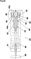
- the principal components of the breech assembly 20 are release bolt 40, tail plate 41 , striker 42, striker spring 43 and striker release sleeve 44.
- the release bolt 40 is coaxial with and attached to the striker 42.
- the striker release sleeve 44 is biased in the forward direction by means of spring 45 acting against an annular shoulder 46 on the sleeve 44.
- the striker 42 and hence the release bolt 40 are biased in the forward direction by means of striker spring 43 acting against an annular shoulder 48 provided on the striker 42.
- the striker 42 and spring 43 are surrounded by a striker sleeve 49 which is partially surrounded by the striker release sleeve 44.
- the striker sleeve 49 accommodates a number of ball bearings 50 in an annular configuration surrounding a front portion of the striker 42.
- the ball bearings are trapped between the striker 42 and the striker release sleeve 44 which have respective cam surfaces 42a and 44a whose function will be explained below.
- the breech assembly 20 and the barrel assembly 21 are separated from each other.
- the breech assembly 20 is then armed.
- an arming tool 60 is inserted through a hole in the tail plate 41 into the Breech assembly and connected into the Release Bolt 40, e.g. by means of a screw thread.
- the position of the release sleeve is controlled by the ball bearings 50 abutting against the cam surface 44a of the release sleeve 44.
- the Release Bolt 40 is then drawn back using the tool 60, which draws back the striker 42 and compresses the Striker Spring 43.
- the ball bearings travel down the cam surface 42a provided on the striker 42 enabling the striker release sleeve to move forward and lock the striker in the "armed" position shown in figure 2f .
- the cartridge 24 is then inserted into the end of the Barrel and the Barrel Housing 21 is then re-assembled onto the Breech housing 20.
- the two components may be screwed together.
- the Striker Release Sleeve is moved rearwardly allowing the balls 50 to travel outwardly along the cam surface 44a of the release sleeve 44.
- the Striker 42 is allowed to be released, a pin on the end of the striker strikes the rim of the cartridge 24 and the cartridge 24 is fired causing the Piston 25 to drive the Nail 23 through the end face 27 of the Barrel Housing and into the target.
- a Shunt Buffer 51 then arrests the Piston 25 and the explosive gasses are discharged into an Expansion Chamber 52 through a Discharge Port 53.
- the Grappler 6 is now securely attached to the target 4.
- a bungee or other line may be attached to the breech housing 20 so as to be released when the grappler is activated.
- a slot in the cylindrical part of the housing may enable a line to be passed around the release bolt 40 so as to be released when the bolt is in the forward position shown in figure 2g .
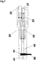
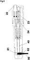
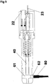
- the release of the bungee is illustrated more clearly in figures 6 , 7 and 8 . These figures show a slightly different embodiment of the invention which operates on the same principle as that described above and for which like parts are indicated by like reference numerals.
- the trigger 22 has a mushroom shaped head in this example.
- a cylindrical space 61 is present at the back of the breech assembly 20 through which the release bolt 40 passes.
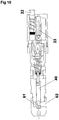
- a slot or hole 62 shown most clearly in figure 10 is provided in the outer wall of the breech assembly 20 permitting access to this space.
- a loop 80 of cord or other line may be fed into the space 61 so that when the release bolt is drawn back the bolt 40 passes through the loop 80.
- Figure 6 shows a loop 80 inserted into the space 61 and the release bolt drawn back. In this configuration, assuming the loop is closed, the cord is secured to the attachment device and an ROV or other object can be tied to the other end of the cord.
- Figure 7 shows the trigger 20 partially depressed and it will be seen that the release bolt has begun to travel towards the front of the attachment device, rightward in the figures.
- Figure 8 shows the trigger fully depressed. In this configuration the cartridge has been fired and the nail has been driven through the end of the housing. Further, the release bolt has 40 moved out of the space 61 completely. Now the loop 80 is released and can be removed as shown in figure 9 .
- something more rigid attached to a loop may be used, such as a hook of rigid material e.g. metal, which might be easier to feed into the space 61.
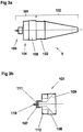
- the Disruptor 5 consists of a standoff cone, which may be produced in aluminium alloy, a copper charge cone and a charge fill chamber that may be produced in aluminium alloy. These items are hermetically sealed and able to operate up to a depth of 300 metres without impairment of operation. On the rear of the unit is a removable end cap that may be produced in high-density polyethylene or other material and a retainer to hold the detonator.
- the Disruptor may be filled with any proprietary plastic explosive such as PE4/C4.
- the Disruptor 5 is a self-fill shaped charge demolition device, the main components of which are the Charge Cap Assembly 101 and front section 102.
- the charge cap assembly comprises a detonator retention system 103 and Buoyancy Compensation 104.
- the Front Section 102 comprises a main energetic Chamber 105 and the Charge-Shaping Cone 106. These units may be separated to enable filling with PE4/C4 energetic material or similar.
- the Charge Cap Assembly 101 is first removed from the Front Section 102 and Detonator Retaining Cap 107 is removed from the Charge Cap 108.
- the charge cap provides a chamber 109 having a conical shape. PE4/C4 or other suitable energetic is formed/inserted into the Conical Chamber 109 in the Cap 108.
- a suitable detonator compatible with the plastic tube initiation system is positioned into a hole 110 in the Detonator Retaining Cap 107. This is typically a cylindrical object.
- a Rubber Retaining Ring 111 is slipped over the detonator to hold it in place.
- One or more Buoyancy Rings 112 are fixed into position on the Charge Cap 108.
- the Detonator Retaining Cap 107 With detonator in position, is then screwed into place on the charge cap 108 and the Rubber Retaining Ring 111 now safely retains the detonator in position.
- the Front Section 102 consists of the Standoff Cone 120 which positions the Disruptor 5 at the optimum distance for maximum penetration (approx twice the Charge Chamber 109 maximum diameter), the copper Charge Shaping Cone 121 , which forms the energetic to the correct angle and is of optimum mass for jet formation (approximately 2 % Charge Chamber diameter) and the Charge Chamber 122 which holds a measured amount of energetic.
- the Charge Chamber 122 is also filled with energetic material.
- the Front Section 102 and the Charge Cap Assembly 101 are now joined together. They may be joined by means of a screw thread.
- the charge chamber 122 and the charge cap 108 form a single chamber with forward and rear surfaces which both have a rearward facing conical shape.
- the Disruptor 5 is now prepared and ready.
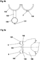
- the Hand-Held system which may be used in or out of water and may be hand held or deployed using the articulated arm of a ROV consists of a Grappler 6, which is restrained in a sleeve 130 using a screw 131 or other device and connected to a handle 132, which may be articulated, and a Manacle Clamp 133 or other similar device suitable to restrain a Disruptor 5 so that the faces of both devices (i.e. the Trigger Face on the grappler 6 and the nose of the Standoff Cone 120 of the Disruptor 5) are generally co-incident. As shown the end of the trigger 122 is slightly in front of the nose of the standoff cone.
- the plastic tube 7 from the detonator initiation system is restrained in a Strain Relief Clip 134.
- a detailed sketch of a suitable handle assembly is shown in Fig 4b .
- Manacle clamp 133 is shown hinged open, attached to the Handle ( Fig 4b - 2 ) which may be of articulated construction to enable adjustment of the direction of the Disruptor after attachment of the Grappler to the Target.
- the handle may enable rotation of the disruptor with respect to the grappler about the axis of the handle.
- the sleeve 130 that receives the Grappler 6 is appended with a Screw 131 or other device to lock the Grappler 6 into position relative to the Disruptor 5 and the plastic tube 7 is shown in the Strain Relief Clip 134.
- the Buoyancy Compensation Rings 112 ensure that, in water, the unit is slightly positively buoyant such that it would not adversely affect a swimmer or diver but if inadvertently released it would slowly drift to the surface and thus recoverable and not present a possible hazard to fishermen. Cowl
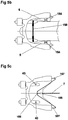
- the Cowl is shown in figures 5a to 5c and is of hydro dynamic shape to minimise drag through the water and is designed such that it interfaces with other proprietary ROV's and Sea Scooters or other vehicles and is compensated to achieve neutral buoyancy. As such it is in the shape of a generally conical collar.
- the cowl consists of a moulding of reinforced glass fibre or similar material with holders for the Grapplers 6 (usually two but at least one), manacle restraints for the Disruptors 5 and other clips and restraints to attach the proprietary plastic tube detonator initiation system 7.
- the Cowl is designed to e disposable. It is manufactured from glass reinforced fiberglass or other material in a hydrodynamic shape and such that it interfaces with the nose cone 151 of an ROV or Sea Scooter.
- Fig 5a shows a cowl 150 fitted with two Grapplers 6, which are slid into, and retained by, two sleeves 152 bonded into the Cowl 150.
- the Grapplers 6 are fitted with Buoyancy Compensation Rings and Trim Weights 153 to achieve neutral buoyancy.
- the Cowl is slid onto the front of the ROV and a bespoke Bungee Cord 158 is clipped on underneath joining both Release Bolts 40 on the Grapplers 6.
- the Cowl 150 is now ready for launch.
- the ROV 9 is driven at the target 4 to impact the Triggers 22 on the Grapplers 6. If either or both Grapplers 6 are fired the cowl 150 will detach from the ROV as a result of the bungee 158 being released from one or both of the grapplers. As the Cowl 150 is neutrally buoyant it will remain with its attitude stable until the
- Disruptors 5 are initiated.
- the ROV can then be moved to a safe distance and the Target 4 destroyed.
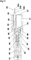
- the trigger also serves as a fastener, thereby avoiding the need for the nail and the use of explosive to drive the nail.
- the trigger mechanism is contained in the barrel assembly 21.
- the trigger 22 is designed such that it is sealed to prevent water ingress into the housing.
- the trigger is retained in the housing by means of an annular collar 26 which is biased against the front wall 27 by means of a spring 28 captured in a chamber 29 within the housing 21.
- the trigger may be direct acting or may act by other means.
- Trigger 22 has a shaft 30 that extends through the chamber 29 and is integral with the shaft in this example. The collar 26 is sealed against the ingress of water into the chamber 29.
- the trigger itself is a not a simple protrusion but is in the shape of a harpoon with barbs 22a designed so that once the trigger penetrates the surface of a target the barbs obstruct its removal.
- This device is designed for targets with thin or weak walls or skins that might crumble or be otherwise damaged by the impact of a fastener driven under explosive force.
- a possible design of faster is one with an "umbrella" head that opens once the fastener has penetrated the wall or skin of the target.
- Other possible fastener designs will occur to those skilled in the art.
- Such fasteners are also suitable to be driven in the manner of the nails of the previous examples.
- the trigger/fastener 22 shown in figure 11 has a collar 22b on the outside of the device housing which abuts against the surface of the housing when the release bolt 40 has moved forward out of the space 61 . At this point further pressure on the fastener will cause it to be driven into the target rather than the device housing. Indeed in all of the foregoing embodiments multiple triggers could be provided. This might be useful in turbulent conditions where accurate positioning to actuate one relatively small trigger is difficult. For the same reason the trigger might be provided with a large surface area for impact with the target, such as a larger mushroom shape than that shown in figures 6 to 10 .
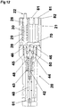
- the embodiment of attachment/release device shown in figure 12 comprises multiple fasteners in the form of magnets 80.
- this version has no nails and no cartridge detonation system to drive the nails.
- the trigger is a simple button. When the button is pressed towards the front of the housing this initiates a series of operations as with the device shown in figure 11 resulting in the forward movement of the release bolt 40 out of the space 61 at the rear of the device. With the trigger fully depressed the surface of the trigger is flush with the front face of the device as in the device shown in figure 2 . The magnets are then brought into contact with the surface of the target and become attached to it.
- Multiple magnets 80 may be provided. These may for example be arranged radially such that the magnetic flux is in a closed loop around the face of the device. An example of such an arrangement is shown in figure 13 . Here the magnets are arranged in a circle with opposite poles facing each other around the circle.
- a magnetic shield 82 is arranged around the front face and forward cylindrical surface. The purpose of this is to absorb any stray magnetic flux that may cause interference with the ROV navigation system (such as magnetic compass).
- the EOD disruptor/demolition device can be set off in sequence or simultaneously with other devices.
- the assemblies of attachment and disruptor enable a disruptor/demolition method that is less susceptible to stray electromagnetic and electrostatic energy than current methods.
- the device that can be quickly deployed and thus reduce the time an EOD technician must spend in the vicinity of the ordnance.
- the device has the capability for multiple option firing. Thanks to the grapplers a disruptor can be attached quickly and easily and does not require additional restraint.
- a grappler disruptor assembly is capable of attaching to a multiplicity of materials including but not exclusively steel, fibreglass, wood, plastic, brickwork and concrete. It can attach irrespective of surface condition including but not exclusively seaweed, slime, barnacles, rust, paint, tar, and plastic coatings.
- the disruptor is self-fill such that it is completely inert during transportation (the explosive being added by the user at time of deployment).
Landscapes
- Engineering & Computer Science (AREA)
- General Engineering & Computer Science (AREA)
- Aviation & Aerospace Engineering (AREA)
- Portable Nailing Machines And Staplers (AREA)
- Disintegrating Or Milling (AREA)
Applications Claiming Priority (2)
| Application Number | Priority Date | Filing Date | Title |
|---|---|---|---|
| GB1015812.9A GB2483861C (en) | 2010-09-21 | 2010-09-21 | Attachment device and assemblies and systems using same |
| EP11754719.0A EP2619524B1 (de) | 2010-09-21 | 2011-08-15 | Befestigungsvorrichtung sowie diese verwendende anordnungen und systeme |
Related Parent Applications (2)
| Application Number | Title | Priority Date | Filing Date |
|---|---|---|---|
| EP11754719.0A Division-Into EP2619524B1 (de) | 2010-09-21 | 2011-08-15 | Befestigungsvorrichtung sowie diese verwendende anordnungen und systeme |
| EP11754719.0A Division EP2619524B1 (de) | 2010-09-21 | 2011-08-15 | Befestigungsvorrichtung sowie diese verwendende anordnungen und systeme |
Publications (2)
| Publication Number | Publication Date |
|---|---|
| EP3318833A2 true EP3318833A2 (de) | 2018-05-09 |
| EP3318833A3 EP3318833A3 (de) | 2018-06-13 |
Family
ID=43065579
Family Applications (2)
| Application Number | Title | Priority Date | Filing Date |
|---|---|---|---|
| EP11754719.0A Revoked EP2619524B1 (de) | 2010-09-21 | 2011-08-15 | Befestigungsvorrichtung sowie diese verwendende anordnungen und systeme |
| EP17210135.4A Withdrawn EP3318833A3 (de) | 2010-09-21 | 2011-08-15 | Befestigungsvorrichtung sowie anordnungen damit |
Family Applications Before (1)
| Application Number | Title | Priority Date | Filing Date |
|---|---|---|---|
| EP11754719.0A Revoked EP2619524B1 (de) | 2010-09-21 | 2011-08-15 | Befestigungsvorrichtung sowie diese verwendende anordnungen und systeme |
Country Status (9)
| Country | Link |
|---|---|
| US (1) | US9677866B2 (de) |
| EP (2) | EP2619524B1 (de) |
| AU (1) | AU2011306719B2 (de) |
| CA (1) | CA2813051C (de) |
| DK (1) | DK2619524T3 (de) |
| GB (1) | GB2483861C (de) |
| LT (1) | LT2619524T (de) |
| PL (1) | PL2619524T3 (de) |
| WO (1) | WO2012038711A1 (de) |
Cited By (1)
| Publication number | Priority date | Publication date | Assignee | Title |
|---|---|---|---|---|
| EP3590820A1 (de) * | 2018-07-02 | 2020-01-08 | Saab Dynamics AB | System zur befestigung einer vorrichtung an ein objekt und zugehöriges system zur anwendung der vorrichtung |
Families Citing this family (13)
| Publication number | Priority date | Publication date | Assignee | Title |
|---|---|---|---|---|
| GB2480688B (en) * | 2010-05-28 | 2012-11-14 | Subsea 7 Contracting Norway As | Subsea position control system for elongate articles |
| DE102010033638A1 (de) * | 2010-08-06 | 2012-02-09 | Atlas Elektronik Gmbh | Kampfmittelräumgerät zum Räumen von Kampfmitteln, wie Seeminen, unter Wasser, unbemanntes Unterwasserfahrzeug mit derartigem Kampfmittelräumgerät sowie Verfahren hierzu |
| DE102011121856A1 (de) † | 2011-12-21 | 2013-06-27 | Atlas Elektronik Gmbh | Kampfmittelräumgerät zum Räumen von Kampfmitteln, wie Seeminen, unter Wasser, Kampfmittelräumkombination mit unbemanntem Unterwasserfahrzeug und derartigem Kampfmittelräumgerät sowie Verfahren hierzu. |
| DE102013106064A1 (de) * | 2013-06-11 | 2014-12-11 | Atlas Elektronik Gmbh | Vorrichtung und Verfahren zum Neutralisieren von Kampfmitteln |
| GB2517173A (en) * | 2013-08-13 | 2015-02-18 | Saab Seaeye Ltd | Charge deployment system for ordnance neutralisation |
| KR102124522B1 (ko) * | 2015-12-02 | 2020-06-19 | 마스 젠그란지 (엔제트) 리미티드 | 해양 부상 분리 디바이스 |
| DK3179202T3 (da) * | 2015-12-10 | 2019-07-01 | Saab Dynamics Ab | System til fastgørelse af en ladning til undervandskrigsmateriel og tilhørende system til anvendelse af apparatet |
| DE102018103753B4 (de) * | 2018-02-20 | 2022-06-30 | Heinrich Hirdes Gmbh | Vorrichtung und Verfahren zur Beseitigung eines nicht explo-dierten Kampfmittels unter Wasser |
| GB2578492B (en) * | 2019-03-29 | 2021-05-05 | Ecs Special Projects Ltd | A device for attaching to a target |
| US11609071B1 (en) | 2021-07-28 | 2023-03-21 | The United States Of America As Represented By The Secretary Of The Navy | Below/above-water remote energetic attachment kinetic kill rod(BREAKKR) projectile |
| CN115541421B (zh) * | 2022-09-26 | 2025-11-04 | 中国人民解放军陆军工程大学 | 混凝土结构水下爆破自主采集系统 |
| CN115541419B (zh) * | 2022-09-26 | 2025-09-26 | 中国人民解放军陆军工程大学 | 浅水中混凝土结构爆破效应试验装置 |
| DE102022125485B3 (de) | 2022-10-04 | 2023-05-11 | Heinrich Hirdes Gmbh | Sprengverfahren und Sprengvorrichtung zur Beseitigung eines nicht explodierten Kampfmittels |
Family Cites Families (23)
| Publication number | Priority date | Publication date | Assignee | Title |
|---|---|---|---|---|
| US1365869A (en) | 1919-10-10 | 1921-01-18 | Temple Robert | Rxplosively-actuated penetrating means |
| BE505746A (de) | 1951-07-18 | |||
| US2819674A (en) * | 1954-08-17 | 1958-01-14 | Prodanovich Jack | Underwater sport fishing gun and harpoon |
| US3013517A (en) * | 1959-06-02 | 1961-12-19 | Basil O Isham | Hook |
| US3497124A (en) * | 1967-06-29 | 1970-02-24 | Mine Safety Appliances Co | Stud-driving tool |
| US3554424A (en) * | 1968-07-19 | 1971-01-12 | Usm Corp | Push to fire explosive tools |
| US3880103A (en) * | 1972-08-21 | 1975-04-29 | Us Navy | Tethered mine hunting system |
| US4159070A (en) | 1975-09-26 | 1979-06-26 | Aai Corporation | Impact nailing arrangement |
| DE3147886C2 (de) * | 1981-12-03 | 1985-06-13 | Feinwerkbau Westinger & Altenburger GmbH & Co KG, 7238 Oberndorf | Elektrische Abzugsvorrichtung für Schußwaffen |
| DE3528329A1 (de) | 1985-08-07 | 1987-02-12 | Rheinmetall Gmbh | Einrichtung zur vernichtung von seeminen, insbesondere ankertauminen |
| SE8702854D0 (sv) * | 1986-07-03 | 1987-07-02 | British Aerospace | Explosiv anordning |
| DE3826653C1 (de) * | 1988-08-05 | 1989-12-07 | Rheinmetall Gmbh, 4000 Duesseldorf, De | |
| DE3915577A1 (de) * | 1989-05-12 | 1990-11-15 | Rheinmetall Gmbh | Vorrichtung zur vernichtung von ankertauminen |
| US5038665A (en) | 1990-02-02 | 1991-08-13 | Honeywell Inc. | Silent stud gun attachment device |
| US5083392A (en) * | 1990-07-16 | 1992-01-28 | Bookstaber Richard M | Firearm with piezo-electric triggering and firing mechanism |
| GB2251785B (en) | 1991-01-16 | 1994-07-13 | Huang Yu Hwei | Keyring assembly |
| US5425488A (en) * | 1993-11-05 | 1995-06-20 | Thompson William J | Impact actuated tool for driving fasteners |
| US5831199A (en) | 1997-05-29 | 1998-11-03 | James McNulty, Jr. | Weapon for immobilization and capture |
| US5943806A (en) * | 1997-12-02 | 1999-08-31 | Underwood; John V. | Shark gun |
| EP0971199A1 (de) * | 1998-07-06 | 2000-01-12 | SM Schweizerische Munitionsunternehmung AG | Vorrichtung zur Beseitigung von Kampfmitteln |
| DE102004045532B3 (de) * | 2004-09-20 | 2006-02-02 | Atlas Elektronik Gmbh | Verfahren zur Vernichtung einer lokalisierten Mine |
| FR2882339B1 (fr) * | 2005-02-21 | 2008-09-12 | Dcn Sa | Procede et dispositif d'identification et de neutralisation d'une mine sous-marine |
| DE102010033638A1 (de) | 2010-08-06 | 2012-02-09 | Atlas Elektronik Gmbh | Kampfmittelräumgerät zum Räumen von Kampfmitteln, wie Seeminen, unter Wasser, unbemanntes Unterwasserfahrzeug mit derartigem Kampfmittelräumgerät sowie Verfahren hierzu |
-
2010
- 2010-09-21 GB GB1015812.9A patent/GB2483861C/en active Active
-
2011
- 2011-08-15 CA CA2813051A patent/CA2813051C/en active Active
- 2011-08-15 EP EP11754719.0A patent/EP2619524B1/de not_active Revoked
- 2011-08-15 US US13/825,512 patent/US9677866B2/en active Active
- 2011-08-15 LT LTEP11754719.0T patent/LT2619524T/lt unknown
- 2011-08-15 DK DK11754719.0T patent/DK2619524T3/en active
- 2011-08-15 EP EP17210135.4A patent/EP3318833A3/de not_active Withdrawn
- 2011-08-15 WO PCT/GB2011/051541 patent/WO2012038711A1/en not_active Ceased
- 2011-08-15 PL PL11754719T patent/PL2619524T3/pl unknown
- 2011-08-15 AU AU2011306719A patent/AU2011306719B2/en active Active
Non-Patent Citations (1)
| Title |
|---|
| None |
Cited By (4)
| Publication number | Priority date | Publication date | Assignee | Title |
|---|---|---|---|---|
| EP3590820A1 (de) * | 2018-07-02 | 2020-01-08 | Saab Dynamics AB | System zur befestigung einer vorrichtung an ein objekt und zugehöriges system zur anwendung der vorrichtung |
| WO2020007849A1 (en) * | 2018-07-02 | 2020-01-09 | Saab Dynamics Ab | System for attaching a device to an object, and associated system for deploying the device |
| US11679850B2 (en) | 2018-07-02 | 2023-06-20 | Saab Dynamics Ab | System for attaching a device to an object, and associated system for deploying the device |
| AU2019297367B2 (en) * | 2018-07-02 | 2025-05-08 | Saab Dynamics Ab | System for attaching a device to an object, and associated system for deploying the device |
Also Published As
| Publication number | Publication date |
|---|---|
| EP2619524B1 (de) | 2018-12-26 |
| CA2813051C (en) | 2016-09-13 |
| WO2012038711A1 (en) | 2012-03-29 |
| EP3318833A3 (de) | 2018-06-13 |
| EP2619524A1 (de) | 2013-07-31 |
| US20140083282A9 (en) | 2014-03-27 |
| GB2483861B (en) | 2013-01-23 |
| US9677866B2 (en) | 2017-06-13 |
| CA2813051A1 (en) | 2012-03-29 |
| AU2011306719B2 (en) | 2015-10-08 |
| GB2483861A (en) | 2012-03-28 |
| US20130199358A1 (en) | 2013-08-08 |
| DK2619524T3 (en) | 2019-04-01 |
| GB2483861C (en) | 2019-01-30 |
| AU2011306719A1 (en) | 2013-04-11 |
| PL2619524T3 (pl) | 2019-06-28 |
| LT2619524T (lt) | 2019-03-12 |
| GB201015812D0 (en) | 2010-10-27 |
Similar Documents
| Publication | Publication Date | Title |
|---|---|---|
| CA2813051C (en) | Attachment/release device and assemblies and systems using same | |
| US8807002B2 (en) | Weapon clearance appliance for clearing weapons, such as underwater mines, under water, unmanned underwater vehicle having a weapon clearance appliance of this kind, and method for this purpose | |
| US5341718A (en) | Launched torpedo decoy | |
| EP3033270B1 (de) | Ladungseinsatzsystem für artillerieneutralisierung | |
| US9187161B2 (en) | Weapon clearance appliance for clearing weapons, such as underwater mines, under water, unmanned underwater vehicle having a weapon clearance appliance of this kind, and method for this purpose | |
| US5951346A (en) | Air-delivered position marking device and method | |
| US4505018A (en) | Underwater stud gun system and method for attaching an article to an underwater structure | |
| US12179895B2 (en) | Explosive container | |
| US5973994A (en) | Surface launched sonobuoy | |
| US6401591B1 (en) | Neutralization chemical injection penetrator | |
| EP3179202B1 (de) | System zur befestigung einer ladung an unterwasserkampfmittel und zugehöriges system zum ausbringen der vorrichtung | |
| GB2578492A (en) | A device for attaching to a target | |
| US3477525A (en) | Hard sediment gun corer | |
| US4966079A (en) | Ice penetrating moored mine | |
| US3326172A (en) | Explosive cutter for moored mine cables | |
| EP3887242B1 (de) | Unterwasserfahrzeug mit richteffektor | |
| WO2012051604A2 (en) | Underwater neutralization system | |
| CA3104203A1 (en) | System for attaching a device to an object, and associated system for deploying the device |
Legal Events
| Date | Code | Title | Description |
|---|---|---|---|
| PUAI | Public reference made under article 153(3) epc to a published international application that has entered the european phase |
Free format text: ORIGINAL CODE: 0009012 |
|
| AC | Divisional application: reference to earlier application |
Ref document number: 2619524 Country of ref document: EP Kind code of ref document: P |
|
| AK | Designated contracting states |
Kind code of ref document: A2 Designated state(s): AL AT BE BG CH CY CZ DE DK EE ES FI FR GB GR HR HU IE IS IT LI LT LU LV MC MK MT NL NO PL PT RO RS SE SI SK SM TR |
|
| PUAL | Search report despatched |
Free format text: ORIGINAL CODE: 0009013 |
|
| AK | Designated contracting states |
Kind code of ref document: A3 Designated state(s): AL AT BE BG CH CY CZ DE DK EE ES FI FR GB GR HR HU IE IS IT LI LT LU LV MC MK MT NL NO PL PT RO RS SE SI SK SM TR |
|
| RIC1 | Information provided on ipc code assigned before grant |
Ipc: F42D 5/04 20060101AFI20180509BHEP Ipc: B63G 7/02 20060101ALI20180509BHEP |
|
| RAP1 | Party data changed (applicant data changed or rights of an application transferred) |
Owner name: ATLAS ELEKTRONIK GMBH |
|
| STAA | Information on the status of an ep patent application or granted ep patent |
Free format text: STATUS: THE APPLICATION IS DEEMED TO BE WITHDRAWN |
|
| 18D | Application deemed to be withdrawn |
Effective date: 20181214 |