EP3318480A1 - Endlosfaserverstärkung zur luftschiffkonstruktion - Google Patents
Endlosfaserverstärkung zur luftschiffkonstruktion Download PDFInfo
- Publication number
- EP3318480A1 EP3318480A1 EP17199570.7A EP17199570A EP3318480A1 EP 3318480 A1 EP3318480 A1 EP 3318480A1 EP 17199570 A EP17199570 A EP 17199570A EP 3318480 A1 EP3318480 A1 EP 3318480A1
- Authority
- EP
- European Patent Office
- Prior art keywords
- gas
- fibers
- shape
- filled shape
- filled
- Prior art date
- Legal status (The legal status is an assumption and is not a legal conclusion. Google has not performed a legal analysis and makes no representation as to the accuracy of the status listed.)
- Granted
Links
Images

Classifications
-
- B—PERFORMING OPERATIONS; TRANSPORTING
- B29—WORKING OF PLASTICS; WORKING OF SUBSTANCES IN A PLASTIC STATE IN GENERAL
- B29C—SHAPING OR JOINING OF PLASTICS; SHAPING OF MATERIAL IN A PLASTIC STATE, NOT OTHERWISE PROVIDED FOR; AFTER-TREATMENT OF THE SHAPED PRODUCTS, e.g. REPAIRING
- B29C70/00—Shaping composites, i.e. plastics material comprising reinforcements, fillers or preformed parts, e.g. inserts
- B29C70/04—Shaping composites, i.e. plastics material comprising reinforcements, fillers or preformed parts, e.g. inserts comprising reinforcements only, e.g. self-reinforcing plastics
- B29C70/28—Shaping operations therefor
- B29C70/30—Shaping by lay-up, i.e. applying fibres, tape or broadsheet on a mould, former or core; Shaping by spray-up, i.e. spraying of fibres on a mould, former or core
-
- B—PERFORMING OPERATIONS; TRANSPORTING
- B05—SPRAYING OR ATOMISING IN GENERAL; APPLYING FLUENT MATERIALS TO SURFACES, IN GENERAL
- B05D—PROCESSES FOR APPLYING FLUENT MATERIALS TO SURFACES, IN GENERAL
- B05D1/00—Processes for applying liquids or other fluent materials
- B05D1/02—Processes for applying liquids or other fluent materials performed by spraying
-
- B—PERFORMING OPERATIONS; TRANSPORTING
- B64—AIRCRAFT; AVIATION; COSMONAUTICS
- B64B—LIGHTER-THAN AIR AIRCRAFT
- B64B1/00—Lighter-than-air aircraft
- B64B1/02—Non-rigid airships
-
- B—PERFORMING OPERATIONS; TRANSPORTING
- B64—AIRCRAFT; AVIATION; COSMONAUTICS
- B64B—LIGHTER-THAN AIR AIRCRAFT
- B64B1/00—Lighter-than-air aircraft
- B64B1/06—Rigid airships; Semi-rigid airships
- B64B1/14—Outer covering
-
- B—PERFORMING OPERATIONS; TRANSPORTING
- B64—AIRCRAFT; AVIATION; COSMONAUTICS
- B64B—LIGHTER-THAN AIR AIRCRAFT
- B64B1/00—Lighter-than-air aircraft
- B64B1/58—Arrangements or construction of gas-bags; Filling arrangements
-
- G—PHYSICS
- G09—EDUCATION; CRYPTOGRAPHY; DISPLAY; ADVERTISING; SEALS
- G09F—DISPLAYING; ADVERTISING; SIGNS; LABELS OR NAME-PLATES; SEALS
- G09F21/00—Mobile visual advertising
- G09F21/06—Mobile visual advertising by aeroplanes, airships, balloons, or kites
-
- B—PERFORMING OPERATIONS; TRANSPORTING
- B29—WORKING OF PLASTICS; WORKING OF SUBSTANCES IN A PLASTIC STATE IN GENERAL
- B29L—INDEXING SCHEME ASSOCIATED WITH SUBCLASS B29C, RELATING TO PARTICULAR ARTICLES
- B29L2031/00—Other particular articles
- B29L2031/30—Vehicles, e.g. ships or aircraft, or body parts thereof
- B29L2031/3067—Ships
- B29L2031/307—Hulls
-
- B—PERFORMING OPERATIONS; TRANSPORTING
- B64—AIRCRAFT; AVIATION; COSMONAUTICS
- B64B—LIGHTER-THAN AIR AIRCRAFT
- B64B2201/00—Hybrid airships, i.e. airships where lift is generated aerodynamically and statically
Definitions
- the present disclosure relates, in general, to airship construction and, more particularly, to continuous fiber reinforcement of airship construction.
- an airship hull comprises a gas-filled shape fabricated from a membrane.
- the airship hull comprises one or more fibers applied to an outer surface of the gas-filled shape in a continuous manner such that a particular one of the one or more fibers wraps around a circumference of the gas-filled shape multiple times.
- the applied one or more fibers are: applied in a helical pattern, the helical pattern having a helical angle within a range of 40 degrees to 60 degrees when measured relative to a forward direction of the gas-filled shape; affixed to the outer surface of the gas-filled shape; and coated with one of a film or spray coating.
- a method for continuous fiber reinforcement of airship construction comprises fabricating a gas-filled shape from a membrane.
- the method comprises applying one or more fibers to an outer surface of the gas-filled shape in a continuous manner such that a particular one of the one or more fibers wraps around a circumference of the gas-filled shape multiple times.
- the method comprises affixing the applied one or more fibers to the outer surface of the gas-filled shape.
- hulls constructed with continuous fiber reinforcement may be lighter than traditional designs.
- hulls constructed with continuous fiber reinforcement may be stronger than traditional designs.
- hulls constructed with continuous fiber reinforcement may be easier to build than traditional designs.
- Other advantages may be readily apparent to one having skill in the art. Certain embodiments may have none, some, or all of the recited advantages.
- airships As described above, existing approaches to construction of airships, aerostats, and other lighter-than-air craft (referred to generally herein as airships) rely on structural joints to transform flat materials into three-dimensional, gas-tight volumes. These existing approaches, however, suffer from certain deficiencies.
- One such deficiency relates to the way in which the materials used to form the hulls of the craft are treated.
- the material used to construct the hulls is often manufactured using weavers or looms using one or more kinds of fibers, which may run in multiple directions.
- the material constructed using the looms and weavers may then be run through a series of processes to laminate films onto the material and/or treat the material with different coatings.
- the end result is a material that is very strong, gas-tight (e.g., to helium leakage) and resistant to sunlight, rain and other elements.
- this material is cut into pieces (commonly referred to as gores) based on the desired shape of the airship hull being constructed.
- gores the material coming off of the looms is formed from very strong fibers. In cases where the fibers themselves are extremely strong, it is desirable for them to be continuous. Cutting the material into gores therefore degrades the structural integrity of the material.
- the gore pieces are joined to make a three-dimensional shape, the gore pieces are joined together through processes such as welding (often using a strip of the same material as the gores).
- the process of assembling the airship hull according to existing approaches has further deleterious effects on the material.
- the individual gore pieces must be joined together in order to form the final shape of the airship hull.
- the gore pieces are joined together using a strip of material placed on top of the gore pieces at a seam and welded together (using, for example, heat welding or similar processes).
- the shape must be sealed and filled with a gas (such as air or helium), and the requisite quality checks must be performed to ensure that leaks are located and repaired. This further increases the amount of time and effort required to construct the final airship.
- a gas such as air or helium
- the present disclosure contemplates various embodiments that may address these and other deficiencies associated with existing approaches to airship construction.
- the various embodiments described herein improve on typical airship construction by eliminating structural joints through the use of continuous fiber reinforcement across the three-dimensional surface of the airship or aerostat hull.
- a membrane of thin film or fabric, built in the desired hull shape is filled with gas and suspended above the floor.
- Reinforcement fibers are applied to the outer surface, for example using self-propelled fiber placement devices that travel on the membrane surface.
- the fibers may be applied in a helical manner.
- the reinforcement fibers are fixed to the underlying hull surface at both ends, for example using adhesive bonding or mechanical anchoring.
- the length of a single fiber is large enough to wrap around the circumference multiple times, effectively eliminating structural joints across the hull assembly.
- an airship hull comprises a gas-filled shape fabricated from a membrane, and one or more fibers applied to an outer surface of the gas-filled shape in a continuous manner such that a particular one of the one or more fibers wraps around a circumference of the gas-filled shape multiple times.
- the applied one or more fibers may be applied in a helical pattern.
- the helical pattern may have a helical angle within a range of 40 degrees to 60 degrees when measured relative to a forward direction of the gas-filled shape.
- the applied one or more fibers are affixed to the outer surface of the gas-filled shape, and coated with one of a film or spray coating.
- the applied one or more fibers may be affixed to the outer surface of the gas-tight shape by one or more of mechanical anchoring of the one or more fibers to an end of the gas-filled shape and using adhesive.
- a method for continuous fiber reinforcement of airship construction is disclosed.
- a gas-filled shape is fabricated from a membrane.
- the gas-filled shape may comprise an airship hull, and may be gas-tight.
- One or more fibers are applied to an outer surface of the gas-filled shape in a continuous manner such that a particular one of the one or more fibers wraps around a circumference of the gas-filled shape multiple times.
- the one or more fibers may be applied in any suitable manner.
- the one or more fibers may be applied to the outer surface of the gas-filled shape by suspending the gas-filled shape in the air and rotating the gas-filled shape during application of the one or more fibers.
- the one or more fibers may be applied to the outer surface of the gas-filled shape using one or more fiber placement devices on the outer surface of the gas-filled shape, as described in detail below.
- the one or more fibers may be applied in a helical pattern, such as a helical pattern having a helical angle within a range of 40 to 60 degrees when measured relative to a forward direction of the gas-filled shape.
- the applied one or more fibers are affixed to the outer surface of the gas-filled shape.
- hulls constructed with continuous fiber reinforcement may be lighter than traditional designs.
- hulls constructed with continuous fiber reinforcement may be stronger than traditional designs.
- hulls constructed with continuous fiber reinforcement may be easier to build than traditional designs.
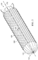
- Figure 1 illustrates an example of a gas-filled membrane, in accordance with certain embodiments. More particularly, Figure 1 illustrates a gas-filled membrane in the shape of an airship hull 105.
- Airship hull 105 is formed from a membrane 110, and has a first end 115 and a second end 120. Although airship hull 105 is shown in the example of Figure 1 as having particular dimensions, the present disclosure contemplates that airship hull 105 may have any suitable dimensions.
- Membrane 110 may be made from any suitable material, such as, for example, a high-performance film capable of creating a suitable gas barrier and providing protection from the environment. In some cases, membrane 110 may be formed from a single kind of material. In some cases, membrane 110 may be formed from a plurality of different materials. In certain embodiments, membrane 110 may be formed from MYLAR. In certain embodiments, membrane 110 may be treated with one or more resins, for example with a urethane resin.
- membrane 110 may have any suitable shape.
- the various embodiments described herein are not limited to the example illustrated in Figure 1 .
- membrane 110 may be formed from a film capable of creating a suitable gas barrier. This is desirable in that airships and aerostats, in order to function properly, must be able to retain the gasses with which they are filled.
- the material from which membrane 110 is formed may vary depending on the type of gas intended to be used with membrane 110.
- the present disclosure contemplates that membrane 110 may be filled with any suitable gas. For example, in certain embodiments membrane 110 may be filled with helium.
- membrane 110 is a lighter-weight film used to construct the gas-filled volume of airship hull 105.
- membrane 110 is not strong enough yet to support airship hull 105 in use, but it is sufficiently strong to hold the yield (i.e., gas) during the continuous fiber reinforcement process, described in detail below with respect to Figures 2-5 .
- Figure 2 illustrates an example of continuous fiber reinforcement of the gas-filled membrane of Figure 1 , in accordance with certain embodiments. Similar to Figure 1 , Figure 2 illustrates airship hull 105 formed from membrane 110. In addition, Figure 2 illustrates an example of airship hull 105 in which a fiber 205 has been applied in a continuous manner to reinforce membrane 110.
- Fiber 205 may be formed from any suitable materials. In some cases, fiber 205 may be formed from a single material. In some cases, fiber 205 may be formed from a plurality of different materials. For example, in certain embodiments fiber 205 may be formed from one or more of polyester, aramid, polyethylene, carbon materials, one or more resins (e.g., urethane), and any other suitable material.
- fiber 205 may be formed from one or more of polyester, aramid, polyethylene, carbon materials, one or more resins (e.g., urethane), and any other suitable material.
- Fiber 205 may be applied in any suitable configuration. In certain embodiments, a single fiber 205 may be applied to the outer surface of membrane 110. In certain embodiments, multiple fibers 205 may be applied to the outer surface of membrane 110.
- fiber 205 may be applied in a helical pattern.
- fiber 205 may be applied continuously without stopping and starting again.
- fiber 205 is wound around the outer surface of membrane 110 in a helical pattern having a helical angle 210 relative to longitudinal axis 215 within the range of 40 to 60 degrees when measured relative to a forward direction of airship hull 105 (e.g., towards first end 115).
- helical angle 210 may be 54 degrees.
- fiber 205 may be anchored at one one or more ends of airship hull 105.
- fiber 205 is anchored at first end 115 and at second end 120.
- Fiber 205 may be anchored in any suitable manner.
- a structure such as a steel cable ring, may be coupled to first end 115 of airship hull 105, and fiber 205 may be attached to the structure, for example by tying the fiber to the structure.
- fiber 205 may be wound around the outer surface of membrane 110 until a particular target point is reached (e.g., the nose of airship hull 105 at first end 115) and then fiber 205 may be bonded to the outer surface of membrane 110.
- Fiber 205 may be bonded to the outer surface in any suitable manner.
- fiber 205 may be bonded to the outer surface of membrane 110 using an adhesive or resin.
- fiber 205 may only be bonded over a large enough distance to allow fiber 205 to be substantially anchored.
- fiber 205 may be coated using a film or spray coating.
- fiber 205 may be performed in any suitable manner.
- fiber 205 may be applied while airship hull 105 is suspended in the air.
- fiber 205 may be applied using one or more fiber placement devices.
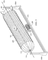
- Figure 3 illustrates an exemplary approach for applying continuous fiber reinforcement to the gas-filled membrane, in accordance with certain embodiments. Similar to Figures 1 and 2 described above, Figure 3 illustrates airship hull 105 formed from membrane 110. Airship hull 105 has a first end 115 and a second end 120. In the example of Figure 3 , fibers have been applied to the outer surface of membrane 110 using continuous fiber reinforcement. Figure 3 also illustrates additional elements that may be used in the process of continuous fiber reinforcement of airship hull 105, including supports 305A and 305B, a spool 310, and a track 315. Supports 305A, 305B, spool 310, and tracks 315 may be made of any suitable material and may have any suitable dimensions.
- supports 305A and 305B are located at opposite ends of airship hull 105.
- Supports 305A and 305B are configured to suspend airship hull 105 off the ground, for example during application of continuous fiber reinforcement.
- Support 305A is coupled to second end 120 of airship hull 105.
- Support 305B is coupled to first end 115 of airship hull 105.
- supports 305A and 305B may be rotatably coupled to second end 120 and first end 115, respectively, such that airship hull 105 can be rotated around its longitudinal axis 215 (similar to the action of a rotisserie). Rotation of airship hull 105 using supports 305A and 305B may be accomplished in any suitable manner.
- one or more of supports 305A and 305B may be fitted with a motor configured to rotate airship hull 105.
- Spool 310 is coupled to track 315 in any suitable manner.
- spool 310 may be configured to engage with track 315 and move from its illustrated position toward first end 115 of airship hull 105 and toward second end 120 of airship hull 105, as and when required.
- Spool 310 may move along track 315 in any suitable manner.
- spool 310 may be equipped with a motor operable to propel spool 310 back and forth along track 315. The movement of spool 310 along track 315 may be controlled in any suitable manner.
- spool 310 may include appropriate hardware and/or software to allow the movements of spool 310 along track 315 to be controlled by a computer over a wired and/or wireless connection.
- the movement of spool 310 along track 315 may be controlled by an individual guiding spool 310 on track 315.
- spool 310 includes multiple layers of fiber 205.
- fiber 205 can be formed from any suitable material.
- fiber 205 may be formed from one or more of polyester, aramid, polyethylene, carbon materials, one or more resins (e.g., urethane), and any other suitable material.
- fiber 205 may be wound onto spool 310.
- Spool 310 having fiber 205 may be fitted onto track 315 such that fiber 205 wound on spool 310 can be used for continuous fiber reinforcement of airship hull 105.
- spool 310 may be positioned relative to track 315 such that spool 310 can rotate (e.g., to dispense fiber 205) during movement along track 315.
- Figure 3 illustrates the use of spool 310, the present disclosure contemplates that any suitable device for dispensing fiber 205 may be used.
- track 315 may be a stand-alone piece separate from supports 305A and 305B.
- Track 315 may be made of any suitable materials.
- the length of track 315 may be adjustable to suit the different lengths of various airship hulls 105.
- supports 305A and 305B are rotatably coupled to second end 120 and first end 115, respectively, of airship hull 105.
- spool 310 loaded with fiber 205 is coupled to track 315.
- a loose end of fiber 205 loaded onto spool 310 may be affixed to the outer surface of membrane 110.
- Rotation of airship hull 105 around its longitudinal axis 215 is initiated (for example, by turning on a motor associated with supports 305A and 305B).
- spool 310 engaged with track 315 may begin to dispense fiber 205 as it moves along track 315.
- spool 310 begins moving from a point near second end 120 of airship hull 105 toward first end 115 of airship hull 105.
- fiber 205 is dispensed from spool 310 and applied to the outer surface of membrane 110 as airship hull 105 rotates.
- fiber 205 may wrap around airship hull 105 multiple times as spool 310 moves toward first end 115.
- spool 310 may move all the way to first end 115 of airship hull 105 before changing direction and traveling back toward second end 120 of airship hull 105. In certain embodiments, depending, for example, on the extent of continuous fiber reinforcement desired, spool 310 may travel less than the entire distance to first end 115 of airship hull 105 before traveling back toward second end 120 of airship hull 105. As spool 310 travels back toward second end 120 of airship hull 105, fiber 205 may continue to be dispensed. This process may be repeated until a desired degree of continuous fiber reinforcement has been achieved.
- the size of spool 310 may accommodate a significant amount of fiber 205, such that a single spool 310 of fiber 205 may be used to provide continuous fiber reinforcement for airship hull 105.
- the size of airship hull 105 may require more than one spool 310 of fiber 205 to be used.
- the second loose end of fiber 205 may be affixed to membrane 110 of airship hull 105, for example using a suitable adhesive or form of mechanical anchoring.
- a second spool 310 may be loaded onto track 315 and the process may resume at the point where the first spool left off, continuing to apply fiber 205 to airship hull 105.
- Fiber 205 may be applied in any suitable pattern.
- the rotation of airship hull 105 in combination with the movement of spool 310 along track 315 results the application of fiber 205 in a helical pattern.
- the helical angle 210 of the helical pattern of fiber 205 may have an angle between the range of 40 and 60 degrees.
- the helical angle 210 relative may be 54 degrees when measured relative to a forward direction of airship hull 105 (for example, toward one of first end 115 and second end 120).
- Figure 3 merely illustrates one example embodiment for the application of continuous fiber reinforcement to airship hull 105.
- Other means of applying fiber 205 are possible, and are within the scope of the various embodiments described herein.
- a single support 305 may be used to suspend airship hull 105 such that first end 115 of airship hull 105 is coupled to support 305.
- Support 305 may be configured to suspend airship hull 105 above the ground, similar to a crane.
- Track 315 rather than running beneath airship hull 105 as depicted in the example of Figure 3 , may run vertically alongside suspended airship hull 105.
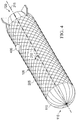
- Figure 4 illustrates another exemplary approach for applying continuous fiber reinforcement to the gas-filled shape, in accordance with certain embodiments.
- Figure 4 illustrates airship hull 105 formed from membrane 110.
- One or more fibers 205 have been applied to airship hull 105 (more specifically, to the outer surface of membrane 110) from first end 115 to second end 120 of airship hull 105.
- fiber 205 were applied by rotating airship hull 105 to allow fiber 205 to be applied multiple times around the circumference of airship hull 105.
- fiber 205 may, however, be instances in which it is not practical to suspend and rotate airship hull 105.
- the size of airship hull 105 may be so large that it is no longer desirable to apply the continuous fiber reinforcement in such a manner.
- fiber 205 may be applied using a fiber placement device 405.
- Fiber placement device 405 may be any suitable system capable of traversing the surface of membrane 110 forming airship hull 105 to apply one or more fibers 205.
- fiber placement device 405 may be a self-propelled device that travels on the surface of membrane 110, such as the airship hull repair system described in U.S. Patent No. 8,800,628 , which is hereby incorporated by reference in its entirety.
- fiber placement device 405 may be configured to move across airship hull 105 (or the hull of a similar craft, such as a dirigible, blimp, hybrid airship, aerostat, or other lighter-than-air craft).
- Fiber placement device 405 may include an exterior piece configured to move on the outer surface of membrane 110 and an interior piece configured to move on an interior of membrane 110.
- a magnetic coupling couples the exterior piece to the interior piece so that the pieces move together.
- the magnetic coupling can include at least one magnet in each of the exterior piece and the interior piece.
- the magnetic coupling can include at least one magnet in one of the pieces and a magnetically active material in the other one of the pieces.
- the magnets can be permanent magnets or electromagnets. Any other type of magnetic coupling can be used.
- Each piece of fiber placement device 405 includes a mechanism permitting motion across membrane 110.
- fiber placement device 405 may include wheels for the exterior piece and wheels for the interior piece. However, the disclosure is not limited to wheels.
- fiber placement device 405 may use rollers, tracks, balls, or any other type of mechanism that permits motion across membrane 110.
- fiber placement device 405 may include a power source, a drive subsystem, a damage detecting subsystem, a hull repair subsystem, a positioning subsystem, a damage reporting subsystem, and/or a control subsystem. In alternative aspects, fewer than all of these elements can be included, and additional elements can be included as well.
- the power source provides power for the subsystems that require power. In addition, if the magnetic coupling of the interior piece includes one or more electromagnets, then the power source can provide power for those electromagnets.
- the drive subsystem is configured to move fiber placement device 405 across airship hull 105.
- the drive subsystem directly drives the interior piece across the interior of membrane 110.
- the movement of the interior piece in turn moves the exterior piece by virtue of the magnetic coupling between the pieces.
- this magnetic coupling allows the interior piece to move across the top and sides of the hull including while inverted.
- the drive subsystem can be included in the exterior piece.
- the positioning subsystem can include accelerometers that determine the location of fiber placement device 405 based on movement of the system.
- the positioning subsystem can include a transmitter and receiver, with the position of the system triangulated by an external locator system based on transmitted signals and then transmitted back to the positioning subsystem.
- the positioning subsystem can include a video camera that shows an area surrounding fiber placement device 405. Images from the video camera can be viewed by an operator to determine a position of the system. Any other form of positioning subsystem can be used, alone or in conjunction with some or all of these examples.
- Fiber placement device 405 may be outfitted with a fiber dispenser, such as a spool similar to spool 315 described above with respect to Figure 3 , to allow fiber placement device 405 to dispense fiber 205 during application of continuous fiber reinforcement to airship hull 105.
- the exterior piece and interior piece of fiber placement device 405 may include various other pieces.
- fiber placement device 405 may have an interior and exterior cover to protect fiber placement device 405 and function as an aerodynamic faring.
- Fiber placement device 405 takes place much as described above with respect to Figure 3 .
- a loose end of fiber 205 loaded onto a fiber dispenser associated with fiber placement device 405 may be affixed to the outer surface of membrane 110.
- Fiber placement device 405, propelled by the drive subsystem traverses the outer surface of membrane 110 (guided, for example, by the positioning subsystem described above).
- a spool (similar to spool 310 described above with respect to Figure 3 ) dispenses fiber 205 on the outer surface of membrane 110.
- Fiber 205 may be applied in any suitable pattern.
- the movement of fiber placement device 405 across the outer surface of membrane 110 results in the application of fiber 205 in a helical pattern.
- the helical angle 210 relative to longitudinal axis 215 of the helical pattern of fiber 205 may have an angle between the range of 40 and 60 degrees.
- the helical angle 210 may be 54 degrees when measured relative to a forward direction of airship hull 105 (for example, toward one of first end 115 and second end 120).
- Figure 4 illustrates a single fiber placement device 405, the present disclosure contemplates that any suitable number of fiber placement devices 405 could be used in the continuous fiber reinforcement of airship hull 105.
- multiple fiber placement devices 405 could travel around airship hull 105 simultaneously, and thereby build up an airship hull fairly quickly.
- multiple fibers 205 may be applied to the outer surface of membrane 110.
- the fibers may be glued in place (or otherwise anchored) and a film or spray coating may be applied on the outer surface to encapsulate fibers 205. This may advantageously protect the applied fiber 205 from the environment.
- fiber 205 may be applied in any suitable amount.
- fiber 205 can be wound sparsely around airship hull 105 with only a small amount of fiber 205 being applied.
- a much larger amount of fiber 205 can be applied, for example by allowing the systems described above with respect to Figures 3 and 4 to run for longer periods of time.
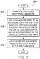
- Figure 5 is a flow diagram of a method 500 for continuous fiber reinforcement of airship construction, in accordance with certain embodiments.
- Method 500 begins at step 504, where a gas-filled shape is fabricated from a membrane.
- the gas-filled shape may comprise an airship hull.
- the gas-filled shape fabricated from the membrane may be gas-tight.
- one or more fibers are applied to an outer surface of the gas-filled shape in a continuous manner such that a particular one of the one or more fibers wraps around a circumference of the gas-filled shape multiple times.
- applying one or more fibers to the outer surface of the gas-filled shape may comprise: suspending the gas-filled shape in the air; and rotating the gas-filled shape during application of the one or more fibers.
- applying one or more fibers to the outer surface of the gas-filled shape may comprise: positioning at least one fiber placement device on the outer surface of the gas-filled shape, the fiber placement device coupled across the membrane to an internal component and comprising a fiber dispenser for dispensing the one or more fibers; and applying the one or more fibers to the outer surface of the gas-filled shape using the at least one fiber placement device, wherein the fiber placement device is configured to travel along the outer surface of the membrane.
- method 500 may comprise applying the one or more fibers to the outer surface of the gas-filled shape using a plurality of fiber placement devices.
- the fiber placement device may be self-propelled.
- the fiber placement device may be coupled across the membrane to the internal component using magnetic attraction.
- applying one or more fibers to the outer surface of the gas-filled shape in a continuous manner may comprise applying the one or more fibers in a helical pattern, the helical pattern having a helical angle within a range of 40 to 60 degrees when measured relative to a forward direction of the gas-tight shape.
- the applied one or more fibers are affixed to the outer surface of the gas-filled shape.
- affixing the applied one or more fibers to the exterior surface of the gas-filled shape may comprise mechanically anchoring the one or more fibers to an end of the gas-filled shape.
- the one or more fibers are affixed to the exterior surface of the gas-filled shape using polyimide tape.
- method 500 may comprise coating the one or more fibers applied to the gas-filled shape using a film or spray coating.
Landscapes
- Engineering & Computer Science (AREA)
- Mechanical Engineering (AREA)
- Aviation & Aerospace Engineering (AREA)
- Composite Materials (AREA)
- Chemical & Material Sciences (AREA)
- Physics & Mathematics (AREA)
- Theoretical Computer Science (AREA)
- General Physics & Mathematics (AREA)
- Business, Economics & Management (AREA)
- Marketing (AREA)
- Accounting & Taxation (AREA)
- Tents Or Canopies (AREA)
- Laminated Bodies (AREA)
Applications Claiming Priority (1)
| Application Number | Priority Date | Filing Date | Title |
|---|---|---|---|
| US15/342,821 US10518861B2 (en) | 2016-11-03 | 2016-11-03 | Continuous fiber reinforcement for airship construction |
Publications (2)
| Publication Number | Publication Date |
|---|---|
| EP3318480A1 true EP3318480A1 (de) | 2018-05-09 |
| EP3318480B1 EP3318480B1 (de) | 2019-07-10 |
Family
ID=60201904
Family Applications (1)
| Application Number | Title | Priority Date | Filing Date |
|---|---|---|---|
| EP17199570.7A Active EP3318480B1 (de) | 2016-11-03 | 2017-11-01 | Endlosfaserverstärkung zur luftschiffkonstruktion |
Country Status (2)
| Country | Link |
|---|---|
| US (1) | US10518861B2 (de) |
| EP (1) | EP3318480B1 (de) |
Families Citing this family (2)
| Publication number | Priority date | Publication date | Assignee | Title |
|---|---|---|---|---|
| US10745097B2 (en) * | 2018-05-16 | 2020-08-18 | Head Full of Air LLC | Inflatable lifting-body kite |
| CN112969171B (zh) * | 2021-02-26 | 2023-02-28 | 徐逸轩 | 浮空通讯装置,其组网通讯和数据传输方法 |
Citations (5)
| Publication number | Priority date | Publication date | Assignee | Title |
|---|---|---|---|---|
| US997496A (en) * | 1910-06-18 | 1911-07-11 | John Hafely | Screw-propelled channeled balloon. |
| US1528122A (en) * | 1921-09-03 | 1925-03-03 | Thomas R Macmechen | Airship |
| US3369774A (en) * | 1961-08-02 | 1968-02-20 | Arthur D. Struble Jr. | Balloon envelope structure |
| EP1819879A1 (de) * | 2004-12-08 | 2007-08-22 | Prospective Concepts AG | Druckkörper mit externer membranverstärkung |
| US8800628B2 (en) | 2012-05-23 | 2014-08-12 | Lockheed Martin Corporation | Self-propelled airship hull repair system |
Family Cites Families (16)
| Publication number | Priority date | Publication date | Assignee | Title |
|---|---|---|---|---|
| US2919082A (en) | 1955-06-20 | 1959-12-29 | Winzen Res Inc | Balloon having reinforcing structure |
| US3311328A (en) | 1965-04-19 | 1967-03-28 | Schjeldahl Co G T | Tailored woven gores for heavy load balloon |
| JPH0740894A (ja) | 1992-04-06 | 1995-02-10 | Tokuda Keiko | 潜水艦型飛行船 |
| US6074722A (en) | 1994-09-30 | 2000-06-13 | Lockheed Martin Corporation | Flexible material for use in an inflatable structure |
| US6914021B2 (en) | 1998-12-07 | 2005-07-05 | Lockheed Martin Corporation | Flexible wall material for use in an inflatable structure |
| JP4106473B2 (ja) * | 2000-12-13 | 2008-06-25 | 村田機械株式会社 | ブレイダによるエンベロープの製造方法 |
| JP3776019B2 (ja) | 2001-09-28 | 2006-05-17 | 川崎重工業株式会社 | 高強度膜構造体および多層構造体 |
| US20060192048A1 (en) | 2003-03-21 | 2006-08-31 | Mauro Pedretti | Lifting body for an airship |
| US20060192054A1 (en) | 2004-10-13 | 2006-08-31 | Lachenmeier Timothy T | Inflatable and deployable systems with three dimensionally reinforced membranes |
| US8715229B2 (en) | 2004-10-15 | 2014-05-06 | Bard Peripheral Vascular, Inc. | Non-compliant medical balloon having braided or knitted reinforcement |
| US20070281570A1 (en) | 2006-05-30 | 2007-12-06 | Liggett Paul E | Reduced weight flexible laminate material for lighter-than-air vehicles |
| US8122809B2 (en) * | 2006-12-18 | 2012-02-28 | C.R. Bard, Inc. | Balloon with dividing fabric layers and method for braiding over three-dimensional forms |
| US20140158817A1 (en) | 2011-10-31 | 2014-06-12 | Tp Aerospace, Inc. | Rigid airship utilizing a rigid frame formed by high pressure inflated tubes |
| WO2014176422A1 (en) * | 2013-04-24 | 2014-10-30 | Loma Vista Medical, Inc. | Inflatable medical balloons with continuous fiber wind |
| US20160083068A1 (en) * | 2013-11-17 | 2016-03-24 | Austyn D. Crites | High Altitude Balloon |
| KR101567163B1 (ko) * | 2013-12-19 | 2015-11-06 | 현대자동차주식회사 | 와인딩 방법 및 이를 위한 장치 |
-
2016
- 2016-11-03 US US15/342,821 patent/US10518861B2/en active Active
-
2017
- 2017-11-01 EP EP17199570.7A patent/EP3318480B1/de active Active
Patent Citations (5)
| Publication number | Priority date | Publication date | Assignee | Title |
|---|---|---|---|---|
| US997496A (en) * | 1910-06-18 | 1911-07-11 | John Hafely | Screw-propelled channeled balloon. |
| US1528122A (en) * | 1921-09-03 | 1925-03-03 | Thomas R Macmechen | Airship |
| US3369774A (en) * | 1961-08-02 | 1968-02-20 | Arthur D. Struble Jr. | Balloon envelope structure |
| EP1819879A1 (de) * | 2004-12-08 | 2007-08-22 | Prospective Concepts AG | Druckkörper mit externer membranverstärkung |
| US8800628B2 (en) | 2012-05-23 | 2014-08-12 | Lockheed Martin Corporation | Self-propelled airship hull repair system |
Also Published As
| Publication number | Publication date |
|---|---|
| US10518861B2 (en) | 2019-12-31 |
| US20180118320A1 (en) | 2018-05-03 |
| EP3318480B1 (de) | 2019-07-10 |
Similar Documents
| Publication | Publication Date | Title |
|---|---|---|
| US11772914B2 (en) | Transportation system | |
| ES2882637T3 (es) | Compensación de gravedad para vehículos robóticos autopropulsados que se arrastran sobre superficies desniveladas. | |
| US8157205B2 (en) | Multibody aircrane | |
| US8888049B2 (en) | Kite ground station and system using same | |
| US20170209885A1 (en) | Hovering device for drawing on walls | |
| EP3318480B1 (de) | Endlosfaserverstärkung zur luftschiffkonstruktion | |
| US20100038481A1 (en) | Systems and Methods for Recovering an Airship | |
| CN104139845A (zh) | 无人浮空器系统 | |
| EP3224471A1 (de) | Winde | |
| US8800628B2 (en) | Self-propelled airship hull repair system | |
| JP5982438B2 (ja) | 気球格納箱、気球運搬装置、及び係留気球を放球する方法 | |
| CN101214855A (zh) | 一种伞翼机自动操纵机构 | |
| CN120443547A (zh) | 一种钢箱拱肋环向焊缝无人检测装置及方法 | |
| WO2025212700A1 (en) | Aerial systems utilizing pneumatic structural tubes | |
| WO2025224351A1 (en) | An apparatus and method for forming an elongate member for use in a space environment | |
| CN119408711A (zh) | 一种空中防磁涂装无人机系统及防磁涂装方法 |
Legal Events
| Date | Code | Title | Description |
|---|---|---|---|
| PUAI | Public reference made under article 153(3) epc to a published international application that has entered the european phase |
Free format text: ORIGINAL CODE: 0009012 |
|
| STAA | Information on the status of an ep patent application or granted ep patent |
Free format text: STATUS: THE APPLICATION HAS BEEN PUBLISHED |
|
| AK | Designated contracting states |
Kind code of ref document: A1 Designated state(s): AL AT BE BG CH CY CZ DE DK EE ES FI FR GB GR HR HU IE IS IT LI LT LU LV MC MK MT NL NO PL PT RO RS SE SI SK SM TR |
|
| AX | Request for extension of the european patent |
Extension state: BA ME |
|
| STAA | Information on the status of an ep patent application or granted ep patent |
Free format text: STATUS: REQUEST FOR EXAMINATION WAS MADE |
|
| 17P | Request for examination filed |
Effective date: 20181109 |
|
| RBV | Designated contracting states (corrected) |
Designated state(s): AL AT BE BG CH CY CZ DE DK EE ES FI FR GB GR HR HU IE IS IT LI LT LU LV MC MK MT NL NO PL PT RO RS SE SI SK SM TR |
|
| GRAP | Despatch of communication of intention to grant a patent |
Free format text: ORIGINAL CODE: EPIDOSNIGR1 |
|
| STAA | Information on the status of an ep patent application or granted ep patent |
Free format text: STATUS: GRANT OF PATENT IS INTENDED |
|
| INTG | Intention to grant announced |
Effective date: 20190212 |
|
| GRAS | Grant fee paid |
Free format text: ORIGINAL CODE: EPIDOSNIGR3 |
|
| GRAA | (expected) grant |
Free format text: ORIGINAL CODE: 0009210 |
|
| STAA | Information on the status of an ep patent application or granted ep patent |
Free format text: STATUS: THE PATENT HAS BEEN GRANTED |
|
| AK | Designated contracting states |
Kind code of ref document: B1 Designated state(s): AL AT BE BG CH CY CZ DE DK EE ES FI FR GB GR HR HU IE IS IT LI LT LU LV MC MK MT NL NO PL PT RO RS SE SI SK SM TR |
|
| REG | Reference to a national code |
Ref country code: GB Ref legal event code: FG4D |
|
| REG | Reference to a national code |
Ref country code: CH Ref legal event code: EP Ref country code: AT Ref legal event code: REF Ref document number: 1153302 Country of ref document: AT Kind code of ref document: T Effective date: 20190715 |
|
| REG | Reference to a national code |
Ref country code: DE Ref legal event code: R096 Ref document number: 602017005185 Country of ref document: DE |
|
| REG | Reference to a national code |
Ref country code: IE Ref legal event code: FG4D |
|
| REG | Reference to a national code |
Ref country code: NL Ref legal event code: MP Effective date: 20190710 |
|
| REG | Reference to a national code |
Ref country code: LT Ref legal event code: MG4D |
|
| REG | Reference to a national code |
Ref country code: AT Ref legal event code: MK05 Ref document number: 1153302 Country of ref document: AT Kind code of ref document: T Effective date: 20190710 |
|
| PG25 | Lapsed in a contracting state [announced via postgrant information from national office to epo] |
Ref country code: NO Free format text: LAPSE BECAUSE OF FAILURE TO SUBMIT A TRANSLATION OF THE DESCRIPTION OR TO PAY THE FEE WITHIN THE PRESCRIBED TIME-LIMIT Effective date: 20191010 Ref country code: BG Free format text: LAPSE BECAUSE OF FAILURE TO SUBMIT A TRANSLATION OF THE DESCRIPTION OR TO PAY THE FEE WITHIN THE PRESCRIBED TIME-LIMIT Effective date: 20191010 Ref country code: AT Free format text: LAPSE BECAUSE OF FAILURE TO SUBMIT A TRANSLATION OF THE DESCRIPTION OR TO PAY THE FEE WITHIN THE PRESCRIBED TIME-LIMIT Effective date: 20190710 Ref country code: NL Free format text: LAPSE BECAUSE OF FAILURE TO SUBMIT A TRANSLATION OF THE DESCRIPTION OR TO PAY THE FEE WITHIN THE PRESCRIBED TIME-LIMIT Effective date: 20190710 Ref country code: HR Free format text: LAPSE BECAUSE OF FAILURE TO SUBMIT A TRANSLATION OF THE DESCRIPTION OR TO PAY THE FEE WITHIN THE PRESCRIBED TIME-LIMIT Effective date: 20190710 Ref country code: SE Free format text: LAPSE BECAUSE OF FAILURE TO SUBMIT A TRANSLATION OF THE DESCRIPTION OR TO PAY THE FEE WITHIN THE PRESCRIBED TIME-LIMIT Effective date: 20190710 Ref country code: FI Free format text: LAPSE BECAUSE OF FAILURE TO SUBMIT A TRANSLATION OF THE DESCRIPTION OR TO PAY THE FEE WITHIN THE PRESCRIBED TIME-LIMIT Effective date: 20190710 Ref country code: LT Free format text: LAPSE BECAUSE OF FAILURE TO SUBMIT A TRANSLATION OF THE DESCRIPTION OR TO PAY THE FEE WITHIN THE PRESCRIBED TIME-LIMIT Effective date: 20190710 Ref country code: PT Free format text: LAPSE BECAUSE OF FAILURE TO SUBMIT A TRANSLATION OF THE DESCRIPTION OR TO PAY THE FEE WITHIN THE PRESCRIBED TIME-LIMIT Effective date: 20191111 |
|
| PG25 | Lapsed in a contracting state [announced via postgrant information from national office to epo] |
Ref country code: GR Free format text: LAPSE BECAUSE OF FAILURE TO SUBMIT A TRANSLATION OF THE DESCRIPTION OR TO PAY THE FEE WITHIN THE PRESCRIBED TIME-LIMIT Effective date: 20191011 Ref country code: LV Free format text: LAPSE BECAUSE OF FAILURE TO SUBMIT A TRANSLATION OF THE DESCRIPTION OR TO PAY THE FEE WITHIN THE PRESCRIBED TIME-LIMIT Effective date: 20190710 Ref country code: ES Free format text: LAPSE BECAUSE OF FAILURE TO SUBMIT A TRANSLATION OF THE DESCRIPTION OR TO PAY THE FEE WITHIN THE PRESCRIBED TIME-LIMIT Effective date: 20190710 Ref country code: AL Free format text: LAPSE BECAUSE OF FAILURE TO SUBMIT A TRANSLATION OF THE DESCRIPTION OR TO PAY THE FEE WITHIN THE PRESCRIBED TIME-LIMIT Effective date: 20190710 Ref country code: RS Free format text: LAPSE BECAUSE OF FAILURE TO SUBMIT A TRANSLATION OF THE DESCRIPTION OR TO PAY THE FEE WITHIN THE PRESCRIBED TIME-LIMIT Effective date: 20190710 Ref country code: IS Free format text: LAPSE BECAUSE OF FAILURE TO SUBMIT A TRANSLATION OF THE DESCRIPTION OR TO PAY THE FEE WITHIN THE PRESCRIBED TIME-LIMIT Effective date: 20191110 |
|
| PG25 | Lapsed in a contracting state [announced via postgrant information from national office to epo] |
Ref country code: TR Free format text: LAPSE BECAUSE OF FAILURE TO SUBMIT A TRANSLATION OF THE DESCRIPTION OR TO PAY THE FEE WITHIN THE PRESCRIBED TIME-LIMIT Effective date: 20190710 |
|
| PG25 | Lapsed in a contracting state [announced via postgrant information from national office to epo] |
Ref country code: PL Free format text: LAPSE BECAUSE OF FAILURE TO SUBMIT A TRANSLATION OF THE DESCRIPTION OR TO PAY THE FEE WITHIN THE PRESCRIBED TIME-LIMIT Effective date: 20190710 Ref country code: RO Free format text: LAPSE BECAUSE OF FAILURE TO SUBMIT A TRANSLATION OF THE DESCRIPTION OR TO PAY THE FEE WITHIN THE PRESCRIBED TIME-LIMIT Effective date: 20190710 Ref country code: EE Free format text: LAPSE BECAUSE OF FAILURE TO SUBMIT A TRANSLATION OF THE DESCRIPTION OR TO PAY THE FEE WITHIN THE PRESCRIBED TIME-LIMIT Effective date: 20190710 Ref country code: DK Free format text: LAPSE BECAUSE OF FAILURE TO SUBMIT A TRANSLATION OF THE DESCRIPTION OR TO PAY THE FEE WITHIN THE PRESCRIBED TIME-LIMIT Effective date: 20190710 |
|
| PG25 | Lapsed in a contracting state [announced via postgrant information from national office to epo] |
Ref country code: SM Free format text: LAPSE BECAUSE OF FAILURE TO SUBMIT A TRANSLATION OF THE DESCRIPTION OR TO PAY THE FEE WITHIN THE PRESCRIBED TIME-LIMIT Effective date: 20190710 Ref country code: IS Free format text: LAPSE BECAUSE OF FAILURE TO SUBMIT A TRANSLATION OF THE DESCRIPTION OR TO PAY THE FEE WITHIN THE PRESCRIBED TIME-LIMIT Effective date: 20200224 Ref country code: SK Free format text: LAPSE BECAUSE OF FAILURE TO SUBMIT A TRANSLATION OF THE DESCRIPTION OR TO PAY THE FEE WITHIN THE PRESCRIBED TIME-LIMIT Effective date: 20190710 Ref country code: CZ Free format text: LAPSE BECAUSE OF FAILURE TO SUBMIT A TRANSLATION OF THE DESCRIPTION OR TO PAY THE FEE WITHIN THE PRESCRIBED TIME-LIMIT Effective date: 20190710 |
|
| REG | Reference to a national code |
Ref country code: DE Ref legal event code: R097 Ref document number: 602017005185 Country of ref document: DE |
|
| PLBE | No opposition filed within time limit |
Free format text: ORIGINAL CODE: 0009261 |
|
| STAA | Information on the status of an ep patent application or granted ep patent |
Free format text: STATUS: NO OPPOSITION FILED WITHIN TIME LIMIT |
|
| PG2D | Information on lapse in contracting state deleted |
Ref country code: IS |
|
| PG25 | Lapsed in a contracting state [announced via postgrant information from national office to epo] |
Ref country code: LU Free format text: LAPSE BECAUSE OF NON-PAYMENT OF DUE FEES Effective date: 20191101 Ref country code: MC Free format text: LAPSE BECAUSE OF FAILURE TO SUBMIT A TRANSLATION OF THE DESCRIPTION OR TO PAY THE FEE WITHIN THE PRESCRIBED TIME-LIMIT Effective date: 20190710 |
|
| 26N | No opposition filed |
Effective date: 20200603 |
|
| REG | Reference to a national code |
Ref country code: BE Ref legal event code: MM Effective date: 20191130 |
|
| PG25 | Lapsed in a contracting state [announced via postgrant information from national office to epo] |
Ref country code: SI Free format text: LAPSE BECAUSE OF FAILURE TO SUBMIT A TRANSLATION OF THE DESCRIPTION OR TO PAY THE FEE WITHIN THE PRESCRIBED TIME-LIMIT Effective date: 20190710 |
|
| PG25 | Lapsed in a contracting state [announced via postgrant information from national office to epo] |
Ref country code: IE Free format text: LAPSE BECAUSE OF NON-PAYMENT OF DUE FEES Effective date: 20191101 |
|
| PG25 | Lapsed in a contracting state [announced via postgrant information from national office to epo] |
Ref country code: BE Free format text: LAPSE BECAUSE OF NON-PAYMENT OF DUE FEES Effective date: 20191130 |
|
| PG25 | Lapsed in a contracting state [announced via postgrant information from national office to epo] |
Ref country code: CY Free format text: LAPSE BECAUSE OF FAILURE TO SUBMIT A TRANSLATION OF THE DESCRIPTION OR TO PAY THE FEE WITHIN THE PRESCRIBED TIME-LIMIT Effective date: 20190710 |
|
| PG25 | Lapsed in a contracting state [announced via postgrant information from national office to epo] |
Ref country code: LI Free format text: LAPSE BECAUSE OF FAILURE TO SUBMIT A TRANSLATION OF THE DESCRIPTION OR TO PAY THE FEE WITHIN THE PRESCRIBED TIME-LIMIT Effective date: 20201130 Ref country code: CH Free format text: LAPSE BECAUSE OF FAILURE TO SUBMIT A TRANSLATION OF THE DESCRIPTION OR TO PAY THE FEE WITHIN THE PRESCRIBED TIME-LIMIT Effective date: 20201130 |
|
| REG | Reference to a national code |
Ref country code: CH Ref legal event code: PL |
|
| PG25 | Lapsed in a contracting state [announced via postgrant information from national office to epo] |
Ref country code: HU Free format text: LAPSE BECAUSE OF FAILURE TO SUBMIT A TRANSLATION OF THE DESCRIPTION OR TO PAY THE FEE WITHIN THE PRESCRIBED TIME-LIMIT; INVALID AB INITIO Effective date: 20171101 Ref country code: MT Free format text: LAPSE BECAUSE OF FAILURE TO SUBMIT A TRANSLATION OF THE DESCRIPTION OR TO PAY THE FEE WITHIN THE PRESCRIBED TIME-LIMIT Effective date: 20190710 |
|
| PG25 | Lapsed in a contracting state [announced via postgrant information from national office to epo] |
Ref country code: MK Free format text: LAPSE BECAUSE OF FAILURE TO SUBMIT A TRANSLATION OF THE DESCRIPTION OR TO PAY THE FEE WITHIN THE PRESCRIBED TIME-LIMIT Effective date: 20190710 |
|
| P01 | Opt-out of the competence of the unified patent court (upc) registered |
Effective date: 20230701 |
|
| PGFP | Annual fee paid to national office [announced via postgrant information from national office to epo] |
Ref country code: DE Payment date: 20251128 Year of fee payment: 9 |
|
| PGFP | Annual fee paid to national office [announced via postgrant information from national office to epo] |
Ref country code: GB Payment date: 20251127 Year of fee payment: 9 |
|
| PGFP | Annual fee paid to national office [announced via postgrant information from national office to epo] |
Ref country code: IT Payment date: 20251119 Year of fee payment: 9 |
|
| PGFP | Annual fee paid to national office [announced via postgrant information from national office to epo] |
Ref country code: FR Payment date: 20251125 Year of fee payment: 9 |