EP3318430A1 - Stelzentraktor - Google Patents
Stelzentraktor Download PDFInfo
- Publication number
- EP3318430A1 EP3318430A1 EP17200241.2A EP17200241A EP3318430A1 EP 3318430 A1 EP3318430 A1 EP 3318430A1 EP 17200241 A EP17200241 A EP 17200241A EP 3318430 A1 EP3318430 A1 EP 3318430A1
- Authority
- EP
- European Patent Office
- Prior art keywords
- frame
- tractor
- wheel
- branch
- suspension
- Prior art date
- Legal status (The legal status is an assumption and is not a legal conclusion. Google has not performed a legal analysis and makes no representation as to the accuracy of the status listed.)
- Granted
Links
- 239000000725 suspension Substances 0.000 claims description 39
- IJGRMHOSHXDMSA-UHFFFAOYSA-N Atomic nitrogen Chemical compound N#N IJGRMHOSHXDMSA-UHFFFAOYSA-N 0.000 claims description 8
- 238000013016 damping Methods 0.000 claims description 5
- 229910052757 nitrogen Inorganic materials 0.000 claims description 4
- 239000004809 Teflon Substances 0.000 claims description 3
- 229920006362 Teflon® Polymers 0.000 claims description 3
- 230000009467 reduction Effects 0.000 claims description 3
- 230000006978 adaptation Effects 0.000 claims description 2
- 238000010586 diagram Methods 0.000 description 5
- 230000006835 compression Effects 0.000 description 2
- 238000007906 compression Methods 0.000 description 2
- 239000000575 pesticide Substances 0.000 description 2
- 230000009471 action Effects 0.000 description 1
- 230000000712 assembly Effects 0.000 description 1
- 238000000429 assembly Methods 0.000 description 1
- 230000000295 complement effect Effects 0.000 description 1
- 230000008878 coupling Effects 0.000 description 1
- 238000010168 coupling process Methods 0.000 description 1
- 238000005859 coupling reaction Methods 0.000 description 1
- 210000005069 ears Anatomy 0.000 description 1
- 230000002349 favourable effect Effects 0.000 description 1
- 230000002787 reinforcement Effects 0.000 description 1
- 230000004044 response Effects 0.000 description 1
- 238000000926 separation method Methods 0.000 description 1
Images


Classifications
-
- B—PERFORMING OPERATIONS; TRANSPORTING
- B60—VEHICLES IN GENERAL
- B60G—VEHICLE SUSPENSION ARRANGEMENTS
- B60G3/00—Resilient suspensions for a single wheel
- B60G3/01—Resilient suspensions for a single wheel the wheel being mounted for sliding movement, e.g. in or on a vertical guide
-
- B—PERFORMING OPERATIONS; TRANSPORTING
- B60—VEHICLES IN GENERAL
- B60G—VEHICLE SUSPENSION ARRANGEMENTS
- B60G3/00—Resilient suspensions for a single wheel
- B60G3/02—Resilient suspensions for a single wheel with a single pivoted arm
-
- B—PERFORMING OPERATIONS; TRANSPORTING
- B60—VEHICLES IN GENERAL
- B60G—VEHICLE SUSPENSION ARRANGEMENTS
- B60G3/00—Resilient suspensions for a single wheel
- B60G3/02—Resilient suspensions for a single wheel with a single pivoted arm
- B60G3/12—Resilient suspensions for a single wheel with a single pivoted arm the arm being essentially parallel to the longitudinal axis of the vehicle
-
- B—PERFORMING OPERATIONS; TRANSPORTING
- B60—VEHICLES IN GENERAL
- B60G—VEHICLE SUSPENSION ARRANGEMENTS
- B60G3/00—Resilient suspensions for a single wheel
- B60G3/18—Resilient suspensions for a single wheel with two or more pivoted arms, e.g. parallelogram
- B60G3/20—Resilient suspensions for a single wheel with two or more pivoted arms, e.g. parallelogram all arms being rigid
-
- B—PERFORMING OPERATIONS; TRANSPORTING
- B62—LAND VEHICLES FOR TRAVELLING OTHERWISE THAN ON RAILS
- B62D—MOTOR VEHICLES; TRAILERS
- B62D49/00—Tractors
- B62D49/06—Tractors adapted for multi-purpose use
- B62D49/0607—Straddle tractors, used for instance above vine stocks, rows of bushes, or the like
-
- B—PERFORMING OPERATIONS; TRANSPORTING
- B60—VEHICLES IN GENERAL
- B60G—VEHICLE SUSPENSION ARRANGEMENTS
- B60G2200/00—Indexing codes relating to suspension types
- B60G2200/10—Independent suspensions
- B60G2200/14—Independent suspensions with lateral arms
- B60G2200/144—Independent suspensions with lateral arms with two lateral arms forming a parallelogram
-
- B—PERFORMING OPERATIONS; TRANSPORTING
- B60—VEHICLES IN GENERAL
- B60G—VEHICLE SUSPENSION ARRANGEMENTS
- B60G2300/00—Indexing codes relating to the type of vehicle
- B60G2300/08—Agricultural vehicles
-
- B—PERFORMING OPERATIONS; TRANSPORTING
- B60—VEHICLES IN GENERAL
- B60G—VEHICLE SUSPENSION ARRANGEMENTS
- B60G2300/00—Indexing codes relating to the type of vehicle
- B60G2300/08—Agricultural vehicles
- B60G2300/082—Tractors
-
- B—PERFORMING OPERATIONS; TRANSPORTING
- B60—VEHICLES IN GENERAL
- B60G—VEHICLE SUSPENSION ARRANGEMENTS
- B60G2300/00—Indexing codes relating to the type of vehicle
- B60G2300/40—Variable track or wheelbase vehicles
Definitions
- the present invention relates to a straddle tractor with adjustable track and height.
- Straddle tractors have a wheel-to-wheel width that depends on equipment such as brakes, suspension and wheel steering devices.
- the present invention provides a straddle tractor adjustable track comprising a cab and a motor mounted on a chassis without wheels, the latter being carried by support frames external to the frame.
- the invention proposes a straddle tractor with an adjustable track comprising a cab and a motor mounted on a chassis, side frames carrying a side assembly of the tractor's front wheel and rear wheel and comprising tubular beams which laterally cross the chassis for the to secure to the side frames receiving the mobile crews of the tractor, said mobile crews having oscillating arms made in the form of longitudinal deformable parallelograms arranged in a vertical plane and which connect the legs with wheels to the side frames and which support legs carrying tractor wheels , for which the parallelograms are constituted by a first branch at a receiving sheath of the axle of the wheel-carrier leg, a second limb part of a side frame and two longitudinal connecting branches between the branch part of the frame and the bearing branch of the wheel axle, and for which the connecting branches are articulated on the carrying branch of the axis of the leg and the branch part of the frame so that the parallelograms are deformable, the upper longitudinal connection legs being articulated on the axes formed by sleeves receiving the tubular beams, the upper longitudinal
- the suspension of the tractor is positioned above the frames, the suspension comprising cylinders which hook on the one hand on the top of the frames and on the other hand on rods secured to the upper longitudinal branch of the parallelograms and which form lever arms around the carrier axes of the upper link branches to raise and lower the tractor frame relative to the carrier axes of the wheels and realize the suspension.
- the axes of the wheel legs are preferably actuated in rotation by a rod and a hydraulic steering cylinder which has a first end connected to the frame and a second end actuating the rod in rotation.
- each wheel is equipped with a hydraulic motor which is fixed on the legs and whose rotating part is arranged in the hub of the wheel.
- the wheel legs preferably comprise a steering shaft located above the wheel, an amount forming the leg disposed laterally relative to the wheel and carrying at the hub of the wheel the hydraulic motor and a brake drum.
- the suspension of the tractor advantageously comprises a jack for each wheel, each cylinder being controlled by a proportional distributor, the cylinders of the same axle being connected to one or more dampers such as nitrogen spheres and a splitter adapted to port or isolating said cylinders of the same axle, the suspension controlled by an electronic computer thus making it possible to perform functions of adjustable height of the tractor, adjustable trim and tilt compensation and adaptation of the damping of the suspension.
- the tubes of the tubular beams that connect the left and right frames to the chassis receive the sleeves that slide on the tubes.
- Friction reduction rings such as Teflon rings are advantageously arranged between the tubes and the sleeves.
- the sleeve passes through the frame, is integral with the frame and constitutes an axis of articulation of the branch.
- the articulation of the branch is advantageously carried out on a scope of the sleeve by means of conical bearings received between the bearing and an outer cage welded into the branch.
- the tubes of the beams are preferably of sufficient length to allow a maximum spacing of the frames given by the complete extension of the rods of the cylinders.
- the sleeve is secured to the frame by tightening a nut screwed onto a threaded end of the sleeve, the two sides of the frame being tightened due to the presence of annular shoulders between the sleeve and the cylinder. .
- the present invention proposes to make a straddle tractor 1 adjustable A track.
- An object of the invention is to minimize the bodies positioned at the wheels of the straddle tractor 1 so as to increase the space available between them.
- the straddle tractor comprises a cabin 30 and a motor 31 mounted on a frame 20.
- the frame can furthermore support a tank for the engine, accessories for agricultural work such as tool arms, a tank or containers of pesticides or other useful equipment for working the land.
- the wheels of the tractor are carried by lateral frames 10 and tubular beams 6a which laterally cross the frame to secure it with the side frames 10.
- the beams 6a are received in sleeves 6b integral with the side frames.
- the tractor track is adjustable and to do this, the sleeves 6b slide on the beams 6a by means of hydraulic cylinders which allow to move the side frames closer to or away from the central chassis of the tractor.
- the tubes forming the beams 6a, and the sleeves 6b form telescopic transverse axes 6 for adjusting the track width of the tractor and the ends of the sleeves 6b are fixed on the side frames 10.
- the side frames 10 receive the moving crews of the tractor.
- the mobile crews comprise oscillating arms which support legs 7 carrying wheels 40 of the tractor.
- the figure 2 represents one of the side racks 10 seen from the side with the swingarms and the legs 7 door wheels 40.
- Each frame is provided with a side assembly front wheel rear wheel.
- the oscillating arms are made in the form of longitudinal deformable parallelograms 4a, 4b, 4c, 4d arranged in a vertical plane.
- the parallelograms make it possible to connect the legs with wheels to the side frames 10.
- the parallelograms more particularly detailed at the figure 4 comprise a first leg 4a constituted by a receiving sleeve of an axis 41 of the wheel-carrying leg 7, a second leg 4b part of a lateral frame 10 and two longitudinal connecting branches 4c, 4d between the part-part of the frame and the branch 4a carrier of the wheel axle.
- the branch 4b is part of an upper beam 5 of the frame 10.
- the branch 4a is constituted by a sleeve receiving the wheel axle 41
- the connecting branches 4c, 4d are articulated on the branch 4a at flanges 42a, 42b at the top and bottom of the sleeve 4a.
- the upper branch 4d is articulated on the axis 60 formed by the sleeves 6b receiving the beams 6a and is articulated relative to the upper beam 5 of the frame 10.
- the lower branch 4c is articulated on a axis 52 reported on the beam 5, the distance between the axes 60, seen on the rear part of the frame and constituted by the bearing surface 6b3 of the sleeve 6b, and 52 forming the vertical leg 4b of the parallelogram.
- FIG. figure 8A An embodiment of the connection between a lateral frame 5 and the transverse axes 6 is shown in FIG. figure 8A .
- the tube 6a which is the main tube of the beam and which connects the left and right frames to the frame 20, passes through the frames in the narrow gauge position of the tractor.
- jacks 63, 63 are arranged between the frame and the frames.
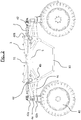
- the rod 62 is fixed on the side frame 10 and the shaft 63 is fixed on the frame as seen in figure 1 .
- the sheath 6b slides, with the help of friction reduction rings such as Teflon rings 611, 612, on the tube 6a which passes through the frame.
- the sleeve 6b is itself received in a cylinder 515 welded 900 to the frame and which forms a reinforcement of the frame.
- the tubes 6a and the sleeves 6b form a telescopic device for adjusting the track of the tractor.
- the tube 6a is of sufficient length to allow a maximum spacing of the frames given by the complete extension of the rod 62 of the jack. In this said position widened way, the end of the tube 6a comes inside the sleeve cantilever relative to the frame.
- the sheath 6b is stepped and comprises a first section 6b1 of a first said upper diameter, a second section 6b2 of intermediate diameter, defining between the first section and this second section a first annular shoulder, a third section 6b3 of reduced diameter and a terminal section 6b4 threaded.
- the third section 6b3 defines between the second section and the third section a second annular abutment shoulder with a shoulder complementary to a cylinder 515 in which is inserted the sleeve, the third section further constituting a bearing for a pair of bearings 803.
- the sleeve is secured to the frame 5 by clamping a nut 518 on an annular wedge 517 also welded 902 on the frame 5.
- the nut is screwed onto the threaded end 6b4 of the sleeve 6b. Both sides of the frame are tightened by the nut 518 due to the presence of annular shoulders between the sheath and the cylinder 515.
- the articulation of the branch 4d which receives the suspension damper 3 is formed on the sheath 6b and in particular on the third section 6b3 forming a bearing surface machined on this sheath.
- This hinge uses a pair of tapered bearings 802, 803, 804 received between the bearing surface 6b3 and an outer welded cage 5203 903 in the branch 4d.
- the bearings are preloaded by means of the nut 518, rings 519 and annular bearing surfaces internal to the outer cage 520 in a conventional manner.
- the Figures 8B and 8C are similar to the figure 8A .
- the Figure 8B shows the position of the frame 5 when the track is reduced, the frame 5 is then close to the frame 20 and the sleeve 6b substantially against the frame, the tube 5a protruding outside the frame. in positions respectively frame retracted, built apart.
- the Figure 8C represents the frame in widened track position. In this position the tube 8a is in the retracted position with respect to the sleeve 6b which has slid outwards under the action of the jack 62, 63. This position is similar to that shown in FIG. figure 1 .
- This assembly that allows to group together in one set the articulation of the upper longitudinal branch 4d of the suspension parallelogram which forms the main oscillating arm of the suspension of the wheels and the fastening of the frames ensures a great rigidity to the whole while making it compact.
- the tractor suspension is deported above the frames 10.
- the suspension is performed by cylinders 3 which hang on the one hand on shafts 51 carried by ears 51 on the top of the beams 5 and on the other hand on pins 401 carried by rods 401 secured to the upper longitudinal branch 4d of the parallelograms as shown in FIG. figure 4 .
- the cylinders act on the parallelograms and the height variations of the tractor are made by the deformation of the parallelograms whose geometry makes it possible to keep the vertical axes 41 of the wheel-bearing legs during the travel of the suspension and the variations in height of the tractor.
- the rod 401 forms a first arm of a lever about the axis 60 carrying the upper connecting arm 4d, which forms the second arm of the lever, to raise and lower the tractor chassis relative to the legs and wheels in the direction B of the figure 1 .
- the cylinders 3 for adjusting the height of the tractor and suspension are hydraulic cylinders for achieving the suspension by compression relaxation around an equilibrium position which defines the height of the tractor.
- the hydraulic circuit of the cylinders is connected to one or more accumulator spheres as shown in FIG. figure 5 .
- each wheel is equipped with a hydraulic motor 75 which is fixed on the legs 7 and whose rotating part is disposed in the hub of the wheel.
- This single linkage system system is very favorable to reduce the overall width of the assembly: the shaft 41 is located above the wheel and the offset leg 7 is connected to said axis and the hub of the wheel.
- the hub of the wheel carries the hydraulic motor 75 and the brake drum 74 while the device of the direction 2 and the suspension devices 3, 4a, 4b, 4c, 4d are offset above the wheel axles.
- leg 7 is hollow and has an opening 71 for passage of the hydraulic hoses of the hydraulic motor and brakes which protects them.
- the axes 41 of the wheel legs are articulated in rotation at one end of the parallelograms to enable the directional wheels to be made.
- the rod 2a and operated by a hydraulic cylinder 2 which has a first end connected to an arm 42 and a second end actuating the link 2a in rotation.
- a finger 72 between stops 73 limits the possibilities of rotation of the legs 7 carrying the wheels.
- the hydraulic circuit of the tractor is partially represented in figure 5 .
- all the wheels are directional which gives great agility to the tractor.
- the tractor comprises a combined suspension / height adjustment made by the cylinders 3 which act as suspension and height adjustment of the tractor.
- the brakes are arranged inside the hub of the wheel and protected by the latter.
- the frames 10 as represented in figure 3 form frames that can receive a storage box or tank 80 for pesticides or other products.
- the figure 5 schematically represents a part of the hydraulic circuit of a tractor according to the invention as regards the height adjustment of the tractor and its direction.
- the forward direction comprises a splitter 200 adapted to control in combination the front steering cylinders 201, 202.
- the rear direction comprises two cylinders 211, 212 acting on the rear wheels in response to the position of the front wheels to make the tractor more manageable .
- the combined suspension / height adjustment device comprises right 301 front left and 302 left front suspension cylinders and right rear 311 and rear left 312 suspension cylinders.
- the damping of the compression suspension is here carried out by means of nitrogen spherical dampers 303, 304. Additional nitrogen spheres 305 common to the two cylinders of an axle provide rebound damping as appropriate. To provide a softer damping additional spheres 306 may be connected to the circuit of the spheres 303 and 304 by means of a splitter or hydraulic block 300 for placing in communication or separation of the circuits of the right and left cylinders of the same axle .
- the device 300 comprises solenoid valves arranged to allow the pressurization of the cylinders, separate, connect, open or close the circuits supplying the spheres 306 according to the function or functions implemented.
- the rear suspension comprises in the same way spheres and a distribution device 310 for connecting or separating the circuits of the right cylinders 311 and left 312 rear.
- All the hydraulic members are connected to a control and distribution circuit 400 which is shown in FIG. figure 7 .
- Each suspension cylinder is controlled from a proportional distributor, distributor 401 for the right front cylinder 301, distributor 402 for the left front cylinder 302, distributor 411 for the right rear cylinder 311 and distributor 412 for the left rear cylinder 312.
- the proportional distributors are controlled by an electronic computer, not shown so as not to overload the diagram, by means of PWM signals in a manner known per se.
- the proportional distributors are supplied with hydraulic pressure by a common power supply unit 420 connected to the hydraulic pumps.
- the parallel control of the distributors will make it possible to carry out height adjustment functions, an anti-roll function and a function of attitude correction by means of sensors such as an accelerometer, an inclinometer and possibly an electronic calculator.
- the computer also controls the dispatching devices 300, 310 according to the operating mode chosen, independent wheels, anti-roll, axle rigid, attitude correction by coupling in the latter case the settings before rear or by making other adjustment according to the configuration of the ground.
- the separate control of the suspension cylinders 301, 302, 311, 312 by dedicated proportional distributors 401, 402, 411, 412 and the presence of distributor devices 300, 310 for separating or placing in communication the cylinders of the same axle allow to adapt the suspension to multiple situations depending on the configuration of the terrain on which the tractor is moving and a high comfort of the operator.
- the figure 6 represents for its part a simplified diagram of hydraulic motors and brakes of a tractor according to the invention.
- the right 501 and left 502 front engines are coupled to drum brakes 503, 504 while the right rear 511 and rear left 512 are equipped with park brakes 513, 514.
- the motors and brakes are controlled by power distribution systems known type and powered by pumps driven by a heat engine.
- the engine can be a diesel engine with a power of 100 to 150 kWh and pump pumps with a cylinder capacity between 50cm 3 and 100cm 3 and capable of delivering a power of 400 bar to 500 bars.
- Hydraulic motors can for example be MSE08 type motors from the company Poclain.
- a hydraulic pump to power the front wheel motors and a hydraulic pump to supply the engines of the rear wheels.
- suspensions can be controlled electronically to vary their stiffness by varying the number of spheres connected to the hydraulic circuit, the spheres being able to be set in or out. switched off by means of solenoid valves.
Landscapes
- Engineering & Computer Science (AREA)
- Mechanical Engineering (AREA)
- Chemical & Material Sciences (AREA)
- Combustion & Propulsion (AREA)
- Transportation (AREA)
- Vehicle Body Suspensions (AREA)
Priority Applications (1)
| Application Number | Priority Date | Filing Date | Title |
|---|---|---|---|
| RS20201110A RS60839B1 (sr) | 2016-11-07 | 2017-11-07 | Traktor visokog klirensa |
Applications Claiming Priority (1)
| Application Number | Priority Date | Filing Date | Title |
|---|---|---|---|
| FR1660730A FR3058380B1 (fr) | 2016-11-07 | 2016-11-07 | Tracteur enjambeur |
Publications (2)
| Publication Number | Publication Date |
|---|---|
| EP3318430A1 true EP3318430A1 (de) | 2018-05-09 |
| EP3318430B1 EP3318430B1 (de) | 2020-06-17 |
Family
ID=57796600
Family Applications (1)
| Application Number | Title | Priority Date | Filing Date |
|---|---|---|---|
| EP17200241.2A Active EP3318430B1 (de) | 2016-11-07 | 2017-11-07 | Stelzentraktor |
Country Status (5)
| Country | Link |
|---|---|
| EP (1) | EP3318430B1 (de) |
| ES (1) | ES2820355T3 (de) |
| FR (1) | FR3058380B1 (de) |
| HU (1) | HUE051539T2 (de) |
| RS (1) | RS60839B1 (de) |
Cited By (7)
| Publication number | Priority date | Publication date | Assignee | Title |
|---|---|---|---|---|
| CN109305242A (zh) * | 2018-10-26 | 2019-02-05 | 辽宁工程技术大学 | 一种两轮双足机器人 |
| WO2019234369A1 (fr) * | 2018-06-08 | 2019-12-12 | Cybelium Technologies | Châssis de véhicule agricole de largeur réglable et véhicule agricole |
| FR3084873A1 (fr) * | 2018-08-08 | 2020-02-14 | Sabi Agri | Tracteur avec porte-roues pivotants |
| WO2020108713A1 (en) * | 2018-11-27 | 2020-06-04 | Agro Intelligence Aps | An agricultural work vehicle |
| US10967695B2 (en) * | 2018-03-02 | 2021-04-06 | Blueline Mfg., Co. | Steerable suspension system |
| US20220015279A1 (en) * | 2018-11-27 | 2022-01-20 | Agro Intelligence Aps | An agricultural work vehicle |
| DE102022115141A1 (de) | 2022-06-16 | 2023-12-21 | Amazonen-Werke H. Dreyer SE & Co. KG | Landwirtschaftliches Fahrzeug |
Citations (6)
| Publication number | Priority date | Publication date | Assignee | Title |
|---|---|---|---|---|
| US6311795B1 (en) * | 2000-05-02 | 2001-11-06 | Case Corporation | Work vehicle steering and suspension system |
| FR2979322A1 (fr) * | 2011-08-26 | 2013-03-01 | Sarl Grosjean Rene Viticole | Vehicule quadricycle enjambeur automoteur |
| US20150102568A1 (en) * | 2013-10-14 | 2015-04-16 | Agco Corporation | Machine suspension and height adjustment |
| US20150291233A1 (en) * | 2014-04-09 | 2015-10-15 | Hagie Manufacturing Company | Variable tread width vehicle |
| EP3025940A1 (de) * | 2014-10-23 | 2016-06-01 | BGroup S.p.A. | Chassis mit variabler spur, insbesondere für landwirtschaftliche maschinen und ausrüstung |
| FR3031069A1 (fr) * | 2014-12-26 | 2016-07-01 | Le Loulay | Vehicule equipe de systemes de correction de devers et de commande de direction pour ensemble roue, et un tel systeme |
-
2016
- 2016-11-07 FR FR1660730A patent/FR3058380B1/fr active Active
-
2017
- 2017-11-07 EP EP17200241.2A patent/EP3318430B1/de active Active
- 2017-11-07 RS RS20201110A patent/RS60839B1/sr unknown
- 2017-11-07 HU HUE17200241A patent/HUE051539T2/hu unknown
- 2017-11-07 ES ES17200241T patent/ES2820355T3/es active Active
Patent Citations (6)
| Publication number | Priority date | Publication date | Assignee | Title |
|---|---|---|---|---|
| US6311795B1 (en) * | 2000-05-02 | 2001-11-06 | Case Corporation | Work vehicle steering and suspension system |
| FR2979322A1 (fr) * | 2011-08-26 | 2013-03-01 | Sarl Grosjean Rene Viticole | Vehicule quadricycle enjambeur automoteur |
| US20150102568A1 (en) * | 2013-10-14 | 2015-04-16 | Agco Corporation | Machine suspension and height adjustment |
| US20150291233A1 (en) * | 2014-04-09 | 2015-10-15 | Hagie Manufacturing Company | Variable tread width vehicle |
| EP3025940A1 (de) * | 2014-10-23 | 2016-06-01 | BGroup S.p.A. | Chassis mit variabler spur, insbesondere für landwirtschaftliche maschinen und ausrüstung |
| FR3031069A1 (fr) * | 2014-12-26 | 2016-07-01 | Le Loulay | Vehicule equipe de systemes de correction de devers et de commande de direction pour ensemble roue, et un tel systeme |
Cited By (9)
| Publication number | Priority date | Publication date | Assignee | Title |
|---|---|---|---|---|
| US10967695B2 (en) * | 2018-03-02 | 2021-04-06 | Blueline Mfg., Co. | Steerable suspension system |
| WO2019234369A1 (fr) * | 2018-06-08 | 2019-12-12 | Cybelium Technologies | Châssis de véhicule agricole de largeur réglable et véhicule agricole |
| FR3082169A1 (fr) * | 2018-06-08 | 2019-12-13 | Cybelium Technologies | Chassis de vehicule agricole de largeur reglable et vehicule agricole |
| FR3084873A1 (fr) * | 2018-08-08 | 2020-02-14 | Sabi Agri | Tracteur avec porte-roues pivotants |
| CN109305242A (zh) * | 2018-10-26 | 2019-02-05 | 辽宁工程技术大学 | 一种两轮双足机器人 |
| CN109305242B (zh) * | 2018-10-26 | 2023-08-25 | 辽宁工程技术大学 | 一种两轮双足机器人 |
| WO2020108713A1 (en) * | 2018-11-27 | 2020-06-04 | Agro Intelligence Aps | An agricultural work vehicle |
| US20220015279A1 (en) * | 2018-11-27 | 2022-01-20 | Agro Intelligence Aps | An agricultural work vehicle |
| DE102022115141A1 (de) | 2022-06-16 | 2023-12-21 | Amazonen-Werke H. Dreyer SE & Co. KG | Landwirtschaftliches Fahrzeug |
Also Published As
| Publication number | Publication date |
|---|---|
| HUE051539T2 (hu) | 2021-03-01 |
| EP3318430B1 (de) | 2020-06-17 |
| FR3058380A1 (fr) | 2018-05-11 |
| ES2820355T3 (es) | 2021-04-20 |
| FR3058380B1 (fr) | 2019-07-19 |
| RS60839B1 (sr) | 2020-10-30 |
Similar Documents
| Publication | Publication Date | Title |
|---|---|---|
| EP3318430B1 (de) | Stelzentraktor | |
| EP1743516B1 (de) | Selbstzentrierende Portalerntekopf für Maschine zum Ernten von kleinen Früchten und Maschine ausgestattet mit einem derartigen Erntekopf | |
| FR2882694A1 (fr) | Dispositif de stabilisation laterale, pour chariot comportant un pont oscillant | |
| FR2739753A1 (fr) | Systeme de suspension et de direction pour pulverisateurs agricoles | |
| FR2993499A1 (fr) | Essieu et vehicule comprenant au moins un tel essieu | |
| EP0328840B1 (de) | Vorrichtung für semi-aktive hydropneumatische Aufhängung und mit dieser Vorrichtung ausgestattetes Kraftfahrzeug | |
| EP3688236B1 (de) | Stabilisierungssystem für ein mit einem lasttragarm ausgestattetes radfahrzeug und mit einem lasttragarm ausgestattetes radfahrzeug mit diesem stabilisierungssystem | |
| EP0997062B1 (de) | Landmaschine | |
| FR2609262A1 (fr) | Installation hydraulique formant palonnier de limitation d'inclinaison transversale d'un train de roulement d'un vehicule et vehicule en faisant application | |
| EP1340670A1 (de) | Unabhängiges Radmodul und ein solches Modul benutzendes Fahrzeug | |
| EP2043902B1 (de) | Reifensatz mit gekoppelten selbstlenkenden achsen für einen sattelauflieger | |
| FR3031069A1 (fr) | Vehicule equipe de systemes de correction de devers et de commande de direction pour ensemble roue, et un tel systeme | |
| FR3049562A1 (fr) | Engin roulant automoteur, notamment pour des travaux d'agriculture | |
| FR2492331A1 (fr) | Remorque, et notamment remorque semi-portee | |
| FR2846931A1 (fr) | Vehicule leger de chantier, notamment vehicule a benne | |
| FR3015915B1 (fr) | Chassis de vehicule omnidirectionnel comportant des corps de chassis deplacables l'un par rapport a l'autre | |
| FR2605966A1 (fr) | Vehicule automoteur destine a deplacer un outil allonge transversal | |
| FR2882500A1 (fr) | Machine de fauchage/debroussaillage et d'elagage comprenant un troisieme essieu a roues independantes | |
| EP1077196B1 (de) | Vorrichtung zum Korrigieren der Schiefstellung für ein zweiachsiges Fahrzeug | |
| EP2143314A1 (de) | Verbesserter oberer Lenker | |
| FR3032595A1 (fr) | Machine de coupe de vegetaux et vehicule automobile comprenant une telle machine de coupe | |
| FR2926492A1 (fr) | Sous ensemble de train roulant de vehicule | |
| FR2765866A1 (fr) | Chariot elevateur de manutention de charges | |
| EP0089910A1 (de) | Selbstfahrendes Geländefahrzeug mit veränderlichem geometrischen Rahmen | |
| EP1670306B1 (de) | Heuerntemaschine mit einer transportaufhängungsvorrichtung |
Legal Events
| Date | Code | Title | Description |
|---|---|---|---|
| PUAI | Public reference made under article 153(3) epc to a published international application that has entered the european phase |
Free format text: ORIGINAL CODE: 0009012 |
|
| STAA | Information on the status of an ep patent application or granted ep patent |
Free format text: STATUS: THE APPLICATION HAS BEEN PUBLISHED |
|
| AK | Designated contracting states |
Kind code of ref document: A1 Designated state(s): AL AT BE BG CH CY CZ DE DK EE ES FI FR GB GR HR HU IE IS IT LI LT LU LV MC MK MT NL NO PL PT RO RS SE SI SK SM TR |
|
| AX | Request for extension of the european patent |
Extension state: BA ME |
|
| STAA | Information on the status of an ep patent application or granted ep patent |
Free format text: STATUS: REQUEST FOR EXAMINATION WAS MADE |
|
| 17P | Request for examination filed |
Effective date: 20181017 |
|
| RBV | Designated contracting states (corrected) |
Designated state(s): AL AT BE BG CH CY CZ DE DK EE ES FI FR GB GR HR HU IE IS IT LI LT LU LV MC MK MT NL NO PL PT RO RS SE SI SK SM TR |
|
| GRAP | Despatch of communication of intention to grant a patent |
Free format text: ORIGINAL CODE: EPIDOSNIGR1 |
|
| STAA | Information on the status of an ep patent application or granted ep patent |
Free format text: STATUS: GRANT OF PATENT IS INTENDED |
|
| RIC1 | Information provided on ipc code assigned before grant |
Ipc: B62D 49/06 20060101ALI20200130BHEP Ipc: B60G 3/12 20060101ALI20200130BHEP Ipc: B60G 3/02 20060101ALI20200130BHEP Ipc: B60G 3/01 20060101AFI20200130BHEP Ipc: B60G 3/20 20060101ALI20200130BHEP |
|
| INTG | Intention to grant announced |
Effective date: 20200218 |
|
| GRAS | Grant fee paid |
Free format text: ORIGINAL CODE: EPIDOSNIGR3 |
|
| GRAA | (expected) grant |
Free format text: ORIGINAL CODE: 0009210 |
|
| STAA | Information on the status of an ep patent application or granted ep patent |
Free format text: STATUS: THE PATENT HAS BEEN GRANTED |
|
| AK | Designated contracting states |
Kind code of ref document: B1 Designated state(s): AL AT BE BG CH CY CZ DE DK EE ES FI FR GB GR HR HU IE IS IT LI LT LU LV MC MK MT NL NO PL PT RO RS SE SI SK SM TR |
|
| REG | Reference to a national code |
Ref country code: GB Ref legal event code: FG4D Free format text: NOT ENGLISH |
|
| REG | Reference to a national code |
Ref country code: CH Ref legal event code: EP |
|
| REG | Reference to a national code |
Ref country code: IE Ref legal event code: FG4D Free format text: LANGUAGE OF EP DOCUMENT: FRENCH |
|
| REG | Reference to a national code |
Ref country code: DE Ref legal event code: R096 Ref document number: 602017018228 Country of ref document: DE |
|
| REG | Reference to a national code |
Ref country code: AT Ref legal event code: REF Ref document number: 1280871 Country of ref document: AT Kind code of ref document: T Effective date: 20200715 |
|
| PG25 | Lapsed in a contracting state [announced via postgrant information from national office to epo] |
Ref country code: SE Free format text: LAPSE BECAUSE OF FAILURE TO SUBMIT A TRANSLATION OF THE DESCRIPTION OR TO PAY THE FEE WITHIN THE PRESCRIBED TIME-LIMIT Effective date: 20200617 Ref country code: NO Free format text: LAPSE BECAUSE OF FAILURE TO SUBMIT A TRANSLATION OF THE DESCRIPTION OR TO PAY THE FEE WITHIN THE PRESCRIBED TIME-LIMIT Effective date: 20200917 Ref country code: FI Free format text: LAPSE BECAUSE OF FAILURE TO SUBMIT A TRANSLATION OF THE DESCRIPTION OR TO PAY THE FEE WITHIN THE PRESCRIBED TIME-LIMIT Effective date: 20200617 Ref country code: LT Free format text: LAPSE BECAUSE OF FAILURE TO SUBMIT A TRANSLATION OF THE DESCRIPTION OR TO PAY THE FEE WITHIN THE PRESCRIBED TIME-LIMIT Effective date: 20200617 |
|
| REG | Reference to a national code |
Ref country code: LT Ref legal event code: MG4D |
|
| REG | Reference to a national code |
Ref country code: NL Ref legal event code: MP Effective date: 20200617 |
|
| PG25 | Lapsed in a contracting state [announced via postgrant information from national office to epo] |
Ref country code: LV Free format text: LAPSE BECAUSE OF FAILURE TO SUBMIT A TRANSLATION OF THE DESCRIPTION OR TO PAY THE FEE WITHIN THE PRESCRIBED TIME-LIMIT Effective date: 20200617 Ref country code: HR Free format text: LAPSE BECAUSE OF FAILURE TO SUBMIT A TRANSLATION OF THE DESCRIPTION OR TO PAY THE FEE WITHIN THE PRESCRIBED TIME-LIMIT Effective date: 20200617 Ref country code: BG Free format text: LAPSE BECAUSE OF FAILURE TO SUBMIT A TRANSLATION OF THE DESCRIPTION OR TO PAY THE FEE WITHIN THE PRESCRIBED TIME-LIMIT Effective date: 20200917 |
|
| PG25 | Lapsed in a contracting state [announced via postgrant information from national office to epo] |
Ref country code: NL Free format text: LAPSE BECAUSE OF FAILURE TO SUBMIT A TRANSLATION OF THE DESCRIPTION OR TO PAY THE FEE WITHIN THE PRESCRIBED TIME-LIMIT Effective date: 20200617 Ref country code: AL Free format text: LAPSE BECAUSE OF FAILURE TO SUBMIT A TRANSLATION OF THE DESCRIPTION OR TO PAY THE FEE WITHIN THE PRESCRIBED TIME-LIMIT Effective date: 20200617 |
|
| PG25 | Lapsed in a contracting state [announced via postgrant information from national office to epo] |
Ref country code: SM Free format text: LAPSE BECAUSE OF FAILURE TO SUBMIT A TRANSLATION OF THE DESCRIPTION OR TO PAY THE FEE WITHIN THE PRESCRIBED TIME-LIMIT Effective date: 20200617 Ref country code: PT Free format text: LAPSE BECAUSE OF FAILURE TO SUBMIT A TRANSLATION OF THE DESCRIPTION OR TO PAY THE FEE WITHIN THE PRESCRIBED TIME-LIMIT Effective date: 20201019 Ref country code: CZ Free format text: LAPSE BECAUSE OF FAILURE TO SUBMIT A TRANSLATION OF THE DESCRIPTION OR TO PAY THE FEE WITHIN THE PRESCRIBED TIME-LIMIT Effective date: 20200617 Ref country code: EE Free format text: LAPSE BECAUSE OF FAILURE TO SUBMIT A TRANSLATION OF THE DESCRIPTION OR TO PAY THE FEE WITHIN THE PRESCRIBED TIME-LIMIT Effective date: 20200617 |
|
| PG25 | Lapsed in a contracting state [announced via postgrant information from national office to epo] |
Ref country code: PL Free format text: LAPSE BECAUSE OF FAILURE TO SUBMIT A TRANSLATION OF THE DESCRIPTION OR TO PAY THE FEE WITHIN THE PRESCRIBED TIME-LIMIT Effective date: 20200617 Ref country code: SK Free format text: LAPSE BECAUSE OF FAILURE TO SUBMIT A TRANSLATION OF THE DESCRIPTION OR TO PAY THE FEE WITHIN THE PRESCRIBED TIME-LIMIT Effective date: 20200617 Ref country code: IS Free format text: LAPSE BECAUSE OF FAILURE TO SUBMIT A TRANSLATION OF THE DESCRIPTION OR TO PAY THE FEE WITHIN THE PRESCRIBED TIME-LIMIT Effective date: 20201017 |
|
| REG | Reference to a national code |
Ref country code: HU Ref legal event code: AG4A Ref document number: E051539 Country of ref document: HU |
|
| REG | Reference to a national code |
Ref country code: DE Ref legal event code: R097 Ref document number: 602017018228 Country of ref document: DE |
|
| REG | Reference to a national code |
Ref country code: ES Ref legal event code: FG2A Ref document number: 2820355 Country of ref document: ES Kind code of ref document: T3 Effective date: 20210420 |
|
| PLBE | No opposition filed within time limit |
Free format text: ORIGINAL CODE: 0009261 |
|
| STAA | Information on the status of an ep patent application or granted ep patent |
Free format text: STATUS: NO OPPOSITION FILED WITHIN TIME LIMIT |
|
| PG25 | Lapsed in a contracting state [announced via postgrant information from national office to epo] |
Ref country code: DK Free format text: LAPSE BECAUSE OF FAILURE TO SUBMIT A TRANSLATION OF THE DESCRIPTION OR TO PAY THE FEE WITHIN THE PRESCRIBED TIME-LIMIT Effective date: 20200617 |
|
| 26N | No opposition filed |
Effective date: 20210318 |
|
| PG25 | Lapsed in a contracting state [announced via postgrant information from national office to epo] |
Ref country code: SI Free format text: LAPSE BECAUSE OF FAILURE TO SUBMIT A TRANSLATION OF THE DESCRIPTION OR TO PAY THE FEE WITHIN THE PRESCRIBED TIME-LIMIT Effective date: 20200617 |
|
| REG | Reference to a national code |
Ref country code: AT Ref legal event code: UEP Ref document number: 1280871 Country of ref document: AT Kind code of ref document: T Effective date: 20200617 |
|
| PG25 | Lapsed in a contracting state [announced via postgrant information from national office to epo] |
Ref country code: MC Free format text: LAPSE BECAUSE OF FAILURE TO SUBMIT A TRANSLATION OF THE DESCRIPTION OR TO PAY THE FEE WITHIN THE PRESCRIBED TIME-LIMIT Effective date: 20200617 |
|
| REG | Reference to a national code |
Ref country code: CH Ref legal event code: PL |
|
| PG25 | Lapsed in a contracting state [announced via postgrant information from national office to epo] |
Ref country code: LU Free format text: LAPSE BECAUSE OF NON-PAYMENT OF DUE FEES Effective date: 20201107 |
|
| REG | Reference to a national code |
Ref country code: BE Ref legal event code: MM Effective date: 20201130 |
|
| PG25 | Lapsed in a contracting state [announced via postgrant information from national office to epo] |
Ref country code: LI Free format text: LAPSE BECAUSE OF NON-PAYMENT OF DUE FEES Effective date: 20201130 Ref country code: CH Free format text: LAPSE BECAUSE OF NON-PAYMENT OF DUE FEES Effective date: 20201130 |
|
| PG25 | Lapsed in a contracting state [announced via postgrant information from national office to epo] |
Ref country code: IE Free format text: LAPSE BECAUSE OF NON-PAYMENT OF DUE FEES Effective date: 20201107 |
|
| PG25 | Lapsed in a contracting state [announced via postgrant information from national office to epo] |
Ref country code: TR Free format text: LAPSE BECAUSE OF FAILURE TO SUBMIT A TRANSLATION OF THE DESCRIPTION OR TO PAY THE FEE WITHIN THE PRESCRIBED TIME-LIMIT Effective date: 20200617 Ref country code: MT Free format text: LAPSE BECAUSE OF FAILURE TO SUBMIT A TRANSLATION OF THE DESCRIPTION OR TO PAY THE FEE WITHIN THE PRESCRIBED TIME-LIMIT Effective date: 20200617 Ref country code: CY Free format text: LAPSE BECAUSE OF FAILURE TO SUBMIT A TRANSLATION OF THE DESCRIPTION OR TO PAY THE FEE WITHIN THE PRESCRIBED TIME-LIMIT Effective date: 20200617 |
|
| PG25 | Lapsed in a contracting state [announced via postgrant information from national office to epo] |
Ref country code: MK Free format text: LAPSE BECAUSE OF FAILURE TO SUBMIT A TRANSLATION OF THE DESCRIPTION OR TO PAY THE FEE WITHIN THE PRESCRIBED TIME-LIMIT Effective date: 20200617 |
|
| GBPC | Gb: european patent ceased through non-payment of renewal fee |
Effective date: 20211107 |
|
| PG25 | Lapsed in a contracting state [announced via postgrant information from national office to epo] |
Ref country code: GR Free format text: LAPSE BECAUSE OF FAILURE TO SUBMIT A TRANSLATION OF THE DESCRIPTION OR TO PAY THE FEE WITHIN THE PRESCRIBED TIME-LIMIT Effective date: 20200617 Ref country code: BE Free format text: LAPSE BECAUSE OF NON-PAYMENT OF DUE FEES Effective date: 20201130 |
|
| PG25 | Lapsed in a contracting state [announced via postgrant information from national office to epo] |
Ref country code: GB Free format text: LAPSE BECAUSE OF NON-PAYMENT OF DUE FEES Effective date: 20211107 |
|
| PGFP | Annual fee paid to national office [announced via postgrant information from national office to epo] |
Ref country code: ES Payment date: 20231219 Year of fee payment: 7 |
|
| PGFP | Annual fee paid to national office [announced via postgrant information from national office to epo] |
Ref country code: RS Payment date: 20231102 Year of fee payment: 7 Ref country code: RO Payment date: 20231031 Year of fee payment: 7 Ref country code: IT Payment date: 20231121 Year of fee payment: 7 Ref country code: HU Payment date: 20231025 Year of fee payment: 7 Ref country code: FR Payment date: 20231123 Year of fee payment: 7 Ref country code: DE Payment date: 20231121 Year of fee payment: 7 Ref country code: AT Payment date: 20231122 Year of fee payment: 7 |