EP3688236B1 - Stabilisierungssystem für ein mit einem lasttragarm ausgestattetes radfahrzeug und mit einem lasttragarm ausgestattetes radfahrzeug mit diesem stabilisierungssystem - Google Patents
Stabilisierungssystem für ein mit einem lasttragarm ausgestattetes radfahrzeug und mit einem lasttragarm ausgestattetes radfahrzeug mit diesem stabilisierungssystem Download PDFInfo
- Publication number
- EP3688236B1 EP3688236B1 EP18774052.7A EP18774052A EP3688236B1 EP 3688236 B1 EP3688236 B1 EP 3688236B1 EP 18774052 A EP18774052 A EP 18774052A EP 3688236 B1 EP3688236 B1 EP 3688236B1
- Authority
- EP
- European Patent Office
- Prior art keywords
- arm
- machine
- cylinder
- spool
- distributor
- Prior art date
- Legal status (The legal status is an assumption and is not a legal conclusion. Google has not performed a legal analysis and makes no representation as to the accuracy of the status listed.)
- Active
Links
- 230000006641 stabilisation Effects 0.000 title claims description 33
- 238000011105 stabilization Methods 0.000 claims description 32
- 239000012530 fluid Substances 0.000 claims description 29
- 238000004891 communication Methods 0.000 claims description 19
- 238000012550 audit Methods 0.000 description 4
- 230000000750 progressive effect Effects 0.000 description 3
- 244000025254 Cannabis sativa Species 0.000 description 2
- 230000014509 gene expression Effects 0.000 description 2
- 238000005259 measurement Methods 0.000 description 2
- 230000001447 compensatory effect Effects 0.000 description 1
- 230000000694 effects Effects 0.000 description 1
- 238000012423 maintenance Methods 0.000 description 1
- 238000000034 method Methods 0.000 description 1
- 230000007935 neutral effect Effects 0.000 description 1
- 238000011084 recovery Methods 0.000 description 1
- 238000009966 trimming Methods 0.000 description 1
- 239000002023 wood Substances 0.000 description 1
Images


Classifications
-
- E—FIXED CONSTRUCTIONS
- E02—HYDRAULIC ENGINEERING; FOUNDATIONS; SOIL SHIFTING
- E02F—DREDGING; SOIL-SHIFTING
- E02F9/00—Component parts of dredgers or soil-shifting machines, not restricted to one of the kinds covered by groups E02F3/00 - E02F7/00
- E02F9/02—Travelling-gear, e.g. associated with slewing gears
- E02F9/028—Travelling-gear, e.g. associated with slewing gears with arrangements for levelling the machine
-
- B—PERFORMING OPERATIONS; TRANSPORTING
- B60—VEHICLES IN GENERAL
- B60G—VEHICLE SUSPENSION ARRANGEMENTS
- B60G17/00—Resilient suspensions having means for adjusting the spring or vibration-damper characteristics, for regulating the distance between a supporting surface and a sprung part of vehicle or for locking suspension during use to meet varying vehicular or surface conditions, e.g. due to speed or load
- B60G17/015—Resilient suspensions having means for adjusting the spring or vibration-damper characteristics, for regulating the distance between a supporting surface and a sprung part of vehicle or for locking suspension during use to meet varying vehicular or surface conditions, e.g. due to speed or load the regulating means comprising electric or electronic elements
- B60G17/016—Resilient suspensions having means for adjusting the spring or vibration-damper characteristics, for regulating the distance between a supporting surface and a sprung part of vehicle or for locking suspension during use to meet varying vehicular or surface conditions, e.g. due to speed or load the regulating means comprising electric or electronic elements characterised by their responsiveness, when the vehicle is travelling, to specific motion, a specific condition, or driver input
- B60G17/0165—Resilient suspensions having means for adjusting the spring or vibration-damper characteristics, for regulating the distance between a supporting surface and a sprung part of vehicle or for locking suspension during use to meet varying vehicular or surface conditions, e.g. due to speed or load the regulating means comprising electric or electronic elements characterised by their responsiveness, when the vehicle is travelling, to specific motion, a specific condition, or driver input to an external condition, e.g. rough road surface, side wind
-
- B—PERFORMING OPERATIONS; TRANSPORTING
- B60—VEHICLES IN GENERAL
- B60G—VEHICLE SUSPENSION ARRANGEMENTS
- B60G9/00—Resilient suspensions of a rigid axle or axle housing for two or more wheels
- B60G9/02—Resilient suspensions of a rigid axle or axle housing for two or more wheels the axle or housing being pivotally mounted on the vehicle, e.g. the pivotal axis being parallel to the longitudinal axis of the vehicle
-
- E—FIXED CONSTRUCTIONS
- E02—HYDRAULIC ENGINEERING; FOUNDATIONS; SOIL SHIFTING
- E02F—DREDGING; SOIL-SHIFTING
- E02F9/00—Component parts of dredgers or soil-shifting machines, not restricted to one of the kinds covered by groups E02F3/00 - E02F7/00
- E02F9/20—Drives; Control devices
- E02F9/22—Hydraulic or pneumatic drives
- E02F9/2257—Vehicle levelling or suspension systems
-
- A—HUMAN NECESSITIES
- A01—AGRICULTURE; FORESTRY; ANIMAL HUSBANDRY; HUNTING; TRAPPING; FISHING
- A01B—SOIL WORKING IN AGRICULTURE OR FORESTRY; PARTS, DETAILS, OR ACCESSORIES OF AGRICULTURAL MACHINES OR IMPLEMENTS, IN GENERAL
- A01B51/00—Undercarriages specially adapted for mounting-on various kinds of agricultural tools or apparatus
-
- A—HUMAN NECESSITIES
- A01—AGRICULTURE; FORESTRY; ANIMAL HUSBANDRY; HUNTING; TRAPPING; FISHING
- A01B—SOIL WORKING IN AGRICULTURE OR FORESTRY; PARTS, DETAILS, OR ACCESSORIES OF AGRICULTURAL MACHINES OR IMPLEMENTS, IN GENERAL
- A01B76/00—Parts, details or accessories of agricultural machines or implements, not provided for in groups A01B51/00 - A01B75/00
-
- A—HUMAN NECESSITIES
- A01—AGRICULTURE; FORESTRY; ANIMAL HUSBANDRY; HUNTING; TRAPPING; FISHING
- A01D—HARVESTING; MOWING
- A01D34/00—Mowers; Mowing apparatus of harvesters
- A01D34/835—Mowers; Mowing apparatus of harvesters specially adapted for particular purposes
- A01D34/86—Mowers; Mowing apparatus of harvesters specially adapted for particular purposes for use on sloping ground, e.g. on embankments or in ditches
-
- A—HUMAN NECESSITIES
- A01—AGRICULTURE; FORESTRY; ANIMAL HUSBANDRY; HUNTING; TRAPPING; FISHING
- A01D—HARVESTING; MOWING
- A01D42/00—Mowers convertible to apparatus for purposes other than mowing; Mowers capable of performing operations other than mowing
Definitions
- the present invention relates to a stabilization system for a wheeled vehicle equipped with a load carrying arm, and the wheeled vehicle equipped with a load carrying arm, including this stabilization system.
- This machine can be any type of machine equipped with an arm carrying a load or intended to carry a load, this arm being capable of being placed in a position of lateral extension with respect to the machine.
- This extension is such that it is likely to generate a tipping moment that could risk causing the vehicle to overturn, or at least to raise a wheel of the machine, causing instability of the machine along a line. passing through this wheel and through the diagonally opposite wheel.
- the machine can in particular be a trimming machine, that is to say a machine for cutting coppices or mowing grass on an embankment along a traffic lane; the load carried by the arm is then the cutting or mowing tool.
- a trimming machine that is to say a machine for cutting coppices or mowing grass on an embankment along a traffic lane; the load carried by the arm is then the cutting or mowing tool.
- a wheeled machine equipped with a load-carrying arm can, in certain situations, be unbalanced to the point of risk of overturning, due to the load carried by the arm and the offset of this arm in relation to the machine. , and in particular when crossing a terrain accident leading to raising a wheel of the machine located on the side opposite to the side on which the arm extends.
- the object of the present invention is therefore to remedy this shortcoming.
- crutches It is certainly known to stabilize a machine by means of crutches; however, these crutches can only be used statically, while the machine is stationary, and are therefore not suitable for a machine having to move forward on a terrain or a traffic lane for the accomplishment of the required work. In addition, these crutches cannot be used on possibly uneven or loose ground, as can be the case with wood log handling equipment working in the forest.
- the documents FR 1 406 770 A , US 5,180,028 A and US 5,639,119 A disclose various systems in accordance with the prior art, which do not make it possible to fill the aforementioned gap.
- the preamble of the independent claim is based on the content of the document FR 1 406 770 A .
- the stabilization system concerned is therefore intended to equip a wheeled machine including a load-carrying arm, the machine comprising a frame, hereinafter referred to as “main frame”, on which at least one wheel-carrying axle is mounted oscillating around. a bearing; a jack, hereinafter referred to as “boom jack”, is associated with the load carrying arm to adjust the inclination of this arm relative to this main frame.
- upper chamber and “lower chamber” of one or the other of said jacks, it is designated the parts of the chamber of the jack which are situated on either side of the piston of this cylinder.
- the upper chamber is that which is furthest from the ground when the machine is placed on the ground, and vice versa with regard to the lower chamber.
- proportional distributor is meant a distributor whose slide comprises ducts machined at a bevel so that the movement of the slide produces a progressive variation of the flow rate of control fluid from the jacks through this slide; such a distributor is known per se.
- the distributor spool In the absence of axle tilt, the distributor spool is held in said first position, in which the actuator control fluid circulates freely through the distributor spool, so that the compensating cylinders do not have no action on the axle; the lower chamber of the boom cylinder is supplied by an independent source of fluid, in order to control the inclination of the arm adequately according to the work to be carried out.
- the inclination sensor transmits the information of this inclination to the computer and the computer controls said actuating means of the distributor so as to progressively move the spool of this distributor from said first position to said second position, according to the degree of inclination detected;
- the pressurized fluid contained in the lower chamber of the boom cylinder is then supplied under pressure, through the distributor, to the upper chamber of the first compensation cylinder and to the lower chamber of the second compensation cylinder, thus causing these jacks to exert a torque on the axle tending to return the axle to a position in which the raised wheel is brought into contact with the ground, thus eliminating the instability of the machine along the diagonal going from this wheel raised to the opposite wheel located on the other axle of the machine; the escape of the fluid out of the lower chamber of the boom cylinder leads to a retraction of the rod of this
- the return of the axle to a non-tilting position causes the computer to control said actuating means so as to gradually return the valve spool to said first position.
- the invention consequently provides a stabilization system making it possible to process in real time the risk of the vehicle overturning by a compensatory action on the inclination of the axle; this treatment is implemented regardless of the type of work to be accomplished and the types of tools likely to be mounted on the arm, and thus makes the machine equipped with this completely versatile system.
- the arm In practice, once the arm and / or the load (in particular a tool) in place on the machine, the arm is deployed to the maximum while the machine is flat and then is actuated so as to lift the load, which results in putting the fluid of the boom cylinder under pressure and which causes one of the wheels of the machine to rise from the ground; the computer's self-learning function is then activated and the distributor is controlled by the computer so as to progressively supply the compensation cylinders in order to bring the raised wheel back into contact with the ground; when this state of re-stabilization of the machine on its wheels is reached, said second and third sensors detect the fluid pressure that it is necessary to feed into the compensation cylinders to obtain this state, and this specific pressure value, adapted to the specific type of arm used, and / or adapted to the mass of the load carried by the arm, is recorded by the computer.
- This specific pressure value is then used as the maximum setpoint value by the computer to control the proportional distributor so as to achieve the axle tilt compensation adapted to the specific type of arm or to the mass of the load carried by the arm.
- the computer will control the coils of the distributor to supply the compensation cylinders with a view to reaching a pressure proportional to the pressure of the boom cylinder.
- the calculator will maintain this proportion by establishing a real-time copy.
- the machine equipped with the stabilization system thus designed is therefore suitable for receiving various types of interchangeable arms, having their own boom cylinders, and / or loads having different masses, and the stabilization system is suitable for s' auto-calibrate to the pressure that exists in the boom cylinder specific to the arm being used when the load is lifted.
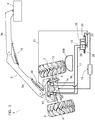
- the figures 1 to 3 represent a machine 1 with rear wheels 2, comprising an arm 3 capable of carrying a load 4.
- This load 4 can be of any type; it may in particular be a tool for cutting coppice or mowing the grass present on an embankment along a traffic lane.
- the machine 1 comprises a frame 5, hereinafter referred to as "main frame”, on which an axle 6 carrying the two wheels 2 is mounted oscillating around a bearing 7.
- This frame 5 also carries a front axle carrying two wheels. front, not visible in the figures.
- the machine 1 is equipped with a stabilization system comprising an oscillating frame 10, a first cylinder 11, a second cylinder 12, a proportional distributor 13, a detector 14 for tilting the axle 6 and a computer 15.
- a stabilization system comprising an oscillating frame 10, a first cylinder 11, a second cylinder 12, a proportional distributor 13, a detector 14 for tilting the axle 6 and a computer 15.
- the oscillating frame 10 has, in a direction transverse to the longitudinal axis of the vehicle 1, a dimension such that it is suitable for being connected to the axle 6 at two points of connection to this axle located on either side. the other of the bearing 7, at a distance from this bearing and located symmetrically with respect to the axis of this bearing.
- this oscillating frame 10 causes this frame to oscillate with this axle in the event of an encounter with a terrain accident as designated by the reference 100 in the figures.
- connection points is pivotally connected to the piston rod of the first cylinder 11 and the body of this first cylinder 11 is pivotally connected to the main frame 5; the other of these connection points is pivotally connected to the rod piston of the second cylinder 12 and the body of this second cylinder 12 is also pivotally connected to the main frame 5.
- These cylinders 11, 12 are hereinafter referred to as “compensation cylinders”, in the sense that they make it possible to " compensate "for the inclination of the axle 6 to bring back the wheel 2 opposite the arm in contact with the ground when this wheel is raised above the ground on the occasion of the crossing of the terrain accident 100, this resulting heightening the combination of this crossing, the offset of the arm 3 and the mass of the load 4.
- the upper chambers and the lower chambers of the compensation cylinders 11, 12 are connected to the distributor 13, on the same first side of the slide of this distributor; the upper chamber of the cylinder 11 and the lower chamber of the cylinder 12 are connected to an orifice of this drawer by a pipe 16, while the lower chamber of the cylinder 11 and the upper chamber of the cylinder 12 are connected to another orifice of this drawer , by a pipe 17.
- the arm 3 includes a base pivotally mounted on an upper wall of the oscillating frame 10; in the embodiment shown on the figures 1 to 3 , this base pivots over a maximum sector of 90 ° relative to the oscillating frame 10, on either side of a median lateral position, so that the arm 3 always remains on the same lateral side of the vehicle 1 (the right side of this machine as shown in these figures) or that it can be positioned in the longitudinal axis of machine 1.
- This arm 3 has, also in this exemplary embodiment, an arrow 3a pivotally connected to said base of the arm, and a free end part 3b able to receive the load 4.
- This free end part 3b is connected to pivotally to the boom 3a and is able to be actuated relative to the latter by means of a jack 18.
- a jack 20 hereinafter referred to as "boom jack"
- the lower chamber of which is connected to the distributor 13 by a pipe 21, in an orifice located on a second side of the drawer of this dispenser, opposite to said first side.
- Another orifice of this slide, on this second side is connected to a reservoir 22 of fluid for actuating the jacks 11 and 12.
- the lower chamber of the jack 20 is also connected to an independent source of actuating fluid, making it possible to carry out, in combination with the jack 18, the deployment of the arm 3.
- the distributor 13 is of a known type, in particular that marketed by the company Fluid System under the reference 2149-90-A.
- Its drawer comprises a first box 25 which, in a first position of the drawer shown on the figure 1 , exhausts the upper and lower chambers of the cylinders 11, 12 and puts the lower chamber of the boom cylinder 20 in fluid flow stop;
- the drawer comprises a second box 26 which, in the second position of the drawer visible on the figure 2 , puts the upper chamber of the cylinder 11 and the lower chamber of the cylinder 12 in communication with the lower chamber of the cylinder 20, and simultaneously puts the lower chamber of the cylinder 11 and the upper chamber of the cylinder 12 to the exhaust.
- proportional for this distributor 13 means that the spool comprises ducts machined at a bevel so that the movement of the spool produces a progressive variation in the flow of control fluid from the jacks 11, 12 through this spool.
- the spool of the distributor 13 is slidably biased, on the side of the box 25, by a spring 28 and, on the side of the box 26 by a proportional coil 30 connected to the computer 15 and controlled by the latter as a function of the angle d tilt of axle 6 detected by detector 14.
- This qualifier of "proportional" for this coil 30 means that the coil controls the movement of the spool gradually, according to the control instructions provided by the computer 15, these instructions themselves being a function of the degree of inclination of the axle. 6.
- the detector 14 is also of a known type; it is able to measure the pivot angle of the axle 6 with respect to the bearing 7, therefore the inclination of this axle.
- the computer 15 which is for example that marketed under the Danfoss brand and reference MC50-010, is connected to the detector 14 and to the coil 30; it is programmed to take into account the inclination measurement of axle 6 when this inclination leads to an elevation of the wheel 2 located opposite the arm 3, a situation visible on the figure 2 , and to act on the coil 30 so as to progressively move the spool of the distributor 13 from said first position visible on the figure 1 towards said second position visible on the figure 2 depending on the tilt detected.
- the computer 15 is also programmed not to take into account the inclination measurement of axle 6 when this inclination of the axle leads to an elevation of the wheel 2 located on the side of the arm 3, a situation visible on the figure 3 , of so that the distributor spool 13, in this situation, remains in the position shown on this figure 3 .
- the sensor 14 transmits the information of this inclination to the computer 15 and the computer controls the coil 30 so as to move the spool of the distributor 13 from said first position to said second position, according to the degree of inclination detected; the pressurized fluid contained in the lower chamber of the boom cylinder 20 is then supplied under pressure, through the distributor 13, to the upper chamber of the cylinder 11 and to the lower chamber of the cylinder 12, thus causing these cylinders to exert on the 'axle 6 a couple tending to compensate for the inclination of the axle 6 in order to bring the wheel 2 back into contact with the ground, and thus eliminate the instability of the machine 1 along the diagonal going from this wheel 2 to the front wheel located on the opposite side of the machine, and therefore simultaneously balancing the oscillating frame 10 with respect to the
- the return of the axle 6 to a non-tilting position causes the computer 15 to control the coil 30 so as to stop acting on the spool against the spring 28, allowing this spring 28 to return the spool of the distributor 13 to said first position.
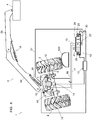
- the figure 4 shows a stabilization system according to a second embodiment, in which most of the elements already described are found in an identical or similar manner. For simplicity, these elements already described which are found in this second embodiment are designated by the same numerical references and are not described again.
- the arm 3 is pivoting on a sector such that it can be brought to one or the other of the lateral sides of the machine 1.
- the stabilization system then comprises a sensor 40 connected to the computer 15, for detecting the angular position of the arm 3 relative to the vehicle 1, therefore making it possible to determine on which lateral side of the vehicle 1 the arm 3 is located.
- the dispenser drawer 13 comprises a third box 41, located, relative to box 25, on the side of the drawer opposite to that on which box 26 is located, allowing the compensation cylinders 11, 12 to be placed in communication with the chamber. lower of the boom cylinder 20 and with the fluid reservoir 22 which are reversed with respect to the communications that the second box 26 allows.
- the spool 13 is associated with a proportional coil 42 identical to the coil 30, located on the side of the spool opposite to that on which this coil 30 acts, and acting antagonistically to the latter. It is also associated with two springs 28, one on each side of the slide 13, so as to return this slide to its central position if no coil 30, 42 is supplied; the distributor 13 can thus be controlled by the computer 15 between the three possible positions of the spool 13.
- box 26 is placed in the active position when arm 3 is on a first lateral side of machine 1 (the right side of this machine, as shown in this figure 5 ); the figure 6 shows that the third box 41 is on the other hand placed in the active position when the arm 3 is on the second lateral side of the machine 1 (on the left of the machine as shown in figure figure 6 ), opposite the first side.
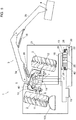
- FIG 7 shows a stabilization system according to another embodiment, in which most of the elements already described are also found in an identical or similar manner and are designated by the same reference numerals as previously.
- the machine 1 is designed so that the arm 3 is interchangeable, so that the machine can be adapted to different types of work, the interchange being made by removing an arm 3 from the swivel base and assembly of another arm 3.
- This interchange causes the boom cylinder 20 associated with each arm to be different in terms of chamber volume and working pressure.
- the machine 1 is designed so that the load 4 is interchangeable with respect to the arm 3, for example a tool of a first type being interchangeable with one or more tools of another type, not having not the same mass as the other tools, or the load may vary during the use of the machine, for example when transporting logs in the forest.
- the stabilization system then comprises a first pressure sensor 50, present on the pipe 21 connecting the boom cylinder 20 of the arm 3 used to the distributor 13, a second pressure sensor 51, present on the pipe 16 connecting the compensation cylinders 11, 12 to the distributor 13, and a third pressure sensor 52, present on the pipe 17 connecting the compensation cylinders 11, 12 to the distributor 13, these various sensors being connected to the computer 15.
- the computer 15 includes a self-learning function AP making it possible to establish a setpoint pressure value, necessary to stabilize the machine as a function of the type of arm 3 mounted on the machine, and therefore as a function of the type of jack arrow 20 which equips this arm, or depending on the load 4 carried by the arm.
- the arm 3 and / or the load 4 in place on the machine 1 the arm 3 is deployed to the maximum while the machine 1 is flat and then is actuated. so as to lift the load 4, which results in putting the fluid of the boom cylinder 20 under pressure and which causes one of the wheels 2 of the machine to rise from the ground; the self-learning function AP of the computer 15 is then activated and the distributor 13 is controlled by the computer so as to progressively supply the compensation cylinders 11, 12 in order to bring the raised wheel 2 back into contact with the ground; when this state of re-stabilization of the machine 1 on its wheels 2 is reached, said second and third sensors 51, 52 detect the fluid pressure that it is necessary to feed into the compensation cylinders 11, 12 to obtain this state, and this specific pressure value, adapted to the specific type of arm 3 used, and / or adapted to the mass of the load 4 carried by the arm, is recorded by the computer 15.
- This specific pressure value is then used as the maximum setpoint value by the computer 15 to control the proportional distributor 13 so as to achieve the tilt compensation of the axle 6 adapted to the specific type of arm 3 or to the mass of the load 4 carried by the arm 3.
- the computer 15 will control the coils of the distributor 30, 42 to supply the compensation cylinders 11, 12 with a view to reaching a pressure proportional to the pressure of the boom cylinder 20.
- the computer 15 will maintain this proportion by establishing issuing a copy in real time.
- the machine 1 equipped with the stabilization system thus designed is therefore able to receive various types of interchangeable arms 3, having jib cylinders 20 specific to them, and / or loads 4 having different masses, and the stabilization system is able to self-calibrate as a function of the pressure which exists in the boom cylinder 20 of the arm 3 used, when the load 4 is lifted.
Landscapes
- Engineering & Computer Science (AREA)
- Mining & Mineral Resources (AREA)
- Civil Engineering (AREA)
- General Engineering & Computer Science (AREA)
- Structural Engineering (AREA)
- Mechanical Engineering (AREA)
- Forklifts And Lifting Vehicles (AREA)
- Vehicle Body Suspensions (AREA)
- Operation Control Of Excavators (AREA)
Claims (4)
- Stabilisierungssystem für eine Maschine (1) mit Rädern (2), die mit einem Lastarm (3) ausgestattet ist, wobei die Maschine (1) ein Chassis (5), im Folgenden "Hauptchassis" genannt, umfasst, auf dem mindestens eine Achse (6), die die Räder (2) trägt, um ein Lager (7) schwenkbar montiert ist; ein Stellglied (20), im Folgenden "Auslegerstellglied" genannt, ist dem Lastarm (3) zugeordnet, um die Neigung dieses Arms in Bezug auf das Hauptchassis (5) zu regulieren;
wobei das Stabilisierungssystem Folgendes umfasst- einen Schwingrahmen (10), der mit der Achse (6) an zwei Verbindungspunkten verbunden werden kann, die sich in einem Abstand von dem Lager (7) beiderseits dieses Lagers (7) und symmetrisch zu dessen Achse befinden; diese Verbindung dieses Schwingrahmens (10) mit der Achse (6) bewirkt, dass dieser Rahmen mit der Achse (6) schwingt; der Tragarm (3) ist dazu bestimmt, an diesem Schwingrahmen (10) angebracht zu werden;- zwei Zylinder (11, 12), im Folgenden als "Ausgleichszylinder" bezeichnet, von denen einer einen ersten der Verbindungspunkte mit dem Hauptrahmen (5) und der andere den zweiten der Verbindungspunkte mit dem Hauptrahmen (5) verbindet; ein erster dieser Ausgleichszylinder (11) befindet sich gegenüber dem Arm (3) und der zweite dieser Ausgleichszylinder (12) befindet sich auf der Seite des Arms (3);- einen Proportionalverteiler (13); die obere Kammer des ersten Ausgleichszylinders (11) und die untere Kammer des zweiten Ausgleichszylinders (12) sind über eine gleiche erste Leitung (16) mit einer Öffnung verbunden, die sich auf einer ersten Seite des Steuerkolbens dieses Verteilers (13) befindet, während die untere Kammer des ersten Ausgleichszylinders (11) und die obere Kammer des zweiten Ausgleichszylinders (12) über eine gleiche zweite Leitung (17) mit einer weiteren Öffnung verbunden sind, die sich auf der ersten Seite des Steuerkolbens dieses Verteilers (13) befindet; die untere Kammer des Auslegerzylinders (20) mit einem Anschluss auf einer zweiten Seite des Steuerkolbens des Schieberventils (13) verbunden ist, die der ersten Seite gegenüberliegt, und ein weiterer Anschluss dieses Steuerkolbens auf dieser zweiten Seite mit einem Fluidreservoir verbunden ist; das Steuerventil (13) eine erste Kammer (25) umfasst, die in einer ersten Stellung des Steuerventils die obere und die untere Kammer des Ausgleichszylinders (11, 12) mit dem Fluidreservoir verbindet und die untere Kammer des Auslegerzylinders (20) am Fluidfluss hindert; der Schieber ein zweites Abteil (26) umfasst, das in einer zweiten Stellung des Schiebers die obere Kammer des ersten Ausgleichszylinders (11) und die untere Kammer des zweiten Ausgleichszylinders (12) mit der unteren Kammer des Auslegerzylinders (20) in Verbindung bringt und gleichzeitig die untere Kammer des ersten Ausgleichszylinders (11) und die obere Kammer des zweiten Ausgleichszylinders (12) mit dem Fluidreservoir in Verbindung bringt; der Verteiler (13) mit gesteuerten Betätigungsmitteln (30; 42) verbunden ist, um den Schieber normalerweise in der ersten Position zu halten, um diesen Schieber schrittweise von der ersten Position in die zweite Position zu bringen und um diesen Schieber schrittweise von der zweiten Position in die erste Position zurückzubringen;dadurch gekennzeichnet, dass es umfasst;- einen Detektor (14) zur Erfassung einer Neigung der Achse (6), der eine Neigung der Achse (6) erfasst, mit der das Rad (2) der Maschine (1) gegenüber dem Arm (3) angehoben wird; und- einen Datenrechner (15), der einerseits mit diesem Neigungsdetektor (14) und andererseits mit den gesteuerten Betätigungsmitteln (30; 42) der Spule des Verteilers (13) verbunden ist; und im Falle einer Neigung der Achse (6), die dazu neigt, das Rad (2) auf der dem Arm (3) gegenüberliegenden Seite anzuheben, steuert der Datenrechner (15) diese Betätigungsmittel derart, dass er den schrittweisen Übergang der Spule des Verteilers (13) von der genannten ersten Position in die genannte zweite Position in Abhängigkeit von der festgestellten Neigung der Achse (6) steuert. - Stabilisierungssystem nach Anspruch 1, das dazu bestimmt ist, eine Maschine (1) auszurüsten, die so konstruiert ist, dass der Arm (3), den diese Maschine (1) umfasst, auf einem Drehpunkt mit vertikaler Achse montiert ist, der es ermöglicht, diesen Arm (3) auf die eine oder andere Seite der Maschine (1) zu bringen, dadurch gekennzeichnet, dass:- das Stabilisierungssystem einen Sensor (40) zur Erfassung der Winkelposition des Arms (3) in Bezug auf das Fahrzeug (1) umfasst, der es ermöglicht, zu bestimmen, auf welcher Seite des Fahrzeugs (1) sich der Arm (3) befindet, wobei dieser Sensor (40) mit dem Fahrzeug (1) verbunden ist;- die Spule des Verteilers (13) ein drittes Abteil (41) aufweist, das Verbindungen der Ausgleichszylinder (11, 12) mit der unteren Kammer des Auslegerzylinders (20) und mit dem Fluidtank (22) ermöglicht, die in Bezug auf die durch das zweite Abteil (26) ermöglichten Verbindungen umgekehrt sind; wobei das besagte zweite Abteil (26) in die aktive Position gebracht wird, wenn der Arm (3) auf einer ersten seitlichen Seite der Maschine (1) platziert wird, und das besagte dritte Abteil (41) in die aktive Position gebracht wird, wenn der Arm (3) auf einer zweiten seitlichen Seite der Maschine (1) platziert wird, die der ersten seitlichen Seite der Maschine gegenüberliegt; diese zweiten und dritten Abteile (26, 41) erlauben daher stets, die obere Kammer des Ausgleichszylinders auf die der oberen Kammer des Ausgleichszylinders auf der gegenüberliegenden Seite des Arms und der unteren Kammer des Ausgleichszylinders auf der und die untere Kammer des Ausgleichszylinders auf der Seite des Arms, die mit der unteren Kammer des Auslegerzylinders in Verbindung steht, und um gleichzeitig die anderen Kammern dieser Ausgleichszylinder auf beiden Seiten des die untere Kammer des Ausgleichszylinders auf der Seite des Auslegers, die mit der unteren Kammer des Auslegerzylinders in Verbindung steht, zu entlüften und gleichzeitig die anderen Kammern dieser Ausgleichszylinder zu entlüften, unabhängig davon, auf welcher Seite der Maschine (1) sich der Ausleger (3) befindet.
- Stabilisierungssystem nach Anspruch 1 oder Anspruch 2, zum Anbau an eine Maschine (1), die so konstruiert ist, dass der Arm (3) austauschbar ist, und/oder dass die Last (4), die von diesem Arm getragen werden kann, in Bezug auf den Arm austauschbar ist in Bezug auf den Arm,
dadurch gekennzeichnet, dass :- das Stabilisierungssystem einen ersten Drucksensor (50) umfasst, der auf der Leitung (21) vorhanden ist, die den Auslegerzylinder (20) des verwendeten Arms (3) mit dem Ventil (13) verbindet, einen zweiten Drucksensor (51), der auf der ersten Leitung (16) vorhanden ist, die die Ausgleichszylinder (11, 12) mit dem Ventil (13) verbindet, und einen dritten Drucksensor (52), der auf der zweiten Leitung (17) vorhanden ist, die die Ausgleichszylinder (11, 12) mit dem Ventil (13) verbindet die Ausgleichszylinder (11, 12) zum Verteiler (13), diese ersten bis dritten Sensoren (50 bis 52), die mit dem Computer (15) verbunden sind; und- der Datenrechner (15) über eine Selbstlernfunktion verfügt, die es ermöglicht, einen Drucksollwert festzulegen, der erforderlich ist, um die Maschine (1) in Abhängigkeit von der Art der an der Maschine (1) montierten Arme (3) und somit in Abhängigkeit von der Art des Zylinders (2) zu stabilisieren nach dem Typ der an der Maschine (1) montierten Arme (3) und somit nach dem Typ des an diesem Arm montierten Auslegerzylinders (20), oder (20), die an diesem Arm angebracht ist, oder nach der Last (4), die der Arm (3) trägt. - Maschine (1) mit Rädern (2), die einen Tragarm (3) aufweist, wobei die Maschine (1) ein Chassis (5), im folgenden "Hauptchassis" genannt, aufweist, auf dem mindestens eine Achse (6), die die Räder (2) trägt, um ein Lager (7) schwenkbar gelagert ist, und einen Heber (20), im folgenden "Auslegerheber" genannt, aufweist, der mit dem Tragarm (3) verbunden ist, um die Neigung dieses Arms (3) in Bezug auf das Hauptchassis (5) zu regeln;
dadurch gekennzeichnet, dass sie auch ein Stabilisierungssystem nach einem der folgenden Standards umfasst der Ansprüche 1 bis 3.
Applications Claiming Priority (2)
| Application Number | Priority Date | Filing Date | Title |
|---|---|---|---|
| FR1758975A FR3071565B1 (fr) | 2017-09-27 | 2017-09-27 | Systeme de stabilisation pour un engin a roues equipe d'un bras porteur de charge, et engin a roues equipe d'un bras porteur de charge, incluant ce systeme de stabilisation |
| PCT/EP2018/076194 WO2019063654A1 (fr) | 2017-09-27 | 2018-09-26 | Système de stabilisation pour un engin à roues équipé d'un bras porteur de charge, et engin à roues équipé d'un bras porteur de charge, incluant ce système de stabilisation |
Publications (3)
| Publication Number | Publication Date |
|---|---|
| EP3688236A1 EP3688236A1 (de) | 2020-08-05 |
| EP3688236B1 true EP3688236B1 (de) | 2021-11-10 |
| EP3688236B8 EP3688236B8 (de) | 2021-12-22 |
Family
ID=60382393
Family Applications (1)
| Application Number | Title | Priority Date | Filing Date |
|---|---|---|---|
| EP18774052.7A Active EP3688236B8 (de) | 2017-09-27 | 2018-09-26 | Stabilisierungssystem für ein mit einem lasttragarm ausgestattetes radfahrzeug und mit einem lasttragarm ausgestattetes radfahrzeug mit diesem stabilisierungssystem |
Country Status (5)
| Country | Link |
|---|---|
| US (1) | US20210008945A1 (de) |
| EP (1) | EP3688236B8 (de) |
| CA (1) | CA3077400A1 (de) |
| FR (1) | FR3071565B1 (de) |
| WO (1) | WO2019063654A1 (de) |
Families Citing this family (4)
| Publication number | Priority date | Publication date | Assignee | Title |
|---|---|---|---|---|
| WO2020205153A1 (en) * | 2019-04-05 | 2020-10-08 | Oshkosh Corporation | Oscillating axle for lift device |
| DE102021108385A1 (de) | 2021-04-01 | 2022-10-06 | Mecalac Baumaschinen GmbH | Schwenklader |
| US20220325498A1 (en) * | 2021-04-13 | 2022-10-13 | Caterpillar Inc. | System and method of tilting a track loader bucket to achieve desired cross slope |
| GB2609250A (en) | 2021-07-27 | 2023-02-01 | Caterpillar Inc | Telehandler and method |
Family Cites Families (11)
| Publication number | Priority date | Publication date | Assignee | Title |
|---|---|---|---|---|
| FR1406770A (fr) * | 1963-08-02 | 1965-07-23 | Wagner Mfg | Véhicule de chargement à déversement latéral |
| DE2625679C2 (de) * | 1976-06-08 | 1981-08-27 | Liebherr-Hydraulikbagger Gmbh, 7951 Kirchdorf | Baumaschine, insbesondere Bagger |
| US4979588A (en) * | 1990-02-12 | 1990-12-25 | Kidde Industries, Inc. | Overhead impact sensing system |
| US5180028A (en) * | 1991-01-07 | 1993-01-19 | Perrenoud Jr Stephen A | Tractor implement orientation system |
| US5639119A (en) * | 1992-12-04 | 1997-06-17 | Trak International, Inc. | Forklift stabilizing apparatus |
| US5813697A (en) * | 1994-12-05 | 1998-09-29 | Trak International, Inc. | Forklift stabilizing apparatus |
| US6802687B2 (en) * | 2002-12-18 | 2004-10-12 | Caterpillar Inc | Method for controlling a raise/extend function of a work machine |
| AU2017248349B2 (en) * | 2016-04-08 | 2021-11-11 | Oshkosh Corporation | Leveling system for lift device |
| CN106043473B (zh) * | 2016-06-08 | 2018-04-17 | 江苏大学 | 一种可自动调平的轮式拖拉机驱动桥装置及调平方法 |
| WO2020205153A1 (en) * | 2019-04-05 | 2020-10-08 | Oshkosh Corporation | Oscillating axle for lift device |
| FR3100240B1 (fr) * | 2019-09-03 | 2021-09-10 | Haulotte Group | Essieu oscillant pour un engin de levage, engin de levage comprenant un tel essieu et procédé de contrôle |
-
2017
- 2017-09-27 FR FR1758975A patent/FR3071565B1/fr not_active Expired - Fee Related
-
2018
- 2018-09-26 WO PCT/EP2018/076194 patent/WO2019063654A1/fr unknown
- 2018-09-26 EP EP18774052.7A patent/EP3688236B8/de active Active
- 2018-09-26 CA CA3077400A patent/CA3077400A1/fr active Pending
- 2018-09-26 US US16/651,638 patent/US20210008945A1/en not_active Abandoned
Also Published As
| Publication number | Publication date |
|---|---|
| FR3071565B1 (fr) | 2019-10-25 |
| US20210008945A1 (en) | 2021-01-14 |
| WO2019063654A1 (fr) | 2019-04-04 |
| FR3071565A1 (fr) | 2019-03-29 |
| EP3688236A1 (de) | 2020-08-05 |
| CA3077400A1 (fr) | 2019-04-04 |
| EP3688236B8 (de) | 2021-12-22 |
Similar Documents
| Publication | Publication Date | Title |
|---|---|---|
| EP3688236B1 (de) | Stabilisierungssystem für ein mit einem lasttragarm ausgestattetes radfahrzeug und mit einem lasttragarm ausgestattetes radfahrzeug mit diesem stabilisierungssystem | |
| FR2464392A1 (fr) | Circuit hydraulique pour la commande de verins hydrauliques a double effet | |
| EP3318430A1 (de) | Stelzentraktor | |
| EP1060650B1 (de) | Mähmaschine | |
| EP3258778B1 (de) | Steuerungssystem, sprühbalken, träger und verfahren zur implementierung | |
| EP3844093B1 (de) | Hebemaschine, insbesondere zur handhabung von lasten | |
| FR2763473A1 (fr) | DISPOSITIf PERMETTANT DE MODIFIER LA POSITION D'UNE MACHINE AGRICOLE ATTELEE PAR ATTELAGE TROIS POINTS | |
| FR3031069A1 (fr) | Vehicule equipe de systemes de correction de devers et de commande de direction pour ensemble roue, et un tel systeme | |
| FR2918684A1 (fr) | "circuit de commande hydraulique d'un verin de levage a double effet" | |
| FR2989033A1 (fr) | Timon de remorque reglable en hauteur. | |
| EP1077196B1 (de) | Vorrichtung zum Korrigieren der Schiefstellung für ein zweiachsiges Fahrzeug | |
| EP4178903B1 (de) | Lasthandhabungsfahrzeug | |
| EP2959759B1 (de) | Landwirtschaftliche maschine, die mit einer zentriervorrichtung ausgestattet ist | |
| FR2882500A1 (fr) | Machine de fauchage/debroussaillage et d'elagage comprenant un troisieme essieu a roues independantes | |
| EP1570722A1 (de) | Aufhängungsvorrichtung eines Schneide- oder Zerkleinerungsgerätes an einem Tragelement mit Mittel zum Steuern von dessen Hebe- und/oder Senkbewegung | |
| EP4066622B1 (de) | Vereinfachte heuwerbungsmaschine mit wagen | |
| EP0089910A1 (de) | Selbstfahrendes Geländefahrzeug mit veränderlichem geometrischen Rahmen | |
| FR2883698A1 (fr) | Dispositif d'attelage permettant d'atteler un outil a un vehicule | |
| EP2485977B1 (de) | Hebegerät für einen mäher mit extern montiertem heber | |
| FR2622385A1 (fr) | Perfectionnements aux dispositifs pour tasser le sol montes a l'avant d'un tracteur | |
| FR2863634A1 (fr) | Engin de travaux publics | |
| EP1053670A1 (de) | Böschungsmäher | |
| FR2901452A1 (fr) | Machine agricole pouvant etre attelee a l'arriere d'un tracteur par l'intermediaire d'une poutre semi-portee | |
| FR3054996A1 (fr) | Vehicule automoteur a chassis reglable en hauteur | |
| FR2935999A1 (fr) | Bati porte-outil sur lequel est monte un bras portant un outil. |
Legal Events
| Date | Code | Title | Description |
|---|---|---|---|
| STAA | Information on the status of an ep patent application or granted ep patent |
Free format text: STATUS: UNKNOWN |
|
| STAA | Information on the status of an ep patent application or granted ep patent |
Free format text: STATUS: THE INTERNATIONAL PUBLICATION HAS BEEN MADE |
|
| PUAI | Public reference made under article 153(3) epc to a published international application that has entered the european phase |
Free format text: ORIGINAL CODE: 0009012 |
|
| STAA | Information on the status of an ep patent application or granted ep patent |
Free format text: STATUS: REQUEST FOR EXAMINATION WAS MADE |
|
| 17P | Request for examination filed |
Effective date: 20200408 |
|
| AK | Designated contracting states |
Kind code of ref document: A1 Designated state(s): AL AT BE BG CH CY CZ DE DK EE ES FI FR GB GR HR HU IE IS IT LI LT LU LV MC MK MT NL NO PL PT RO RS SE SI SK SM TR |
|
| AX | Request for extension of the european patent |
Extension state: BA ME |
|
| DAV | Request for validation of the european patent (deleted) | ||
| DAX | Request for extension of the european patent (deleted) | ||
| GRAP | Despatch of communication of intention to grant a patent |
Free format text: ORIGINAL CODE: EPIDOSNIGR1 |
|
| STAA | Information on the status of an ep patent application or granted ep patent |
Free format text: STATUS: GRANT OF PATENT IS INTENDED |
|
| INTG | Intention to grant announced |
Effective date: 20210510 |
|
| GRAS | Grant fee paid |
Free format text: ORIGINAL CODE: EPIDOSNIGR3 |
|
| GRAA | (expected) grant |
Free format text: ORIGINAL CODE: 0009210 |
|
| STAA | Information on the status of an ep patent application or granted ep patent |
Free format text: STATUS: THE PATENT HAS BEEN GRANTED |
|
| REG | Reference to a national code |
Ref country code: DE Ref legal event code: R081 Ref document number: 602018026548 Country of ref document: DE Owner name: ELIATIS, FR Free format text: FORMER OWNER: ELIATIS, MOIRANS, FR |
|
| AK | Designated contracting states |
Kind code of ref document: B1 Designated state(s): AL AT BE BG CH CY CZ DE DK EE ES FI FR GB GR HR HU IE IS IT LI LT LU LV MC MK MT NL NO PL PT RO RS SE SI SK SM TR |
|
| REG | Reference to a national code |
Ref country code: GB Ref legal event code: FG4D Free format text: NOT ENGLISH |
|
| REG | Reference to a national code |
Ref country code: AT Ref legal event code: REF Ref document number: 1446216 Country of ref document: AT Kind code of ref document: T Effective date: 20211115 Ref country code: CH Ref legal event code: EP |
|
| REG | Reference to a national code |
Ref country code: DE Ref legal event code: R096 Ref document number: 602018026548 Country of ref document: DE |
|
| RAP4 | Party data changed (patent owner data changed or rights of a patent transferred) |
Owner name: ELIATIS |
|
| REG | Reference to a national code |
Ref country code: IE Ref legal event code: FG4D Free format text: LANGUAGE OF EP DOCUMENT: FRENCH |
|
| REG | Reference to a national code |
Ref country code: LT Ref legal event code: MG9D |
|
| REG | Reference to a national code |
Ref country code: NL Ref legal event code: MP Effective date: 20211110 |
|
| REG | Reference to a national code |
Ref country code: AT Ref legal event code: MK05 Ref document number: 1446216 Country of ref document: AT Kind code of ref document: T Effective date: 20211110 |
|
| PG25 | Lapsed in a contracting state [announced via postgrant information from national office to epo] |
Ref country code: RS Free format text: LAPSE BECAUSE OF FAILURE TO SUBMIT A TRANSLATION OF THE DESCRIPTION OR TO PAY THE FEE WITHIN THE PRESCRIBED TIME-LIMIT Effective date: 20211110 Ref country code: LT Free format text: LAPSE BECAUSE OF FAILURE TO SUBMIT A TRANSLATION OF THE DESCRIPTION OR TO PAY THE FEE WITHIN THE PRESCRIBED TIME-LIMIT Effective date: 20211110 Ref country code: FI Free format text: LAPSE BECAUSE OF FAILURE TO SUBMIT A TRANSLATION OF THE DESCRIPTION OR TO PAY THE FEE WITHIN THE PRESCRIBED TIME-LIMIT Effective date: 20211110 Ref country code: BG Free format text: LAPSE BECAUSE OF FAILURE TO SUBMIT A TRANSLATION OF THE DESCRIPTION OR TO PAY THE FEE WITHIN THE PRESCRIBED TIME-LIMIT Effective date: 20220210 Ref country code: AT Free format text: LAPSE BECAUSE OF FAILURE TO SUBMIT A TRANSLATION OF THE DESCRIPTION OR TO PAY THE FEE WITHIN THE PRESCRIBED TIME-LIMIT Effective date: 20211110 |
|
| PG25 | Lapsed in a contracting state [announced via postgrant information from national office to epo] |
Ref country code: IS Free format text: LAPSE BECAUSE OF FAILURE TO SUBMIT A TRANSLATION OF THE DESCRIPTION OR TO PAY THE FEE WITHIN THE PRESCRIBED TIME-LIMIT Effective date: 20220310 Ref country code: SK Free format text: LAPSE BECAUSE OF FAILURE TO SUBMIT A TRANSLATION OF THE DESCRIPTION OR TO PAY THE FEE WITHIN THE PRESCRIBED TIME-LIMIT Effective date: 20211110 Ref country code: SE Free format text: LAPSE BECAUSE OF FAILURE TO SUBMIT A TRANSLATION OF THE DESCRIPTION OR TO PAY THE FEE WITHIN THE PRESCRIBED TIME-LIMIT Effective date: 20211110 Ref country code: PT Free format text: LAPSE BECAUSE OF FAILURE TO SUBMIT A TRANSLATION OF THE DESCRIPTION OR TO PAY THE FEE WITHIN THE PRESCRIBED TIME-LIMIT Effective date: 20220310 Ref country code: PL Free format text: LAPSE BECAUSE OF FAILURE TO SUBMIT A TRANSLATION OF THE DESCRIPTION OR TO PAY THE FEE WITHIN THE PRESCRIBED TIME-LIMIT Effective date: 20211110 Ref country code: NO Free format text: LAPSE BECAUSE OF FAILURE TO SUBMIT A TRANSLATION OF THE DESCRIPTION OR TO PAY THE FEE WITHIN THE PRESCRIBED TIME-LIMIT Effective date: 20220210 Ref country code: NL Free format text: LAPSE BECAUSE OF FAILURE TO SUBMIT A TRANSLATION OF THE DESCRIPTION OR TO PAY THE FEE WITHIN THE PRESCRIBED TIME-LIMIT Effective date: 20211110 Ref country code: LV Free format text: LAPSE BECAUSE OF FAILURE TO SUBMIT A TRANSLATION OF THE DESCRIPTION OR TO PAY THE FEE WITHIN THE PRESCRIBED TIME-LIMIT Effective date: 20211110 Ref country code: HR Free format text: LAPSE BECAUSE OF FAILURE TO SUBMIT A TRANSLATION OF THE DESCRIPTION OR TO PAY THE FEE WITHIN THE PRESCRIBED TIME-LIMIT Effective date: 20211110 Ref country code: GR Free format text: LAPSE BECAUSE OF FAILURE TO SUBMIT A TRANSLATION OF THE DESCRIPTION OR TO PAY THE FEE WITHIN THE PRESCRIBED TIME-LIMIT Effective date: 20220211 Ref country code: ES Free format text: LAPSE BECAUSE OF FAILURE TO SUBMIT A TRANSLATION OF THE DESCRIPTION OR TO PAY THE FEE WITHIN THE PRESCRIBED TIME-LIMIT Effective date: 20211110 |
|
| PG25 | Lapsed in a contracting state [announced via postgrant information from national office to epo] |
Ref country code: SM Free format text: LAPSE BECAUSE OF FAILURE TO SUBMIT A TRANSLATION OF THE DESCRIPTION OR TO PAY THE FEE WITHIN THE PRESCRIBED TIME-LIMIT Effective date: 20211110 Ref country code: RO Free format text: LAPSE BECAUSE OF FAILURE TO SUBMIT A TRANSLATION OF THE DESCRIPTION OR TO PAY THE FEE WITHIN THE PRESCRIBED TIME-LIMIT Effective date: 20211110 Ref country code: EE Free format text: LAPSE BECAUSE OF FAILURE TO SUBMIT A TRANSLATION OF THE DESCRIPTION OR TO PAY THE FEE WITHIN THE PRESCRIBED TIME-LIMIT Effective date: 20211110 Ref country code: DK Free format text: LAPSE BECAUSE OF FAILURE TO SUBMIT A TRANSLATION OF THE DESCRIPTION OR TO PAY THE FEE WITHIN THE PRESCRIBED TIME-LIMIT Effective date: 20211110 Ref country code: CZ Free format text: LAPSE BECAUSE OF FAILURE TO SUBMIT A TRANSLATION OF THE DESCRIPTION OR TO PAY THE FEE WITHIN THE PRESCRIBED TIME-LIMIT Effective date: 20211110 |
|
| REG | Reference to a national code |
Ref country code: DE Ref legal event code: R097 Ref document number: 602018026548 Country of ref document: DE |
|
| PLBE | No opposition filed within time limit |
Free format text: ORIGINAL CODE: 0009261 |
|
| STAA | Information on the status of an ep patent application or granted ep patent |
Free format text: STATUS: NO OPPOSITION FILED WITHIN TIME LIMIT |
|
| 26N | No opposition filed |
Effective date: 20220811 |
|
| PG25 | Lapsed in a contracting state [announced via postgrant information from national office to epo] |
Ref country code: AL Free format text: LAPSE BECAUSE OF FAILURE TO SUBMIT A TRANSLATION OF THE DESCRIPTION OR TO PAY THE FEE WITHIN THE PRESCRIBED TIME-LIMIT Effective date: 20211110 |
|
| PG25 | Lapsed in a contracting state [announced via postgrant information from national office to epo] |
Ref country code: SI Free format text: LAPSE BECAUSE OF FAILURE TO SUBMIT A TRANSLATION OF THE DESCRIPTION OR TO PAY THE FEE WITHIN THE PRESCRIBED TIME-LIMIT Effective date: 20211110 |
|
| PG25 | Lapsed in a contracting state [announced via postgrant information from national office to epo] |
Ref country code: MC Free format text: LAPSE BECAUSE OF FAILURE TO SUBMIT A TRANSLATION OF THE DESCRIPTION OR TO PAY THE FEE WITHIN THE PRESCRIBED TIME-LIMIT Effective date: 20211110 |
|
| PG25 | Lapsed in a contracting state [announced via postgrant information from national office to epo] |
Ref country code: IT Free format text: LAPSE BECAUSE OF FAILURE TO SUBMIT A TRANSLATION OF THE DESCRIPTION OR TO PAY THE FEE WITHIN THE PRESCRIBED TIME-LIMIT Effective date: 20211110 |
|
| PG25 | Lapsed in a contracting state [announced via postgrant information from national office to epo] |
Ref country code: LU Free format text: LAPSE BECAUSE OF NON-PAYMENT OF DUE FEES Effective date: 20220926 |
|
| PG25 | Lapsed in a contracting state [announced via postgrant information from national office to epo] |
Ref country code: IE Free format text: LAPSE BECAUSE OF NON-PAYMENT OF DUE FEES Effective date: 20220926 |
|
| PGFP | Annual fee paid to national office [announced via postgrant information from national office to epo] |
Ref country code: GB Payment date: 20230929 Year of fee payment: 6 |
|
| PGFP | Annual fee paid to national office [announced via postgrant information from national office to epo] |
Ref country code: FR Payment date: 20230929 Year of fee payment: 6 Ref country code: DE Payment date: 20230929 Year of fee payment: 6 Ref country code: BE Payment date: 20230926 Year of fee payment: 6 |
|
| PGFP | Annual fee paid to national office [announced via postgrant information from national office to epo] |
Ref country code: CH Payment date: 20231010 Year of fee payment: 6 |
|
| PG25 | Lapsed in a contracting state [announced via postgrant information from national office to epo] |
Ref country code: CY Free format text: LAPSE BECAUSE OF FAILURE TO SUBMIT A TRANSLATION OF THE DESCRIPTION OR TO PAY THE FEE WITHIN THE PRESCRIBED TIME-LIMIT Effective date: 20211110 |