EP3318412B1 - Label printer for carrier-free labels - Google Patents
Label printer for carrier-free labels Download PDFInfo
- Publication number
- EP3318412B1 EP3318412B1 EP16197658.4A EP16197658A EP3318412B1 EP 3318412 B1 EP3318412 B1 EP 3318412B1 EP 16197658 A EP16197658 A EP 16197658A EP 3318412 B1 EP3318412 B1 EP 3318412B1
- Authority
- EP
- European Patent Office
- Prior art keywords
- blades
- label
- linerless label
- linerless
- ribbon
- Prior art date
- Legal status (The legal status is an assumption and is not a legal conclusion. Google has not performed a legal analysis and makes no representation as to the accuracy of the status listed.)
- Active
Links
- 238000000034 method Methods 0.000 claims description 39
- 238000005520 cutting process Methods 0.000 claims description 24
- 230000001154 acute effect Effects 0.000 claims description 2
- 238000010008 shearing Methods 0.000 claims 1
- 239000000853 adhesive Substances 0.000 description 13
- 230000001070 adhesive effect Effects 0.000 description 13
- 238000000926 separation method Methods 0.000 description 6
- 230000018109 developmental process Effects 0.000 description 4
- 238000003860 storage Methods 0.000 description 4
- 239000003292 glue Substances 0.000 description 3
- 239000011888 foil Substances 0.000 description 2
- 238000009825 accumulation Methods 0.000 description 1
- 230000004888 barrier function Effects 0.000 description 1
- 235000013399 edible fruits Nutrition 0.000 description 1
- 230000012447 hatching Effects 0.000 description 1
- 230000000977 initiatory effect Effects 0.000 description 1
- 238000007689 inspection Methods 0.000 description 1
- 238000004519 manufacturing process Methods 0.000 description 1
- 235000013372 meat Nutrition 0.000 description 1
- 238000004806 packaging method and process Methods 0.000 description 1
- 238000007493 shaping process Methods 0.000 description 1
- 235000013311 vegetables Nutrition 0.000 description 1
- 238000009736 wetting Methods 0.000 description 1
Images


Classifications
-
- B—PERFORMING OPERATIONS; TRANSPORTING
- B41—PRINTING; LINING MACHINES; TYPEWRITERS; STAMPS
- B41J—TYPEWRITERS; SELECTIVE PRINTING MECHANISMS, i.e. MECHANISMS PRINTING OTHERWISE THAN FROM A FORME; CORRECTION OF TYPOGRAPHICAL ERRORS
- B41J3/00—Typewriters or selective printing or marking mechanisms characterised by the purpose for which they are constructed
- B41J3/407—Typewriters or selective printing or marking mechanisms characterised by the purpose for which they are constructed for marking on special material
- B41J3/4075—Tape printers; Label printers
-
- B—PERFORMING OPERATIONS; TRANSPORTING
- B41—PRINTING; LINING MACHINES; TYPEWRITERS; STAMPS
- B41J—TYPEWRITERS; SELECTIVE PRINTING MECHANISMS, i.e. MECHANISMS PRINTING OTHERWISE THAN FROM A FORME; CORRECTION OF TYPOGRAPHICAL ERRORS
- B41J11/00—Devices or arrangements of selective printing mechanisms, e.g. ink-jet printers or thermal printers, for supporting or handling copy material in sheet or web form
- B41J11/66—Applications of cutting devices
- B41J11/70—Applications of cutting devices cutting perpendicular to the direction of paper feed
- B41J11/703—Cutting of tape
-
- B—PERFORMING OPERATIONS; TRANSPORTING
- B41—PRINTING; LINING MACHINES; TYPEWRITERS; STAMPS
- B41J—TYPEWRITERS; SELECTIVE PRINTING MECHANISMS, i.e. MECHANISMS PRINTING OTHERWISE THAN FROM A FORME; CORRECTION OF TYPOGRAPHICAL ERRORS
- B41J15/00—Devices or arrangements of selective printing mechanisms, e.g. ink-jet printers or thermal printers, specially adapted for supporting or handling copy material in continuous form, e.g. webs
- B41J15/04—Supporting, feeding, or guiding devices; Mountings for web rolls or spindles
- B41J15/048—Conveyor belts or like feeding devices
-
- G—PHYSICS
- G09—EDUCATION; CRYPTOGRAPHY; DISPLAY; ADVERTISING; SEALS
- G09F—DISPLAYING; ADVERTISING; SIGNS; LABELS OR NAME-PLATES; SEALS
- G09F3/00—Labels, tag tickets, or similar identification or indication means; Seals; Postage or like stamps
- G09F3/02—Forms or constructions
- G09F2003/0201—Label sheets intended to be introduced in a printer, e.g. laser printer
-
- G—PHYSICS
- G09—EDUCATION; CRYPTOGRAPHY; DISPLAY; ADVERTISING; SEALS
- G09F—DISPLAYING; ADVERTISING; SIGNS; LABELS OR NAME-PLATES; SEALS
- G09F3/00—Labels, tag tickets, or similar identification or indication means; Seals; Postage or like stamps
- G09F3/02—Forms or constructions
- G09F2003/0225—Carrier web
- G09F2003/0229—Carrier roll
-
- G—PHYSICS
- G09—EDUCATION; CRYPTOGRAPHY; DISPLAY; ADVERTISING; SEALS
- G09F—DISPLAYING; ADVERTISING; SIGNS; LABELS OR NAME-PLATES; SEALS
- G09F3/00—Labels, tag tickets, or similar identification or indication means; Seals; Postage or like stamps
- G09F3/08—Fastening or securing by means not forming part of the material of the label itself
- G09F3/10—Fastening or securing by means not forming part of the material of the label itself by an adhesive layer
Definitions
- the invention relates to a method for printing and separating carrierless labels for a label printer.
- Label printers are often used in conjunction with an inspection device, e.g. a balance used. This combination is widely used in shops where the customer puts his goods (vegetables, fruits, meat, etc.) on the scales and weighs them. After entering a number corresponding to the product, the balance calculates the purchase price of the weighed goods and prints the price label via the connected label printer.
- an inspection device e.g. a balance used. This combination is widely used in shops where the customer puts his goods (vegetables, fruits, meat, etc.) on the scales and weighs them. After entering a number corresponding to the product, the balance calculates the purchase price of the weighed goods and prints the price label via the connected label printer.
- label printers there are various types divided by type of label.
- labels that are glued to a carrier foil and are detached after printing and output through an opening slit. The customer removes the label from the printer and sticks it to the goods to be labeled by him.
- This type of label is always the same size, which dictates the space for printing.
- the carrier foil must be rolled up again after the label has been detached, say in the label printer itself.
- Another disadvantage of this type of labels is the difficulty of changing or inserting a new roll of labels as well as the need to recognize the label on the carrier film and an associated synchronization of the feed unit with the printing unit.
- strapless labels have been developed.
- This type of label unlike labels on carrier sheets, requires a cutter which separates the printed carrier label from the unprinted carrier label tape. Upon contact of the blades of the cutter with the label paper, adhesive residues may adhere to the blades which, over time, reduce the cutting performance so that unclean cuts may occur or the cutter may even jam.
- the adhesive is not applied continuously to the label paper, but intermittently, which are used to separate the label at this point.
- This has the disadvantage that here, too Size of the label is specified, ie the label is always separated at the next interruption of the adhesive.
- more and less label paper is used, but usually more than necessary.
- a synchronization between the feed unit and the cutting unit ensures that separation takes place only at the points of interruption. This is usually achieved by marking on the strapless label tape.
- the application of the mark and the application of the adhesive with interruptions increase the cost of label paper in its production enormously.
- label paper with not fully applied adhesive which means that the adhesive has a pattern of adhesive and glue-free areas. These patterns may be similar to hatching, for example fine webs running at about 45 ° to the carrierless label web, crossed webs or webs in V form.
- the document JP 2004 148442 A discloses a method of printing and separating carrierless labels for a label printer.
- the cutter of the label printer has two blades arranged on both sides of the carrierless label tape.
- the shaping of the blades prevents accumulation of adhesive on the cutting edges of the blades.
- the object of the invention is to provide a method that overcomes the disadvantages of the prior art, i. that the label can be separated at any point without the cutting line of the blade or the label printer is reduced and can be dispensed wetting the blades with oil.
- the method of printing and separating carrierless labels for a label printer having a printing unit, a receptacle of the strapless label tape, a cutter having at least two blades disposed on either side of the carrierless label tape, and a feed unit at least follow the steps below.
- Advancing the Sutikettenbands means of the feed unit by the printing unit and by the cutting device.
- a partial printing of the carrierless label tape during advancement by means of the printing unit takes place.
- the printed carrier label is separated from the carrierless label tape by moving the blades together. A moving apart of the blades brings them to a starting position for re-separation.
- the straps of the straps are retracted from the blades. This creates a gap between the strapless label tape and the blades.
- the method achieves economical consumption of label paper, as both the cut can not be made farther than necessary, and the start of new label printing can begin nearer the severed end of the unprinted liner label tape.
- the moving apart of the two blades takes place as soon as there is no contact between the strapless label tape and the blades. This shortens the time for executing the method by simultaneously performing two method steps.
- the printing unit has a print head, wherein the maximum distance between the strapless label tape and the blades after retraction corresponds to the distance between the print head and the blades.
- the inventive method can also be characterized in that the two blades of the cutting device in the separation process cut through the strapless Lotetikettenband in its entire width.
- the two blades of the cutting device in the separation process come only selectively in contact with the Stromlosetikettenband and thereby cut the Stromlosetikettenband (7) between an acute angle.
- the blades perform a linear motion during the separation process. This also increases the life of the blades and reduces the adhesion of adhesive. This type of severing also requires less force to sever the strapping label tape.
- the label printer further comprises a support element with a sensor on which a separated carrier label falls after separation.
- one of the two blades is fixedly connected to the label printer and the other blade is arranged to be movable relative to the label printer.
- the fixed blade may be disposed near the support member so that after the blades collapse, the fixed blade is between the movable blade and the support member.
- the movable blade is arranged in the discharge direction of the carrier lot label in front of the fixed blade.
- a signal for initiating retraction of the carrierless label tape is output.
- the label printer in this case has a printing unit, a cutting device with at least two blades, a receptacle of the carrier label tape, and a feed unit.
- FIGS. 1 to 4 show a label printer in the steps of the method for printing and separating carrier label for a label printer.
- Label printing is presented in a simplified way, as it does not affect the specific design.
- the label printer 1 shown has a printing unit 2, a cutting device 3 with at least two blades 4 and 5, a receptacle 6 for a roll of the Sulosetikettenbandes 7, and a feed unit 8.
- the label printer 1 may have a support element 10 with a sensor 11.
- the printing unit 2 is arranged above the feed unit 8, wherein the feed unit 8 is combined here with the pressure roller at the same time.
- the feed unit can also have several rollers than in FIG. 1 shown.
- the black square within the printing unit 2 represents the location of the printing process (print head).
- the blade 5 is shown as fixed, and with the blades 4, 5 moved together, it is arranged between the support element 10 and the movable blade 4.
- the FIG. 1 shows a label printer 1 when printing the Sulosetikettenbandes 7.
- the print head of the printing unit 2 represented by the black square symbolizes the place of printing.
- 8 is printed line by line on the Stromlosetikettenband 7 so by means of the feed unit.
- the printed information may, for example, have been transmitted from a scale (not shown) to the label printer 1.
- the Strapless label tape 7 placed in the position at which the carrier label is to be separated from the strapless label tape 7.
- the carrierless label 9 is separated from the carrierless label tape 7 by the cutting unit 4 by the two blades 4 and 5 of the cutting unit 3 moving together, as indicated by the two arrows to the left of the blades 4 and 5.
- the carrier lot label 9 is no longer connected to the strapless label tape 7 and protrudes on the outside of the label printer 1 out to be removed.
- the strapless label tape 7 is now in contact with the blade 5 on the inside.
- the farthest distance z is achieved when the carrierless label tape 7 is pulled back to the print head of the printing unit 2. Expressed in numbers, the distance z is 0.5 to 5 cm.
- FIG. 4 Finally, the blades 4 and 5 are moved apart again, which is also indicated here by the two arrows left of the blades 4 and 5.
- the separated carrier lot label 9 can now be mounted on the object to be marked.
- An issue of a new strapless label can now start again, with off FIG. 4 it will be appreciated that the start of the new label printing may begin closer to the severed end of the unprinted, strapless label tape 7. In this way, the method can be achieved an economical consumption of label paper.
- the printed carrier label 9 If the printed carrier label 9 is not removed by the user, it falls onto a storage element 10.
- a sensor 11 detects whether there is a carrier lot label 9 on the storage element 10. The signal from the sensor 11 may be used to prevent subsequent output of a carrier lot label from starting before the newly printed carrier lot label 9 has been removed. This will prevent two strapless labels from sticking to each other.
- sensor 11 As sensor 11, a wide variety of types can be used, for example of the type reflection light barrier.
- FIG. 5 illustrates the process with its steps again in a flow chart.
- the characterizing step of the process, the retraction, is shown in dashed lines.
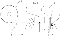
- FIG. 6 shows a label printer 1 'in the process of retraction in which the feed unit 8' has two opposing roles.
- the method shown here can be used not only in label printers for scales, but also in other control devices in which the result of the control is confirmed with a label. Also possible is the use of the method in an automated packaging system, where the label is fully automatically attached to the controlled goods.
Landscapes
- Handling Of Sheets (AREA)
- Printers Characterized By Their Purpose (AREA)
- Labeling Devices (AREA)
Description
Die Erfindung betrifft ein Verfahren zum Bedrucken und Abtrennen von trägerlosen Etiketten für einen Etikettendrucker.The invention relates to a method for printing and separating carrierless labels for a label printer.
Etikettendrucker werden häufig zusammen mit einem Inspektionsgerät, z.B. einer Waage verwendet. Weit verbreitet ist diese Kombination in Einkaufsläden wo der Kunde seine Ware (Gemüse, Früchte, Fleisch, etc.) selbst auf die Waage legt und diese wiegt. Die Waage berechnet nach Eingabe einer der Ware entsprechenden Nummer den Kaufpreis der gewogenen Ware und lässt über den angeschlossenen Etikettendrucker das Preisetikett drucken.Label printers are often used in conjunction with an inspection device, e.g. a balance used. This combination is widely used in shops where the customer puts his goods (vegetables, fruits, meat, etc.) on the scales and weighs them. After entering a number corresponding to the product, the balance calculates the purchase price of the weighed goods and prints the price label via the connected label printer.
Unter den Etikettendrucker gibt es verschiedene Typen unterteilt nach Art der Etikette. Zum einen gibt es Etiketten, die auf einer Trägerfolie aufgeklebt sind und nach dem Bedrucken abgelöst und durch einen Öffnungsschlitz ausgegeben werden. Der Kunde entnimmt dem Drucker das Etikett und klebt es auf die von Ihm zu kennzeichnende Ware. Diese Art von Etikett hat immer dieselbe Grösse, wodurch der Platz zum Bedrucken vorgegeben ist. Die Trägerfolie muss nach dem Ablösen des Etiketts, meinst im Etikettendrucker selbst, wieder aufgerollt werden. Ein weiterer Nachteil dieser Art von Etiketten ist das erschwerte Wechseln bzw. Einlegen einer neuen Rolle mit Etiketten sowie die Notwendigkeit einer Erkennung des Etiketts auf der Trägerfolie und einer damit verbundenen Synchronisation der Vorschubeinheit mit der Druckeinheit.Among the label printers, there are various types divided by type of label. On the one hand, there are labels that are glued to a carrier foil and are detached after printing and output through an opening slit. The customer removes the label from the printer and sticks it to the goods to be labeled by him. This type of label is always the same size, which dictates the space for printing. The carrier foil must be rolled up again after the label has been detached, say in the label printer itself. Another disadvantage of this type of labels is the difficulty of changing or inserting a new roll of labels as well as the need to recognize the label on the carrier film and an associated synchronization of the feed unit with the printing unit.
Um den Nachteil einer Trägerfolie zu überwinden wurden Trägerlosetiketten entwickelt. Dabei handelt es sich um ein Etikettenpapier, das auf einer Seite mit einem Kleber versehen ist. Diese Art von Etiketten benötigt im Gegensatz zu Etiketten auf Trägerfolien eine Schneideinrichtung, die das bedruckte Trägerlosetikett vom unbedruckten Trägerlosetikettenband abtrennt. Beim Kontakt der Klingen der Schneideinrichtung mit dem Etikettenpapier können Kleberrückstände an den Klingen haften bleiben, welche im Verlaufe der Zeit die Schneidleistung vermindern, so dass es zu unsauberen Schnitten kommen kann oder die Schneideinrichtung sogar verklemmt.To overcome the disadvantage of a carrier film, strapless labels have been developed. This is a label paper, which is provided on one side with an adhesive. This type of label, unlike labels on carrier sheets, requires a cutter which separates the printed carrier label from the unprinted carrier label tape. Upon contact of the blades of the cutter with the label paper, adhesive residues may adhere to the blades which, over time, reduce the cutting performance so that unclean cuts may occur or the cutter may even jam.
Nach heutigem Stand der Technik sind zwei Lösungen bekannt um dem Verkleben der Klingen entgegenzuwirken. Zum einen wird der Kleber nicht durchgehend auf das Etikettenpapier aufgetragen, sondern mit Unterbrechungen, die dazu genutzt werden das Etikett an dieser Stelle abzutrennen. Dies hat den Nachteil dass auch hier die Grösse des Etiketts vorgegeben ist, d.h. das Etikett wird immer an der nächstfolgenden Unterbrechung des Klebers abgetrennt. Je nach Intervall von Kleber und Unterbrechung wird einmal mehr und ein anderes Mal weniger Etikettenpapier verwendet, jedoch in der Regel immer mehr als nötig. Zudem ist dabei eine Synchronisation zwischen Vorschubeinheit und Schneideinheit sicherstellen, dass nur an den Stellen einer Unterbrechung eine Abtrennung erfolgt. Dies wird meist durch eine Markierung auf dem Trägerlosetikettenband erreicht. Das Anbringen der Markierung und das Aufbringen des Klebers mit Unterbrechungen verteuern allerdings das Etikettenpapier in dessen Herstellung enorm.According to the current state of the art, two solutions are known to counteract the sticking of the blades. On the one hand, the adhesive is not applied continuously to the label paper, but intermittently, which are used to separate the label at this point. This has the disadvantage that here, too Size of the label is specified, ie the label is always separated at the next interruption of the adhesive. Depending on the interval of glue and interruption, more and less label paper is used, but usually more than necessary. In addition, a synchronization between the feed unit and the cutting unit ensures that separation takes place only at the points of interruption. This is usually achieved by marking on the strapless label tape. However, the application of the mark and the application of the adhesive with interruptions increase the cost of label paper in its production enormously.
Ebenfalls bekannt ist Etikettenpapier mit nicht vollflächig aufgetragenem Kleber, das heisst, dass der Kleber ein Muster von Kleber und kleberfreien Stellen aufweist. Diese Muster können ähnlich einer Schraffur sein, zum Beispiel feine um ca. 45° zum Trägerlosetikettenband verlaufende Bahnen, gekreuzte Bahnen oder Bahnen in V-Form.Also known is label paper with not fully applied adhesive, which means that the adhesive has a pattern of adhesive and glue-free areas. These patterns may be similar to hatching, for example fine webs running at about 45 ° to the carrierless label web, crossed webs or webs in V form.
In einer anderen Lösung gemäss
Das Dokument
Aufgabe der Erfindung ist es ein Verfahren zu schaffen, dass die Nachteile des Standes der Technik überwindet, d.h. dass das Etikett an jeder beliebigen Stelle abgetrennt werden kann ohne dass dabei die Schnittleitung der Klinge bzw. des Etikettendruckers vermindert wird und dabei auf eine Benetzung der Klingen mit Öl verzichtet werden kann.The object of the invention is to provide a method that overcomes the disadvantages of the prior art, i. that the label can be separated at any point without the cutting line of the blade or the label printer is reduced and can be dispensed wetting the blades with oil.
Diese Aufgabe wird gelöst durch das Verfahren gemäss Anspruch 1. Das Verfahren zum Bedrucken und Abtrennen von Trägerlosetiketten für einen Etikettendrucker, der eine Druckeinheit, eine Aufnahme des Trägerlosetikettenbandes, eine Schneideinrichtung mit mindestens zwei auf jeweils beiden Seiten des Trägerlosetikettenbandes angeordneten Klingen, und eine Vorschubeinheit aufweist, führt mindestens die nachfolgenden Schritte aus. Ein Vorschieben des Trägerlosetikettenbands mittels der Vorschubeinheit durch die Druckeinheit und durch die Schneideinrichtung. Dabei erfolgt zwischenzeitlich ein teilweises Bedrucken des Trägerlosetikettenbandes während des Vorschiebens mittels der Druckeinheit. Ist das Bedrucken abgeschlossen erfolgt ein Abtrennen des bedruckten Trägerlosetiketts vom Trägerlosetikettenband mittels Zusammenfahren der Klingen. Ein Auseinanderfahren der Klingen bringt diese in eine Ausgangsposition zum erneuten Abtrennen.This object is achieved by the method of
Erfindungsgemäss erfolgt vor dem Schritt des Auseinanderfahrens der Klingen ein Zurückziehen des Trägerlosetikettenbandes von den Klingen. Es entsteht so ein Abstand zwischen dem Trägerlosetikettenband und den Klingen.According to the invention, before the step of moving the blades apart, the straps of the straps are retracted from the blades. This creates a gap between the strapless label tape and the blades.
Eine Analyse des Problems des Anhaftens von Kleber an den Klingen hat gezeigt, dass beim Auseinanderfahren der Klingen das unbedruckte Trägerlosetikettenband an der Klinge streift und so der Kleber auf die Klingen gelangt. Das Zurückziehen des Bandes, bevor die Klingen zurück in die Position zum erneuten Abtrennen geführt werden, verhindert wirkungsvoll das Anhaften von Kleber an den Klingen. Das Erfinderische Verfahren erreicht dadurch eine unverminderte Schnittleistung.An analysis of the problem of glue sticking to the blades has shown that as the blades move apart, the unprinted, strapless label tape rubs against the blade, causing the glue to get on the blades. Retracting the tape before the blades are returned to the re-severing position effectively prevents adhesive from adhering to the blades. The inventive method thereby achieves undiminished cutting performance.
Weiter erreicht das Verfahren einen sparsamen Verbrauch von Etikettenpapier, da sowohl der Schnitt nicht weiter entfernt als nötig angesetzt werden kann, als auch der Start des neuen Etikettendrucks näher am abgetrennten Ende des unbedruckten Trägerlosetikettenbands beginnen kann.Further, the method achieves economical consumption of label paper, as both the cut can not be made farther than necessary, and the start of new label printing can begin nearer the severed end of the unprinted liner label tape.
In einer Weiterbildung des erfinderischen Verfahrens erfolgt das Auseinanderfahren der beiden Klingen, sobald kein Kontakt mehr zwischen dem Trägerlosetikettenband und den Klingen besteht. Dadurch verkürzt sich die Zeit zum Ausführen des Verfahrens durch gleichzeitiges Ausführen zweier Verfahrensschritte.In a further development of the inventive method, the moving apart of the two blades takes place as soon as there is no contact between the strapless label tape and the blades. This shortens the time for executing the method by simultaneously performing two method steps.
In einer weiteren Weiterbildung des erfinderischen Verfahrens weist die Druckeinheit einen Druckkopf auf, wobei der maximale Abstand zwischen Trägerlosetikettenband und den Klingen nach dem Zurückziehen der Distanz zwischen dem Druckkopf und den Klingen entspricht.In a further development of the inventive method, the printing unit has a print head, wherein the maximum distance between the strapless label tape and the blades after retraction corresponds to the distance between the print head and the blades.
Das erfinderische Verfahren kann zudem dadurch gekennzeichnet sein, dass die zwei Klingen der Schneideinrichtung beim Abtrennvorgang das Trägerlosetikettenband in dessen ganzen Breite durchtrennen.The inventive method can also be characterized in that the two blades of the cutting device in the separation process cut through the strapless Lotetikettenband in its entire width.
In einer zusätzlichen Weiterbildung des Verfahrens kommen die zwei Klingen der Schneideinrichtung beim Abtrennvorgang nur punktuell in Kontakt mit dem Trägerlosetikettenband und schneiden dabei das Trägerlosetikettenband (7) zwischen einem spitzen Winkel. Zum Beispiel führen die Klingen beim Abtrennvorgang eine Linearbewegung aus. Dadurch wird zusätzlich die Lebensdauer der Klingen erhöht und das Anhaften von Kleber vermindert. Diese Art des Abtrennens benötigt auch weniger Kraft um das Trägerlosetikettenband zu durchtrennen.In an additional development of the method, the two blades of the cutting device in the separation process come only selectively in contact with the Trägerlosetikettenband and thereby cut the Trägerlosetikettenband (7) between an acute angle. For example, the blades perform a linear motion during the separation process. This also increases the life of the blades and reduces the adhesion of adhesive. This type of severing also requires less force to sever the strapping label tape.
In einer weiteren Weiterentwicklung des Verfahrens weist der Etikettendrucker ferner ein Auflageelement mit einem Sensor auf, auf das ein abgetrenntes Trägerlosetikett nach dem Abtrennen fällt. Durch das Signal des Sensors erfolgt die Freigabe für die nachfolgende Ausgabe eines Trägerlosetiketts erst, wenn auf dem Ablageelement kein Trägerlosetikett liegt. Auf diese Weise wird verhindert, dass zwei Trägerlosetiketts aneinander festkleben.In a further development of the method, the label printer further comprises a support element with a sensor on which a separated carrier label falls after separation. By the signal of the sensor, the release for the subsequent issue of a carrier label takes place only when there is no Trägerlosetikett on the storage element. This will prevent two strapless labels from sticking to each other.
In einer Ausgestaltung ist eine der zwei Klingen fest mit dem Etikettendrucker verbunden und die andere Klinge gegenüber dem Etikettendrucker beweglich angeordnet. Weiter kann die feststehende Klinge nahe dem Auflageelement angeordnet sein, so dass nach dem Zusammenfahren der Klingen sich die feststehende Klinge zwischen der beweglichen Klinge und dem Auflageelement befindet.In one embodiment, one of the two blades is fixedly connected to the label printer and the other blade is arranged to be movable relative to the label printer. Further, the fixed blade may be disposed near the support member so that after the blades collapse, the fixed blade is between the movable blade and the support member.
In einer weiteren Ausgestaltung ist die bewegliche Klinge in Ausgaberichtung des Trägerlosetiketts vor der feststehenden Klinge angeordnet.In a further embodiment, the movable blade is arranged in the discharge direction of the carrier lot label in front of the fixed blade.
In einem computergestütztem Programm zur Ausführung des Verfahrens zum Bedrucken und Abtrennen von Trägerlosetiketten wird ein Signal zur Auslösung eines Zurückziehens des Trägerlosetikettenbandes zur Ausgabe gebracht. Der Etikettendrucker weist dabei eine Druckeinheit, eine Schneideinrichtung mit mindestens zwei Klingen, eine Aufnahme des Trägerlosetikettenbandes, und eine Vorschubeinheit auf.In a computer-aided program for carrying out the method of printing and separating carrierless labels, a signal for initiating retraction of the carrierless label tape is output. The label printer in this case has a printing unit, a cutting device with at least two blades, a receptacle of the carrier label tape, and a feed unit.
Das erfinderische Verfahren und dessen Einsatz in einem Etikettendrucker werden anhand der folgenden Figuren näher beschrieben, wobei gleiche Elemente mit denselben Bezugszeichen versehen sind. Es zeigen:
- Fig. 1
- einen Etikettendrucker beim Bedrucken und Vorschieben des Trägerlosetikettenbandes;
- Fig. 2
- den Etikettendrucker beim Abtrennen des Trägerlosetiketts vom Trägerlosetikettenband;
- Fig. 3
- den Etikettendrucker beim Zurückziehen des Trägerlosetikettenbandes von den Klingen der Schneideinheit;
- Fig. 4
- den Etikettendrucker beim Auseinanderfahren der Klingen der Schneideinheit; und
- Fig. 5
- ein Ablaufdiagramm mit den Schritten des Verfahrens zum Bedrucken und Abtrennen von Trägerlosetiketten für einen Etikettendrucker.
- Fig. 1
- a label printer when printing and advancing the strapless label tape;
- Fig. 2
- the label printer when separating the carrier label from the carrier label tape;
- Fig. 3
- the label printer when retracting the strapless label tape from the blades of the cutting unit;
- Fig. 4
- the label printer when moving apart the blades of the cutting unit; and
- Fig. 5
- a flow chart with the steps of the method for printing and separating carrier label for a label printer.
Die
Vorwärts bedeutet hier die Richtung der Ausgabe von Etiketten. In den
In den
Die
In
Im kennzeichnenden Schritt des Verfahrens wird nun, wie in
Beim Zurückziehen sollte darauf geachtet werden, dass das Trägerlosetikettenband 7 nicht aus dessen Führung ausfährt. Den weitesten Abstand z wird erreicht wenn das Trägerlosetikettenband 7 bis zum Druckkopf der Druckeinheit 2 zurückgezogen wird. In Zahlen ausgedrückt beträgt der Abstand z 0,5 bis 5 cm.When retracting care should be taken that the
In
Wird das bedruckte Trägerlosetikett 9 nicht durch den Benutzer entfernt fällt es auf ein Ablageelement 10. Ein Sensor 11 erkennt ob sich ein Trägerlosetikett 9 auf dem Ablageelement 10 befindet. Das Signal des Sensors 11 kann verwendet werden um zu verhindern, dass eine nachfolgende Ausgabe eines Trägerlosetiketts startet bevor das eben gedruckte Trägerlosetikett 9 entfernt wurde. Auf diese Weise wird verhindert, dass zwei Trägerlosetiketts aneinander festkleben.If the printed
Als Sensor 11 können verschiedenste Typen zur Anwendung kommen, zum Beispiel vom Typ Reflexionslichtschranke.As
Natürlich kann das hier gezeigte Verfahren nicht nur in Etikettendrucker für Waagen zum Einsatz kommen, sondern auch bei anderen Kontrollgeräten bei denen das Resultat der Kontrolle mit einem Etikett bestätigt wird. Ebenfalls möglich ist der Einsatz des Verfahrens in einer automatisierten Verpackungsanlage, wo das Etikett vollautomatisiert an die kontrollierte Ware angebracht wird.Of course, the method shown here can be used not only in label printers for scales, but also in other control devices in which the result of the control is confirmed with a label. Also possible is the use of the method in an automated packaging system, where the label is fully automatically attached to the controlled goods.
- 1,1'1,1 '
- Etikettendruckerlabel printers
- 2,2'2,2 '
- Druckeinheitprinting unit
- 33
- Schneideinrichtungcutter
- 4,54.5
- KlingenSound
- 66
- Aufnahmeadmission
- 77
- TrägerlosetikettenbandesTrägerlosetikettenbandes
- 8,8'8,8 '
- Vorschubeinheitfeed unit
- 99
- TrägerlosetikettTrägerlosetikett
- 1010
- Ablageelementstorage element
- 1111
- Sensorsensor
Claims (11)
- Method for a label printer (1, 1') to print and separate linerless labels, wherein the label printer (1, 1') comprises
a printing unit (2, 2'), a holder (6) for a linerless label ribbon (7), a cutting unit (3) with at least two blades (4, 5) arranged, respectively, on the two sides of the linerless label ribbon (7), and a paper-feeding unit (8, 8'),
wherein the method comprises the following steps:- by means of the paper-feeding unit (8, 8'), advancing the linerless label ribbon (7) through the printing unit (2, 2') and through the cutting unit (3);- during the feed advancement, printing on a part of the linerless label ribbon (7) by means of the printing unit (2, 2');- separating the printed linerless label (9) from the linerless label ribbon (7) by means of the blades (4, 5) closing against each other;- moving the blades (4, 5) apart from each other into a starting position for a next cutting operation;characterized in that
prior to moving the blades (4, 5) apart from each other, the linerless label ribbon (7) is pulled back from the blades (4, 5), so that a distance (z) is created between the linerless label ribbon (7) and the blades (4, 5). - Method according to claim 1, characterized in that the moving the blades (4, 5) apart from each other occurs as soon as the linerless label ribbon (7) is out of contact with the blades (4, 5).
- Method according to one of the claims 1 or 2, characterized in that the printing unit (2, 2') has a print head and that the maximum distance (z) of the linerless label ribbon (7) from the blades (4, 5) after the pulling back equals the distance between the print head and the blades (4, 5).
- Method according to one of the claims 1 to 3, characterized in that in the cutting operation the two blades (4, 5) of the cutting unit (3) sever the linerless label ribbon (7) across its entire width.
- Method according to one of the claims 1 to 4, characterized in that the two blades (4, 5) of the cutting unit (3) are contacting the linerless label ribbon (7) between them only in a point during the cutting process and are shearing the linerless label between them under an acute angle.
- Method according to claim 5, characterized in that the blades (4, 5) perform a translatory movement during the cutting process.
- Method according to one of the claims 1 to 6, characterized in that the label printer (1') further includes a receiving element (10) with a sensor (11) onto which a linerless label (9) falls after it has been cut, wherein in response to the signal of the sensor (11), a next-following linerless label is released for delivery if no linerless label (9) is present on the receiving element (10).
- Method according to one of the claims 1 to 7, characterized in that of the two blades, one blade (5) is solidly connected to the label printer (1, 1'), while the other blade (4) is arranged to be movable relative to the label printer (1, 1').
- Method according to claim 8, characterized in that the stationary blade (5) is arranged close to the receiving element (10), so that after the closing of the blades (4, 5) against each other the stationary blade (5) lies between the movable blade (4) and the receiving element (10).
- Method according to one of the claims 8 or 9, characterized in that, relative to the output direction of the linerless label, the movable blade (4) is arranged on the forward-facing side of the stationary blade (5).
- Computer-assisted program for the implementation of the method for a label printer (1, 1') to print and separate linerless labels according to one of the claims 1 to 10, wherein a signal is generated which serves to trigger a pulling-back movement of the linerless label ribbon (7).
Priority Applications (3)
| Application Number | Priority Date | Filing Date | Title |
|---|---|---|---|
| EP16197658.4A EP3318412B1 (en) | 2016-11-08 | 2016-11-08 | Label printer for carrier-free labels |
| US15/784,732 US10265968B2 (en) | 2016-11-08 | 2017-10-16 | Label printer for linerless labels |
| CN201711082964.5A CN108068469B (en) | 2016-11-08 | 2017-11-07 | Label printer for linerless labels |
Applications Claiming Priority (1)
| Application Number | Priority Date | Filing Date | Title |
|---|---|---|---|
| EP16197658.4A EP3318412B1 (en) | 2016-11-08 | 2016-11-08 | Label printer for carrier-free labels |
Publications (2)
| Publication Number | Publication Date |
|---|---|
| EP3318412A1 EP3318412A1 (en) | 2018-05-09 |
| EP3318412B1 true EP3318412B1 (en) | 2019-10-16 |
Family
ID=57249737
Family Applications (1)
| Application Number | Title | Priority Date | Filing Date |
|---|---|---|---|
| EP16197658.4A Active EP3318412B1 (en) | 2016-11-08 | 2016-11-08 | Label printer for carrier-free labels |
Country Status (3)
| Country | Link |
|---|---|
| US (1) | US10265968B2 (en) |
| EP (1) | EP3318412B1 (en) |
| CN (1) | CN108068469B (en) |
Cited By (1)
| Publication number | Priority date | Publication date | Assignee | Title |
|---|---|---|---|---|
| US11685134B2 (en) | 2020-07-10 | 2023-06-27 | Bizerba SE & Co. KG | Method of cutting off labels |
Families Citing this family (5)
| Publication number | Priority date | Publication date | Assignee | Title |
|---|---|---|---|---|
| CN110484148A (en) * | 2019-07-12 | 2019-11-22 | 嘉兴市豪能科技股份有限公司 | A kind of pressure-sensitive lacquer disk(-sc) mark of local positioning and its production technology |
| JP7215520B2 (en) * | 2020-07-17 | 2023-01-31 | カシオ計算機株式会社 | PRINTING DEVICE, CONTROL METHOD, AND PROGRAM |
| CN113942316B (en) * | 2020-07-17 | 2023-06-20 | 卡西欧计算机株式会社 | Printing apparatus, control method, and storage medium |
| CN112478357B (en) * | 2020-10-26 | 2022-08-19 | 浙江弘益塑业有限公司 | Hose gummed paper pasting tool |
| CN114851726A (en) * | 2022-05-26 | 2022-08-05 | 广州鑫源网络科技有限公司 | Paper detection method of portable label printer |
Family Cites Families (16)
| Publication number | Priority date | Publication date | Assignee | Title |
|---|---|---|---|---|
| US5223940A (en) * | 1987-11-13 | 1993-06-29 | Canon Kabushiki Kaisha | Image recording apparatus with control of cutter blades and retraction of recording medium web in response to detection of a cut sheet |
| US6210515B1 (en) * | 1995-02-27 | 2001-04-03 | Moore Business Forms, Inc. | Linerless label printer control |
| US6129810A (en) * | 1995-10-17 | 2000-10-10 | Moore Business Forms, Inc. | Linerless label dispenser |
| US5853117A (en) * | 1995-10-31 | 1998-12-29 | Moore Business Forms, Inc. | Separator for linerless labels |
| JPH10268776A (en) * | 1997-03-26 | 1998-10-09 | Nitto Denko Corp | Manufacture of linerless label |
| JP4006982B2 (en) * | 2001-11-16 | 2007-11-14 | セイコーエプソン株式会社 | Printer and printer unit |
| JP2004148442A (en) * | 2002-10-30 | 2004-05-27 | Sato Corp | Cutter unit of label printer |
| US20050139323A1 (en) | 2003-04-11 | 2005-06-30 | Syde Gary V. | Linerless label application assembly |
| JP4627085B2 (en) * | 2005-07-27 | 2011-02-09 | 三菱電機株式会社 | Printing apparatus and printing method |
| JP5074562B2 (en) * | 2010-07-29 | 2012-11-14 | 東芝テック株式会社 | Cutter unit and printer |
| JP5830389B2 (en) * | 2012-01-19 | 2015-12-09 | 富士通コンポーネント株式会社 | Printer device and printer device control method |
| JP2014162543A (en) * | 2013-02-27 | 2014-09-08 | Seiko Instruments Inc | Adhesive label issuing device and printer |
| JP6317157B2 (en) * | 2014-03-31 | 2018-04-25 | サトーホールディングス株式会社 | Mountless prevention device for label without mount in thermal printer and label leading edge setting method |
| JP6409426B2 (en) | 2014-04-30 | 2018-10-24 | 株式会社寺岡精工 | Blade body, cutter unit, label issuing device, and oil application method to blade body |
| JP6425449B2 (en) * | 2014-08-05 | 2018-11-21 | サトーホールディングス株式会社 | Thermal printing apparatus and control method thereof |
| US10052884B2 (en) * | 2014-10-28 | 2018-08-21 | Ishida Co., Ltd. | Label issuing apparatus |
-
2016
- 2016-11-08 EP EP16197658.4A patent/EP3318412B1/en active Active
-
2017
- 2017-10-16 US US15/784,732 patent/US10265968B2/en active Active
- 2017-11-07 CN CN201711082964.5A patent/CN108068469B/en active Active
Non-Patent Citations (1)
| Title |
|---|
| None * |
Cited By (1)
| Publication number | Priority date | Publication date | Assignee | Title |
|---|---|---|---|---|
| US11685134B2 (en) | 2020-07-10 | 2023-06-27 | Bizerba SE & Co. KG | Method of cutting off labels |
Also Published As
| Publication number | Publication date |
|---|---|
| US10265968B2 (en) | 2019-04-23 |
| US20180126757A1 (en) | 2018-05-10 |
| CN108068469A (en) | 2018-05-25 |
| EP3318412A1 (en) | 2018-05-09 |
| CN108068469B (en) | 2021-01-26 |
Similar Documents
| Publication | Publication Date | Title |
|---|---|---|
| EP3318412B1 (en) | Label printer for carrier-free labels | |
| DE102005033486A1 (en) | Device and method for splicing label strips | |
| DE2406230A1 (en) | ROTARY PRINTING MACHINE FOR LABELS, IN PARTICULAR SELF-ADHESIVE LABELS | |
| EP0360108B1 (en) | Process and apparatus for delivering labels | |
| DE2134074C3 (en) | Hand-held labeling machine | |
| DE1205888B (en) | Device for printing and outputting adhesive labels and associated label tapes | |
| EP1740389B1 (en) | Method and control unit for a label printer | |
| EP2763921B1 (en) | Apparatus and method for providing film sheets, application apparatus for populating articles with film sheets | |
| EP2851168B1 (en) | Device for punching out labels with counter punch tape | |
| EP0509419B1 (en) | Method and apparatus for separating an element from a laminated sheet | |
| DE10242477B4 (en) | Device for printing on one or more objects movable in a feed direction | |
| DE1436633C3 (en) | Device for producing printed labels | |
| EP1053289B1 (en) | Self-adhesive label roll | |
| DE1929592A1 (en) | Machine for transferring legible information to moving objects | |
| DE1933850B2 (en) | Hand-held labeling device for applying self-adhesive labels, which are detachably arranged on a carrier tape, to objects | |
| DE4026144A1 (en) | METHOD FOR PRODUCING A CONTINUM OF STICKERS | |
| EP1813536B1 (en) | Device for applying adhesive labels | |
| DE2331653B2 (en) | TRANSPORT AND SEPARATION DEVICE FOR RAIL-SHAPED COPY MATERIAL IN PARTICULAR A LIGHTING MACHINE | |
| WO2011042199A1 (en) | Bundling device | |
| AT404916B (en) | DEVICE FOR MARKING BEAMS, BOARDS, EDGEWOODS AND THE LIKE | |
| DE1786569B2 (en) | ||
| DE102019125352B4 (en) | Web shifting device for label printing machines and label processing machines | |
| DE10351877A1 (en) | Cutting device for cutting off labels from a linerless adhesive band, especially for use with a print device, has a counter knife that is moved away from the adhesive label band during transport and moved against it during cutting | |
| DE2615136A1 (en) | Fixture for small parts to web - has web coated with adhesive layer to receive plates applied by stamp | |
| DE2430105A1 (en) | METHOD FOR FEEDING TAPE MATERIAL AT A VERY RAPIDLY CHANGING SPEED AND DEVICE FOR PUSHING THESE TAPES |
Legal Events
| Date | Code | Title | Description |
|---|---|---|---|
| PUAI | Public reference made under article 153(3) epc to a published international application that has entered the european phase |
Free format text: ORIGINAL CODE: 0009012 |
|
| STAA | Information on the status of an ep patent application or granted ep patent |
Free format text: STATUS: THE APPLICATION HAS BEEN PUBLISHED |
|
| AK | Designated contracting states |
Kind code of ref document: A1 Designated state(s): AL AT BE BG CH CY CZ DE DK EE ES FI FR GB GR HR HU IE IS IT LI LT LU LV MC MK MT NL NO PL PT RO RS SE SI SK SM TR |
|
| AX | Request for extension of the european patent |
Extension state: BA ME |
|
| STAA | Information on the status of an ep patent application or granted ep patent |
Free format text: STATUS: REQUEST FOR EXAMINATION WAS MADE |
|
| 17P | Request for examination filed |
Effective date: 20181026 |
|
| RBV | Designated contracting states (corrected) |
Designated state(s): AL AT BE BG CH CY CZ DE DK EE ES FI FR GB GR HR HU IE IS IT LI LT LU LV MC MK MT NL NO PL PT RO RS SE SI SK SM TR |
|
| GRAP | Despatch of communication of intention to grant a patent |
Free format text: ORIGINAL CODE: EPIDOSNIGR1 |
|
| STAA | Information on the status of an ep patent application or granted ep patent |
Free format text: STATUS: GRANT OF PATENT IS INTENDED |
|
| INTG | Intention to grant announced |
Effective date: 20190510 |
|
| GRAS | Grant fee paid |
Free format text: ORIGINAL CODE: EPIDOSNIGR3 |
|
| GRAA | (expected) grant |
Free format text: ORIGINAL CODE: 0009210 |
|
| STAA | Information on the status of an ep patent application or granted ep patent |
Free format text: STATUS: THE PATENT HAS BEEN GRANTED |
|
| AK | Designated contracting states |
Kind code of ref document: B1 Designated state(s): AL AT BE BG CH CY CZ DE DK EE ES FI FR GB GR HR HU IE IS IT LI LT LU LV MC MK MT NL NO PL PT RO RS SE SI SK SM TR |
|
| REG | Reference to a national code |
Ref country code: GB Ref legal event code: FG4D Free format text: NOT ENGLISH |
|
| REG | Reference to a national code |
Ref country code: CH Ref legal event code: EP |
|
| REG | Reference to a national code |
Ref country code: DE Ref legal event code: R096 Ref document number: 502016007099 Country of ref document: DE |
|
| REG | Reference to a national code |
Ref country code: IE Ref legal event code: FG4D Free format text: LANGUAGE OF EP DOCUMENT: GERMAN |
|
| REG | Reference to a national code |
Ref country code: AT Ref legal event code: REF Ref document number: 1190905 Country of ref document: AT Kind code of ref document: T Effective date: 20191115 |
|
| REG | Reference to a national code |
Ref country code: NL Ref legal event code: MP Effective date: 20191016 |
|
| REG | Reference to a national code |
Ref country code: LT Ref legal event code: MG4D |
|
| PG25 | Lapsed in a contracting state [announced via postgrant information from national office to epo] |
Ref country code: LT Free format text: LAPSE BECAUSE OF FAILURE TO SUBMIT A TRANSLATION OF THE DESCRIPTION OR TO PAY THE FEE WITHIN THE PRESCRIBED TIME-LIMIT Effective date: 20191016 Ref country code: NL Free format text: LAPSE BECAUSE OF FAILURE TO SUBMIT A TRANSLATION OF THE DESCRIPTION OR TO PAY THE FEE WITHIN THE PRESCRIBED TIME-LIMIT Effective date: 20191016 Ref country code: FI Free format text: LAPSE BECAUSE OF FAILURE TO SUBMIT A TRANSLATION OF THE DESCRIPTION OR TO PAY THE FEE WITHIN THE PRESCRIBED TIME-LIMIT Effective date: 20191016 Ref country code: BG Free format text: LAPSE BECAUSE OF FAILURE TO SUBMIT A TRANSLATION OF THE DESCRIPTION OR TO PAY THE FEE WITHIN THE PRESCRIBED TIME-LIMIT Effective date: 20200116 Ref country code: PT Free format text: LAPSE BECAUSE OF FAILURE TO SUBMIT A TRANSLATION OF THE DESCRIPTION OR TO PAY THE FEE WITHIN THE PRESCRIBED TIME-LIMIT Effective date: 20200217 Ref country code: NO Free format text: LAPSE BECAUSE OF FAILURE TO SUBMIT A TRANSLATION OF THE DESCRIPTION OR TO PAY THE FEE WITHIN THE PRESCRIBED TIME-LIMIT Effective date: 20200116 Ref country code: GR Free format text: LAPSE BECAUSE OF FAILURE TO SUBMIT A TRANSLATION OF THE DESCRIPTION OR TO PAY THE FEE WITHIN THE PRESCRIBED TIME-LIMIT Effective date: 20200117 Ref country code: PL Free format text: LAPSE BECAUSE OF FAILURE TO SUBMIT A TRANSLATION OF THE DESCRIPTION OR TO PAY THE FEE WITHIN THE PRESCRIBED TIME-LIMIT Effective date: 20191016 Ref country code: LV Free format text: LAPSE BECAUSE OF FAILURE TO SUBMIT A TRANSLATION OF THE DESCRIPTION OR TO PAY THE FEE WITHIN THE PRESCRIBED TIME-LIMIT Effective date: 20191016 Ref country code: SE Free format text: LAPSE BECAUSE OF FAILURE TO SUBMIT A TRANSLATION OF THE DESCRIPTION OR TO PAY THE FEE WITHIN THE PRESCRIBED TIME-LIMIT Effective date: 20191016 |
|
| PG25 | Lapsed in a contracting state [announced via postgrant information from national office to epo] |
Ref country code: HR Free format text: LAPSE BECAUSE OF FAILURE TO SUBMIT A TRANSLATION OF THE DESCRIPTION OR TO PAY THE FEE WITHIN THE PRESCRIBED TIME-LIMIT Effective date: 20191016 Ref country code: RS Free format text: LAPSE BECAUSE OF FAILURE TO SUBMIT A TRANSLATION OF THE DESCRIPTION OR TO PAY THE FEE WITHIN THE PRESCRIBED TIME-LIMIT Effective date: 20191016 Ref country code: IS Free format text: LAPSE BECAUSE OF FAILURE TO SUBMIT A TRANSLATION OF THE DESCRIPTION OR TO PAY THE FEE WITHIN THE PRESCRIBED TIME-LIMIT Effective date: 20200224 |
|
| PG25 | Lapsed in a contracting state [announced via postgrant information from national office to epo] |
Ref country code: AL Free format text: LAPSE BECAUSE OF FAILURE TO SUBMIT A TRANSLATION OF THE DESCRIPTION OR TO PAY THE FEE WITHIN THE PRESCRIBED TIME-LIMIT Effective date: 20191016 |
|
| REG | Reference to a national code |
Ref country code: DE Ref legal event code: R097 Ref document number: 502016007099 Country of ref document: DE |
|
| PG2D | Information on lapse in contracting state deleted |
Ref country code: IS |
|
| PG25 | Lapsed in a contracting state [announced via postgrant information from national office to epo] |
Ref country code: LU Free format text: LAPSE BECAUSE OF NON-PAYMENT OF DUE FEES Effective date: 20191108 Ref country code: RO Free format text: LAPSE BECAUSE OF FAILURE TO SUBMIT A TRANSLATION OF THE DESCRIPTION OR TO PAY THE FEE WITHIN THE PRESCRIBED TIME-LIMIT Effective date: 20191016 Ref country code: MC Free format text: LAPSE BECAUSE OF FAILURE TO SUBMIT A TRANSLATION OF THE DESCRIPTION OR TO PAY THE FEE WITHIN THE PRESCRIBED TIME-LIMIT Effective date: 20191016 Ref country code: DK Free format text: LAPSE BECAUSE OF FAILURE TO SUBMIT A TRANSLATION OF THE DESCRIPTION OR TO PAY THE FEE WITHIN THE PRESCRIBED TIME-LIMIT Effective date: 20191016 Ref country code: ES Free format text: LAPSE BECAUSE OF FAILURE TO SUBMIT A TRANSLATION OF THE DESCRIPTION OR TO PAY THE FEE WITHIN THE PRESCRIBED TIME-LIMIT Effective date: 20191016 Ref country code: EE Free format text: LAPSE BECAUSE OF FAILURE TO SUBMIT A TRANSLATION OF THE DESCRIPTION OR TO PAY THE FEE WITHIN THE PRESCRIBED TIME-LIMIT Effective date: 20191016 Ref country code: CZ Free format text: LAPSE BECAUSE OF FAILURE TO SUBMIT A TRANSLATION OF THE DESCRIPTION OR TO PAY THE FEE WITHIN THE PRESCRIBED TIME-LIMIT Effective date: 20191016 Ref country code: IS Free format text: LAPSE BECAUSE OF FAILURE TO SUBMIT A TRANSLATION OF THE DESCRIPTION OR TO PAY THE FEE WITHIN THE PRESCRIBED TIME-LIMIT Effective date: 20200216 |
|
| PLBE | No opposition filed within time limit |
Free format text: ORIGINAL CODE: 0009261 |
|
| REG | Reference to a national code |
Ref country code: BE Ref legal event code: MM Effective date: 20191130 |
|
| STAA | Information on the status of an ep patent application or granted ep patent |
Free format text: STATUS: NO OPPOSITION FILED WITHIN TIME LIMIT |
|
| PG25 | Lapsed in a contracting state [announced via postgrant information from national office to epo] |
Ref country code: SM Free format text: LAPSE BECAUSE OF FAILURE TO SUBMIT A TRANSLATION OF THE DESCRIPTION OR TO PAY THE FEE WITHIN THE PRESCRIBED TIME-LIMIT Effective date: 20191016 Ref country code: SK Free format text: LAPSE BECAUSE OF FAILURE TO SUBMIT A TRANSLATION OF THE DESCRIPTION OR TO PAY THE FEE WITHIN THE PRESCRIBED TIME-LIMIT Effective date: 20191016 Ref country code: IT Free format text: LAPSE BECAUSE OF FAILURE TO SUBMIT A TRANSLATION OF THE DESCRIPTION OR TO PAY THE FEE WITHIN THE PRESCRIBED TIME-LIMIT Effective date: 20191016 |
|
| 26N | No opposition filed |
Effective date: 20200717 |
|
| PG25 | Lapsed in a contracting state [announced via postgrant information from national office to epo] |
Ref country code: IE Free format text: LAPSE BECAUSE OF NON-PAYMENT OF DUE FEES Effective date: 20191108 |
|
| PG25 | Lapsed in a contracting state [announced via postgrant information from national office to epo] |
Ref country code: SI Free format text: LAPSE BECAUSE OF FAILURE TO SUBMIT A TRANSLATION OF THE DESCRIPTION OR TO PAY THE FEE WITHIN THE PRESCRIBED TIME-LIMIT Effective date: 20191016 Ref country code: BE Free format text: LAPSE BECAUSE OF NON-PAYMENT OF DUE FEES Effective date: 20191130 |
|
| PG25 | Lapsed in a contracting state [announced via postgrant information from national office to epo] |
Ref country code: CY Free format text: LAPSE BECAUSE OF FAILURE TO SUBMIT A TRANSLATION OF THE DESCRIPTION OR TO PAY THE FEE WITHIN THE PRESCRIBED TIME-LIMIT Effective date: 20191016 |
|
| GBPC | Gb: european patent ceased through non-payment of renewal fee |
Effective date: 20201108 |
|
| PG25 | Lapsed in a contracting state [announced via postgrant information from national office to epo] |
Ref country code: HU Free format text: LAPSE BECAUSE OF FAILURE TO SUBMIT A TRANSLATION OF THE DESCRIPTION OR TO PAY THE FEE WITHIN THE PRESCRIBED TIME-LIMIT; INVALID AB INITIO Effective date: 20161108 Ref country code: MT Free format text: LAPSE BECAUSE OF FAILURE TO SUBMIT A TRANSLATION OF THE DESCRIPTION OR TO PAY THE FEE WITHIN THE PRESCRIBED TIME-LIMIT Effective date: 20191016 |
|
| PG25 | Lapsed in a contracting state [announced via postgrant information from national office to epo] |
Ref country code: GB Free format text: LAPSE BECAUSE OF NON-PAYMENT OF DUE FEES Effective date: 20201108 |
|
| PG25 | Lapsed in a contracting state [announced via postgrant information from national office to epo] |
Ref country code: TR Free format text: LAPSE BECAUSE OF FAILURE TO SUBMIT A TRANSLATION OF THE DESCRIPTION OR TO PAY THE FEE WITHIN THE PRESCRIBED TIME-LIMIT Effective date: 20191016 |
|
| PG25 | Lapsed in a contracting state [announced via postgrant information from national office to epo] |
Ref country code: MK Free format text: LAPSE BECAUSE OF FAILURE TO SUBMIT A TRANSLATION OF THE DESCRIPTION OR TO PAY THE FEE WITHIN THE PRESCRIBED TIME-LIMIT Effective date: 20191016 |
|
| REG | Reference to a national code |
Ref country code: AT Ref legal event code: MM01 Ref document number: 1190905 Country of ref document: AT Kind code of ref document: T Effective date: 20211108 |
|
| PG25 | Lapsed in a contracting state [announced via postgrant information from national office to epo] |
Ref country code: AT Free format text: LAPSE BECAUSE OF NON-PAYMENT OF DUE FEES Effective date: 20211108 |
|
| PGFP | Annual fee paid to national office [announced via postgrant information from national office to epo] |
Ref country code: FR Payment date: 20231123 Year of fee payment: 8 Ref country code: DE Payment date: 20231127 Year of fee payment: 8 Ref country code: CH Payment date: 20231202 Year of fee payment: 8 |