EP3318183A1 - Auxiliary device for blood pressure measurement and blood pressure measuring equipment - Google Patents
Auxiliary device for blood pressure measurement and blood pressure measuring equipment Download PDFInfo
- Publication number
- EP3318183A1 EP3318183A1 EP15896915.4A EP15896915A EP3318183A1 EP 3318183 A1 EP3318183 A1 EP 3318183A1 EP 15896915 A EP15896915 A EP 15896915A EP 3318183 A1 EP3318183 A1 EP 3318183A1
- Authority
- EP
- European Patent Office
- Prior art keywords
- blood pressure
- pulse sound
- pressure
- audio
- terminal device
- Prior art date
- Legal status (The legal status is an assumption and is not a legal conclusion. Google has not performed a legal analysis and makes no representation as to the accuracy of the status listed.)
- Granted
Links
- 230000036772 blood pressure Effects 0.000 title claims abstract description 73
- 238000009530 blood pressure measurement Methods 0.000 title claims abstract description 58
- 230000005236 sound signal Effects 0.000 claims description 98
- 230000005540 biological transmission Effects 0.000 claims description 46
- 238000012545 processing Methods 0.000 claims description 20
- 238000007781 pre-processing Methods 0.000 claims description 18
- 230000001360 synchronised effect Effects 0.000 claims description 5
- 238000000034 method Methods 0.000 abstract description 61
- 238000005259 measurement Methods 0.000 abstract description 31
- QSHDDOUJBYECFT-UHFFFAOYSA-N mercury Chemical compound [Hg] QSHDDOUJBYECFT-UHFFFAOYSA-N 0.000 abstract description 16
- 229910052753 mercury Inorganic materials 0.000 abstract description 16
- 238000002555 auscultation Methods 0.000 description 16
- 210000003128 head Anatomy 0.000 description 16
- 230000035488 systolic blood pressure Effects 0.000 description 13
- 230000035487 diastolic blood pressure Effects 0.000 description 11
- 238000010586 diagram Methods 0.000 description 7
- 230000008569 process Effects 0.000 description 5
- 230000007423 decrease Effects 0.000 description 4
- 210000005069 ears Anatomy 0.000 description 4
- 210000000707 wrist Anatomy 0.000 description 4
- 230000000694 effects Effects 0.000 description 3
- 238000010606 normalization Methods 0.000 description 3
- 239000008280 blood Substances 0.000 description 2
- 210000004369 blood Anatomy 0.000 description 2
- 210000002302 brachial artery Anatomy 0.000 description 2
- 238000013461 design Methods 0.000 description 2
- 238000012986 modification Methods 0.000 description 2
- 230000004048 modification Effects 0.000 description 2
- 206010020772 Hypertension Diseases 0.000 description 1
- 238000004458 analytical method Methods 0.000 description 1
- 230000017531 blood circulation Effects 0.000 description 1
- 238000004364 calculation method Methods 0.000 description 1
- 230000008859 change Effects 0.000 description 1
- 238000010219 correlation analysis Methods 0.000 description 1
- 238000007405 data analysis Methods 0.000 description 1
- 230000007812 deficiency Effects 0.000 description 1
- 238000003745 diagnosis Methods 0.000 description 1
- 201000010099 disease Diseases 0.000 description 1
- 208000037265 diseases, disorders, signs and symptoms Diseases 0.000 description 1
- 229940079593 drug Drugs 0.000 description 1
- 239000003814 drug Substances 0.000 description 1
- 238000005516 engineering process Methods 0.000 description 1
- 238000002474 experimental method Methods 0.000 description 1
- PCHJSUWPFVWCPO-UHFFFAOYSA-N gold Chemical compound [Au] PCHJSUWPFVWCPO-UHFFFAOYSA-N 0.000 description 1
- 230000006872 improvement Effects 0.000 description 1
- 238000000691 measurement method Methods 0.000 description 1
- 238000012544 monitoring process Methods 0.000 description 1
- 230000000737 periodic effect Effects 0.000 description 1
- 230000002265 prevention Effects 0.000 description 1
- 230000003068 static effect Effects 0.000 description 1
- 238000012549 training Methods 0.000 description 1
- 230000000007 visual effect Effects 0.000 description 1
Images

Classifications
-
- A—HUMAN NECESSITIES
- A61—MEDICAL OR VETERINARY SCIENCE; HYGIENE
- A61B—DIAGNOSIS; SURGERY; IDENTIFICATION
- A61B5/00—Measuring for diagnostic purposes; Identification of persons
- A61B5/02—Detecting, measuring or recording pulse, heart rate, blood pressure or blood flow; Combined pulse/heart-rate/blood pressure determination; Evaluating a cardiovascular condition not otherwise provided for, e.g. using combinations of techniques provided for in this group with electrocardiography or electroauscultation; Heart catheters for measuring blood pressure
- A61B5/021—Measuring pressure in heart or blood vessels
- A61B5/022—Measuring pressure in heart or blood vessels by applying pressure to close blood vessels, e.g. against the skin; Ophthalmodynamometers
- A61B5/0225—Measuring pressure in heart or blood vessels by applying pressure to close blood vessels, e.g. against the skin; Ophthalmodynamometers the pressure being controlled by electric signals, e.g. derived from Korotkoff sounds
-
- A—HUMAN NECESSITIES
- A61—MEDICAL OR VETERINARY SCIENCE; HYGIENE
- A61B—DIAGNOSIS; SURGERY; IDENTIFICATION
- A61B7/00—Instruments for auscultation
- A61B7/02—Stethoscopes
- A61B7/04—Electric stethoscopes
-
- A—HUMAN NECESSITIES
- A61—MEDICAL OR VETERINARY SCIENCE; HYGIENE
- A61B—DIAGNOSIS; SURGERY; IDENTIFICATION
- A61B7/00—Instruments for auscultation
- A61B7/02—Stethoscopes
- A61B7/04—Electric stethoscopes
- A61B7/045—Detection of Korotkoff sounds
-
- G—PHYSICS
- G16—INFORMATION AND COMMUNICATION TECHNOLOGY [ICT] SPECIALLY ADAPTED FOR SPECIFIC APPLICATION FIELDS
- G16H—HEALTHCARE INFORMATICS, i.e. INFORMATION AND COMMUNICATION TECHNOLOGY [ICT] SPECIALLY ADAPTED FOR THE HANDLING OR PROCESSING OF MEDICAL OR HEALTHCARE DATA
- G16H40/00—ICT specially adapted for the management or administration of healthcare resources or facilities; ICT specially adapted for the management or operation of medical equipment or devices
- G16H40/60—ICT specially adapted for the management or administration of healthcare resources or facilities; ICT specially adapted for the management or operation of medical equipment or devices for the operation of medical equipment or devices
Definitions
- the present invention relates to the field of blood pressure monitoring, and in particular, to an auxiliary device for blood pressure measurement and blood pressure measuring equipment.
- sphygmomanometers available on the market are mainly based on two measurement methods: an auscultatory method and an oscillometric method.
- the auscultatory method is the main method used in clinical medication.
- Mercury sphygmomanometers used by doctors are designed according to the auscultatory method.
- the auscultatory method is to determine a blood pressure value by using a stethoscope to hear a flowing sound of the blood in the brachial artery with reference to a corresponding pressure when a cuff bladder of the sphygmomanometer is deflated, as shown in FIG. 1 .
- the height of the mercury column is the systolic pressure.
- the pulsating sound suddenly becomes weak or cannot be heard, the height of the mercury column is the diastolic pressure.
- the auscultatory method is medically referred to as a gold standard for blood pressure measurement.
- studies on the measurement accuracy of sphygmomanometers of other types are carried out in comparison with the auscultatory method using a mercury sphygmomanometer.
- the application of the auscultatory method to an electronic sphygmomanometer still has limitations. This is mainly because the capability of electronic devices to distinguish sounds is weaker than human ears in some respects.
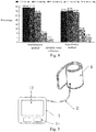
- the auscultatory method requires determining the strength of sound (strength of the pulsating sound) and the frequency of sound (whether the sound is a pulsating sound or noise). As shown in FIG.
- an electronic sphygmomanometer using the auscultatory method is unpopular due to high design difficulty and costs, and has poor anti-noise performance.
- the mercury sphygmomanometer (or other non-mercury media) using the auscultatory method is convenient, it is difficult for a user to measure his/her blood pressure by himself, and professional training is needed, because ears and eyes need to be highly synchronized during measurement so as to capture the sound change and corresponding pressure value. In addition, data cannot be automatically recorded.
- the oscillometric method is to determine the blood pressure value by measuring the amplitude of a pulse vibration wave with reference to a corresponding cuff pressure. Since the principle of the oscillometric method is easy to implement, electronic sphygmomanometers that use the oscillometric method to measure the blood pressure are mainstream products on the market. For example, most Omron electronic sphygmomanometers use the oscillometric method. Many studies have found through comparison that the oscillometric method sometimes has very poor accuracy. According to a report from Centers for Disease Control and Prevention of the United States, the measurement deviation of an Omron sphygmomanometer may be up to 16 mmHg. The low accuracy of the oscillometric method may be due to its measurement principle.
- the blood cannot flow before the pressure decreases to the systolic pressure, so that the user cannot hear the pulsating sound of blood flow.
- the vibration wave still exists, though with relatively small amplitude.
- the changing amplitude of the vibration wave is continuous before and after the systolic pressure and the diastolic pressure. This is different from the auscultatory method where no sound can be heard before a pulsating sound is produced.
- the vibration method can only establish an empirical association between the changing amplitude of the vibration wave and the blood pressure value by using a large number of individual samples.
- Such an average association established based on a large number of individual samples may not be effective when applied to a certain individual, resulting in that the error of blood pressure measurement is large for a certain proportion of population.
- the error is due to the deficiencies of the measurement principle, not the quality of the sphygmomanometer.
- An amplitude coefficient method is commonly used in the oscillometric method, as shown in FIG. 3 .
- normalization by comparing an amplitude value of a pulse wave vibration signal with a maximum amplitude value of the signal, and identifies the systolic pressure and the diastolic pressure by determining a normalization coefficient of the systolic pressure and the diastolic pressure, as shown in FIG. 3 .
- Am is the amplitude of the pulse wave corresponding to a mean pressure.
- Ad is the amplitude of the pulse wave corresponding to the diastolic blood pressure.
- As/Am is a normalized value of a systolic pressure Ps.
- Ad/Am is a normalized value of a diastolic pressure Pd.
- Pc is a cuff pressure. Horizontal coordinates represent that the pressure in the cuff continuously decreases during deflation.
- an amplitude coefficient of the systolic pressure is 0.46 to 0.64 and an amplitude coefficient of the diastolic pressure is 0.43 to 0.73. (from http://www.eccn.com/design_2011030416272188.htm). Because different sphygmomanometer manufacturers may use different amplitude coefficients, their measurement value may also differ greatly even if they all use a same oscillometric method. Each individual being measured may correspond to a different amplitude coefficient. However, the sphygmomanometer does not use different coefficients for different people.
- the measurement results of the electronic sphygmomanometer may be different from those obtained by doctors using the auscultatory method. Statistics shows that the measurement deviation of about 40% people may reach 5 mmHg or more, and the measurement deviation of about 15-20% people may reach 10 mmHg or more. This difference will affect the diagnosis and treatment of hypertension.
- the measurement results of different sphygmomanometer manufacturers for a same person may differ greatly. It is a big challenge for people whose blood pressure needs to be measured to determine the accuracy of the electronic sphygmomanometer. Medically, a user generally brings his/her own electronic sphygmomanometer to a doctor for comparison.
- sphygmomanometers designed using the two methods collect data and perform calculation by themselves, and present only the result to the user in a visual or auditory manner.
- the sphygmomanometer directly determines the blood pressure value, or the user directly determines the blood pressure value with eyes or ears. As a result, no original data is presented to assist the user in determining the blood pressure value.
- a technical problem to be resolved in the present invention is to provide a technical solution of blood pressure measurement that can enhance the precision and convenience of the blood pressure measurement, so that a patient can independently measure blood pressure and obtain an accurate measurement result.
- the present invention provides an auxiliary device for blood pressure measurement, including an audio collection part, an image collection part, and a terminal device, where the audio collection part is configured to collect a pulse sound signal during the blood pressure measurement and transmit the pulse sound signal to the terminal device; the image collection part is configured to collect a pressure image signal during the blood pressure measurement and transmit the pressure image signal to the terminal device; and the terminal device is configured to store the pulse sound signal and the pressure image signal.
- the terminal device is configured to store and synchronously play the pulse sound signal and synchronously display the pressure image signal.
- the terminal device includes a storage module, a display module, and a play module.
- the storage module is configured to store the pulse sound signal and the pressure image signal.
- the display module is configured to synchronously display the pressure image signal when the storage module stores the pressure image signal.
- the play module is configured to synchronously play the pulse sound signal when the storage module stores the pulse sound signal. The displaying of the pressure image signal and the playing of the pulse sound signal are synchronous.
- the terminal device is configured to: store the pulse sound signal and the pressure image signal, convert the pulse sound signal into pulse sound data, and synchronously display the pulse sound data and the pressure image signal.
- the terminal device includes a storage module, a processing module, and a display module.
- the storage module is configured to store the pulse sound signal and the pressure image signal.
- the processing module is configured to convert the pulse sound signal into the pulse sound data.
- the display module is configured to synchronously display the pulse sound data and the pressure image signal.
- the terminal device is configured to: store the pulse sound signal and the pressure image signal, convert the pulse sound signal into pulse sound data, convert the pressure image signal into pressure data, and obtain and display a blood pressure value according to the pulse sound data and the pressure data.
- the terminal device includes a storage module, a processing module, an operation module, and a display module.
- the storage module is configured to store the pulse sound signal and the pressure image signal.
- the processing module is configured to convert the pulse sound signal into the pulse sound data and convert the pressure image signal into the pressure data.
- the operation module is configured to obtain the blood pressure value according to the pulse sound data and the pressure data.
- the display module is configured to display the blood pressure value obtained by the operation module.
- the terminal device includes a storage module, a processing module, an operation module, and a display module.
- the storage module is configured to store the pulse sound signal and the pressure image signal.
- the processing module is configured to convert the pulse sound signal into the pulse sound data and convert the pressure image signal into the pressure data.
- the operation module is configured to obtain the blood pressure value according to the pulse sound data and the pressure data.
- the display module is configured to synchronously display the pulse sound signal and the pressure image signal and display the blood pressure value obtained by the operation module.
- the image collection part is disposed in the terminal device.
- the audio collection part includes an audio receiving part, an audio preprocessing part, and an audio transmission part.
- the audio preprocessing part is disposed in the audio receiving part, so that the pulse sound signal received by the audio receiving part is transmitted to the terminal device sequentially by using the audio preprocessing part, the audio transmission part, and a connecting part disposed at an end of the audio transmission part.
- the audio transmission part is an electrical wire.
- the audio collection part includes an audio receiving part, an audio preprocessing part, and an audio transmission part.
- the audio preprocessing part is disposed in the audio transmission part and is located at an end of the audio transmission part, so that the pulse sound signal received by the audio receiving part is transmitted to the audio preprocessing part by using the audio transmission part.
- the audio preprocessing part transmits the pulse sound signal to the terminal device by using a connecting part disposed at an end of the audio transmission part.
- the audio transmission part is an hollow pipe.
- the end of the audio transmission part is provided with the connecting part, so that the audio collection part can be electrically connected to the terminal device.
- the present invention further provides blood pressure measuring equipment, including a sphygmomanometer and the auxiliary device for blood pressure measurement according to any one of the foregoing descriptions.
- the image collection part records a screen output of an electronic sphygmomanometer or a pressure value corresponding to a mercury column on a mercury column sphygmomanometer by taking a video or a picture, so as to obtain a pressure image signal, and the audio collection part obtains a pulse sound of an upper arm, so that blood pressure can be determined by using an auscultatory method according to the recorded pressure value and the sound.
- the present invention improves the precision and convenience of blood pressure measurement, so that a vast majority of patients can independently measure blood pressure and obtain an accurate measurement result
- a working process of the auxiliary device for blood pressure measurement in the present invention includes the following:
- manual or automatic determining may be performed on the blood pressure value.
- This embodiment provides blood pressure measuring equipment, including a sphygmomanometer and an auxiliary device for blood pressure measurement.
- the auxiliary device for blood pressure measurement in this embodiment is mainly used to resolve a problem that a user cannot obtain original data when using an existing sphygmomanometer product for measurement, and consequently cannot independently measure blood pressure and obtain an accurate measurement result.
- an upper arm electronic sphygmomanometer (referring to FIG. 5 ) is used, including a host 1, an air pipeline 2, and a cuff bladder 3.
- the host 1 includes a button 11 and a touch display screen 12.
- the present invention is not limited to the upper arm electronic sphygmomanometer.
- a mercury sphygmomanometer, a wrist electronic sphygmomanometer, and other sphygmomanometers for different measured parts may alternatively be used.
- the auxiliary device for blood pressure measurement in this embodiment includes an audio collection part, an image collection part, and a terminal device.
- the audio collection part is configured to collect a pulse sound signal during the blood pressure measurement and transmit the pulse sound signal to the terminal device;
- the image collection part is configured to collect a pressure image signal during the blood pressure measurement and transmit the pressure image signal to the terminal device.
- the terminal device in this embodiment is configured to: store the pulse sound signal and the pressure image signal, synchronously play the pulse sound signal, and synchronously display the pressure image signal.
- the terminal device in this embodiment includes a storage module, a display module, and a play module.
- the storage module is configured to store the pulse sound signal and the pressure image signal.
- the display module is configured to synchronously display the pressure image signal when the storage module stores the pressure image signal.
- the play module is configured to synchronously play the pulse sound signal when the storage module stores the pulse sound signal.
- the displaying of the pressure image signal and the playing of the pulse sound signal are synchronous.
- the terminal device in this embodiment is a smartphone (referring to FIG. 6 ).
- the terminal device may alternatively be an intelligent device such as a computer, a tablet computer, a wristband, and a watch, or a wearable device.
- the image collection part in this embodiment is disposed in the terminal device, and may be a part capable of shooting an image, such as a camera.
- the audio collection part in this embodiment includes an audio receiving part, an audio preprocessing part, and an audio transmission part.
- An end of the audio transmission part is provided with a connecting part (for example, a headphone plug), so that the audio collection part can be electrically connected to the terminal device.
- the audio collection part in this embodiment is a stethoscope, including an auscultation head 4 and a microphone 5.
- the microphone 5 is inserted into the audio transmission part 6 and is located at an end of the audio transmission part 6.
- the headphone plug 7 is directly connected to the microphone 5.
- the audio transmission part 6 is a hollow pipe, such as a rubber pipe, so that the pulse sound signal received by the auscultation head 4 is transmitted to the microphone 5 by means of air vibration in the rubber pipe, and then the microphone 5 transmits the pulse sound signal to the terminal device by using the headphone plug.
- the microphone 5 may alternatively be disposed in the auscultation head.
- the audio transmission part 6 is an electrical wire, so that the pulse sound signal received by the auscultation head 4 is transmitted to the smartphone sequentially by using the microphone 5, the electrical wire, and the headphone plug 7.
- the stethoscope may alternatively be wirelessly connected to the smartphone.
- the pulse sound signal is transmitted to the smartphone by using Bluetooth.
- This embodiment provides blood pressure measuring equipment, including a sphygmomanometer and an auxiliary device for blood pressure measurement.
- the auxiliary device for blood pressure measurement in this embodiment is mainly used to resolve a problem that a user cannot obtain original data when using an existing sphygmomanometer product for measurement, and consequently cannot independently measure blood pressure and obtain an accurate measurement result.
- an upper arm electronic sphygmomanometer (referring to FIG. 5 ) is used, including a host 1, an air pipeline 2, and a cuff bladder 3.
- the host 1 includes a button 11 and a touch display screen 12.
- the present invention is not limited to the upper arm electronic sphygmomanometer.
- a mercury sphygmomanometer, a wrist electronic sphygmomanometer, and other sphygmomanometers for different measured parts may alternatively be used.
- the auxiliary device for blood pressure measurement in this embodiment includes an audio collection part, an image collection part, and a terminal device.
- the audio collection part is configured to collect a pulse sound signal during the blood pressure measurement and transmit the pulse sound signal to the terminal device;
- the image collection part is configured to collect a pressure image signal during the blood pressure measurement and transmit the pressure image signal to the terminal device.
- the terminal device in this embodiment is configured to: store the pulse sound signal and the pressure image signal, convert the pulse sound signal into pulse sound data, and synchronously display the pulse sound data and the pressure image signal.
- the terminal device in this embodiment includes a storage module, a processing module, and a display module.
- the storage module is configured to store the pulse sound signal and the pressure image signal.
- the processing module is configured to convert the pulse sound signal into the pulse sound data.
- the display module is configured to synchronously display the pulse sound data and the pressure image signal.
- the terminal device in this embodiment is a smartphone (referring to FIG. 6 ).
- the terminal device may alternatively be an intelligent device such as a computer, a tablet computer, a wristband, and a watch, or a wearable device.
- the image collection part in this embodiment is disposed in the terminal device, and may be a part capable of shooting an image, such as a camera.
- the audio collection part in this embodiment includes an audio receiving part, an audio preprocessing part, and an audio transmission part.
- An end of the audio transmission part is provided with a connecting part (for example, a headphone plug), so that the audio collection part can be electrically connected to the terminal device.
- the audio collection part in this embodiment is a stethoscope, including an auscultation head 4 and a microphone 5.
- the microphone 5 is inserted into the audio transmission part 6 and is located at an end of the audio transmission part 6.
- the headphone plug 7 is directly connected to the microphone 5.
- the audio transmission part 6 is a hollow pipe, such as a rubber pipe, so that the pulse sound signal received by the auscultation head 4 is transmitted to the microphone 5 by means of air vibration in the rubber pipe, and then the microphone 5 transmits the pulse sound signal to the terminal device by using the headphone plug.
- the microphone 5 may alternatively be disposed in the auscultation head.
- the audio transmission part 6 is an electrical wire, so that the pulse sound signal received by the auscultation head 4 is transmitted to the smartphone sequentially by using the microphone 5, the electrical wire, and the headphone plug 7.
- the stethoscope may alternatively be wirelessly connected to the smartphone.
- the pulse sound signal is transmitted to the smartphone by using Bluetooth.
- This embodiment provides blood pressure measuring equipment, including a sphygmomanometer and an auxiliary device for blood pressure measurement.
- the auxiliary device for blood pressure measurement in this embodiment is mainly used to resolve a problem that a user cannot obtain original data when using an existing sphygmomanometer product for measurement, and consequently cannot independently measure blood pressure and obtain an accurate measurement result.
- an upper arm electronic sphygmomanometer (referring to FIG. 5 ) is used, including a host 1, an air pipeline 2, and a cuff bladder 3.
- the host 1 includes a button 11 and a touch display screen 12.
- the present invention is not limited to the upper arm electronic sphygmomanometer.
- a mercury sphygmomanometer, a wrist electronic sphygmomanometer, and other sphygmomanometers for different measured parts may alternatively be used.
- the auxiliary device for blood pressure measurement in this embodiment includes an audio collection part, an image collection part, and a terminal device.
- the audio collection part is configured to collect a pulse sound signal during the blood pressure measurement and transmit the pulse sound signal to the terminal device;
- the image collection part is configured to collect a pressure image signal during the blood pressure measurement and transmit the pressure image signal to the terminal device.
- the terminal device in this embodiment is configured to: store the pulse sound signal and the pressure image signal, convert the pulse sound signal into pulse sound data, convert the pressure image signal into pressure data, and obtain and display a blood pressure value according to the pulse sound data and the pressure data.
- the terminal device in this embodiment includes a storage module, a processing module, an operation module, and a display module.
- the storage module is configured to store the pulse sound signal and the pressure image signal.
- the processing module is configured to convert the pulse sound signal into the pulse sound data and convert the pressure image signal into the pressure data.
- the operation module is configured to obtain the blood pressure value according to the pulse sound data and the pressure data.
- the display module is configured to display the blood pressure value obtained by the operation module.
- the terminal device in this embodiment is a smartphone (referring to FIG. 6 ).
- the terminal device may alternatively be an intelligent device such as a computer, a tablet computer, a wristband, and a watch, or a wearable device.
- the image collection part in this embodiment is disposed in the terminal device, and may be a part capable of shooting an image, such as a camera.
- the audio collection part in this embodiment includes an audio receiving part, an audio preprocessing part, and an audio transmission part.
- An end of the audio transmission part is provided with a connecting part (for example, a headphone plug), so that the audio collection part can be electrically connected to the terminal device.
- the audio collection part in this embodiment is a stethoscope, including an auscultation head 4 and a microphone 5.
- the microphone 5 is inserted into the audio transmission part 6 and is located at an end of the audio transmission part 6.
- the headphone plug 7 is directly connected to the microphone 5.
- the audio transmission part 6 is a hollow pipe, such as a rubber pipe, so that the pulse sound signal received by the auscultation head 4 is transmitted to the microphone 5 by means of air vibration in the rubber pipe, and then the microphone 5 transmits the pulse sound signal to the terminal device by using the headphone plug.
- the microphone 5 may alternatively be disposed in the auscultation head.
- the audio transmission part 6 is an electrical wire, so that the pulse sound signal received by the auscultation head 4 is transmitted to the smartphone sequentially by using the microphone 5, the electrical wire, and the headphone plug 7.
- the stethoscope may alternatively be wirelessly connected to the smartphone.
- the pulse sound signal is transmitted to the smartphone by using Bluetooth.
- This embodiment provides blood pressure measuring equipment, including a sphygmomanometer and an auxiliary device for blood pressure measurement.
- the auxiliary device for blood pressure measurement in this embodiment is mainly used to resolve a problem that a user cannot obtain original data when using an existing sphygmomanometer product for measurement, and consequently cannot independently measure blood pressure and obtain an accurate measurement result.
- an upper arm electronic sphygmomanometer (referring to FIG. 5 ) is used, including a host 1, an air pipeline 2, and a cuff bladder 3.
- the host 1 includes a button 11 and a touch display screen 12.
- the present invention is not limited to the upper arm electronic sphygmomanometer.
- a mercury sphygmomanometer, a wrist electronic sphygmomanometer, and other sphygmomanometers for different measured parts may alternatively be used.
- the auxiliary device for blood pressure measurement in this embodiment includes an audio collection part, an image collection part, and a terminal device.
- the audio collection part is configured to collect a pulse sound signal during the blood pressure measurement and transmit the pulse sound signal to the terminal device;
- the image collection part is configured to collect a pressure image signal during the blood pressure measurement and transmit the pressure image signal to the terminal device.
- the terminal device in this embodiment is configured to: store the pulse sound signal and the pressure image signal, convert the pulse sound signal into pulse sound data, convert the pressure image signal into pressure data, and obtain and display a blood pressure value according to the pulse sound data and the pressure data.
- the terminal device in this embodiment includes a storage module, a processing module, an operation module, and a display module.
- the storage module is configured to store the pulse sound signal and the pressure image signal.
- the processing module is configured to convert the pulse sound signal into the pulse sound data and convert the pressure image signal into the pressure data.
- the operation module is configured to obtain the blood pressure value according to the pulse sound data and the pressure data.
- the display module is configured to synchronously display the pulse sound signal and the pressure image signal and display the blood pressure value obtained by the operation module.
- the terminal device in this embodiment is a smartphone (referring to FIG. 6 ).
- the terminal device may alternatively be an intelligent device such as a computer, a tablet computer, a wristband, and a watch, or a wearable device.
- the image collection part in this embodiment is disposed in the terminal device, and may be a part capable of shooting an image, such as a camera.
- the audio collection part in this embodiment includes an audio receiving part, an audio preprocessing part, and an audio transmission part.
- An end of the audio transmission part is provided with a connecting part (for example, a headphone plug), so that the audio collection part can be electrically connected to the terminal device.
- the audio collection part in this embodiment is a stethoscope, including an auscultation head 4 and a microphone 5.
- the microphone 5 is inserted into the audio transmission part 6 and is located at an end of the audio transmission part 6.
- the headphone plug 7 is directly connected to the microphone 5.
- the audio transmission part 6 is a hollow pipe, such as a rubber pipe, so that the pulse sound signal received by the auscultation head 4 is transmitted to the microphone 5 by means of air vibration in the rubber pipe, and then the microphone 5 transmits the pulse sound signal to the terminal device by using the headphone plug.
- the microphone 5 may alternatively be disposed in the auscultation head.
- the audio transmission part 6 is an electrical wire, so that the pulse sound signal received by the auscultation head 4 is transmitted to the smartphone sequentially by using the microphone 5, the electrical wire, and the headphone plug 7.
- the stethoscope may alternatively be wirelessly connected to the smartphone.
- the pulse sound signal is transmitted to the smartphone by using Bluetooth.
- Functions such as storage, processing, operation, and displaying of the terminal device in the embodiments may all be implemented by an application (APP) installed in the terminal device.
- APP application
- a process of using the blood pressure measuring equipment in the embodiments is as follows: First, the headphone plug of the stethoscope is plugged into the smartphone during use.
- a measuring process of the sphygmomanometer is the same as that of an ordinary sphygmomanometer.
- the sphygmomanometer controls inflation and deflation.
- the stethoscope is fixed inside the cuff bladder of the sphygmomanometer and is closely attached to a brachial artery to collect an auscultatory sound (a pulse sound).
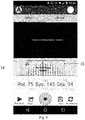
- the APP in the smartphone is started. An operating interface of the APP is shown in FIG. 8 .
- the camera on the smartphone is aligned with a display screen of the electronic sphygmomanometer and starts recording an image on the display screen of the sphygmomanometer and a sound in the stethoscope during blood pressure measurement.
- the APP in the smartphone processes image data and sound data, for example, displays the amplitude of the strength of the sound, obtains a pressure reading according to image identification, and further determines the blood pressure.
- the APP in the smartphone may further perform further data analysis: displaying the sound data and the pressure image signal on a same timeline.
- a vertical line 14 on the left of the figure marks a time point that corresponds to a systolic pressure and is determined according to an auscultatory method.
- a vertical line 15 on the right of the figure marks a time point corresponding to a diastolic pressure. Therefore, images that can correspond to the time point and pressure values displayed on the images are the systolic pressure and the diastolic pressure.
- a vertical line 16 in the middle moves with a playing progress of the sound. An amplitude curve of the strength of the sound that the vertical line 16 passes through helps the user more accurately determine the sound heard by ears.
- a graphical audio signal of the APP may be in a time domain, or in a frequency domain, or both.
- the graph is not limited to a line graph, and may be a bar graph or the like. It may be further set that operations such as pausing, continuing, and setting of loop playback between two time points can be performed at any time in a playback process of the sound.
- the user may manually determine, based on a result that the APP graphically displays the pulse sound data and the pressure image signal on a same timeline, the blood pressure value by using the auscultatory method.
- the APP may alternatively calculate, according to the pressure data, the blood pressure value by using the oscillometric method.
- Parameters for example, C1 and C2 in an amplitude parameter method
- it may be set, for measurement at a time, to input a blood pressure value determined to be accurate (for example, the blood pressure value manually determined by using the auscultatory method).
- An exclusive APP is used to compare the input blood pressure value with a blood pressure value determined by using the oscillometric method and adjust the parameters according to a comparison result, so that the parameters can be simply adjusted without professionals.
- parameters for example, C1 and C2 used in the oscillometric method may be automatically calibrated based on the blood pressure value determined by using the auscultatory method.
- This calibration may be set to be periodic, for example, set to automatic calibration after a time period or times.
- Parameter modification is calibration for an individual situation, so that the measurement precision is generally higher than a direct reading on an ordinary electronic sphygmomanometer.
- a relatively accurate blood pressure value can be obtained without using the stethoscope (the auscultatory method is not used to determine the blood pressure value).
- the blood pressure measuring equipment in the embodiments is the same as the ordinary electronic sphygmomanometer. Only one click is required to start.
- the sphygmomanometer automatically performs inflation and deflation to the cuff bladder and synchronously records measured data. After measurement, a blood pressure value determined by using the oscillometric method and/or the auscultatory method is automatically displayed.
- the recorded pressure image signal (or the pressure data) and sound data may be played back on the terminal device (for example, the smartphone in the embodiments), to manually determine the blood pressure value by using the auscultatory method.
Abstract
Description
- The present invention relates to the field of blood pressure monitoring, and in particular, to an auxiliary device for blood pressure measurement and blood pressure measuring equipment.
- Currently, sphygmomanometers available on the market are mainly based on two measurement methods: an auscultatory method and an oscillometric method.
- The auscultatory method is the main method used in clinical medication. Mercury sphygmomanometers used by doctors are designed according to the auscultatory method. The auscultatory method is to determine a blood pressure value by using a stethoscope to hear a flowing sound of the blood in the brachial artery with reference to a corresponding pressure when a cuff bladder of the sphygmomanometer is deflated, as shown in
FIG. 1 . When a pulsating sound is heard in the stethoscope for the first time, the height of the mercury column is the systolic pressure. When the pulsating sound suddenly becomes weak or cannot be heard, the height of the mercury column is the diastolic pressure. For its high measurement accuracy, the auscultatory method is medically referred to as a gold standard for blood pressure measurement. Generally, studies on the measurement accuracy of sphygmomanometers of other types are carried out in comparison with the auscultatory method using a mercury sphygmomanometer. However, the application of the auscultatory method to an electronic sphygmomanometer still has limitations. This is mainly because the capability of electronic devices to distinguish sounds is weaker than human ears in some respects. The auscultatory method requires determining the strength of sound (strength of the pulsating sound) and the frequency of sound (whether the sound is a pulsating sound or noise). As shown inFIG. 2 , an electronic sphygmomanometer using the auscultatory method is unpopular due to high design difficulty and costs, and has poor anti-noise performance. Although the mercury sphygmomanometer (or other non-mercury media) using the auscultatory method is convenient, it is difficult for a user to measure his/her blood pressure by himself, and professional training is needed, because ears and eyes need to be highly synchronized during measurement so as to capture the sound change and corresponding pressure value. In addition, data cannot be automatically recorded. - The oscillometric method is to determine the blood pressure value by measuring the amplitude of a pulse vibration wave with reference to a corresponding cuff pressure. Since the principle of the oscillometric method is easy to implement, electronic sphygmomanometers that use the oscillometric method to measure the blood pressure are mainstream products on the market. For example, most Omron electronic sphygmomanometers use the oscillometric method. Many studies have found through comparison that the oscillometric method sometimes has very poor accuracy. According to a report from Centers for Disease Control and Prevention of the United States, the measurement deviation of an Omron sphygmomanometer may be up to 16 mmHg. The low accuracy of the oscillometric method may be due to its measurement principle. In the auscultatory method, during the deflation of the cuff bladder, the blood cannot flow before the pressure decreases to the systolic pressure, so that the user cannot hear the pulsating sound of blood flow. However, in the oscillometric method, before the blood pressure decreases to the systolic pressure, the vibration wave still exists, though with relatively small amplitude. During the deflation of the cuff or the decrease in pressure of the bladder, the changing amplitude of the vibration wave is continuous before and after the systolic pressure and the diastolic pressure. This is different from the auscultatory method where no sound can be heard before a pulsating sound is produced. Therefore, the vibration method can only establish an empirical association between the changing amplitude of the vibration wave and the blood pressure value by using a large number of individual samples. Such an average association established based on a large number of individual samples may not be effective when applied to a certain individual, resulting in that the error of blood pressure measurement is large for a certain proportion of population. The error is due to the deficiencies of the measurement principle, not the quality of the sphygmomanometer.
- An amplitude coefficient method, or referred to as 'normalization method', is commonly used in the oscillometric method, as shown in
FIG. 3 . According to this method, normalization by comparing an amplitude value of a pulse wave vibration signal with a maximum amplitude value of the signal, and identifies the systolic pressure and the diastolic pressure by determining a normalization coefficient of the systolic pressure and the diastolic pressure, as shown inFIG. 3 . As is the amplitude of the pulse wave corresponding to the systolic pressure. Am is the amplitude of the pulse wave corresponding to a mean pressure. Ad is the amplitude of the pulse wave corresponding to the diastolic blood pressure. As/Am is a normalized value of a systolic pressure Ps. Ad/Am is a normalized value of a diastolic pressure Pd. Pc is a cuff pressure. Horizontal coordinates represent that the pressure in the cuff continuously decreases during deflation. As/Am=C1, and Ad/Am=C2, respectively corresponding to the positions of the systolic pressure and the diastolic pressure. According to a measured amplitude value of the pulse wave and a corresponding static pressure, the systolic pressure Ps, the diastolic pressure Pd, and the mean pressure Pm can be obtained. Generally, an amplitude coefficient of the systolic pressure is 0.46 to 0.64 and an amplitude coefficient of the diastolic pressure is 0.43 to 0.73. (from http://www.eccn.com/design_2011030416272188.htm). Because different sphygmomanometer manufacturers may use different amplitude coefficients, their measurement value may also differ greatly even if they all use a same oscillometric method. Each individual being measured may correspond to a different amplitude coefficient. However, the sphygmomanometer does not use different coefficients for different people. - For different people, the measurement results of the electronic sphygmomanometer may be different from those obtained by doctors using the auscultatory method. Statistics shows that the measurement deviation of about 40% people may reach 5 mmHg or more, and the measurement deviation of about 15-20% people may reach 10 mmHg or more. This difference will affect the diagnosis and treatment of hypertension. In addition, because different electronic sphygmomanometer manufacturers use different algorithms, the measurement results of different sphygmomanometer manufacturers for a same person may differ greatly. It is a big challenge for people whose blood pressure needs to be measured to determine the accuracy of the electronic sphygmomanometer. Medically, a user generally brings his/her own electronic sphygmomanometer to a doctor for comparison. Such an operation is inconvenient. In addition, because the blood pressure of a human body is fluctuant, when a reading of the electronic sphygmomanometer is different from a reading measured by the doctor, interference is generated and the determination of the accuracy of the electronic sphygmomanometer is affected. As shown in
FIG 4 , to determine whether an electronic sphygmomanometer can accurately measure the blood pressure of a particular user, two methods (the oscillometric method used by the electronic sphygmomanometer and the auscultatory method used by the doctor) need to be separately used to measure the blood pressure of the particular user. Then, the measurement results are recorded, and a difference between the measurement results is calculated. - Currently, sphygmomanometers designed using the two methods collect data and perform calculation by themselves, and present only the result to the user in a visual or auditory manner. During the blood pressure measurement, either the sphygmomanometer directly determines the blood pressure value, or the user directly determines the blood pressure value with eyes or ears. As a result, no original data is presented to assist the user in determining the blood pressure value.
- In view of the disadvantages in the prior art, a technical problem to be resolved in the present invention is to provide a technical solution of blood pressure measurement that can enhance the precision and convenience of the blood pressure measurement, so that a patient can independently measure blood pressure and obtain an accurate measurement result.
- To achieve the foregoing objective, the present invention provides an auxiliary device for blood pressure measurement, including an audio collection part, an image collection part, and a terminal device, where
the audio collection part is configured to collect a pulse sound signal during the blood pressure measurement and transmit the pulse sound signal to the terminal device;
the image collection part is configured to collect a pressure image signal during the blood pressure measurement and transmit the pressure image signal to the terminal device; and
the terminal device is configured to store the pulse sound signal and the pressure image signal. - In a preferred embodiment of the present invention, the terminal device is configured to store and synchronously play the pulse sound signal and synchronously display the pressure image signal.
- Further, the terminal device includes a storage module, a display module, and a play module. The storage module is configured to store the pulse sound signal and the pressure image signal. The display module is configured to synchronously display the pressure image signal when the storage module stores the pressure image signal. The play module is configured to synchronously play the pulse sound signal when the storage module stores the pulse sound signal. The displaying of the pressure image signal and the playing of the pulse sound signal are synchronous.
- In another preferred embodiment of the present invention, the terminal device is configured to: store the pulse sound signal and the pressure image signal, convert the pulse sound signal into pulse sound data, and synchronously display the pulse sound data and the pressure image signal.
- Further, the terminal device includes a storage module, a processing module, and a display module. The storage module is configured to store the pulse sound signal and the pressure image signal. The processing module is configured to convert the pulse sound signal into the pulse sound data. The display module is configured to synchronously display the pulse sound data and the pressure image signal.
- In still another preferred embodiment of the present invention, the terminal device is configured to: store the pulse sound signal and the pressure image signal, convert the pulse sound signal into pulse sound data, convert the pressure image signal into pressure data, and obtain and display a blood pressure value according to the pulse sound data and the pressure data.
- Further, the terminal device includes a storage module, a processing module, an operation module, and a display module. The storage module is configured to store the pulse sound signal and the pressure image signal. The processing module is configured to convert the pulse sound signal into the pulse sound data and convert the pressure image signal into the pressure data. The operation module is configured to obtain the blood pressure value according to the pulse sound data and the pressure data. The display module is configured to display the blood pressure value obtained by the operation module.
- Preferably, the terminal device includes a storage module, a processing module, an operation module, and a display module. The storage module is configured to store the pulse sound signal and the pressure image signal. The processing module is configured to convert the pulse sound signal into the pulse sound data and convert the pressure image signal into the pressure data. The operation module is configured to obtain the blood pressure value according to the pulse sound data and the pressure data. The display module is configured to synchronously display the pulse sound signal and the pressure image signal and display the blood pressure value obtained by the operation module.
- Further, the image collection part is disposed in the terminal device.
- Further, the audio collection part includes an audio receiving part, an audio preprocessing part, and an audio transmission part. The audio preprocessing part is disposed in the audio receiving part, so that the pulse sound signal received by the audio receiving part is transmitted to the terminal device sequentially by using the audio preprocessing part, the audio transmission part, and a connecting part disposed at an end of the audio transmission part.
- Preferably, the audio transmission part is an electrical wire.
- Further, the audio collection part includes an audio receiving part, an audio preprocessing part, and an audio transmission part. The audio preprocessing part is disposed in the audio transmission part and is located at an end of the audio transmission part, so that the pulse sound signal received by the audio receiving part is transmitted to the audio preprocessing part by using the audio transmission part. The audio preprocessing part transmits the pulse sound signal to the terminal device by using a connecting part disposed at an end of the audio transmission part.
- Preferably, the audio transmission part is an hollow pipe.
- Further, the end of the audio transmission part is provided with the connecting part, so that the audio collection part can be electrically connected to the terminal device.
- The present invention further provides blood pressure measuring equipment, including a sphygmomanometer and the auxiliary device for blood pressure measurement according to any one of the foregoing descriptions. In the auxiliary device for blood pressure measurement in the present invention, the image collection part records a screen output of an electronic sphygmomanometer or a pressure value corresponding to a mercury column on a mercury column sphygmomanometer by taking a video or a picture, so as to obtain a pressure image signal, and the audio collection part obtains a pulse sound of an upper arm, so that blood pressure can be determined by using an auscultatory method according to the recorded pressure value and the sound. Compared with the prior art, the present invention improves the precision and convenience of blood pressure measurement, so that a vast majority of patients can independently measure blood pressure and obtain an accurate measurement result
- A working process of the auxiliary device for blood pressure measurement in the present invention includes the following:
- (1) When a user uses an electronic sphygmomanometer, an auscultatory sound (Korotkoff's sound), that is, a pulse sound, is collected by using the audio collection part and the pulse sound is recorded by the terminal device.
A main difference between the oscillometric method and the auscultatory method in blood pressure measurement is that blood pressure is calculated according to pressure fluctuation in the oscillometric method but blood pressure is directly determined according to an auscultatory sound in the auscultatory method. If the sound is recorded by the terminal device when the electronic sphygmomanometer is used for measurement, the blood pressure can be determined according to the sound recorded by the terminal device. - (2) The pressure image signal is shot by using a shooting function of the image collection part, such as a camera, in the terminal device. The pressure image signal or the pressure data is recorded by the terminal device.
In the auscultatory method, corresponding cuff pressures when an auscultatory sound appears and disappears need to be found to determine the blood pressure. During measurement, the cuff pressure is generally displayed on a screen of the sphygmomanometer in real time. The pressure image signal (that is, an image displaying the pressure data) of the sphygmomanometer during measurement can be shot by using a shooting function of the terminal device. Since the sound is recorded during shooting, the shot pressure image signal that is displayed on the sphygmomanometer and the auscultatory sound recorded by a smartphone are synchronous. - (3) The auscultatory sound is graphically displayed.
The auscultatory sound may be graphically displayed on a screen of the terminal device to assist in determining positions where the auscultatory sound appears and disappears. - (4) Image identification of a pressure number is implemented by using the terminal device. A pressure value may be directly extracted by using an image identification technology from an image that displays the pressure data and is shot by the image collection part in the terminal device. In this way, a correspondence between the pressure and the sound is obtained.
- (5) Manual or automatic determining is performed on the blood pressure value on the terminal device.
- For data of the pressure and sound that is recorded by the terminal device, manual or automatic determining may be performed on the blood pressure value.
- Technical effects of the present invention include the following:
- (1) The audio collection part collects the pulse sound signal, the image collection part collects the pressure image signal, and the terminal device stores and synchronously plays the pulse sound signal and the pressure image signal, so that a user can independently obtain a pressure value according to the pulse sound signal that is heard and the pressure data in the pressure image signal that is seen.
- (2) The audio collection part collects the pulse sound signal, the image collection part collects the pressure image signal, and the terminal device stores the pulse sound signal and the pressure image signal, converts the pulse sound signal into the pulse sound data, and synchronously displays the pulse sound data and the pressure image signal, so that a the user can independently obtain a pressure value according to the pulse sound data and the pressure data in the pressure image signal that are seen.
- (3) The audio collection part collects the pulse sound signal, the image collection part collects the pressure image signal, and the terminal device stores the pulse sound signal and the pressure image signal, converts the pulse sound signal into the pulse sound data, converts the pressure image signal into the pressure data, and obtains and displays the blood pressure value according to the pulse sound data and the pressure data, so that a user can directly learn the blood pressure value according to a result displayed on the terminal device or independently obtain a pressure value according to the pulse sound data and the pressure data that are seen.
- (4) A blood pressure value measured by an ordinary electronic sphygmomanometer is obtained by using the audio collection part and the terminal device according to the auscultatory method. The auscultatory method is a golden standard of noninvasive blood pressure measurement. Therefore, the obtained blood pressure value may be used to evaluate the measurement accuracy of a particular electronic sphygmomanometer on a particular user.
- (5) The auxiliary device for blood pressure measurement in the present invention is applicable to an electronic sphygmomanometer, a sphygmomanometer, and a mercury sphygmomanometer taking millimeter of mercury as a unit.
- The following further describes the concepts, specific structures, and generated technical effects of the present invention with reference to the accompanying drawings, so as to fully understand the objectives, features, and effects of the present invention.
-
-
FIG. 1 is a diagram of a correspondence between the amplitude of a pulse wave and a cuff pressure in an oscillometric method; -
FIG. 2 is a diagram of a small pulse generated in a cuff; -
FIG. 3 is a line graph of a normalized value; -
FIG. 4 is a control diagram of an absolute value difference between an auscultatory method and an oscillometric method among different blood pressure measuring equipment; -
FIG. 5 is a schematic diagram of an upper arm electronic sphygmomanometer according to a specific embodiment of the present invention; -
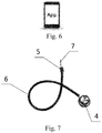
FIG. 6 is a schematic diagram of a smartphone according to a specific embodiment of the present invention; -
FIG. 7 is a schematic diagram of an audio collection part according to a specific embodiment of the present invention; and -
FIG. 8 is a schematic diagram of an operating interface of an APP according toEmbodiment 3 of the present invention. - This embodiment provides blood pressure measuring equipment, including a sphygmomanometer and an auxiliary device for blood pressure measurement. The auxiliary device for blood pressure measurement in this embodiment is mainly used to resolve a problem that a user cannot obtain original data when using an existing sphygmomanometer product for measurement, and consequently cannot independently measure blood pressure and obtain an accurate measurement result. In this embodiment, an upper arm electronic sphygmomanometer (referring to
FIG. 5 ) is used, including ahost 1, anair pipeline 2, and acuff bladder 3. Thehost 1 includes abutton 11 and atouch display screen 12. However, the present invention is not limited to the upper arm electronic sphygmomanometer. A mercury sphygmomanometer, a wrist electronic sphygmomanometer, and other sphygmomanometers for different measured parts may alternatively be used. - The auxiliary device for blood pressure measurement in this embodiment includes an audio collection part, an image collection part, and a terminal device. The audio collection part is configured to collect a pulse sound signal during the blood pressure measurement and transmit the pulse sound signal to the terminal device; the image collection part is configured to collect a pressure image signal during the blood pressure measurement and transmit the pressure image signal to the terminal device.
- The terminal device in this embodiment is configured to: store the pulse sound signal and the pressure image signal, synchronously play the pulse sound signal, and synchronously display the pressure image signal. Specifically, the terminal device in this embodiment includes a storage module, a display module, and a play module. The storage module is configured to store the pulse sound signal and the pressure image signal. The display module is configured to synchronously display the pressure image signal when the storage module stores the pressure image signal. The play module is configured to synchronously play the pulse sound signal when the storage module stores the pulse sound signal. The displaying of the pressure image signal and the playing of the pulse sound signal are synchronous. The terminal device in this embodiment is a smartphone (referring to
FIG. 6 ). In other embodiments, the terminal device may alternatively be an intelligent device such as a computer, a tablet computer, a wristband, and a watch, or a wearable device. - The image collection part in this embodiment is disposed in the terminal device, and may be a part capable of shooting an image, such as a camera. The audio collection part in this embodiment includes an audio receiving part, an audio preprocessing part, and an audio transmission part. An end of the audio transmission part is provided with a connecting part (for example, a headphone plug), so that the audio collection part can be electrically connected to the terminal device. Specifically, as shown in
FIG. 7 , the audio collection part in this embodiment is a stethoscope, including anauscultation head 4 and amicrophone 5. Themicrophone 5 is inserted into theaudio transmission part 6 and is located at an end of theaudio transmission part 6. Theheadphone plug 7 is directly connected to themicrophone 5. In addition, theaudio transmission part 6 is a hollow pipe, such as a rubber pipe, so that the pulse sound signal received by theauscultation head 4 is transmitted to themicrophone 5 by means of air vibration in the rubber pipe, and then themicrophone 5 transmits the pulse sound signal to the terminal device by using the headphone plug. - In other embodiments, the
microphone 5 may alternatively be disposed in the auscultation head. In this case, theaudio transmission part 6 is an electrical wire, so that the pulse sound signal received by theauscultation head 4 is transmitted to the smartphone sequentially by using themicrophone 5, the electrical wire, and theheadphone plug 7. - In other embodiments, the stethoscope may alternatively be wirelessly connected to the smartphone. For example, the pulse sound signal is transmitted to the smartphone by using Bluetooth.
- This embodiment provides blood pressure measuring equipment, including a sphygmomanometer and an auxiliary device for blood pressure measurement. The auxiliary device for blood pressure measurement in this embodiment is mainly used to resolve a problem that a user cannot obtain original data when using an existing sphygmomanometer product for measurement, and consequently cannot independently measure blood pressure and obtain an accurate measurement result. In this embodiment, an upper arm electronic sphygmomanometer (referring to
FIG. 5 ) is used, including ahost 1, anair pipeline 2, and acuff bladder 3. Thehost 1 includes abutton 11 and atouch display screen 12. However, the present invention is not limited to the upper arm electronic sphygmomanometer. A mercury sphygmomanometer, a wrist electronic sphygmomanometer, and other sphygmomanometers for different measured parts may alternatively be used. - The auxiliary device for blood pressure measurement in this embodiment includes an audio collection part, an image collection part, and a terminal device. The audio collection part is configured to collect a pulse sound signal during the blood pressure measurement and transmit the pulse sound signal to the terminal device; the image collection part is configured to collect a pressure image signal during the blood pressure measurement and transmit the pressure image signal to the terminal device.
- The terminal device in this embodiment is configured to: store the pulse sound signal and the pressure image signal, convert the pulse sound signal into pulse sound data, and synchronously display the pulse sound data and the pressure image signal. Specifically, the terminal device in this embodiment includes a storage module, a processing module, and a display module. The storage module is configured to store the pulse sound signal and the pressure image signal. The processing module is configured to convert the pulse sound signal into the pulse sound data. The display module is configured to synchronously display the pulse sound data and the pressure image signal. The terminal device in this embodiment is a smartphone (referring to
FIG. 6 ). In other embodiments, the terminal device may alternatively be an intelligent device such as a computer, a tablet computer, a wristband, and a watch, or a wearable device. - The image collection part in this embodiment is disposed in the terminal device, and may be a part capable of shooting an image, such as a camera. The audio collection part in this embodiment includes an audio receiving part, an audio preprocessing part, and an audio transmission part. An end of the audio transmission part is provided with a connecting part (for example, a headphone plug), so that the audio collection part can be electrically connected to the terminal device. Specifically, as shown in
FIG. 7 , the audio collection part in this embodiment is a stethoscope, including anauscultation head 4 and amicrophone 5. Themicrophone 5 is inserted into theaudio transmission part 6 and is located at an end of theaudio transmission part 6. Theheadphone plug 7 is directly connected to themicrophone 5. In addition, theaudio transmission part 6 is a hollow pipe, such as a rubber pipe, so that the pulse sound signal received by theauscultation head 4 is transmitted to themicrophone 5 by means of air vibration in the rubber pipe, and then themicrophone 5 transmits the pulse sound signal to the terminal device by using the headphone plug. - In other embodiments, the
microphone 5 may alternatively be disposed in the auscultation head. In this case, theaudio transmission part 6 is an electrical wire, so that the pulse sound signal received by theauscultation head 4 is transmitted to the smartphone sequentially by using themicrophone 5, the electrical wire, and theheadphone plug 7. - In other embodiments, the stethoscope may alternatively be wirelessly connected to the smartphone. For example, the pulse sound signal is transmitted to the smartphone by using Bluetooth.
- This embodiment provides blood pressure measuring equipment, including a sphygmomanometer and an auxiliary device for blood pressure measurement. The auxiliary device for blood pressure measurement in this embodiment is mainly used to resolve a problem that a user cannot obtain original data when using an existing sphygmomanometer product for measurement, and consequently cannot independently measure blood pressure and obtain an accurate measurement result. In this embodiment, an upper arm electronic sphygmomanometer (referring to
FIG. 5 ) is used, including ahost 1, anair pipeline 2, and acuff bladder 3. Thehost 1 includes abutton 11 and atouch display screen 12. However, the present invention is not limited to the upper arm electronic sphygmomanometer. A mercury sphygmomanometer, a wrist electronic sphygmomanometer, and other sphygmomanometers for different measured parts may alternatively be used. - The auxiliary device for blood pressure measurement in this embodiment includes an audio collection part, an image collection part, and a terminal device. The audio collection part is configured to collect a pulse sound signal during the blood pressure measurement and transmit the pulse sound signal to the terminal device; the image collection part is configured to collect a pressure image signal during the blood pressure measurement and transmit the pressure image signal to the terminal device.
- The terminal device in this embodiment is configured to: store the pulse sound signal and the pressure image signal, convert the pulse sound signal into pulse sound data, convert the pressure image signal into pressure data, and obtain and display a blood pressure value according to the pulse sound data and the pressure data. Specifically, the terminal device in this embodiment includes a storage module, a processing module, an operation module, and a display module. The storage module is configured to store the pulse sound signal and the pressure image signal. The processing module is configured to convert the pulse sound signal into the pulse sound data and convert the pressure image signal into the pressure data. The operation module is configured to obtain the blood pressure value according to the pulse sound data and the pressure data. The display module is configured to display the blood pressure value obtained by the operation module. The terminal device in this embodiment is a smartphone (referring to
FIG. 6 ). In other embodiments, the terminal device may alternatively be an intelligent device such as a computer, a tablet computer, a wristband, and a watch, or a wearable device. - The image collection part in this embodiment is disposed in the terminal device, and may be a part capable of shooting an image, such as a camera. The audio collection part in this embodiment includes an audio receiving part, an audio preprocessing part, and an audio transmission part. An end of the audio transmission part is provided with a connecting part (for example, a headphone plug), so that the audio collection part can be electrically connected to the terminal device. Specifically, as shown in
FIG. 7 , the audio collection part in this embodiment is a stethoscope, including anauscultation head 4 and amicrophone 5. Themicrophone 5 is inserted into theaudio transmission part 6 and is located at an end of theaudio transmission part 6. Theheadphone plug 7 is directly connected to themicrophone 5. In addition, theaudio transmission part 6 is a hollow pipe, such as a rubber pipe, so that the pulse sound signal received by theauscultation head 4 is transmitted to themicrophone 5 by means of air vibration in the rubber pipe, and then themicrophone 5 transmits the pulse sound signal to the terminal device by using the headphone plug. - In other embodiments, the
microphone 5 may alternatively be disposed in the auscultation head. In this case, theaudio transmission part 6 is an electrical wire, so that the pulse sound signal received by theauscultation head 4 is transmitted to the smartphone sequentially by using themicrophone 5, the electrical wire, and theheadphone plug 7. - In other embodiments, the stethoscope may alternatively be wirelessly connected to the smartphone. For example, the pulse sound signal is transmitted to the smartphone by using Bluetooth.
- This embodiment provides blood pressure measuring equipment, including a sphygmomanometer and an auxiliary device for blood pressure measurement. The auxiliary device for blood pressure measurement in this embodiment is mainly used to resolve a problem that a user cannot obtain original data when using an existing sphygmomanometer product for measurement, and consequently cannot independently measure blood pressure and obtain an accurate measurement result. In this embodiment, an upper arm electronic sphygmomanometer (referring to
FIG. 5 ) is used, including ahost 1, anair pipeline 2, and acuff bladder 3. Thehost 1 includes abutton 11 and atouch display screen 12. However, the present invention is not limited to the upper arm electronic sphygmomanometer. A mercury sphygmomanometer, a wrist electronic sphygmomanometer, and other sphygmomanometers for different measured parts may alternatively be used. - The auxiliary device for blood pressure measurement in this embodiment includes an audio collection part, an image collection part, and a terminal device. The audio collection part is configured to collect a pulse sound signal during the blood pressure measurement and transmit the pulse sound signal to the terminal device; the image collection part is configured to collect a pressure image signal during the blood pressure measurement and transmit the pressure image signal to the terminal device.
- The terminal device in this embodiment is configured to: store the pulse sound signal and the pressure image signal, convert the pulse sound signal into pulse sound data, convert the pressure image signal into pressure data, and obtain and display a blood pressure value according to the pulse sound data and the pressure data. Specifically, the terminal device in this embodiment includes a storage module, a processing module, an operation module, and a display module. The storage module is configured to store the pulse sound signal and the pressure image signal. The processing module is configured to convert the pulse sound signal into the pulse sound data and convert the pressure image signal into the pressure data. The operation module is configured to obtain the blood pressure value according to the pulse sound data and the pressure data. The display module is configured to synchronously display the pulse sound signal and the pressure image signal and display the blood pressure value obtained by the operation module. The terminal device in this embodiment is a smartphone (referring to
FIG. 6 ). In other embodiments, the terminal device may alternatively be an intelligent device such as a computer, a tablet computer, a wristband, and a watch, or a wearable device. - The image collection part in this embodiment is disposed in the terminal device, and may be a part capable of shooting an image, such as a camera. The audio collection part in this embodiment includes an audio receiving part, an audio preprocessing part, and an audio transmission part. An end of the audio transmission part is provided with a connecting part (for example, a headphone plug), so that the audio collection part can be electrically connected to the terminal device. Specifically, as shown in
FIG. 7 , the audio collection part in this embodiment is a stethoscope, including anauscultation head 4 and amicrophone 5. Themicrophone 5 is inserted into theaudio transmission part 6 and is located at an end of theaudio transmission part 6. Theheadphone plug 7 is directly connected to themicrophone 5. In addition, theaudio transmission part 6 is a hollow pipe, such as a rubber pipe, so that the pulse sound signal received by theauscultation head 4 is transmitted to themicrophone 5 by means of air vibration in the rubber pipe, and then themicrophone 5 transmits the pulse sound signal to the terminal device by using the headphone plug. - In other embodiments, the
microphone 5 may alternatively be disposed in the auscultation head. In this case, theaudio transmission part 6 is an electrical wire, so that the pulse sound signal received by theauscultation head 4 is transmitted to the smartphone sequentially by using themicrophone 5, the electrical wire, and theheadphone plug 7. - In other embodiments, the stethoscope may alternatively be wirelessly connected to the smartphone. For example, the pulse sound signal is transmitted to the smartphone by using Bluetooth.
- Functions such as storage, processing, operation, and displaying of the terminal device in the embodiments may all be implemented by an application (APP) installed in the terminal device.
- A process of using the blood pressure measuring equipment in the embodiments is as follows:
First, the headphone plug of the stethoscope is plugged into the smartphone during use. A measuring process of the sphygmomanometer is the same as that of an ordinary sphygmomanometer. The sphygmomanometer controls inflation and deflation. The stethoscope is fixed inside the cuff bladder of the sphygmomanometer and is closely attached to a brachial artery to collect an auscultatory sound (a pulse sound). The APP in the smartphone is started. An operating interface of the APP is shown inFIG. 8 . The camera on the smartphone is aligned with a display screen of the electronic sphygmomanometer and starts recording an image on the display screen of the sphygmomanometer and a sound in the stethoscope during blood pressure measurement. The APP in the smartphone processes image data and sound data, for example, displays the amplitude of the strength of the sound, obtains a pressure reading according to image identification, and further determines the blood pressure. - The APP in the smartphone may further perform further data analysis: displaying the sound data and the pressure image signal on a same timeline. As shown in
FIG. 8 , avertical line 14 on the left of the figure marks a time point that corresponds to a systolic pressure and is determined according to an auscultatory method. Avertical line 15 on the right of the figure marks a time point corresponding to a diastolic pressure. Therefore, images that can correspond to the time point and pressure values displayed on the images are the systolic pressure and the diastolic pressure. When the data is played back, avertical line 16 in the middle moves with a playing progress of the sound. An amplitude curve of the strength of the sound that thevertical line 16 passes through helps the user more accurately determine the sound heard by ears. - A graphical audio signal of the APP may be in a time domain, or in a frequency domain, or both. The graph is not limited to a line graph, and may be a bar graph or the like. It may be further set that operations such as pausing, continuing, and setting of loop playback between two time points can be performed at any time in a playback process of the sound.
- In addition, the user may manually determine, based on a result that the APP graphically displays the pulse sound data and the pressure image signal on a same timeline, the blood pressure value by using the auscultatory method. The APP may alternatively calculate, according to the pressure data, the blood pressure value by using the oscillometric method. Parameters (for example, C1 and C2 in an amplitude parameter method) used in the oscillometric method may be directly adjusted by using an operating interface (not shown). For ordinary users, it may be set, for measurement at a time, to input a blood pressure value determined to be accurate (for example, the blood pressure value manually determined by using the auscultatory method). An exclusive APP is used to compare the input blood pressure value with a blood pressure value determined by using the oscillometric method and adjust the parameters according to a comparison result, so that the parameters can be simply adjusted without professionals. Alternatively, parameters (for example, C1 and C2) used in the oscillometric method may be automatically calibrated based on the blood pressure value determined by using the auscultatory method. This calibration may be set to be periodic, for example, set to automatic calibration after a time period or times. Parameter modification is calibration for an individual situation, so that the measurement precision is generally higher than a direct reading on an ordinary electronic sphygmomanometer. In addition, after the calibration, a relatively accurate blood pressure value can be obtained without using the stethoscope (the auscultatory method is not used to determine the blood pressure value).
- Implementations of the foregoing interface functions all fall within the scope that can be implemented in the prior art. In the premise of data sources, manners of data processing and displaying, for example, data correlation analysis, and addition of dynamic elements into images are various, and design or improvement can be further performed according to actual requirements.
- During use, the blood pressure measuring equipment in the embodiments is the same as the ordinary electronic sphygmomanometer. Only one click is required to start. The sphygmomanometer automatically performs inflation and deflation to the cuff bladder and synchronously records measured data. After measurement, a blood pressure value determined by using the oscillometric method and/or the auscultatory method is automatically displayed. Alternatively, the recorded pressure image signal (or the pressure data) and sound data may be played back on the terminal device (for example, the smartphone in the embodiments), to manually determine the blood pressure value by using the auscultatory method.
- The foregoing describes the preferred specific embodiments of the present invention in detail. It should be understood that a person of ordinary skill in the art can make many modifications and changes according to the concepts of the present invention without creative efforts. Therefore, any technical solution obtained by a person skilled in the art through logical analysis, reasoning, or limited experiments based on the prior art and according to the concepts of the present invention shall all fall within the protection scope determined in the claims.
Claims (15)
- An auxiliary device for blood pressure measurement, comprising an audio collection part, an image collection part, and a terminal device, wherein
the audio collection part is configured to collect a pulse sound signal during the blood pressure measurement and transmit the pulse sound signal to the terminal device;
the image collection part is configured to collect a pressure image signal during the blood pressure measurement and transmit the pressure image signal to the terminal device; and the terminal device is configured to store the pulse sound signal and the pressure image signal. - The auxiliary device for blood pressure measurement according to claim 1, wherein the terminal device is configured to: store the pulse sound signal and the pressure image signal, synchronously play the pulse sound signal, and synchronously display the pressure image signal.
- The auxiliary device for blood pressure measurement according to claim 2, wherein the terminal device comprises a storage module, a display module, and a play module, wherein the storage module is configured to store the pulse sound signal and the pressure image signal; the display module is configured to synchronously display the pressure image signal when the storage module stores the pressure image signal; the play module is configured to synchronously play the pulse sound signal when the storage module stores the pulse sound signal; and the displaying of the pressure image signal and the playing of the pulse sound signal are synchronous.
- The auxiliary device for blood pressure measurement according to claim 1, wherein the terminal device is configured to: store the pulse sound signal and the pressure image signal, convert the pulse sound signal into pulse sound data, and synchronously display the pulse sound data and the pressure image signal.
- The auxiliary device for blood pressure measurement according to claim 4, wherein the terminal device comprises a storage module, a processing module, and a display module, wherein the storage module is configured to store the pulse sound signal and the pressure image signal; the processing module is configured to convert the pulse sound signal into the pulse sound data; and the display module is configured to synchronously display the pulse sound data and the pressure image signal.
- The auxiliary device for blood pressure measurement according to claim 1, wherein the terminal device is configured to: store the pulse sound signal and the pressure image signal, convert the pulse sound signal into pulse sound data, convert the pressure image signal into pressure data, and obtain and display a blood pressure value according to the pulse sound data and the pressure data.
- The auxiliary device for blood pressure measurement according to claim 6, wherein the terminal device comprises a storage module, a processing module, an operation module, and a display module, wherein the storage module is configured to store the pulse sound signal and the pressure image signal; the processing module is configured to convert the pulse sound signal into the pulse sound data and convert the pressure image signal into the pressure data; the operation module is configured to obtain the blood pressure value according to the pulse sound data and the pressure data; and the display module is configured to display the blood pressure value obtained by the operation module.
- The auxiliary device for blood pressure measurement according to claim 6, wherein the terminal device comprises a storage module, a processing module, an operation module, and a display module; the storage module is configured to store the pulse sound signal and the pressure image signal; the processing module is configured to convert the pulse sound signal into the pulse sound data and convert the pressure image signal into the pressure data; the operation module is configured to obtain the blood pressure value according to the pulse sound data and the pressure data; and the display module is configured to synchronously display the pulse sound signal and the pressure image signal and display the blood pressure value obtained by the operation module.
- The auxiliary device for blood pressure measurement according to any one of claims 1 to 8, wherein the image collection part is disposed in the terminal device.
- The auxiliary device for blood pressure measurement according to any one of claims 1 to 8, wherein the audio collection part comprises an audio receiving part, an audio preprocessing part, and an audio transmission part; and the audio preprocessing part is disposed in the audio receiving part, so that the pulse sound signal received by the audio receiving part is transmitted to the terminal device sequentially by using the audio preprocessing part, the audio transmission part, and a connecting part disposed at an end of the audio transmission part.
- The auxiliary device for blood pressure measurement according to claim 10, wherein the audio transmission part is an electrical wire.
- The auxiliary device for blood pressure measurement according to any one of claims 1 to 8, wherein the audio collection part comprises an audio receiving part, an audio preprocessing part, and an audio transmission part, wherein the audio preprocessing part is disposed in the audio transmission part and is located at an end of the audio transmission part, so that the pulse sound signal received by the audio receiving part is transmitted to the audio preprocessing part by using the audio transmission part, and the audio preprocessing part transmits the pulse sound signal to the terminal device by using a connecting part disposed at an end of the audio transmission part.
- The auxiliary device for blood pressure measurement according to claim 12, wherein the audio transmission part is a hollow pipe.
- The auxiliary device for blood pressure measurement according to claim 10, wherein the end of the audio transmission part is provided with the connecting part, so that the audio collection part can be electrically connected to the terminal device.
- Blood pressure measuring equipment, comprising a sphygmomanometer and the auxiliary device for blood pressure measurement according to any one of claims 1 to 8.
Applications Claiming Priority (2)
| Application Number | Priority Date | Filing Date | Title |
|---|---|---|---|
| CN201510383288 | 2015-07-02 | ||
| PCT/CN2015/089367 WO2017000385A1 (en) | 2015-07-02 | 2015-09-10 | Auxiliary device for blood pressure measurement and blood pressure measuring equipment |
Publications (3)
| Publication Number | Publication Date |
|---|---|
| EP3318183A1 true EP3318183A1 (en) | 2018-05-09 |
| EP3318183A4 EP3318183A4 (en) | 2019-03-13 |
| EP3318183B1 EP3318183B1 (en) | 2021-01-27 |
Family
ID=55835767
Family Applications (1)
| Application Number | Title | Priority Date | Filing Date |
|---|---|---|---|
| EP15896915.4A Active EP3318183B1 (en) | 2015-07-02 | 2015-09-10 | Auxiliary device for blood pressure measurement and blood pressure measuring equipment |
Country Status (5)
| Country | Link |
|---|---|
| US (1) | US20180184913A1 (en) |
| EP (1) | EP3318183B1 (en) |
| JP (1) | JP6692420B2 (en) |
| CN (2) | CN106308783A (en) |
| WO (1) | WO2017000385A1 (en) |
Cited By (1)
| Publication number | Priority date | Publication date | Assignee | Title |
|---|---|---|---|---|
| CN109805945A (en) * | 2019-01-30 | 2019-05-28 | 北京津发科技股份有限公司 | Record playback reproducer and method |
Families Citing this family (7)
| Publication number | Priority date | Publication date | Assignee | Title |
|---|---|---|---|---|
| JP2019010415A (en) * | 2017-06-30 | 2019-01-24 | ヤマハ株式会社 | Electronic manometer, blood pressure measurement method and electronic stethoscope |
| CN109171673A (en) * | 2018-09-14 | 2019-01-11 | 康然 | A kind of multifunctional human signal sampler and acquisition system |
| CN110090040A (en) * | 2019-04-19 | 2019-08-06 | 周军臣 | A kind of multi-function stethoscope facilitating medical diagnosis |
| CN110680298B (en) * | 2019-11-01 | 2022-12-27 | 徐州市双惠医疗设备有限公司 | Korotkoff sound electronic blood pressure measuring instrument and active noise reduction and pickup device, system and method thereof |
| CN111904405B (en) * | 2020-08-31 | 2021-09-07 | 江苏盖睿健康科技有限公司 | Blood pressure measuring device |
| CN115486826B (en) * | 2022-10-11 | 2023-09-08 | 广东省妇幼保健院 | Korotkoff sound blood pressure measuring instrument |
| CN117100240B (en) * | 2023-10-23 | 2024-03-29 | 广州逆熵电子科技有限公司 | Full-automatic blood pressure simulation test method and device based on machine vision |
Family Cites Families (24)
| Publication number | Priority date | Publication date | Assignee | Title |
|---|---|---|---|---|
| US5909495A (en) * | 1996-11-05 | 1999-06-01 | Andrea Electronics Corporation | Noise canceling improvement to stethoscope |
| JP3225907B2 (en) * | 1997-11-28 | 2001-11-05 | 松下電工株式会社 | Home health management system |
| JP3587775B2 (en) * | 1999-09-09 | 2004-11-10 | 松下電器産業株式会社 | Display data analyzer and recording medium |
| US6848537B2 (en) * | 2000-04-25 | 2005-02-01 | Deslauriers Richard J. | Stethoscope |
| CN1302585A (en) * | 2000-11-28 | 2001-07-11 | 胡复培 | Computer network type Hg-column sphygmomanometer |
| US7300406B2 (en) * | 2003-09-30 | 2007-11-27 | Carter Vandette B | Medical examination apparatus |
| US20060253040A1 (en) * | 2005-02-28 | 2006-11-09 | Canamet Canadian National Medical Technologies Inc | Method and device for measuring systolic and diastolic blood pressure and heart rate |
| US8265291B2 (en) * | 2005-11-15 | 2012-09-11 | Active Signal Technologies, Inc. | High sensitivity noise immune stethoscope |
| CN101248990B (en) * | 2008-04-09 | 2010-06-09 | 杨福生 | Korotkoff's sounds visual evaluating method and apparatus for electric sphygmomanometer accuracy |
| CN101385642A (en) * | 2008-09-17 | 2009-03-18 | 上海上达医用仪表厂有限公司 | Human blood-pressure Korotkoff's high intensity image instrument |
| JP5176850B2 (en) * | 2008-10-06 | 2013-04-03 | オムロンヘルスケア株式会社 | Biological information display device, biological information display system, statistical processing method, and statistical processing program |
| JP5182036B2 (en) * | 2008-11-20 | 2013-04-10 | オムロンヘルスケア株式会社 | Electronic blood pressure monitor |
| CN201641992U (en) * | 2009-08-03 | 2010-11-24 | 管晓毅 | USB graphical sphygmomanometer |
| CN101664307A (en) * | 2009-09-24 | 2010-03-10 | 北京航空航天大学 | Acquisition and processing method for measuring kororkoff sound information of blood pressure with auscultatory method and device |
| WO2011043815A1 (en) * | 2009-10-09 | 2011-04-14 | Ferzli George S | Stethoscope, stethoscope attachment and collected data analysis method and system |
| CN101810475B (en) * | 2010-04-27 | 2012-02-15 | 哈尔滨工业大学 | Electronic auscultation sphygmomanometer based on combination of Korotkoff sound method and oscillometric method |
| KR101313496B1 (en) * | 2011-08-25 | 2013-10-01 | 김상철 | Qualitycontrol method of Electronic sphygnomanometer |
| CN102283638A (en) * | 2011-09-27 | 2011-12-21 | 江苏鱼跃信息系统有限公司 | Blood pressure measuring method adopting intelligent coefficient matching |
| JP2013233279A (en) * | 2012-05-09 | 2013-11-21 | Tss Co Ltd | Pulse wave analyzer |
| CN203074686U (en) * | 2013-03-06 | 2013-07-24 | 宁波宏健康复科技发展有限公司 | Network type mercury column type blood pressure detector |
| US9934701B2 (en) * | 2013-05-17 | 2018-04-03 | Kbport Llc | Universal sphygmomanometer simulator for live training and evaluation |
| US20170238825A9 (en) * | 2013-06-25 | 2017-08-24 | Qardio, Inc. | Devices and methods for measuring blood pressure |
| US20160235353A1 (en) * | 2013-09-22 | 2016-08-18 | Momsense Ltd. | System and method for detecting infant swallowing |
| US9414155B2 (en) * | 2013-10-15 | 2016-08-09 | Stratoscientific, Inc. | Acoustic collection system for handheld electronic devices |
-
2015
- 2015-09-10 WO PCT/CN2015/089367 patent/WO2017000385A1/en active Application Filing
- 2015-09-10 CN CN201510574135.3A patent/CN106308783A/en active Pending
- 2015-09-10 EP EP15896915.4A patent/EP3318183B1/en active Active
- 2015-09-10 US US15/741,207 patent/US20180184913A1/en not_active Abandoned
- 2015-09-10 JP JP2018520005A patent/JP6692420B2/en active Active
- 2015-09-10 CN CN201520699480.5U patent/CN205198018U/en not_active Expired - Fee Related
Cited By (2)
| Publication number | Priority date | Publication date | Assignee | Title |
|---|---|---|---|---|
| CN109805945A (en) * | 2019-01-30 | 2019-05-28 | 北京津发科技股份有限公司 | Record playback reproducer and method |
| CN109805945B (en) * | 2019-01-30 | 2021-12-14 | 北京津发科技股份有限公司 | Recording/playback apparatus and method |
Also Published As
| Publication number | Publication date |
|---|---|
| EP3318183B1 (en) | 2021-01-27 |
| JP2018525184A (en) | 2018-09-06 |
| CN106308783A (en) | 2017-01-11 |
| US20180184913A1 (en) | 2018-07-05 |
| EP3318183A4 (en) | 2019-03-13 |
| WO2017000385A1 (en) | 2017-01-05 |
| CN205198018U (en) | 2016-05-04 |
| JP6692420B2 (en) | 2020-05-13 |
Similar Documents
| Publication | Publication Date | Title |
|---|---|---|
| EP3318183B1 (en) | Auxiliary device for blood pressure measurement and blood pressure measuring equipment | |
| JP6672489B2 (en) | Personal health data collection | |
| US6004274A (en) | Method and apparatus for continuous non-invasive monitoring of blood pressure parameters | |
| US20200383579A1 (en) | Projecting Blood Pressure Measurements With Limited Pressurization | |
| WO2022120656A1 (en) | Blood pressure measurement method and apparatus, and electronic device | |
| CN106572804A (en) | Method and apparatus for measuring blood pressure using an acoustic signal | |
| US20190246917A1 (en) | Image Based Blood Pressure Monitoring Method | |
| US20170290519A1 (en) | Blood pressure measuring auxiliary device and blood pressure measuring apparatus, and design method therefor | |
| EP1340454A2 (en) | Apparatus for evaluating the function of the autonomic nervous system | |
| KR20150092465A (en) | Wrist wearable blood pressure monitor | |
| JP2024502997A (en) | Method and system for measuring blood pressure | |
| TWI618528B (en) | A method for obtaining the blood pressure of a person, and a device thereof | |
| Anchan | Estimating pulse wave velocity using mobile phone sensors | |
| EP3282934B1 (en) | An improved blood pressure measurement system | |
| TWI616184B (en) | Sleep monitoring device, sleep monitoring method and sleep monitoring system | |
| Panula et al. | Development and clinical validation of a miniaturized finger probe for bedside hemodynamic monitoring | |
| Almahouzi et al. | An integrated biosignals wearable system for low-cost blood pressure monitoring | |
| US20160242731A1 (en) | Smart blood pressure measuring system (SBPMS) | |
| Honcharuk et al. | Portable Device for Monitoring Blood Pressure | |
| US20240065675A1 (en) | Automatic doppler derived blood pressure | |
| Alvarado Alvarez | Study of Physics and Mathematics Principles of Cuff-Based Blood Pressure Measurement Methods | |
| WO2020119296A1 (en) | A method for calibrating a blood pressure monitor, and a wearable device thereof | |
| KR20230111287A (en) | Smart healthcare device and method thereof | |
| Jonnada | Cuff-less blood pressure measurement using a smart phone | |
| KR20230111288A (en) | Smart healthcare device |
Legal Events
| Date | Code | Title | Description |
|---|---|---|---|
| STAA | Information on the status of an ep patent application or granted ep patent |
Free format text: STATUS: THE INTERNATIONAL PUBLICATION HAS BEEN MADE |
|
| PUAI | Public reference made under article 153(3) epc to a published international application that has entered the european phase |
Free format text: ORIGINAL CODE: 0009012 |
|
| STAA | Information on the status of an ep patent application or granted ep patent |
Free format text: STATUS: REQUEST FOR EXAMINATION WAS MADE |
|
| 17P | Request for examination filed |
Effective date: 20180131 |
|
| AK | Designated contracting states |
Kind code of ref document: A1 Designated state(s): AL AT BE BG CH CY CZ DE DK EE ES FI FR GB GR HR HU IE IS IT LI LT LU LV MC MK MT NL NO PL PT RO RS SE SI SK SM TR |
|
| AX | Request for extension of the european patent |
Extension state: BA ME |
|
| DAV | Request for validation of the european patent (deleted) | ||
| DAX | Request for extension of the european patent (deleted) | ||
| REG | Reference to a national code |
Ref country code: DE Ref legal event code: R079 Ref document number: 602015065366 Country of ref document: DE Free format text: PREVIOUS MAIN CLASS: A61B0005022500 Ipc: A61B0007040000 |
|
| A4 | Supplementary search report drawn up and despatched |
Effective date: 20190211 |
|
| RIC1 | Information provided on ipc code assigned before grant |
Ipc: A61B 7/04 20060101AFI20190205BHEP Ipc: A61B 5/0225 20060101ALI20190205BHEP |
|
| GRAP | Despatch of communication of intention to grant a patent |
Free format text: ORIGINAL CODE: EPIDOSNIGR1 |
|
| STAA | Information on the status of an ep patent application or granted ep patent |
Free format text: STATUS: GRANT OF PATENT IS INTENDED |
|
| INTG | Intention to grant announced |
Effective date: 20200828 |
|
| GRAS | Grant fee paid |
Free format text: ORIGINAL CODE: EPIDOSNIGR3 |
|
| GRAA | (expected) grant |
Free format text: ORIGINAL CODE: 0009210 |
|
| STAA | Information on the status of an ep patent application or granted ep patent |
Free format text: STATUS: THE PATENT HAS BEEN GRANTED |
|
| AK | Designated contracting states |
Kind code of ref document: B1 Designated state(s): AL AT BE BG CH CY CZ DE DK EE ES FI FR GB GR HR HU IE IS IT LI LT LU LV MC MK MT NL NO PL PT RO RS SE SI SK SM TR |
|
| REG | Reference to a national code |
Ref country code: GB Ref legal event code: FG4D |
|
| REG | Reference to a national code |
Ref country code: CH Ref legal event code: EP |
|
| REG | Reference to a national code |
Ref country code: AT Ref legal event code: REF Ref document number: 1357632 Country of ref document: AT Kind code of ref document: T Effective date: 20210215 |
|
| REG | Reference to a national code |
Ref country code: IE Ref legal event code: FG4D |
|
| REG | Reference to a national code |
Ref country code: DE Ref legal event code: R096 Ref document number: 602015065366 Country of ref document: DE |
|
| REG | Reference to a national code |
Ref country code: NL Ref legal event code: MP Effective date: 20210127 |
|
| REG | Reference to a national code |
Ref country code: LT Ref legal event code: MG9D |
|
| REG | Reference to a national code |
Ref country code: AT Ref legal event code: MK05 Ref document number: 1357632 Country of ref document: AT Kind code of ref document: T Effective date: 20210127 |
|
| PG25 | Lapsed in a contracting state [announced via postgrant information from national office to epo] |
Ref country code: NO Free format text: LAPSE BECAUSE OF FAILURE TO SUBMIT A TRANSLATION OF THE DESCRIPTION OR TO PAY THE FEE WITHIN THE PRESCRIBED TIME-LIMIT Effective date: 20210427 Ref country code: PT Free format text: LAPSE BECAUSE OF FAILURE TO SUBMIT A TRANSLATION OF THE DESCRIPTION OR TO PAY THE FEE WITHIN THE PRESCRIBED TIME-LIMIT Effective date: 20210527 Ref country code: HR Free format text: LAPSE BECAUSE OF FAILURE TO SUBMIT A TRANSLATION OF THE DESCRIPTION OR TO PAY THE FEE WITHIN THE PRESCRIBED TIME-LIMIT Effective date: 20210127 Ref country code: FI Free format text: LAPSE BECAUSE OF FAILURE TO SUBMIT A TRANSLATION OF THE DESCRIPTION OR TO PAY THE FEE WITHIN THE PRESCRIBED TIME-LIMIT Effective date: 20210127 Ref country code: GR Free format text: LAPSE BECAUSE OF FAILURE TO SUBMIT A TRANSLATION OF THE DESCRIPTION OR TO PAY THE FEE WITHIN THE PRESCRIBED TIME-LIMIT Effective date: 20210428 Ref country code: LT Free format text: LAPSE BECAUSE OF FAILURE TO SUBMIT A TRANSLATION OF THE DESCRIPTION OR TO PAY THE FEE WITHIN THE PRESCRIBED TIME-LIMIT Effective date: 20210127 Ref country code: BG Free format text: LAPSE BECAUSE OF FAILURE TO SUBMIT A TRANSLATION OF THE DESCRIPTION OR TO PAY THE FEE WITHIN THE PRESCRIBED TIME-LIMIT Effective date: 20210427 |
|
| PG25 | Lapsed in a contracting state [announced via postgrant information from national office to epo] |
Ref country code: RS Free format text: LAPSE BECAUSE OF FAILURE TO SUBMIT A TRANSLATION OF THE DESCRIPTION OR TO PAY THE FEE WITHIN THE PRESCRIBED TIME-LIMIT Effective date: 20210127 Ref country code: PL Free format text: LAPSE BECAUSE OF FAILURE TO SUBMIT A TRANSLATION OF THE DESCRIPTION OR TO PAY THE FEE WITHIN THE PRESCRIBED TIME-LIMIT Effective date: 20210127 Ref country code: LV Free format text: LAPSE BECAUSE OF FAILURE TO SUBMIT A TRANSLATION OF THE DESCRIPTION OR TO PAY THE FEE WITHIN THE PRESCRIBED TIME-LIMIT Effective date: 20210127 Ref country code: AT Free format text: LAPSE BECAUSE OF FAILURE TO SUBMIT A TRANSLATION OF THE DESCRIPTION OR TO PAY THE FEE WITHIN THE PRESCRIBED TIME-LIMIT Effective date: 20210127 Ref country code: SE Free format text: LAPSE BECAUSE OF FAILURE TO SUBMIT A TRANSLATION OF THE DESCRIPTION OR TO PAY THE FEE WITHIN THE PRESCRIBED TIME-LIMIT Effective date: 20210127 |
|
| PG25 | Lapsed in a contracting state [announced via postgrant information from national office to epo] |
Ref country code: IS Free format text: LAPSE BECAUSE OF FAILURE TO SUBMIT A TRANSLATION OF THE DESCRIPTION OR TO PAY THE FEE WITHIN THE PRESCRIBED TIME-LIMIT Effective date: 20210527 |
|
| REG | Reference to a national code |
Ref country code: DE Ref legal event code: R097 Ref document number: 602015065366 Country of ref document: DE |
|
| PG25 | Lapsed in a contracting state [announced via postgrant information from national office to epo] |
Ref country code: SM Free format text: LAPSE BECAUSE OF FAILURE TO SUBMIT A TRANSLATION OF THE DESCRIPTION OR TO PAY THE FEE WITHIN THE PRESCRIBED TIME-LIMIT Effective date: 20210127 Ref country code: CZ Free format text: LAPSE BECAUSE OF FAILURE TO SUBMIT A TRANSLATION OF THE DESCRIPTION OR TO PAY THE FEE WITHIN THE PRESCRIBED TIME-LIMIT Effective date: 20210127 Ref country code: EE Free format text: LAPSE BECAUSE OF FAILURE TO SUBMIT A TRANSLATION OF THE DESCRIPTION OR TO PAY THE FEE WITHIN THE PRESCRIBED TIME-LIMIT Effective date: 20210127 |
|
| PG25 | Lapsed in a contracting state [announced via postgrant information from national office to epo] |
Ref country code: DK Free format text: LAPSE BECAUSE OF FAILURE TO SUBMIT A TRANSLATION OF THE DESCRIPTION OR TO PAY THE FEE WITHIN THE PRESCRIBED TIME-LIMIT Effective date: 20210127 Ref country code: SK Free format text: LAPSE BECAUSE OF FAILURE TO SUBMIT A TRANSLATION OF THE DESCRIPTION OR TO PAY THE FEE WITHIN THE PRESCRIBED TIME-LIMIT Effective date: 20210127 Ref country code: RO Free format text: LAPSE BECAUSE OF FAILURE TO SUBMIT A TRANSLATION OF THE DESCRIPTION OR TO PAY THE FEE WITHIN THE PRESCRIBED TIME-LIMIT Effective date: 20210127 |
|
| PLBE | No opposition filed within time limit |
Free format text: ORIGINAL CODE: 0009261 |
|
| STAA | Information on the status of an ep patent application or granted ep patent |
Free format text: STATUS: NO OPPOSITION FILED WITHIN TIME LIMIT |
|
| 26N | No opposition filed |
Effective date: 20211028 |
|
| PG25 | Lapsed in a contracting state [announced via postgrant information from national office to epo] |
Ref country code: ES Free format text: LAPSE BECAUSE OF FAILURE TO SUBMIT A TRANSLATION OF THE DESCRIPTION OR TO PAY THE FEE WITHIN THE PRESCRIBED TIME-LIMIT Effective date: 20210127 Ref country code: AL Free format text: LAPSE BECAUSE OF FAILURE TO SUBMIT A TRANSLATION OF THE DESCRIPTION OR TO PAY THE FEE WITHIN THE PRESCRIBED TIME-LIMIT Effective date: 20210127 |
|
| PG25 | Lapsed in a contracting state [announced via postgrant information from national office to epo] |
Ref country code: SI Free format text: LAPSE BECAUSE OF FAILURE TO SUBMIT A TRANSLATION OF THE DESCRIPTION OR TO PAY THE FEE WITHIN THE PRESCRIBED TIME-LIMIT Effective date: 20210127 |
|
| PG25 | Lapsed in a contracting state [announced via postgrant information from national office to epo] |
Ref country code: IT Free format text: LAPSE BECAUSE OF FAILURE TO SUBMIT A TRANSLATION OF THE DESCRIPTION OR TO PAY THE FEE WITHIN THE PRESCRIBED TIME-LIMIT Effective date: 20210127 |
|
| REG | Reference to a national code |
Ref country code: CH Ref legal event code: PL |
|
| REG | Reference to a national code |
Ref country code: BE Ref legal event code: MM Effective date: 20210930 |
|
| PG25 | Lapsed in a contracting state [announced via postgrant information from national office to epo] |
Ref country code: IS Free format text: LAPSE BECAUSE OF FAILURE TO SUBMIT A TRANSLATION OF THE DESCRIPTION OR TO PAY THE FEE WITHIN THE PRESCRIBED TIME-LIMIT Effective date: 20210527 Ref country code: MC Free format text: LAPSE BECAUSE OF FAILURE TO SUBMIT A TRANSLATION OF THE DESCRIPTION OR TO PAY THE FEE WITHIN THE PRESCRIBED TIME-LIMIT Effective date: 20210127 |
|
| PG25 | Lapsed in a contracting state [announced via postgrant information from national office to epo] |
Ref country code: LU Free format text: LAPSE BECAUSE OF NON-PAYMENT OF DUE FEES Effective date: 20210910 Ref country code: IE Free format text: LAPSE BECAUSE OF NON-PAYMENT OF DUE FEES Effective date: 20210910 Ref country code: FR Free format text: LAPSE BECAUSE OF NON-PAYMENT OF DUE FEES Effective date: 20210930 Ref country code: BE Free format text: LAPSE BECAUSE OF NON-PAYMENT OF DUE FEES Effective date: 20210930 |
|
| PG25 | Lapsed in a contracting state [announced via postgrant information from national office to epo] |
Ref country code: LI Free format text: LAPSE BECAUSE OF NON-PAYMENT OF DUE FEES Effective date: 20210930 Ref country code: CH Free format text: LAPSE BECAUSE OF NON-PAYMENT OF DUE FEES Effective date: 20210930 |
|
| PGFP | Annual fee paid to national office [announced via postgrant information from national office to epo] |
Ref country code: DE Payment date: 20221012 Year of fee payment: 8 |
|
| PG25 | Lapsed in a contracting state [announced via postgrant information from national office to epo] |
Ref country code: HU Free format text: LAPSE BECAUSE OF FAILURE TO SUBMIT A TRANSLATION OF THE DESCRIPTION OR TO PAY THE FEE WITHIN THE PRESCRIBED TIME-LIMIT; INVALID AB INITIO Effective date: 20150910 |
|
| PG25 | Lapsed in a contracting state [announced via postgrant information from national office to epo] |
Ref country code: NL Free format text: LAPSE BECAUSE OF NON-PAYMENT OF DUE FEES Effective date: 20210127 Ref country code: CY Free format text: LAPSE BECAUSE OF FAILURE TO SUBMIT A TRANSLATION OF THE DESCRIPTION OR TO PAY THE FEE WITHIN THE PRESCRIBED TIME-LIMIT Effective date: 20210127 |
|
| PGFP | Annual fee paid to national office [announced via postgrant information from national office to epo] |
Ref country code: GB Payment date: 20231208 Year of fee payment: 9 |