EP3282934B1 - An improved blood pressure measurement system - Google Patents
An improved blood pressure measurement system Download PDFInfo
- Publication number
- EP3282934B1 EP3282934B1 EP16722342.9A EP16722342A EP3282934B1 EP 3282934 B1 EP3282934 B1 EP 3282934B1 EP 16722342 A EP16722342 A EP 16722342A EP 3282934 B1 EP3282934 B1 EP 3282934B1
- Authority
- EP
- European Patent Office
- Prior art keywords
- pressure
- cuff
- chamber
- blood pressure
- high frequency
- Prior art date
- Legal status (The legal status is an assumption and is not a legal conclusion. Google has not performed a legal analysis and makes no representation as to the accuracy of the status listed.)
- Active
Links
- 238000009530 blood pressure measurement Methods 0.000 title claims description 23
- 230000035488 systolic blood pressure Effects 0.000 claims description 52
- 230000035487 diastolic blood pressure Effects 0.000 claims description 49
- 230000036772 blood pressure Effects 0.000 claims description 32
- 238000000034 method Methods 0.000 claims description 25
- 210000001367 artery Anatomy 0.000 claims description 22
- 238000012545 processing Methods 0.000 claims description 12
- 238000004458 analytical method Methods 0.000 claims description 8
- 230000008859 change Effects 0.000 claims description 8
- 239000012530 fluid Substances 0.000 claims description 7
- 230000000630 rising effect Effects 0.000 claims description 6
- 238000004891 communication Methods 0.000 claims description 5
- 238000012546 transfer Methods 0.000 claims description 5
- 230000003247 decreasing effect Effects 0.000 claims description 3
- 230000001965 increasing effect Effects 0.000 claims description 3
- 230000002708 enhancing effect Effects 0.000 claims description 2
- 230000009467 reduction Effects 0.000 description 10
- 238000001514 detection method Methods 0.000 description 9
- 238000005259 measurement Methods 0.000 description 9
- 230000017531 blood circulation Effects 0.000 description 6
- 238000002555 auscultation Methods 0.000 description 5
- 230000000694 effects Effects 0.000 description 5
- 238000012549 training Methods 0.000 description 5
- 230000006870 function Effects 0.000 description 4
- 230000008569 process Effects 0.000 description 4
- 230000000541 pulsatile effect Effects 0.000 description 4
- 230000008034 disappearance Effects 0.000 description 3
- 206010020772 Hypertension Diseases 0.000 description 2
- 230000004872 arterial blood pressure Effects 0.000 description 2
- 210000002302 brachial artery Anatomy 0.000 description 2
- 238000005516 engineering process Methods 0.000 description 2
- 238000005562 fading Methods 0.000 description 2
- 230000033764 rhythmic process Effects 0.000 description 2
- 206010007559 Cardiac failure congestive Diseases 0.000 description 1
- 206010019280 Heart failures Diseases 0.000 description 1
- 208000006011 Stroke Diseases 0.000 description 1
- 230000009471 action Effects 0.000 description 1
- 238000010009 beating Methods 0.000 description 1
- 239000008280 blood Substances 0.000 description 1
- 210000004369 blood Anatomy 0.000 description 1
- 238000004364 calculation method Methods 0.000 description 1
- 150000001875 compounds Chemical class 0.000 description 1
- 208000029078 coronary artery disease Diseases 0.000 description 1
- 238000013461 design Methods 0.000 description 1
- 238000010586 diagram Methods 0.000 description 1
- 230000002526 effect on cardiovascular system Effects 0.000 description 1
- 238000001914 filtration Methods 0.000 description 1
- 208000017169 kidney disease Diseases 0.000 description 1
- 239000000463 material Substances 0.000 description 1
- 230000007246 mechanism Effects 0.000 description 1
- 238000005086 pumping Methods 0.000 description 1
- 230000003252 repetitive effect Effects 0.000 description 1
- 230000004044 response Effects 0.000 description 1
- 230000035945 sensitivity Effects 0.000 description 1
- 238000001356 surgical procedure Methods 0.000 description 1
- 230000000007 visual effect Effects 0.000 description 1
- 210000000707 wrist Anatomy 0.000 description 1
Images


Classifications
-
- A—HUMAN NECESSITIES
- A61—MEDICAL OR VETERINARY SCIENCE; HYGIENE
- A61B—DIAGNOSIS; SURGERY; IDENTIFICATION
- A61B5/00—Measuring for diagnostic purposes; Identification of persons
- A61B5/02—Detecting, measuring or recording pulse, heart rate, blood pressure or blood flow; Combined pulse/heart-rate/blood pressure determination; Evaluating a cardiovascular condition not otherwise provided for, e.g. using combinations of techniques provided for in this group with electrocardiography or electroauscultation; Heart catheters for measuring blood pressure
- A61B5/021—Measuring pressure in heart or blood vessels
- A61B5/022—Measuring pressure in heart or blood vessels by applying pressure to close blood vessels, e.g. against the skin; Ophthalmodynamometers
- A61B5/02225—Measuring pressure in heart or blood vessels by applying pressure to close blood vessels, e.g. against the skin; Ophthalmodynamometers using the oscillometric method
-
- A—HUMAN NECESSITIES
- A61—MEDICAL OR VETERINARY SCIENCE; HYGIENE
- A61B—DIAGNOSIS; SURGERY; IDENTIFICATION
- A61B5/00—Measuring for diagnostic purposes; Identification of persons
- A61B5/02—Detecting, measuring or recording pulse, heart rate, blood pressure or blood flow; Combined pulse/heart-rate/blood pressure determination; Evaluating a cardiovascular condition not otherwise provided for, e.g. using combinations of techniques provided for in this group with electrocardiography or electroauscultation; Heart catheters for measuring blood pressure
- A61B5/021—Measuring pressure in heart or blood vessels
- A61B5/022—Measuring pressure in heart or blood vessels by applying pressure to close blood vessels, e.g. against the skin; Ophthalmodynamometers
- A61B5/02233—Occluders specially adapted therefor
-
- A—HUMAN NECESSITIES
- A61—MEDICAL OR VETERINARY SCIENCE; HYGIENE
- A61B—DIAGNOSIS; SURGERY; IDENTIFICATION
- A61B5/00—Measuring for diagnostic purposes; Identification of persons
- A61B5/02—Detecting, measuring or recording pulse, heart rate, blood pressure or blood flow; Combined pulse/heart-rate/blood pressure determination; Evaluating a cardiovascular condition not otherwise provided for, e.g. using combinations of techniques provided for in this group with electrocardiography or electroauscultation; Heart catheters for measuring blood pressure
- A61B5/021—Measuring pressure in heart or blood vessels
- A61B5/022—Measuring pressure in heart or blood vessels by applying pressure to close blood vessels, e.g. against the skin; Ophthalmodynamometers
- A61B5/02208—Measuring pressure in heart or blood vessels by applying pressure to close blood vessels, e.g. against the skin; Ophthalmodynamometers using the Korotkoff method
-
- A—HUMAN NECESSITIES
- A61—MEDICAL OR VETERINARY SCIENCE; HYGIENE
- A61B—DIAGNOSIS; SURGERY; IDENTIFICATION
- A61B5/00—Measuring for diagnostic purposes; Identification of persons
- A61B5/72—Signal processing specially adapted for physiological signals or for diagnostic purposes
- A61B5/7235—Details of waveform analysis
- A61B5/725—Details of waveform analysis using specific filters therefor, e.g. Kalman or adaptive filters
-
- A—HUMAN NECESSITIES
- A61—MEDICAL OR VETERINARY SCIENCE; HYGIENE
- A61B—DIAGNOSIS; SURGERY; IDENTIFICATION
- A61B5/00—Measuring for diagnostic purposes; Identification of persons
- A61B5/72—Signal processing specially adapted for physiological signals or for diagnostic purposes
- A61B5/7271—Specific aspects of physiological measurement analysis
- A61B5/7278—Artificial waveform generation or derivation, e.g. synthesising signals from measured signals
-
- A—HUMAN NECESSITIES
- A61—MEDICAL OR VETERINARY SCIENCE; HYGIENE
- A61B—DIAGNOSIS; SURGERY; IDENTIFICATION
- A61B5/00—Measuring for diagnostic purposes; Identification of persons
- A61B5/74—Details of notification to user or communication with user or patient ; user input means
- A61B5/742—Details of notification to user or communication with user or patient ; user input means using visual displays
-
- A—HUMAN NECESSITIES
- A61—MEDICAL OR VETERINARY SCIENCE; HYGIENE
- A61B—DIAGNOSIS; SURGERY; IDENTIFICATION
- A61B2562/00—Details of sensors; Constructional details of sensor housings or probes; Accessories for sensors
- A61B2562/02—Details of sensors specially adapted for in-vivo measurements
- A61B2562/0247—Pressure sensors
Definitions
- the present invention relates to an improved blood pressure measurement system which is able to measure actual blood pressures. More specifically the invention relates to a blood pressure monitor or sphygmomanometer which uses a new technique to detect high frequencies that exist only between systole and diastole, and thus identify micro-pulses associated with the opening and closing of an artery to achieve accurate blood pressure readings.
- BP blood pressure
- AHA American Heart Association
- BHS British and European Hypertension Societies
- Sphygmomanometers or blood pressure monitors are well known in the art. Typically they comprise an inflatable cuff, most commonly for positioning around a patient's upper arm at approximately heart level (although in some cases they can be positioned around a patient's wrist or finger), a pressure gauge or transducer for measuring cuff pressure and a mechanism for inflating the cuff to restrict blood flow. There is also a valve to allow controlled deflation of the cuff pressure. In some cases the inflatable cuff can take the form of a pressurisable chamber.
- Korotkoff sounds are the audible sounds heard with a stethoscope when it is placed over the brachial artery, distal to the sphygmomanometer's cuff. The sounds are typically heard when the cuff pressure is below systolic blood pressure (SBP) and above diastolic blood pressure (DBP), but suffer from the problem that these sounds can be heard outside this range, especially below DBP.
- SBP systolic blood pressure
- DBP diastolic blood pressure
- Automated devices generally use electronic calculation of oscillometric measurements to determine BP rather than auscultation and as such can be used without significant training, unlike manual sphygmomanometers. They can also be used in a greater range of environments as it is not necessary for the environment to be quiet to obtain the reading.
- Some automated devices have attempted to use a microphone under the distal edge of the cuff to detect and analyse the Korotkoff sounds but accurate placement over the artery has been a problem. Attempts have been made to improve the efficiency of the automated detection method for Korotkoff sounds, but are complex and difficult to implement.
- the oscillometric technique utilized by most automated devices is described briefly in this paragraph.
- the pulsatile pressure produced by the beating heart causes arteries to expand and contract. This effect is exaggerated when the artery is surrounded by a blood pressure cuff at a pressure between approximately SBP and DBP.
- the change in volume associated with this effect is transmitted through the soft, but incompressible, tissue of the arm to the inner wall of the cuff, making small changes to the volume of the enclosed gas in the bladder of the cuff.
- Boyle's Law this superimposes low amplitude pulsatile changes onto the 'quasi-static' pressure in the cuff.
- the systolic blood pressure is taken to be the pressure at which the first Korotkoff sound is first heard and the diastolic blood pressure is the pressure at which the Korotkoff sound is just barely audible; between systolic and diastolic blood pressure, the Korotkoff sounds peak and then begin to fade away. It is however very difficult, even for skilled practitioners, to determine when diastole occurs as the fading away of the Korotkoff sound can be very difficult to judge. In addition, if there is background noise this requires a skilled user with good hearing.
- the positioning of the stethoscope downstream of the cuff is also important and requires training for correct application. Attempts have been made to position the stethoscope under the cuff itself, at the downstream end of the cuff, in order to minimise movement of the stethoscope during use.
- a first Korotkoff sound should be heard, although small changes in SBP may cause the sound to come and go on successive beats. Repetitive sounds for at least two consecutive beats allow cuff pressure to be considered as the systolic blood pressure. As the pressure in the cuff is allowed to fall further, thumping sounds or murmurs continue to be heard while the pressure in the cuff lies below the systolic and above the diastolic pressure.
- a blood pressure measurement system comprising;
- the new technique described here detects the actual opening and closing of the artery during pressure measurement, and so differs substantially from the two techniques described in the art. As it detects the fast high frequency snap arterial action, it may be termed the "arterial snap technique".
- Said at least one sensor able to sense cuff pressure and variances therein of at least above 20Hz is capable of sensing the high frequency signals produced by the subtle pressure change associated with the artery opening and closing between systolic and diastolic blood pressure.
- the baseline cuff pressure is detected by said at least one sensor able to sense cuff pressure and variances therein at least below 2 Hz. This allows identification of SBP and DBP in conjunction with the high frequency micro-pulses detected by said at least one sensor.
- This waveform may be further discriminated by appropriate signal processing including band pass filtering and because the main components of the signal are in the low audio bandwidth, a conventional sensitive microphone that can continue to function in the presence of high cuff pressure may provide a suitable detector.
- the waveform disappears above SBP (when the artery remains occluded) and below DBP (when the artery remains open) because there is no sudden surge and so it can provide a basis for accurate measurement of true blood pressures.
- the micro-signal can be detected by signal processing and computer algorithms via general principles known in the art, it provides the basis for an automated technique.
- the present invention does not rely on detection of Korotkoff sounds or estimates based on oscillometric techniques to determine BP and so obviates or at least mitigates the problems associated with manual and automated sphygmomanometers known in the art. Further, the present invention is non-invasive and relies on the detection of signals associated with the fluid in the cuff, which provides benefits over the auscultation methods described in the art.
- a single pressure sensor that is able to sense cuff or chamber pressure and variances therein above 20Hz and sense cuff or chamber pressure and variances therein below 2Hz.
- the low frequency pressure sensing allows measurement of the baseline cuff or chamber pressure giving a baseline pressure when pressurising/inflating or depressurising/deflating, whilst the higher frequency pressure sensing allows measurement of the snap micro-pulses identified by the inventors.
- the system measures both high frequency variances in pressure and baseline cuff pressure it allows determination of micro pulses associated with systole and diastole.
- said pressure sensor is able to sense both cuff or chamber pressure, and variances therein at least up to 100Hz.
- said pressure sensor is able to sense both cuff or chamber pressure, and variances therein at least up to 300Hz.
- the sensors can read beyond the identified upper frequencies.
- the reading from the pressure sensor is filtered electronically to remove components below 20 Hz or 30 Hz.
- the pressure sensor is part of the cuff or chamber.
- the pressure sensor is integrated into a wall of the cuff or chamber.
- the pressure sensor is in close proximity to, or is proximal to, the cuff or chamber.
- the system comprises a first high frequency pressure sensor and a second low frequency pressure sensor.
- the high frequency pressure sensor senses at least above 20Hz, or above, approximately 30Hz.
- the high frequency pressure sensor senses from approximately 20Hz, or approximately 30Hz, to approximately 300Hz.
- the second low frequency pressure sensor may be able to sense cuff or chamber pressure and variances therein at least below 2Hz.
- the reading from the high frequency pressure sensor is filtered electronically to remove components below 20 Hz.
- the sensors can read beyond the identified upper and lower frequencies.
- the blood pressure measurement system may comprise a classic band-pass analogue/digital filter between 20 and 300Hz, wherein the filtered signal is enhanced by the multiplication of a transfer function, reducing signals with low amplitude and enhancing the signals with large amplitude.
- the reading from the high frequency pressure sensor may be filtered electronically to remove components below 30 Hz.
- the low frequency pressure sensor and/or the high frequency pressure sensor is part of the cuff or chamber.
- the low frequency pressure senor and/or the high frequency pressure sensor is in close proximity to, or is proximal to, the cuff or chamber.
- the system comprises a means for processing the information sensed by the pressure sensor.
- the system may include means for storing the information from the pressure sensor.
- the system comprises a display means for displaying information to a user.
- the system may for example display real-time cuff pressure (as for a conventional device), stored 'micro-pulse' waveform, systolic blood pressure (SBP) and diastolic blood pressure (DBP), heart rate and/or heart rhythm.
- real-time cuff pressure as for a conventional device
- stored 'micro-pulse' waveform systolic blood pressure (SBP) and diastolic blood pressure (DBP)
- SBP systolic blood pressure
- DBP diastolic blood pressure
- a segment of high frequency cuff pressure change which is defined from a fixed timing window referenced to its corresponding foot of the low frequency oscillometric pulse, is further processed using a low pass filter and the original segment is then replaced by the filtered segment for better BP determination.
- blood pressure readings can also be determined using the time difference information.
- a method for measuring blood pressure using a cuff or chamber comprising:
- the method may further comprise;
- the method further includes the step of sensing all high frequency signals of greater than at least 20 Hz between systolic and diastolic blood pressure. It is appreciated that between systolic and diastolic blood pressure when the artery is constricted, it opens and closes with every beat, creating high frequency signals, preferably sensed by cuff pressure and variances therein.
- a third aspect of the present invention there is provided use of the system of the first aspect of the present invention to measure blood pressure by sensing high frequency signals associated with systolic blood pressure and diastolic blood pressure.
- reference to an automated sphygmomanometer relates to both fully automatic devices where a cuff or chamber is pressurised and depressurised e.g. by an electronically operated pump and valve, and to semiautomatic devices where the cuff or the chamber is inflated or pressurised by hand using a pumping bulb.
- the blood pressure cuff or chamber 1 may be a conventional cuff or may be of a custom design including that of a chamber without inner layer (the chamber typically having a lower internal volume c.f. a conventional cuff).
- the cuff or chamber incorporates a microphone, however this could instead be in close proximity to the cuff or chamber or in fact remote from the cuff or chamber, for example in a main device body which houses the processor.
- a low frequency pressure transducer is also present to read baseline cuff pressure.
- a single pressure sensor or pressure transducer reads both low frequencies and high frequencies.
- the system may include a means of inflating/deflating the cuff 2 or a means of pressurising/depressurising the chamber if that is being used.
- Cuff inflation/deflation of chamber pressurisation/depressurisation may be either manual or automated as is known from conventional sphygmomanometer technology.
- Such means 2 may not form part of the system but the system may be attachable to said means.
- the system reads both baseline cuff pressure 3 and low amplitude high frequency pressure changes 4.
- the system may comprise additional signal processing 5 utilising hardware and/or software (which optionally may be included in the device body).
- This may include one or more of; a microphone amplifier, an analogue filter, a digital filter, digital discrimination, noise reduction means, micro pulse enhancement means, and pulse detection algorithms.
- Signal processing and enhancement can provide more accurate BP determination as "noises" above SBP and below DBP are reduced.
- the recorded, and potentially further processed readings are displayed 6 to a user.
- this will be via a visual display integrated with the processer, for example in a device body.
- the information could however be sent, using known data transfer technology, to a remote device such as a computer, laptop, mobile device for display or manipulation.
- a remote device such as a computer, laptop, mobile device for display or manipulation.
- BP readings the following information could be obtained or determined and displayed; real-time cuff pressure (as for conventional device), stored 'micro pulse' waveform, SBP and DPB, heart rate and heart rhythm.
- Determination of SBP and DBP can be carried out by; manually positioning cursors on the displayed waveform trace of the micro pulse; automatic detection of SBP and DBP based on:
- FIG. 2A shows a system where a cuff has a single pressure transducer or pressure sensor integrated into the wall of the cuff that is able to sense and record both low frequency (at least 0-2Hz) and high frequency (at least greater than >20Hz) pressure variances.
- Figure 2B shows a system where a cuff has a first high pressure transducer or pressure sensor integrated into the wall of the cuff that is able to sense and record high frequency (at least greater than >20Hz) pressure variances and a low frequency pressure transducer or pressure sensor that is able to sense and record low frequency (at least 0-2 Hz) remote from the cuff but in pneumatic communication therewith (for example in tubing associated with both the cuff and a means for inflating the same).
- example cuff pressure waveforms are shown in the top right and example high frequency cuff pressure changes (micro-pulses) are shown in the bottom right.
- the system directly senses the pressure variances in the air or fluid in the cuff or chamber (or "listens" to the sounds caused by changes in air or fluid pressure in the cuff).
- the cuff now both acts as the site of restricted/released blood flow and the site of sensing pressure variances it is hypothesised that this allows the opening and closing of the artery to be more clearly sensed, in turn allowing systolic and diastolic blood pressure to be determined using the small micropulses that have been identified by the inventors using their direct readings.
- the system can therefore directly detect those pressure changes resulting from the artery opening and closing below the cuff, termed micropulses herein, and is not reliant on the arterial pulse producing an oscillometric pressure waveform (from which the blood pressures can only be estimated).
- a cuff (which could be replaced with an appropriate chamber) is placed around an individual's arm at approximately heart height.
- the cuff comprises a pressure sensor in the form of a sensor located on the wall of the cuff.
- Figure 3 shows three further possible variants where a high frequency transducer or pressure sensor is located at different positions, however it would be understood by one skilled in the art that a single pressure sensor able to sense high and low frequencies could equally by placed in such positions.
- the systolic blood pressure can be sensed and recorded during inflation of the cuff if so desired using standard methodologies such as the oscillometric method. It has been found that this particular embodiment where the high frequency pressure sensor (or combined high and low frequency pressure sensor) is integrated into the cuff (or chamber) provides a particularly clear signal.
- Figure 4 shows high frequency cuff pressure changes recorded with the sensor at two locations. When the sensor is remote from the cuff a resonant effect is observed whereas when the high frequency pressure sensor is in the cuff the resonant effect is not observed.
- the reading(s) from the pressure sensor or sensors are further processed to give more accurate readings.
- Figure 5 shows how processing the variations in high frequency cuff pressure can provide very accurate BP determination.
- the top graph shows filtered high frequency cuff pressure changes using 30-300Hz band pass filter.
- the middle graph shows the effect of further process of enhancement -
- the filtered signal is processed by the multiplication of a transfer function. This process reduces the signals with low amplitude, and enhances the signals with relatively large amplitude.
- the bottom graph show further processing with noise reduction - at beat-by-beat level, one segment of high frequency cuff pressure change, which is defined from a fixed timing window referenced to its corresponding foot of the low frequency oscillometric pulse, is further processed for noise reduction. The original segment is then replaced by the filtered segment.
- Figure 6 shows how the signals can be used to determine BPs accurately using low frequency oscillometic pulses (top) and cuff pressure changes (middle) recorded from the cuff that include components of both the high frequency snap micro-signal pulses and the oscillometric waveform, enabling the position of the arterial opening pulses relative to the oscillometric pulses to be more easily seen.
- the present invention allows for accurate determination of true blood pressures. It will be understood that a preferred embodiment has at least the high frequency sensor, transducer incorporated into the wall of the cuff or chamber that is in contact with a person's arm in use - this provides particularly accurate readings. Further, the processing of the signal allows for very accurate results to be obtained with minimal requirements for user training.
Landscapes
- Health & Medical Sciences (AREA)
- Life Sciences & Earth Sciences (AREA)
- Engineering & Computer Science (AREA)
- Vascular Medicine (AREA)
- Cardiology (AREA)
- Medical Informatics (AREA)
- Surgery (AREA)
- Biophysics (AREA)
- Pathology (AREA)
- Veterinary Medicine (AREA)
- Biomedical Technology (AREA)
- Heart & Thoracic Surgery (AREA)
- Public Health (AREA)
- Molecular Biology (AREA)
- Physics & Mathematics (AREA)
- Animal Behavior & Ethology (AREA)
- General Health & Medical Sciences (AREA)
- Physiology (AREA)
- Ophthalmology & Optometry (AREA)
- Artificial Intelligence (AREA)
- Computer Vision & Pattern Recognition (AREA)
- Psychiatry (AREA)
- Signal Processing (AREA)
- Dentistry (AREA)
- Measuring Pulse, Heart Rate, Blood Pressure Or Blood Flow (AREA)
Description
- The present invention relates to an improved blood pressure measurement system which is able to measure actual blood pressures. More specifically the invention relates to a blood pressure monitor or sphygmomanometer which uses a new technique to detect high frequencies that exist only between systole and diastole, and thus identify micro-pulses associated with the opening and closing of an artery to achieve accurate blood pressure readings.
- Examples of known blood pressure measurement systems are described in
EP0337161 (Spacelabs Inc.),US2007/203416 (Lowe Andrew), andUS5316005 (Tomita Mitsuei); all of these systems rely on the detection of Korotkoff sounds to enable the measurement of blood pressure. - High blood pressure (BP) is one of the leading cardiovascular risk factors for coronary artery disease, congestive heart failure, renal disease and stroke. Despite the importance of BP measurement and its very widespread use, it is generally accepted that it is one of the most poorly performed diagnostic measurements in clinical practice (from the American Heart Association (AHA), and British and European Hypertension Societies (BHS, ESH)) often due to either inadequate operator training or variability between devices.
- Sphygmomanometers or blood pressure monitors are well known in the art. Typically they comprise an inflatable cuff, most commonly for positioning around a patient's upper arm at approximately heart level (although in some cases they can be positioned around a patient's wrist or finger), a pressure gauge or transducer for measuring cuff pressure and a mechanism for inflating the cuff to restrict blood flow. There is also a valve to allow controlled deflation of the cuff pressure. In some cases the inflatable cuff can take the form of a pressurisable chamber.
- Traditional sphygmomanometers are manual and used by trained practitioners to measure and determine BP of a patient. These devices use a stethoscope for auscultation and require significant training. They must be used in quiet surroundings to allow the practitioner to hear the characteristic sounds, often referred to as Korotkoff sounds. Korotkoff sounds are the audible sounds heard with a stethoscope when it is placed over the brachial artery, distal to the sphygmomanometer's cuff. The sounds are typically heard when the cuff pressure is below systolic blood pressure (SBP) and above diastolic blood pressure (DBP), but suffer from the problem that these sounds can be heard outside this range, especially below DBP. They are associated with the starting and stopping of blood flow in the artery as the pulsatile blood pressure rises above and falls below the cuff pressure. As the cuff pressure is adjusted, over a range encompassing SBP and DBP, the appearance and disappearance of Korotkoff sounds allows SBP and DBP to be estimated. Manual sphygmomanometers of this type are considered to be the "gold standard" measurements providing the most accurate and reproducible readings.
- More recently, automated electronic or digital sphygmomanometers have been developed and are commonly used both in doctors' surgeries, hospitals and at home by patients. Automated devices generally use electronic calculation of oscillometric measurements to determine BP rather than auscultation and as such can be used without significant training, unlike manual sphygmomanometers. They can also be used in a greater range of environments as it is not necessary for the environment to be quiet to obtain the reading. Some automated devices have attempted to use a microphone under the distal edge of the cuff to detect and analyse the Korotkoff sounds but accurate placement over the artery has been a problem. Attempts have been made to improve the efficiency of the automated detection method for Korotkoff sounds, but are complex and difficult to implement.
- The oscillometric technique utilized by most automated devices is described briefly in this paragraph. The pulsatile pressure produced by the beating heart causes arteries to expand and contract. This effect is exaggerated when the artery is surrounded by a blood pressure cuff at a pressure between approximately SBP and DBP. The change in volume associated with this effect is transmitted through the soft, but incompressible, tissue of the arm to the inner wall of the cuff, making small changes to the volume of the enclosed gas in the bladder of the cuff. By Boyle's Law this superimposes low amplitude pulsatile changes onto the 'quasi-static' pressure in the cuff. For cuff pressure above SBP these pulsatile changes are relatively small, then between SBP and DBP rise steadily to a maximum (typically amplitude 1-2 mmHg) and then fall again to below DBP. The changes in amplitude are gradual and so accurate measurements of SBP and DBP are not possible. However arithmetic algorithms have been developed based on statistics which allow BPs to be estimated from the changing pattern of amplitudes. These techniques and the associated algorithms for determining BPs are well known in the art. In some cases the cuff pressures are increased in increments until the required BP readings are obtained, whilst in other cases the cuff is first taken to a high pressure then decreased in increments until the required readings are obtained. It is also possible to provide a smooth rather than incremental pressure reduction.
- Although automated digital sphygmomanometers have significant ease of use benefits when compared to "gold standard" manual sphygmomanometers, it has been well documented that there are problems with the accuracy and reproducibility of their blood pressure readings. However, the high skills required to identify Korotkoff sounds using a manual sphygmomanometer has resulted in the popularity of the automated systems using the oscillometric technique, though sometimes an unreliable choice.
- It is also known that it is often difficult to detect diastole correctly, even with the manual 'gold standard' sphygmomanometers. Traditionally, the systolic blood pressure is taken to be the pressure at which the first Korotkoff sound is first heard and the diastolic blood pressure is the pressure at which the Korotkoff sound is just barely audible; between systolic and diastolic blood pressure, the Korotkoff sounds peak and then begin to fade away. It is however very difficult, even for skilled practitioners, to determine when diastole occurs as the fading away of the Korotkoff sound can be very difficult to judge. In addition, if there is background noise this requires a skilled user with good hearing. The positioning of the stethoscope downstream of the cuff is also important and requires training for correct application. Attempts have been made to position the stethoscope under the cuff itself, at the downstream end of the cuff, in order to minimise movement of the stethoscope during use.
- The following paragraphs describe the 'gold standard' auscultation method in further details. With the cuff of a sphygmomanometer placed around a patient's upper arm and inflated to a pressure above the patient's systolic blood pressure, and the stethoscope positioned downstream of the cuff over an artery, there is no audible Korotkoff sounds. This is because the pressure in the cuff is high enough such that it completely occludes the blood flow and the artery remains closed.
- If the pressure is dropped to a level equal to that of the patient's systolic blood pressure, a first Korotkoff sound should be heard, although small changes in SBP may cause the sound to come and go on successive beats. Repetitive sounds for at least two consecutive beats allow cuff pressure to be considered as the systolic blood pressure. As the pressure in the cuff is allowed to fall further, thumping sounds or murmurs continue to be heard while the pressure in the cuff lies below the systolic and above the diastolic pressure.
- Eventually, as the pressure in the cuff drops further, the sounds change in quality, then become muted, and finally disappear altogether. This occurs because, as the pressure in the cuff drops below the diastolic blood pressure, the cuff no longer provides restriction to blood flow allowing the blood flow to become smooth again and thus produce no further audible sound. The disappearance of sound is considered diastolic blood pressure. This "fading away" can be particularly difficult to recognise with it being very difficult to accurately determine when the sounds can no longer be heard.
- At present, it is difficult to pinpoint when the actual opening and closing of the artery occurs using any of the current forms of sphygmomanometer.
- It is an object of the present invention to obviate or mitigate one or more of the problems associated with both manual and automated sphygmomanometers.
- According to a first aspect of the present invention there is a blood pressure measurement system comprising;
- a cuff or a chamber which is attachable to apparatus selectively able to pressurise said cuff or chamber;
- at least one pressure sensor in fluid communication with the cuff or chamber, said sensor able to sense cuff pressure and variances therein at least above 20Hz;
- at least one pressure sensor in fluid communication with the cuff or chamber, said sensor able to sense cuff pressure and variances therein at least equal to or below 2 Hz; and
- means to analyse the sensed pressure and variances, wherein said means;
- analyses the pressure and variances therein at least above 20Hz to identify micro-pulses, wherein the micro-pulses comprise very low amplitude fast negative pressure deflections superimposed on a rising pressure component of an oscillometric waveform, and wherein the micro-pulses are associated with opening and closing of an artery and only exist between systolic blood pressure and diastolic blood pressure;
- analyses the pressure and variances therein at least equal to or below 2Hz to determine a baseline cuff or chamber pressure; and
- determines systolic blood pressure and diastolic blood pressure from the baseline cuff or chamber pressure in conjunction with the micro-pulses.
- The new technique described here detects the actual opening and closing of the artery during pressure measurement, and so differs substantially from the two techniques described in the art. As it detects the fast high frequency snap arterial action, it may be termed the "arterial snap technique".
- Said at least one sensor able to sense cuff pressure and variances therein of at least above 20Hz is capable of sensing the high frequency signals produced by the subtle pressure change associated with the artery opening and closing between systolic and diastolic blood pressure. The baseline cuff pressure is detected by said at least one sensor able to sense cuff pressure and variances therein at least below 2 Hz. This allows identification of SBP and DBP in conjunction with the high frequency micro-pulses detected by said at least one sensor.
- It has been found that when cuff pressure was between SBP and DBP, superimposed on the rising pressure component of the oscillometric waveform a very low amplitude fast negative pressure deflection (amplitude of the order 0.05 mmHg) was observed. This pressure change immediately preceded the Korotkoff sound and was heard over the brachial artery near the elbow. This small micro-pulses disappeared when cuff pressure was above SBP and below DBP.
- The origin for the observed micro-signal is believed to be as follows. When cuff pressure is between SBP and DBP, during each heart beat arterial pressure starts to rise. Initially the artery is occluded by the cuff pressure. When arterial pressure reaches cuff pressure, the 'dam bursts' or the 'flood gates open' and there is a sudden surge of blood through the previously occluded artery. This results in a net small, brief reduction in volume that is detected (by Boyle's law) as the very small amplitude, fast reduction in cuff pressure. The very small amplitude, fast reduction in pressure may in turn be detected by a very high sensitivity, high frequency response pressure sensor. This is immediately overtaken by continuation of the rising pressure of the oscillometric waveform as the previously occluded artery continues to fill.
- This waveform may be further discriminated by appropriate signal processing including band pass filtering and because the main components of the signal are in the low audio bandwidth, a conventional sensitive microphone that can continue to function in the presence of high cuff pressure may provide a suitable detector. The waveform disappears above SBP (when the artery remains occluded) and below DBP (when the artery remains open) because there is no sudden surge and so it can provide a basis for accurate measurement of true blood pressures. Further, as the micro-signal can be detected by signal processing and computer algorithms via general principles known in the art, it provides the basis for an automated technique.
- As such, the present invention does not rely on detection of Korotkoff sounds or estimates based on oscillometric techniques to determine BP and so obviates or at least mitigates the problems associated with manual and automated sphygmomanometers known in the art. Further, the present invention is non-invasive and relies on the detection of signals associated with the fluid in the cuff, which provides benefits over the auscultation methods described in the art.
- Optionally there is a single pressure sensor that is able to sense cuff or chamber pressure and variances therein above 20Hz and sense cuff or chamber pressure and variances therein below 2Hz.
- The low frequency pressure sensing allows measurement of the baseline cuff or chamber pressure giving a baseline pressure when pressurising/inflating or depressurising/deflating, whilst the higher frequency pressure sensing allows measurement of the snap micro-pulses identified by the inventors. As the system measures both high frequency variances in pressure and baseline cuff pressure it allows determination of micro pulses associated with systole and diastole.
- Optionally said pressure sensor is able to sense both cuff or chamber pressure, and variances therein at least up to 100Hz.
- Optionally said pressure sensor is able to sense both cuff or chamber pressure, and variances therein at least up to 300Hz.
- It will be appreciated that in certain embodiments the sensors can read beyond the identified upper frequencies.
- Optionally the reading from the pressure sensor is filtered electronically to remove components below 20 Hz or 30 Hz.
- Preferably the pressure sensor is part of the cuff or chamber. Preferably the pressure sensor is integrated into a wall of the cuff or chamber.
- Alternatively the pressure sensor is in close proximity to, or is proximal to, the cuff or chamber.
- Alternatively, the system comprises a first high frequency pressure sensor and a second low frequency pressure sensor.
- Alternatively the high frequency pressure sensor senses at least above 20Hz, or above, approximately 30Hz.
- Alternatively the high frequency pressure sensor senses from approximately 20Hz, or approximately 30Hz, to approximately 300Hz.
- The second low frequency pressure sensor may be able to sense cuff or chamber pressure and variances therein at least below 2Hz. Optionally the reading from the high frequency pressure sensor is filtered electronically to remove components below 20 Hz.
- It will be appreciated that in certain embodiments the sensors can read beyond the identified upper and lower frequencies.
- The blood pressure measurement system may comprise a classic band-pass analogue/digital filter between 20 and 300Hz, wherein the filtered signal is enhanced by the multiplication of a transfer function, reducing signals with low amplitude and enhancing the signals with large amplitude.
- The reading from the high frequency pressure sensor may be filtered electronically to remove components below 30 Hz.
- Preferably the low frequency pressure sensor and/or the high frequency pressure sensor is part of the cuff or chamber.
- Alternatively the low frequency pressure senor and/or the high frequency pressure sensor is in close proximity to, or is proximal to, the cuff or chamber.
- Optionally the system comprises a means for processing the information sensed by the pressure sensor.
- The system may include means for storing the information from the pressure sensor.
- Preferably the system comprises a display means for displaying information to a user.
- The system may for example display real-time cuff pressure (as for a conventional device), stored 'micro-pulse' waveform, systolic blood pressure (SBP) and diastolic blood pressure (DBP), heart rate and/or heart rhythm.
- Optionally a segment of high frequency cuff pressure change, which is defined from a fixed timing window referenced to its corresponding foot of the low frequency oscillometric pulse, is further processed using a low pass filter and the original segment is then replaced by the filtered segment for better BP determination.
- Optionally, blood pressure readings can also be determined using the time difference information.
- According to a second aspect of the present invention, there is provided a method for measuring blood pressure using a cuff or chamber, the method comprising:
- sensing high frequency signals of greater than at least 20Hz associated with a cuff or chamber pressure;
- sensing low frequency signals of equal to or less than at least 2 Hz associated with a baseline cuff or chamber pressure; and
- by means comprising a processor:
- analysing the high frequency signals to identify micro-pulses, wherein the micro-pulses comprise very low amplitude fast negative pressure deflections superimposed on a rising pressure component of an oscillometric waveform, and wherein the micro-pulses are associated with opening and closing of an artery and only exist between systolic blood pressure and diastolic blood pressure;
- analysing the low frequency signals to determine the baseline cuff or chamber pressure; and
- determining systolic blood pressure and diastolic blood pressure from the baseline cuff or chamber pressure in conjunction with the micro-pulses.
- The method may further comprise;
- incrementally increasing a pressure of the cuff or chamber from below diastolic pressure; and wherein diastolic blood pressure is determined as the cuff or chamber pressure at which the high frequency micro-pulses are first detected, and systolic blood pressure is determined as being the cuff or chamber pressure at which the high frequency micro-pulses cease to be detected; or
- incrementally or smoothly decreasing a pressure of a cuff or chamber from above systolic pressure; and wherein systolic blood pressure is determined as the cuff or chamber pressure at which the high frequency micro-pulses are first detected, and diastolic blood pressure is determined as being the cuff or chamber pressure at which the high frequency micro-pulses cease to be detected.
- Preferably, the method further includes the step of sensing all high frequency signals of greater than at least 20 Hz between systolic and diastolic blood pressure. It is appreciated that between systolic and diastolic blood pressure when the artery is constricted, it opens and closes with every beat, creating high frequency signals, preferably sensed by cuff pressure and variances therein.
- According to a third aspect of the present invention, there is provided use of the system of the first aspect of the present invention to measure blood pressure by sensing high frequency signals associated with systolic blood pressure and diastolic blood pressure.
- The preceding discussion of the background to the invention is intended only to facilitate an understanding of the present invention. It should be appreciated that the material referred to was part of the common general knowledge as at the priority date of the application.
- Throughout the description and claims of this specification, the words "comprise" and "contain" and variations of the words, for example "comprising" and "comprises", means "including but not limited to", and is not intended to (and does not) exclude other components, integers or steps.
- Throughout the description and claims of this specification, the singular encompasses the plural unless the context otherwise requires. In particular, where the indefinite article is used, the specification is to be understood as contemplating plurality as well as singularity, unless the context requires otherwise.
- Throughout this document, reference to an automated sphygmomanometer relates to both fully automatic devices where a cuff or chamber is pressurised and depressurised e.g. by an electronically operated pump and valve, and to semiautomatic devices where the cuff or the chamber is inflated or pressurised by hand using a pumping bulb.
- It should be noted that where reference is made to a cuff or an inflatable cuff a skilled person would understand that this could be a chamber or pressurisable chamber that itself may have no inner layer.
- Features, integers or characteristics, and compounds described in conjunction with a particular aspect, embodiment or example of the invention are to be understood to be applicable to any other aspect, embodiment or example described herein unless incompatible therewith.
- There now follows a description of a preferred embodiment(s) of the invention, by way of non-limiting example, with reference being made to the accompanying drawings, in which:
-
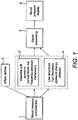
Figure 1 is a diagram showing a generic system layout for the system of the present invention; -
Figure 2 (A and B): Examples of blood pressure measurement system set ups (left), and example of cuff pressure waveforms (top right of each window) and high frequency cuff pressure changes (right bottom of each window) recorded from the blood pressure cuff; -
Figure 3 : Three possible embodiments of high frequency (HF) pressure sensor location. -
Figure 4 : High frequency cuff pressure changes recorded with the sensor at two locations. -
Figure 5 : Processed high frequency cuff pressure changes. Top: Filtered high frequency cuff pressure changes using 30-300Hz band pass filter; Middle: with further processing of noise reduction (which may be required if noise is present; Bottom: with further process of enhancement.
Note: This example clearly shows that more accurate BP determination could be achieved after further processing, from which the noises above SBP and below DBP are reduced.
Enhancement: The filtered signal is processed by the multiplication of a transfer function. This process reduces the signals with low amplitude, and enhances the signals with relatively large amplitude.
Noise reduction: At beat-by-beat level, one segment of high frequency cuff pressure change, defined from a fixed timing window referenced to its corresponding foot of the low frequency oscillometric pulse, is further processed for noise reduction using a low pass filter to better identify micro-pulses. The original segment is then replaced by the filtered segment. -
Figure 6 : Low frequency oscillometic pulses (top), and cuff pressure changes (middle) that include components of both the high frequency micro-signal pulses and the oscillometric waveform, enabling the position of the arterial opening pulses relative to the oscillometric pulses to be more easily seen. On the bottom part of the figure, the time difference between the foot of the oscillometic pulses (marked with Δ) and the peaks of the cuff pressure changes signal (marked with *) are shown. Initially these times simply detect the leading edge of the oscillometric pulses, but as soon as SBP is reached the timing suddenly changes to the peak of the oscillometric pulse, and then continues to shorten until DBP is reached. Analysis of the high frequency snap micro-signal pulse relative to the oscillometric pulse enables a detection time window to be set, helping to exclude noise and making the detection of SBP and DBP more accurate in noisy conditions. - A general system according to the present invention is shown in
Figure 1 . The blood pressure cuff orchamber 1 may be a conventional cuff or may be of a custom design including that of a chamber without inner layer (the chamber typically having a lower internal volume c.f. a conventional cuff). - In a preferred embodiment the cuff or chamber incorporates a microphone, however this could instead be in close proximity to the cuff or chamber or in fact remote from the cuff or chamber, for example in a main device body which houses the processor. A low frequency pressure transducer is also present to read baseline cuff pressure. In certain embodiments a single pressure sensor or pressure transducer reads both low frequencies and high frequencies.
- The system may include a means of inflating/deflating the
cuff 2 or a means of pressurising/depressurising the chamber if that is being used. Cuff inflation/deflation of chamber pressurisation/depressurisation may be either manual or automated as is known from conventional sphygmomanometer technology. Alternativelysuch means 2 may not form part of the system but the system may be attachable to said means. - The system reads both
baseline cuff pressure 3 and low amplitude high frequency pressure changes 4. - The system may comprise
additional signal processing 5 utilising hardware and/or software (which optionally may be included in the device body). This may include one or more of; a microphone amplifier, an analogue filter, a digital filter, digital discrimination, noise reduction means, micro pulse enhancement means, and pulse detection algorithms. Signal processing and enhancement can provide more accurate BP determination as "noises" above SBP and below DBP are reduced. - Finally, the recorded, and potentially further processed readings are displayed 6 to a user. Typically this will be via a visual display integrated with the processer, for example in a device body. The information could however be sent, using known data transfer technology, to a remote device such as a computer, laptop, mobile device for display or manipulation. As well as BP readings the following information could be obtained or determined and displayed; real-time cuff pressure (as for conventional device), stored 'micro pulse' waveform, SBP and DPB, heart rate and heart rhythm.
- Determination of SBP and DBP can be carried out by;
manually positioning cursors on the displayed waveform trace of the micro pulse; automatic detection of SBP and DBP based on: - the appearance and disappearance of processed micro-pulses, or
- time difference between initial hydraulic pulse (or oscillometric pulse foot) and micro- pulse
- Using the system of the present invention, auscultation with a stethoscope is no longer required as accurate BP readings can be obtained based on the micro-pulses detected. Examples of the blood pressure measurement system set up alongside recorded waveforms are shown in
Figure 2. Figure 2A shows a system where a cuff has a single pressure transducer or pressure sensor integrated into the wall of the cuff that is able to sense and record both low frequency (at least 0-2Hz) and high frequency (at least greater than >20Hz) pressure variances.Figure 2B shows a system where a cuff has a first high pressure transducer or pressure sensor integrated into the wall of the cuff that is able to sense and record high frequency (at least greater than >20Hz) pressure variances and a low frequency pressure transducer or pressure sensor that is able to sense and record low frequency (at least 0-2 Hz) remote from the cuff but in pneumatic communication therewith (for example in tubing associated with both the cuff and a means for inflating the same). In both 2A and 2B example cuff pressure waveforms are shown in the top right and example high frequency cuff pressure changes (micro-pulses) are shown in the bottom right. - The system directly senses the pressure variances in the air or fluid in the cuff or chamber (or "listens" to the sounds caused by changes in air or fluid pressure in the cuff). As the cuff now both acts as the site of restricted/released blood flow and the site of sensing pressure variances it is hypothesised that this allows the opening and closing of the artery to be more clearly sensed, in turn allowing systolic and diastolic blood pressure to be determined using the small micropulses that have been identified by the inventors using their direct readings. The system can therefore directly detect those pressure changes resulting from the artery opening and closing below the cuff, termed micropulses herein, and is not reliant on the arterial pulse producing an oscillometric pressure waveform (from which the blood pressures can only be estimated).
- In use, a cuff (which could be replaced with an appropriate chamber) is placed around an individual's arm at approximately heart height. In one embodiment, the cuff comprises a pressure sensor in the form of a sensor located on the wall of the cuff.
Figure 3 shows three further possible variants where a high frequency transducer or pressure sensor is located at different positions, however it would be understood by one skilled in the art that a single pressure sensor able to sense high and low frequencies could equally by placed in such positions. - In a preferred embodiment the sensor is embedded into the wall of the cuff and heat sealed in place. The cuff is inflated to a pressure in excess of systolic pressure; this may be manually or under the control of a processor. Optionally, pulse wave amplitude value, heart rate, systolic blood pressure and various other parameters can be sensed and recorded during inflation of the cuff if so desired using standard methodologies such as the oscillometric method. It has been found that this particular embodiment where the high frequency pressure sensor (or combined high and low frequency pressure sensor) is integrated into the cuff (or chamber) provides a particularly clear signal.
Figure 4 shows high frequency cuff pressure changes recorded with the sensor at two locations. When the sensor is remote from the cuff a resonant effect is observed whereas when the high frequency pressure sensor is in the cuff the resonant effect is not observed. - In certain embodiments, the reading(s) from the pressure sensor or sensors are further processed to give more accurate readings.
Figure 5 shows how processing the variations in high frequency cuff pressure can provide very accurate BP determination. For example, the top graph shows filtered high frequency cuff pressure changes using 30-300Hz band pass filter. The middle graph shows the effect of further process of enhancement - The filtered signal is processed by the multiplication of a transfer function. This process reduces the signals with low amplitude, and enhances the signals with relatively large amplitude. The bottom graph show further processing with noise reduction - at beat-by-beat level, one segment of high frequency cuff pressure change, which is defined from a fixed timing window referenced to its corresponding foot of the low frequency oscillometric pulse, is further processed for noise reduction. The original segment is then replaced by the filtered segment. These graphs clearly show that more accurate BP determination can be achieved after further processing, from which the noises above SBP and below DBP are reduced. -
Figure 6 shows how the signals can be used to determine BPs accurately using low frequency oscillometic pulses (top) and cuff pressure changes (middle) recorded from the cuff that include components of both the high frequency snap micro-signal pulses and the oscillometric waveform, enabling the position of the arterial opening pulses relative to the oscillometric pulses to be more easily seen. - In summary the present invention allows for accurate determination of true blood pressures. It will be understood that a preferred embodiment has at least the high frequency sensor, transducer incorporated into the wall of the cuff or chamber that is in contact with a person's arm in use - this provides particularly accurate readings. Further, the processing of the signal allows for very accurate results to be obtained with minimal requirements for user training.
Claims (19)
- A blood pressure measurement system comprising;a cuff or a chamber which is attachable to apparatus selectively able to pressurise said cuff or chamber;at least one pressure sensor in fluid communication with the cuff or chamber, said sensor able to sense cuff or chamber pressure and variances therein at least above 20Hz;at least one pressure sensor in fluid communication with the cuff or chamber, said sensor able to sense cuff or chamber pressure and variances therein at least equal to or below 2Hz; andmeans to analyse the sensed pressure and variances, wherein said means is configured to:- analyse the pressure and variances therein at least above 20Hz to identify micro-pulses, wherein the micro-pulses comprise very low amplitude fast negative pressure deflections superimposed on a rising pressure component of an oscillometric waveform, and wherein the micro-pulses are associated with opening and closing of an artery and only exist between systolic blood pressure and diastolic blood pressure;- analyse the pressure and variances therein at least equal to or below 2Hz to determine a baseline cuff or chamber pressure; and- determine systolic blood pressure and diastolic blood pressure from the baseline cuff or chamber pressure in conjunction with the micro-pulses.
- A blood pressure measurement system as claimed in claim 1 wherein there is a single pressure sensor that is able to sense cuff or chamber pressure and variances therein above 20Hz and sense cuff or chamber pressure and variances therein below 2Hz; and/or wherein said pressure sensor is able to sense cuff or chamber pressure, and variances therein at least up to 100Hz.
- A blood pressure measurement system as in claim 1 or claim 2 wherein said pressure sensor is able to sense cuff or chamber pressure, and variances therein at least up to 300Hz.
- A blood pressure measurement system as in any of the previous claims wherein the reading from the pressure sensor is filtered electronically to remove components below 20 Hz or 30 Hz.
- A blood pressure measurement system as in any of the previous claims wherein the pressure sensor is part of the cuff or chamber; and optionally wherein the pressure sensor is integrated into a wall of the cuff or chamber; or in close proximity to, or is proximal to, the cuff or chamber.
- A blood pressure measurement system as in claim 1 wherein, the system comprises a first high frequency pressure sensor and a second low frequency pressure sensor.
- A blood pressure measurement system as in claim 6 wherein the high frequency pressure sensor is configured to sense at least above 20 Hz, or above, approximately 30Hz.
- A blood pressure measurement system as in claim 6 wherein the high frequency pressure sensor is configured to sense from approximately 20Hz or approximately 30Hz, to approximately 300Hz.
- A blood pressure measurement system as in any of claims 6-8 wherein, the second low frequency pressure sensor is able to sense cuff or chamber pressure and variances therein at least below 2Hz; and optionally wherein the reading from the high frequency pressure sensor is filtered electronically to remove components below 20 Hz.
- A blood pressure measurement system as in any one of the preceding claims comprising a classic band-pass analogue/digital filter between 20 and 300Hz, wherein the filtered signal is enhanced by the multiplication of a transfer function, reducing signals with low amplitude and enhancing the signals with large amplitude.
- A blood pressure measurement system as in any of claims 6-10 wherein the reading from the high frequency pressure sensor is filtered electronically to remove components below 30 Hz.
- A blood pressure measurement system as in any of claims 6 to 11 wherein the low frequency pressure sensor and/or the high pressure sensor is part of the cuff or chamber, or is close proximity to, or is proximal to, the cuff or chamber.
- A blood pressure measurement system as in any of the previous claims wherein the system comprises a means for processing the information sensed by the at least one pressure sensor, and/or means for storing the information from the at least one pressure sensor, and/or means for displaying the information to a user.
- A blood pressure measurement system as in any of the previous claims wherein a segment of high frequency cuff pressure change, which is defined from a fixed timing window referenced to its corresponding foot of a low frequency oscillometric pulse, is further processed using a low pass filter and the original segment is then replaced by a filtered segment.
- A blood pressure measurement system as in any of claims 1 to 13 wherein blood pressure readings are determined using the time difference information.
- A method for measuring blood pressure using a cuff or chamber, the method comprising:- sensing high frequency signals of greater than at least 20Hz associated with a cuff or chamber pressure;- sensing low frequency signals of equal to or less than at least 2 Hz associated with a baseline cuff or chamber pressure; and- by means comprising a processor:- analysing the high frequency signals to identify micro-pulses, wherein the micro-pulses comprise very low amplitude fast negative pressure deflections superimposed on a rising pressure component of an oscillometric waveform, and wherein the micro-pulses are associated with opening and closing of an artery and only exist between systolic blood pressure and diastolic blood pressure;- analysing the low frequency signals to determine the baseline cuff or chamber pressure; and- determining systolic blood pressure and diastolic blood pressure from the baseline cuff or chamber pressure in conjunction with the micro-pulses.
- A method as claimed in claim 16 further comprising;incrementally increasing a pressure of the cuff or chamber from below diastolic pressure; and wherein diastolic blood pressure is determined as the cuff or chamber pressure at which the high frequency micro-pulses are first detected, and systolic blood pressure is determined as being the cuff or chamber pressure at which the high frequency micro-pulses cease to be detected; orincrementally or smoothly decreasing a pressure of a cuff or chamber from above systolic pressure; and wherein systolic blood pressure is determined as the cuff or chamber pressure at which the high frequency micro-pulses are first detected, and diastolic blood pressure is determined as being the cuff or chamber pressure at which the high frequency micro-pulses cease to be detected.
- The method of any one of claims 16 to 17 further comprising the step of sensing all high frequency signals of greater than at least 20 Hz between systolic and diastolic blood pressure.
- Use of the system of any of claims 1 to 15 to measure blood pressure by sensing high frequency signals associated with systolic blood pressure and diastolic blood pressure.
Applications Claiming Priority (2)
| Application Number | Priority Date | Filing Date | Title |
|---|---|---|---|
| GBGB1506420.7A GB201506420D0 (en) | 2015-04-15 | 2015-04-15 | Improved blood pressure sensor |
| PCT/GB2016/051065 WO2016166554A1 (en) | 2015-04-15 | 2016-04-15 | An improved blood pressure measurement system |
Publications (2)
| Publication Number | Publication Date |
|---|---|
| EP3282934A1 EP3282934A1 (en) | 2018-02-21 |
| EP3282934B1 true EP3282934B1 (en) | 2020-09-09 |
Family
ID=53333848
Family Applications (1)
| Application Number | Title | Priority Date | Filing Date |
|---|---|---|---|
| EP16722342.9A Active EP3282934B1 (en) | 2015-04-15 | 2016-04-15 | An improved blood pressure measurement system |
Country Status (8)
| Country | Link |
|---|---|
| US (1) | US20180103856A1 (en) |
| EP (1) | EP3282934B1 (en) |
| JP (1) | JP6854804B2 (en) |
| KR (1) | KR102570356B1 (en) |
| BR (1) | BR112017021302B1 (en) |
| GB (1) | GB201506420D0 (en) |
| MY (1) | MY197385A (en) |
| WO (1) | WO2016166554A1 (en) |
Families Citing this family (2)
| Publication number | Priority date | Publication date | Assignee | Title |
|---|---|---|---|---|
| US10874307B2 (en) * | 2017-01-24 | 2020-12-29 | Verily Life Sciences Llc | Digital artery blood pressure monitor |
| KR20200065612A (en) * | 2018-11-30 | 2020-06-09 | 전자부품연구원 | ECG Monitoring Device and Method with FSR Sensor |
Family Cites Families (16)
| Publication number | Priority date | Publication date | Assignee | Title |
|---|---|---|---|---|
| JPS5470678A (en) * | 1977-11-15 | 1979-06-06 | Matsushita Electric Works Ltd | Automatic digital hemadynamometer |
| US4592366A (en) * | 1984-04-16 | 1986-06-03 | Matsushita Electric Works, Ltd. | Automated blood pressure monitoring instrument |
| JPH0687841B2 (en) * | 1986-09-18 | 1994-11-09 | コーリン電子株式会社 | Blood pressure measurement device |
| JPS63171539A (en) * | 1987-01-10 | 1988-07-15 | コーリン電子株式会社 | Automatic blood pressure measuring apparatus |
| US4890625A (en) * | 1988-03-24 | 1990-01-02 | Spacelabs, Inc. | Blood pressure cuff with integral acoustic pickup cup |
| EP0483355B1 (en) * | 1990-05-17 | 1996-08-28 | Mitsuei Tomita | Device for detecting and displaying information on blood circulation |
| JPH08322811A (en) * | 1995-05-30 | 1996-12-10 | Nippon Colin Co Ltd | Automatic sphygmomanometer |
| US7736314B2 (en) * | 2004-08-31 | 2010-06-15 | University Of Washington | Ultrasonic technique for assessing wall vibrations in stenosed blood vessels |
| US7403806B2 (en) * | 2005-06-28 | 2008-07-22 | General Electric Company | System for prefiltering a plethysmographic signal |
| US7153269B1 (en) * | 2006-01-05 | 2006-12-26 | The General Electric Company | Method and system for estimation of blood pressure during cuff inflation |
| US20070203416A1 (en) * | 2006-02-28 | 2007-08-30 | Andrew Lowe | Blood pressure cuffs |
| DE102008008840A1 (en) * | 2008-02-13 | 2009-09-24 | Up Management Gmbh | Method and device for the non-invasive measurement of dynamic heart-lung interaction parameters |
| KR20100094059A (en) * | 2009-02-18 | 2010-08-26 | 전북대학교산학협력단 | Apparatus and method for automatic measurement and wireless transmission of blood pressure values based on oscillometric method and k-sound method |
| JP2011200610A (en) * | 2010-03-26 | 2011-10-13 | Terumo Corp | Electronic sphygmomanometer |
| JP5600023B2 (en) * | 2010-03-26 | 2014-10-01 | テルモ株式会社 | Electronic blood pressure monitor |
| CN104000573B (en) * | 2014-05-29 | 2016-01-13 | 东北大学 | Based on central aortic pulse wave monitoring system and the method for body surface 2 pulse waves |
-
2015
- 2015-04-15 GB GBGB1506420.7A patent/GB201506420D0/en not_active Ceased
-
2016
- 2016-04-15 BR BR112017021302-8A patent/BR112017021302B1/en active IP Right Grant
- 2016-04-15 US US15/565,896 patent/US20180103856A1/en active Pending
- 2016-04-15 KR KR1020177032695A patent/KR102570356B1/en active IP Right Grant
- 2016-04-15 EP EP16722342.9A patent/EP3282934B1/en active Active
- 2016-04-15 WO PCT/GB2016/051065 patent/WO2016166554A1/en active Application Filing
- 2016-04-15 JP JP2018505543A patent/JP6854804B2/en active Active
- 2016-04-15 MY MYPI2017703765A patent/MY197385A/en unknown
Non-Patent Citations (1)
| Title |
|---|
| None * |
Also Published As
| Publication number | Publication date |
|---|---|
| KR102570356B1 (en) | 2023-08-23 |
| BR112017021302A2 (en) | 2018-06-26 |
| GB201506420D0 (en) | 2015-05-27 |
| BR112017021302A8 (en) | 2018-07-31 |
| US20180103856A1 (en) | 2018-04-19 |
| JP6854804B2 (en) | 2021-04-07 |
| WO2016166554A1 (en) | 2016-10-20 |
| KR20170140269A (en) | 2017-12-20 |
| MY197385A (en) | 2023-06-15 |
| JP2018515302A (en) | 2018-06-14 |
| EP3282934A1 (en) | 2018-02-21 |
| BR112017021302B1 (en) | 2022-11-16 |
Similar Documents
| Publication | Publication Date | Title |
|---|---|---|
| EP2601885B1 (en) | Non-invasive blood pressure measuring apparatus and measuring method thereof | |
| JP4409878B2 (en) | Method and apparatus for determining blood pressure using a pressure pulse duty cycle | |
| US5094244A (en) | Apparatus and process for determining systolic blood pressure, diastolic blood pressure, mean arterial blood pressure, pulse rate, pulse wave shape, respiratory pattern, and respiratory rate | |
| US6440080B1 (en) | Automatic oscillometric apparatus and method for measuring blood pressure | |
| EP3318183B1 (en) | Auxiliary device for blood pressure measurement and blood pressure measuring equipment | |
| JP2009101089A (en) | Blood pressure measuring apparatus and its control method | |
| US6517495B1 (en) | Automatic indirect non-invasive apparatus and method for determining diastolic blood pressure by calibrating an oscillation waveform | |
| KR100804454B1 (en) | Superior-and-inferior-limb blood-pressure index measuring apparatus | |
| CN110840429A (en) | Korotkoff sound-based blood pressure measurement method and blood pressure measurement and cardiovascular system evaluation system | |
| KR101604078B1 (en) | Blood pressure monitoring apparatus and method of low pressurization | |
| US10881307B1 (en) | Devices and systems for correcting errors in blood pressure measurements | |
| US20120029366A1 (en) | Blood pressure detection apparatus and blood pressure detection method | |
| EP3282934B1 (en) | An improved blood pressure measurement system | |
| KR101774043B1 (en) | Auto sphygmomanometry apparatus | |
| EP2369984B1 (en) | Method of measuring blood pressure and apparatus for performing the same | |
| JP2010194108A (en) | Blood pressure information measuring device and calculation program for arteriosclerosis degree index | |
| JP2013530769A (en) | Sphygmomanometer cuff | |
| JP2018515302A5 (en) | ||
| JP2001309894A (en) | Equipment for measuring peripheral venous pressure and its method | |
| JP4879038B2 (en) | Blood pressure measurement device capable of pulse wave detection | |
| CN211883777U (en) | Korotkoff sound-based blood pressure measurement and cardiovascular system evaluation system | |
| JP5006509B2 (en) | Pulse wave velocity measurement method for measuring pulse wave velocity in a pulse wave velocity measuring device | |
| KR20180033018A (en) | Wrist watch typed blood pressure measuring device using korotkoff sound | |
| KR20240139539A (en) | Apparatus and method for measuring blood pressure | |
| Geršak et al. | Virtual auscultatory non-invasive blood pressure monitor |
Legal Events
| Date | Code | Title | Description |
|---|---|---|---|
| STAA | Information on the status of an ep patent application or granted ep patent |
Free format text: STATUS: THE INTERNATIONAL PUBLICATION HAS BEEN MADE |
|
| PUAI | Public reference made under article 153(3) epc to a published international application that has entered the european phase |
Free format text: ORIGINAL CODE: 0009012 |
|
| STAA | Information on the status of an ep patent application or granted ep patent |
Free format text: STATUS: REQUEST FOR EXAMINATION WAS MADE |
|
| 17P | Request for examination filed |
Effective date: 20171010 |
|
| AK | Designated contracting states |
Kind code of ref document: A1 Designated state(s): AL AT BE BG CH CY CZ DE DK EE ES FI FR GB GR HR HU IE IS IT LI LT LU LV MC MK MT NL NO PL PT RO RS SE SI SK SM TR |
|
| AX | Request for extension of the european patent |
Extension state: BA ME |
|
| RAP1 | Party data changed (applicant data changed or rights of an application transferred) |
Owner name: UNIVERSITY OF NEWCASTLE UPON TYNE Owner name: A C COSSOR & SON (TECHNOLOGY) LTD |
|
| DAV | Request for validation of the european patent (deleted) | ||
| DAX | Request for extension of the european patent (deleted) | ||
| STAA | Information on the status of an ep patent application or granted ep patent |
Free format text: STATUS: EXAMINATION IS IN PROGRESS |
|
| 17Q | First examination report despatched |
Effective date: 20190225 |
|
| GRAP | Despatch of communication of intention to grant a patent |
Free format text: ORIGINAL CODE: EPIDOSNIGR1 |
|
| STAA | Information on the status of an ep patent application or granted ep patent |
Free format text: STATUS: GRANT OF PATENT IS INTENDED |
|
| GRAS | Grant fee paid |
Free format text: ORIGINAL CODE: EPIDOSNIGR3 |
|
| INTG | Intention to grant announced |
Effective date: 20200706 |
|
| GRAA | (expected) grant |
Free format text: ORIGINAL CODE: 0009210 |
|
| STAA | Information on the status of an ep patent application or granted ep patent |
Free format text: STATUS: THE PATENT HAS BEEN GRANTED |
|
| AK | Designated contracting states |
Kind code of ref document: B1 Designated state(s): AL AT BE BG CH CY CZ DE DK EE ES FI FR GB GR HR HU IE IS IT LI LT LU LV MC MK MT NL NO PL PT RO RS SE SI SK SM TR |
|
| REG | Reference to a national code |
Ref country code: GB Ref legal event code: FG4D |
|
| REG | Reference to a national code |
Ref country code: DE Ref legal event code: R081 Ref document number: 602016043664 Country of ref document: DE Owner name: UNIVERSITY OF NEWCASTLE UPON TYNE, NEWCASTLE U, GB Free format text: FORMER OWNERS: A C COSSOR & SON (TECHNOLOGY) LTD, HARLOW, GB; UNIVERSITY OF NEWCASTLE UPON TYNE, NEWCASTLE UPON TYNE, GB Ref country code: DE Ref legal event code: R081 Ref document number: 602016043664 Country of ref document: DE Owner name: A C COSSOR & SON (TECHNOLOGY) LTD, GB Free format text: FORMER OWNERS: A C COSSOR & SON (TECHNOLOGY) LTD, HARLOW, GB; UNIVERSITY OF NEWCASTLE UPON TYNE, NEWCASTLE UPON TYNE, GB Ref country code: AT Ref legal event code: REF Ref document number: 1310525 Country of ref document: AT Kind code of ref document: T Effective date: 20200915 Ref country code: CH Ref legal event code: EP |
|
| REG | Reference to a national code |
Ref country code: IE Ref legal event code: FG4D |
|
| REG | Reference to a national code |
Ref country code: DE Ref legal event code: R096 Ref document number: 602016043664 Country of ref document: DE |
|
| REG | Reference to a national code |
Ref country code: LT Ref legal event code: MG4D |
|
| PG25 | Lapsed in a contracting state [announced via postgrant information from national office to epo] |
Ref country code: BG Free format text: LAPSE BECAUSE OF FAILURE TO SUBMIT A TRANSLATION OF THE DESCRIPTION OR TO PAY THE FEE WITHIN THE PRESCRIBED TIME-LIMIT Effective date: 20201209 Ref country code: SE Free format text: LAPSE BECAUSE OF FAILURE TO SUBMIT A TRANSLATION OF THE DESCRIPTION OR TO PAY THE FEE WITHIN THE PRESCRIBED TIME-LIMIT Effective date: 20200909 Ref country code: HR Free format text: LAPSE BECAUSE OF FAILURE TO SUBMIT A TRANSLATION OF THE DESCRIPTION OR TO PAY THE FEE WITHIN THE PRESCRIBED TIME-LIMIT Effective date: 20200909 Ref country code: NO Free format text: LAPSE BECAUSE OF FAILURE TO SUBMIT A TRANSLATION OF THE DESCRIPTION OR TO PAY THE FEE WITHIN THE PRESCRIBED TIME-LIMIT Effective date: 20201209 Ref country code: FI Free format text: LAPSE BECAUSE OF FAILURE TO SUBMIT A TRANSLATION OF THE DESCRIPTION OR TO PAY THE FEE WITHIN THE PRESCRIBED TIME-LIMIT Effective date: 20200909 Ref country code: LT Free format text: LAPSE BECAUSE OF FAILURE TO SUBMIT A TRANSLATION OF THE DESCRIPTION OR TO PAY THE FEE WITHIN THE PRESCRIBED TIME-LIMIT Effective date: 20200909 Ref country code: GR Free format text: LAPSE BECAUSE OF FAILURE TO SUBMIT A TRANSLATION OF THE DESCRIPTION OR TO PAY THE FEE WITHIN THE PRESCRIBED TIME-LIMIT Effective date: 20201210 |
|
| REG | Reference to a national code |
Ref country code: AT Ref legal event code: MK05 Ref document number: 1310525 Country of ref document: AT Kind code of ref document: T Effective date: 20200909 |
|
| REG | Reference to a national code |
Ref country code: NL Ref legal event code: MP Effective date: 20200909 |
|
| PG25 | Lapsed in a contracting state [announced via postgrant information from national office to epo] |
Ref country code: LV Free format text: LAPSE BECAUSE OF FAILURE TO SUBMIT A TRANSLATION OF THE DESCRIPTION OR TO PAY THE FEE WITHIN THE PRESCRIBED TIME-LIMIT Effective date: 20200909 Ref country code: PL Free format text: LAPSE BECAUSE OF FAILURE TO SUBMIT A TRANSLATION OF THE DESCRIPTION OR TO PAY THE FEE WITHIN THE PRESCRIBED TIME-LIMIT Effective date: 20200909 Ref country code: RS Free format text: LAPSE BECAUSE OF FAILURE TO SUBMIT A TRANSLATION OF THE DESCRIPTION OR TO PAY THE FEE WITHIN THE PRESCRIBED TIME-LIMIT Effective date: 20200909 |
|
| PG25 | Lapsed in a contracting state [announced via postgrant information from national office to epo] |
Ref country code: RO Free format text: LAPSE BECAUSE OF FAILURE TO SUBMIT A TRANSLATION OF THE DESCRIPTION OR TO PAY THE FEE WITHIN THE PRESCRIBED TIME-LIMIT Effective date: 20200909 Ref country code: PT Free format text: LAPSE BECAUSE OF FAILURE TO SUBMIT A TRANSLATION OF THE DESCRIPTION OR TO PAY THE FEE WITHIN THE PRESCRIBED TIME-LIMIT Effective date: 20210111 Ref country code: SM Free format text: LAPSE BECAUSE OF FAILURE TO SUBMIT A TRANSLATION OF THE DESCRIPTION OR TO PAY THE FEE WITHIN THE PRESCRIBED TIME-LIMIT Effective date: 20200909 Ref country code: CZ Free format text: LAPSE BECAUSE OF FAILURE TO SUBMIT A TRANSLATION OF THE DESCRIPTION OR TO PAY THE FEE WITHIN THE PRESCRIBED TIME-LIMIT Effective date: 20200909 Ref country code: EE Free format text: LAPSE BECAUSE OF FAILURE TO SUBMIT A TRANSLATION OF THE DESCRIPTION OR TO PAY THE FEE WITHIN THE PRESCRIBED TIME-LIMIT Effective date: 20200909 |
|
| PG25 | Lapsed in a contracting state [announced via postgrant information from national office to epo] |
Ref country code: ES Free format text: LAPSE BECAUSE OF FAILURE TO SUBMIT A TRANSLATION OF THE DESCRIPTION OR TO PAY THE FEE WITHIN THE PRESCRIBED TIME-LIMIT Effective date: 20200909 Ref country code: AL Free format text: LAPSE BECAUSE OF FAILURE TO SUBMIT A TRANSLATION OF THE DESCRIPTION OR TO PAY THE FEE WITHIN THE PRESCRIBED TIME-LIMIT Effective date: 20200909 Ref country code: AT Free format text: LAPSE BECAUSE OF FAILURE TO SUBMIT A TRANSLATION OF THE DESCRIPTION OR TO PAY THE FEE WITHIN THE PRESCRIBED TIME-LIMIT Effective date: 20200909 Ref country code: IS Free format text: LAPSE BECAUSE OF FAILURE TO SUBMIT A TRANSLATION OF THE DESCRIPTION OR TO PAY THE FEE WITHIN THE PRESCRIBED TIME-LIMIT Effective date: 20210109 |
|
| REG | Reference to a national code |
Ref country code: DE Ref legal event code: R097 Ref document number: 602016043664 Country of ref document: DE |
|
| PG25 | Lapsed in a contracting state [announced via postgrant information from national office to epo] |
Ref country code: SK Free format text: LAPSE BECAUSE OF FAILURE TO SUBMIT A TRANSLATION OF THE DESCRIPTION OR TO PAY THE FEE WITHIN THE PRESCRIBED TIME-LIMIT Effective date: 20200909 |
|
| PLBE | No opposition filed within time limit |
Free format text: ORIGINAL CODE: 0009261 |
|
| STAA | Information on the status of an ep patent application or granted ep patent |
Free format text: STATUS: NO OPPOSITION FILED WITHIN TIME LIMIT |
|
| 26N | No opposition filed |
Effective date: 20210610 |
|
| PG25 | Lapsed in a contracting state [announced via postgrant information from national office to epo] |
Ref country code: SI Free format text: LAPSE BECAUSE OF FAILURE TO SUBMIT A TRANSLATION OF THE DESCRIPTION OR TO PAY THE FEE WITHIN THE PRESCRIBED TIME-LIMIT Effective date: 20200909 Ref country code: DK Free format text: LAPSE BECAUSE OF FAILURE TO SUBMIT A TRANSLATION OF THE DESCRIPTION OR TO PAY THE FEE WITHIN THE PRESCRIBED TIME-LIMIT Effective date: 20200909 |
|
| PG25 | Lapsed in a contracting state [announced via postgrant information from national office to epo] |
Ref country code: IT Free format text: LAPSE BECAUSE OF FAILURE TO SUBMIT A TRANSLATION OF THE DESCRIPTION OR TO PAY THE FEE WITHIN THE PRESCRIBED TIME-LIMIT Effective date: 20200909 |
|
| PG25 | Lapsed in a contracting state [announced via postgrant information from national office to epo] |
Ref country code: MC Free format text: LAPSE BECAUSE OF FAILURE TO SUBMIT A TRANSLATION OF THE DESCRIPTION OR TO PAY THE FEE WITHIN THE PRESCRIBED TIME-LIMIT Effective date: 20200909 |
|
| PG25 | Lapsed in a contracting state [announced via postgrant information from national office to epo] |
Ref country code: LU Free format text: LAPSE BECAUSE OF NON-PAYMENT OF DUE FEES Effective date: 20210415 |
|
| REG | Reference to a national code |
Ref country code: BE Ref legal event code: MM Effective date: 20210430 |
|
| PG25 | Lapsed in a contracting state [announced via postgrant information from national office to epo] |
Ref country code: LI Free format text: LAPSE BECAUSE OF NON-PAYMENT OF DUE FEES Effective date: 20210430 Ref country code: CH Free format text: LAPSE BECAUSE OF NON-PAYMENT OF DUE FEES Effective date: 20210430 |
|
| PG25 | Lapsed in a contracting state [announced via postgrant information from national office to epo] |
Ref country code: IE Free format text: LAPSE BECAUSE OF NON-PAYMENT OF DUE FEES Effective date: 20210415 |
|
| PG25 | Lapsed in a contracting state [announced via postgrant information from national office to epo] |
Ref country code: IS Free format text: LAPSE BECAUSE OF FAILURE TO SUBMIT A TRANSLATION OF THE DESCRIPTION OR TO PAY THE FEE WITHIN THE PRESCRIBED TIME-LIMIT Effective date: 20210109 |
|
| PG25 | Lapsed in a contracting state [announced via postgrant information from national office to epo] |
Ref country code: BE Free format text: LAPSE BECAUSE OF NON-PAYMENT OF DUE FEES Effective date: 20210430 |
|
| PG25 | Lapsed in a contracting state [announced via postgrant information from national office to epo] |
Ref country code: HU Free format text: LAPSE BECAUSE OF FAILURE TO SUBMIT A TRANSLATION OF THE DESCRIPTION OR TO PAY THE FEE WITHIN THE PRESCRIBED TIME-LIMIT; INVALID AB INITIO Effective date: 20160415 |
|
| P01 | Opt-out of the competence of the unified patent court (upc) registered |
Effective date: 20230516 |
|
| PG25 | Lapsed in a contracting state [announced via postgrant information from national office to epo] |
Ref country code: NL Free format text: LAPSE BECAUSE OF NON-PAYMENT OF DUE FEES Effective date: 20200923 Ref country code: CY Free format text: LAPSE BECAUSE OF FAILURE TO SUBMIT A TRANSLATION OF THE DESCRIPTION OR TO PAY THE FEE WITHIN THE PRESCRIBED TIME-LIMIT Effective date: 20200909 |
|
| PG25 | Lapsed in a contracting state [announced via postgrant information from national office to epo] |
Ref country code: MK Free format text: LAPSE BECAUSE OF FAILURE TO SUBMIT A TRANSLATION OF THE DESCRIPTION OR TO PAY THE FEE WITHIN THE PRESCRIBED TIME-LIMIT Effective date: 20200909 |
|
| PGFP | Annual fee paid to national office [announced via postgrant information from national office to epo] |
Ref country code: GB Payment date: 20240411 Year of fee payment: 9 |
|
| PGFP | Annual fee paid to national office [announced via postgrant information from national office to epo] |
Ref country code: DE Payment date: 20240418 Year of fee payment: 9 |
|
| PGFP | Annual fee paid to national office [announced via postgrant information from national office to epo] |
Ref country code: FR Payment date: 20240423 Year of fee payment: 9 |