EP3316791B1 - Multi-mode capacitive micromachined ultrasound transducer and associated devices and systems - Google Patents
Multi-mode capacitive micromachined ultrasound transducer and associated devices and systems Download PDFInfo
- Publication number
- EP3316791B1 EP3316791B1 EP16731985.4A EP16731985A EP3316791B1 EP 3316791 B1 EP3316791 B1 EP 3316791B1 EP 16731985 A EP16731985 A EP 16731985A EP 3316791 B1 EP3316791 B1 EP 3316791B1
- Authority
- EP
- European Patent Office
- Prior art keywords
- sensor
- intravascular
- sensor assembly
- data
- imaging
- Prior art date
- Legal status (The legal status is an assumption and is not a legal conclusion. Google has not performed a legal analysis and makes no representation as to the accuracy of the status listed.)
- Active
Links
Images

Classifications
-
- A—HUMAN NECESSITIES
- A61—MEDICAL OR VETERINARY SCIENCE; HYGIENE
- A61B—DIAGNOSIS; SURGERY; IDENTIFICATION
- A61B8/00—Diagnosis using ultrasonic, sonic or infrasonic waves
- A61B8/12—Diagnosis using ultrasonic, sonic or infrasonic waves in body cavities or body tracts, e.g. by using catheters
-
- A—HUMAN NECESSITIES
- A61—MEDICAL OR VETERINARY SCIENCE; HYGIENE
- A61B—DIAGNOSIS; SURGERY; IDENTIFICATION
- A61B8/00—Diagnosis using ultrasonic, sonic or infrasonic waves
- A61B8/04—Measuring blood pressure
-
- A—HUMAN NECESSITIES
- A61—MEDICAL OR VETERINARY SCIENCE; HYGIENE
- A61B—DIAGNOSIS; SURGERY; IDENTIFICATION
- A61B8/00—Diagnosis using ultrasonic, sonic or infrasonic waves
- A61B8/44—Constructional features of the ultrasonic, sonic or infrasonic diagnostic device
- A61B8/4444—Constructional features of the ultrasonic, sonic or infrasonic diagnostic device related to the probe
- A61B8/445—Details of catheter construction
-
- A—HUMAN NECESSITIES
- A61—MEDICAL OR VETERINARY SCIENCE; HYGIENE
- A61B—DIAGNOSIS; SURGERY; IDENTIFICATION
- A61B8/00—Diagnosis using ultrasonic, sonic or infrasonic waves
- A61B8/44—Constructional features of the ultrasonic, sonic or infrasonic diagnostic device
- A61B8/4483—Constructional features of the ultrasonic, sonic or infrasonic diagnostic device characterised by features of the ultrasound transducer
-
- B—PERFORMING OPERATIONS; TRANSPORTING
- B06—GENERATING OR TRANSMITTING MECHANICAL VIBRATIONS IN GENERAL
- B06B—METHODS OR APPARATUS FOR GENERATING OR TRANSMITTING MECHANICAL VIBRATIONS OF INFRASONIC, SONIC, OR ULTRASONIC FREQUENCY, e.g. FOR PERFORMING MECHANICAL WORK IN GENERAL
- B06B1/00—Methods or apparatus for generating mechanical vibrations of infrasonic, sonic, or ultrasonic frequency
- B06B1/02—Methods or apparatus for generating mechanical vibrations of infrasonic, sonic, or ultrasonic frequency making use of electrical energy
- B06B1/0292—Electrostatic transducers, e.g. electret-type
-
- A—HUMAN NECESSITIES
- A61—MEDICAL OR VETERINARY SCIENCE; HYGIENE
- A61B—DIAGNOSIS; SURGERY; IDENTIFICATION
- A61B8/00—Diagnosis using ultrasonic, sonic or infrasonic waves
- A61B8/06—Measuring blood flow
-
- A—HUMAN NECESSITIES
- A61—MEDICAL OR VETERINARY SCIENCE; HYGIENE
- A61B—DIAGNOSIS; SURGERY; IDENTIFICATION
- A61B8/00—Diagnosis using ultrasonic, sonic or infrasonic waves
- A61B8/44—Constructional features of the ultrasonic, sonic or infrasonic diagnostic device
- A61B8/4416—Constructional features of the ultrasonic, sonic or infrasonic diagnostic device related to combined acquisition of different diagnostic modalities, e.g. combination of ultrasound and X-ray acquisitions
-
- A—HUMAN NECESSITIES
- A61—MEDICAL OR VETERINARY SCIENCE; HYGIENE
- A61B—DIAGNOSIS; SURGERY; IDENTIFICATION
- A61B8/00—Diagnosis using ultrasonic, sonic or infrasonic waves
- A61B8/44—Constructional features of the ultrasonic, sonic or infrasonic diagnostic device
- A61B8/4477—Constructional features of the ultrasonic, sonic or infrasonic diagnostic device using several separate ultrasound transducers or probes
Definitions
- the present disclosure relates generally to intravascular sensing and, in particular, to sensing different modalities using capacitive micromachined ultrasound transducers (CMUTs).
- CMUTs capacitive micromachined ultrasound transducers
- some embodiments of the present disclosure provide an intravascular device with a CMUT sensor assembly operable to obtain pressure, flow, and/or imaging data within vasculature of a patient.
- IVUS intravascular ultrasound
- FL-IVUS forward looking IVUS
- FFR fractional flow reserve
- iFR Instant Wave-Free RatioTM
- CFR coronary flow reserve
- OCT optical coherence tomography
- trans-esophageal echocardiography and image-guided therapy.
- CMUT sensors are being considered more recently as an alternative technology.
- CMUT sensors operate on the principle of detecting capacitance changes when a membrane is deflected.
- Extant intravascular devices with CMUT sensors are usually limited to one sensing modality, such as ultrasound imaging.
- Embodiments of the present disclosure provide an improved intravascular device for sensing multiple types of intravascular data with capacitive micromachined ultrasound transducers (CMUTs).
- CMUTs can be divided or organized into zones. Each zone can obtain data corresponding to a different intravascular data type (e.g., pressure, flow, imaging, etc.).
- the CMUTs can be cycle through different operations (e.g., pressure, flow, and imaging, etc.) so that the same CMUTs obtain data corresponding to the different intravascular data types at various times.
- the present disclosure is directed to an intravascular device.
- the intravascular device includes a flexible elongate member having a proximal portion and a distal portion; and a first sensor assembly disposed at the distal portion of the flexible elongate member, the first sensor assembly comprising a first array of capacitive micromachined ultrasonic transducers (CMUTs); wherein the first sensor assembly comprises at least two of a pressure sensor, a flow sensor, or an imaging sensor.
- CMUTs capacitive micromachined ultrasonic transducers
- the first sensor assembly is disposed in an annular configuration about the flexible elongate member. In some embodiments, the first sensor assembly is disposed at a distal end of the flexible elongate member. In some embodiments, the first sensor assembly is disposed in at least one of a side-looking or forward-looking orientation. In some embodiments, the intravascular device further includes a second sensor assembly comprising a second array of CMUTs. In some embodiments, the first sensor assembly is disposed in one of a side-looking or forward-looking orientation, and wherein the second sensor assembly is disposed in the other of a side-looking or forward-looking orientation. In some embodiments, the flexible elongate member comprises a guide wire or a catheter.
- the first array of CMUTs is arranged in a planar or non-planar configuration. In some embodiments, different portions of the first array of CMUTs comprise the pressure sensor, the flow sensor, or the imaging sensor. In some embodiments, the first sensor assembly comprises the pressure sensor, the flow sensor, or the imaging sensor at different times.
- the present disclosure is directed to an intravascular system.
- the system includes an intravascular device configured to be inserted into vasculature of a patient, the intravascular device comprising: a flexible elongate member having a proximal portion and a distal portion, a sensor assembly disposed at the distal portion of the flexible elongate member, the sensor assembly comprising an array of capacitive micromachined ultrasonic transducers (CMUTs); wherein the sensor assembly comprises at least two of a pressure sensor, a flow sensor, or an imaging sensor; and a computing device in communication with the intravascular device and configured to receive intravascular data obtained by the sensor assembly.
- CMUTs capacitive micromachined ultrasonic transducers
- the intravascular system further includes a patient interface module (PIM) in communication with the intravascular device and the computing device.
- the intravascular system further includes a display in communication with the computing device and configured to display graphical representations of the intravascular data.
- different portions of the array of CMUTs comprise the pressure sensor, the flow sensor, or the imaging sensor.
- the computing device is configured to receive pressure data, flow data, or imaging data obtained by the respective different portions of the array of CMUTs.
- the computing device is configured to control the respective different portions of the array of CMUTs to obtain pressure data, flow data, or imaging data.
- the sensor assembly comprises the pressure sensor, the flow sensor, or the imaging sensor at different times.
- the computing device is configured to receive pressure data, flow data, or imaging data obtained by the sensor assembly at the respective different times.
- the computing device configured to control the sensor assembly to obtain pressure data, flow data, or imaging data at the respective different times.
- the present disclosure is directed to a method of obtaining intravascular data.
- the method includes receiving, at a computing device, first and second intravascular data associated with different modalities and obtained by an intravascular device inserted into the vasculature of a patient and in communication with the computing device, the intravascular device comprising: a flexible elongate member having a proximal portion and a distal portion, a sensor assembly disposed at the distal portion of the flexible elongate member, the sensor assembly comprising an array of capacitive micromachined ultrasonic transducers (CMUTs); wherein the sensor assembly comprises at least two of a pressure sensor, a flow sensor, or an imaging sensor; processing, at the computing device, the first and second intravascular data; and providing, from the computing device to a display in communication with the computing device, graphical representations of the processed first and second types of intravascular data for display.
- CMUTs capacitive micromachined ultrasonic transducers
- the first and second intravascular data are simultaneously obtained by the intravascular device.
- different portions of the array of CMUTs comprise the pressure sensor, the flow sensor, or the imaging sensor.
- the method further includes controlling the respective different portions of the array of CMUTs to obtain pressure data, flow data, or imaging data.
- the first and second intravascular data are obtained by the intravascular device at different times.
- the sensor assembly comprises the pressure sensor, the flow sensor, or the imaging sensor at different times.
- the method further includes controlling the sensor assembly to obtain pressure data, flow data, or imaging data at the respective different times.
- the present disclosure relates generally to intravascular sensing devices, systems and methods having a CMUT array operable to obtain data associated with multiple, different intravascular modalities.
- the different portions of the CMUT array are operable as different ones of a pressure sensor, a flow sensor, an imaging sensor, etc.
- the CMUT array is operable as the pressure sensor, the flow sensor, the imaging sensor, etc., at different times.
- Multiple CMUT arrays may be provided on the intravascular device. The positioning and orientation each CMUT array can be selected to optimize collection of data associated with a particular intravascular modality.
- CMUT array may result in fewer conductors extending along the length of the intravascular device.
- a CMUT includes two conductors extending respectively to two electrodes. The capacitance changes between the electrodes can be representative of the obtained intravascular data.
- a CMUT array also advantageously utilizes multiple individual CMUTs that are in communication. In that regard, individual CMUTs and/or zones within CMUT array can be individually addressed and/or otherwise controlled.
- a CMUT array may also advantageously reduce processing carried out by a processor and/or data stored on a memory because detecting capacitance changes are less process/memory intensive. The CMUT array also allows for smaller, minimally invasive sensors and intravascular devices.
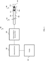
- the system 100 includes an intravascular device 110 having a sensor assemblies 112 and 116, a computing device 120, a patient interface module (PIM) 122, and a display 130.
- the intravascular sensing system 100 can be implemented, for example, in a catheterization lab of a hospital or other medical services provider.
- the intravascular device 110 is also illustrated in more detail in FIG. 2 .
- the intravascular device 110 includes flexible elongate member 106 and sensor assemblies 112, 116.
- the intravascular device 110 is configured to be inserted into a patient's vasculature by a user, such as a surgeon or other medical profession, during an intravascular sensing procedure.
- the intravascular device 110 can be a catheter, guide wire, or guide catheter.
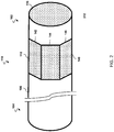
- the flexible elongate member 106 has a distal portion 102 and a proximal portion 104.
- the dimensions of the flexible elongate member 106, including the length and diameter, can vary in different embodiments.
- the flexible elongate member 106 can be sized and shaped for use in the coronary arteries, peripheral vessels, heart, and/or other areas of the patient's vasculature.
- the intravascular device 110 can include one, two, three, four, or more sensor assemblies coupled to the flexible elongate member 106.
- FIGs. 1 and 2 illustrate two sensor assemblies 112, 116 disposed at the distal portion 102 of the intravascular device 110.
- Each sensor assembly 112, 116 includes an array or plurality of CMUTs.
- each array can be arranged in a planar, non-planar, and/or other suitable configuration.
- an array can include CMUTs laid out substantially in two dimensions (as shown, e.g., in FIG. 4 ).
- An array can also be arranged in a non-planar configuration.
- an array with CMUTs laid out substantially in two dimensions can be arranged in a cylindrical or non-planar configuration when wrapped around an intravascular device (e.g., sensor assembly 112 of FIGs. 1 and 2 ). It is understood that a CMUT array can be described as two-dimensional or three-dimensional. In that regard, an array with CMUTs laid out substantially in two dimensions (x and y) extends at least some value in the third dimension (z). Other suitable two-dimensional or three-dimensional configurations are also contemplated.
- each CMUT includes a sensor membrane or diaphragm 140 that is configured to be deflected upon application of voltage to create a pressure wave (e.g., to transmit an ultrasound signal) or detect/measure pressure that is electronically sensed as a change in capacitance (e.g., upon receipt of an ultrasound echo).
- the CMUTs can be similar to those described in U.S. Patent No. 8,203,912 , titled "CMUTs with a high-k dielectric," and issued June 19, 2012; U.S. Patent No.
- the sensor assemblies 112, 116 can be positioned, arranged, oriented, and/or otherwise disposed on the flexible elongate member 106 in any desired manner.
- the sensor assemblies 112, 116 can be positioned at any point along the length of the flexible elongate member 106.
- the sensor assemblies 112, 116 can include a linear, rectangular, circular, elliptical, annular, and/otherwise suitably shaped array of CMUTs.
- the sensor assemblies 112, 116 may be coupled to the flexible elongate member 106 in a side-looking, forward-looking, other suitable orientation, and/or combinations thereof.
- the sensor assembly 112 is disposed in an annular configuration around or about the flexible elongate member 106.
- the sensor assembly 112 can be disposed in a side-looking orientation that covers the field of view 114, for example. In that regard, the sensor assembly 112 may be advantageously positioned for obtaining intravascular imaging and/or pressure data.
- the sensor assembly 116 is disposed at the distal end of the flexible elongate member 106.
- the sensor assembly 116 is disposed in a forward-looking orientation that covers the field of view 118, for example. In that regard, the sensor assembly 116 may be advantageously positioned for obtaining intravascular imaging, pressure data, and/or flow data.
- two or more sensor assemblies can be coupled to the flexible elongate member 106 with known separation distance(s) (e.g., 10 cm, 20 cm, etc.).
- the first and second sensor assemblies can be separated by a first distance, and the first and third sensor assemblies can be separated by a second distance.
- the sensor assemblies may be advantageously utilized for sensing pressure to compute one or more pressure quantities (iFR, FFR, Pd/Pa, etc.).
- a first sensor assembly can be positioned at a location proximal to a lesion (e.g. at or near the aorta, with a coronary artery, etc.), and the second and third sensor assemblies can be positioned at locations distal to the lesion.
- the sensor assemblies can thus measure a proximal pressure (e.g., Pa) and two distal pressures (e.g., Pd 1 , Pd 2 , at different distances from the proximal pressure measurement location), for example, while the intravascular device is held stationary within the vasculature.
- a proximal pressure e.g., Pa
- two distal pressures e.g., Pd 1 , Pd 2 , at different distances from the proximal pressure measurement location
- Sensor assemblies 112, 116 can be substantially unitary components or formed of constituent elements.
- the sensor assembly 116 can be a single component.
- the sensor assembly 112 can include a plurality of panels 142, 144, 146.
- the sensor assembly 112 can include other panels on the side of the intravascular device 110 that is not visible in FIGs. 1 and 2 .
- the panels 142, 144, 146 are shown to be generally rectangular, though they may be otherwise shaped in different embodiments.
- the sensor assembly 112 can be manufactured with the panels 142, 144, 146 in the planar configuration. During assembly of the intravascular device 110, the panels 142, 144, 146 can be folded into an annular configuration.
- the sensor assembly 116 may be operated in a similar manner as a solid-state or phased array piezoelectric transducer array if so desired by the user.
- individual panels may be activated one at a time in a sweeping manner (e.g., to transmit ultrasound signal, to receive ultrasound signal, etc.).
- the sensor assemblies 112, 116 are configured to sense, collect, and/or otherwise obtain imaging data, pressure data, Doppler or velocity flow data, volume or mass flow data, temperature data, other diagnostic data, and/or combinations thereof.
- the sensor assembly 112 and the sensor assembly 116 are operable to obtain different types or modalities of intravascular data.
- the sensor assembly 112 obtains pressure data while the sensor assembly 116 obtains flow data.
- the sensor assembly 112 and/or the sensor assembly 116 may each be fixedly configured to obtain one type of intravascular data.
- the sensor assembly 112 and/or the sensor assembly 116 can be optimized, e.g., during manufacture, to obtain data associated with a particular intravascular modality.
- the sensor assemblies 112, 116 are operable to obtain data associated with the same intravascular modality.
- the sensor assembly 112 and/or the sensor assembly may be variably configured to obtain data associated with different intravascular modalities.
- the sensor assemblies 112, 116 are operable to obtain any one or more intravascular sensing modalities.
- the sensor assembly 112 can obtain pressure data and later obtain flow data.
- the data type obtained by the sensor assemblies 112, 116 can be selected and controlled by a user (e.g., before and/or during the intravascular sensing procedure).
- one of the sensor assembly 112 and/or the sensor assembly 116 is fixedly configured to obtain one type of intravascular data while the other of the sensor assembly 112 and/or the sensor assembly 116 is variably configured to obtain different types of intravascular data.
- different portions of the array of CMUTs forming the sensor assembly are operable to obtain intravascular data associated with different modalities.
- a portion of the CMUT array can be configured to obtain imaging data
- a portion can be configured to obtain pressure data
- a portion may be configured to obtain flow data
- the different portions of the sensor assembly can each be fixedly configured to obtain one type of intravascular data. In that regard, the different portions may be optimized, e.g., during manufacture, to obtain the respective data type.
- the different portions of the CMUT array can each variably configured to obtain different types of intravascular data.
- a first portion of the CMUT array can obtain pressure data and later obtain flow data.
- the data type obtained by different portions of the CMUT array can be selected and controlled by a user (e.g., before and/or during the intravascular sensing procedure).
- the intravascular device 110 can include various other components to facilitate transmission of signals between the sensor assemblies 112, 116, the computing device 120, and/or the PIM 122.
- the intravascular device 110 can include conductors that electrically couple the sensor assemblies 112, 116, the computing device 120, and/or the PIM 122.
- the conductors may be in contact with electrodes of the CMUT, a particular portion of the CMUT array, and/or the sensor assemblies 112, 116.
- the intravascular device 110 can also include integrated circuit controller chips(s) or application-specific integrated circuit(s) configured to control the sensor assemblies 112, 116 and/or particular portions thereof.
- controller chip(s) may activate transmitter circuitry to generate an electrical pulse to excite the CMUT array element(s) and to accept amplified echo signals received from the CMUT array element(s) via amplifiers included on the controller chip(s).
- the controller chip(s) can also provide to signals to the sensor assemblies 112, 116 and/or portions thereof to obtain data associated with particular intravascular sensing modalities.
- controller chip(s) may be configured to perform pre-processing on the obtained data to determine the modality associated therewith.
- controller chip(s) can perform digital signal processing functions, amplifier functions, wireless functions, as described, e.g., in U.S. Application No. 14/133,331 , titled "Intravascular Devices Having Information Stored Thereon And/Or Wireless Communication Functionality, Including Associated Devices, Systems, And Methods," and filed December 18, 2013.
- the intravascular device 110 and/or the sensor assemblies 112, 116 are in communication the computing device 120 and/or the PIM 122.
- the computing device 120 receives the intravascular data obtained by the intravascular device 110 and processes the intravascular data to generate a graphical representation of the obtained data.
- the computing device 120 can receive pressure data from the sensor assembly 112 and/or the sensor assembly 116 by way of the PIM 122.
- the computing device 120 can process the data to compute one or more pressure quantities (e.g., FFR, iFR, etc.).
- the computing device 120 can co-register the obtained data with a fluoroscopic/angiographic image of the vessel.
- the computing device 120 can output a graphical representation of the processed data, such as the pressure quantities overlaid on the image of the vessel to the display 130.
- the computing device 120 can receive imaging data representative of ultrasound echoes from the sensor assembly 112 and/or the sensor assembly 116.
- the computing device 120 can process the data to reconstruct an image of the tissue structures in the medium surrounding the sensor assembly 112 and/or the sensor assembly 116.
- the image provided to and displayed on the display 130 can be similar to a B-scan image representative of the two-dimensional anatomical structure of the tissue in a plane perpendicular to the longitudinal axis of intravascular device 110, with brightness at any point of the image representing of the strength of the echo signal received from the corresponding location within the tissue.
- the imaging data obtained by the intravascular device 110 is used for lumen mapping.
- the computing device 120 can receive and process the imaging data to generate an image illustrating the contours of a lumen of the patient's vasculature.
- the computing device 120 can receive and process flow data to generate a visual representation of movement of elements in the medium surrounding the sensor assembly 112 and/or the sensor assembly 116, such as blood flow.
- the computing device 120 may carry out one or more functions described above with respect to the controller chip(s).
- the computing device 120 can generate and provide signals to the sensor assemblies 112, 116 and/or portions thereof to obtain data associated with particular intravascular sensing modalities.
- the computing device 120 can be generally representative of any device suitable for performing the processing and analysis techniques discussed within the present disclosure.
- the computing device 120 includes a processor, random access memory, and a storage medium.
- the computing device 120 is operable to execute steps associated with the data acquisition and analysis described herein. Accordingly, it is understood that any steps related to data acquisition, data processing, instrument control, and/or other processing or control aspects of the present disclosure may be implemented by the computing device using corresponding instructions stored on or in a non-transitory computer readable medium accessible by the computing device.
- the computing device 120 is a console device.
- the computing device 120 is similar to the s5TM Imaging System or the s5iTM Imaging System, each available from Volcano Corporation.
- the computing device 120 is portable (e.g., handheld, on a rolling cart, etc.). Further, it is understood that in some instances the computing device 120 comprises a plurality of computing devices. In that regard, it is particularly understood that the different processing and/or control aspects of the present disclosure may be implemented separately or within predefined groupings using a plurality of computing devices. Any divisions and/or combinations of the processing and/or control aspects described below across multiple computing devices are within the scope of the present disclosure.
- the PIM 122 that facilitates communication of signals between the computing device 120 and the sensor assemblies 112, 116 of the intravascular device 110.
- the PIM 122 performs preliminary processing of the obtained intravascular data prior to relaying the data to the computing device 120.
- the PIM 122 performs amplification, filtering, and/or aggregating of the data.
- the PIM 122 also supplies high- and low-voltage DC power to support operation of the intravascular device 110 including circuitry within the sensor assemblies 112, 116.
- the PIM 122 transfers the received intravascular data to the computing device 120 where, among other things, a graphical presentation of the processed data is generated displayed on the display 130.
- the PIM 122 is configured to perform wireless functions related to, e.g., the transmission and receipt of intravascular data.
- An exemplary PIM is described, for example, in U.S. Application No. 14/133,406 , titled “Wireless Interface Devices, Systems, and Methods for Use with Intravascular Pressure Monitoring Devices,” and filed December 18, 2013.
- CMUT array 300 shown therein is a top view of a CMUT array 300.
- the array 300 can comprise an entire or partial sensor assembly.
- the CMUT array 300 may be the sensor assembly 112 or an individual panel 142, 144, 146 ( FIG. 2 ).
- the CMUT array 300 includes a plurality of sensor membranes 340.
- the size of the sensor membranes 340 is not necessarily to scale in the drawings.
- the diameter of each of the sensor membranes 340 can be between approximately 1 ⁇ m and approximately 200 ⁇ m, between approximately 10 ⁇ m and approximately 200 ⁇ m, between approximately 20 ⁇ m and approximately 200 ⁇ m, and/or other suitable values both larger and smaller.
- different portions or zones of the CMUT array 300 are operable to obtain data associated with different intravascular modalities.
- zone 352 can be configured to obtain pressure data
- zone 354 can be configured to obtain flow data
- zone 356 can be configured to obtain imaging data. That is, different portions of the CMUT array 300 comprise the pressure sensor, the flow sensor, and/or the imaging sensor. While the zones 352, 354, 356 are shown to be similarly sized and shaped, it is understood that the zones may be sized and shaped differently from one another. Similarly, the illustrated embodiment illustrates rectangular zones. In various embodiments, other shapes, such as circles, ellipses, polygons, etc. are used to define the zones.
- individual CMUTs and/or zones that perform the same function are arranged continuously or continuously in an array.
- individual CMUTs and/or zones that are spaced from one another (e.g., discontinuous or discontinuous) in an array perform the same function.
- a computing device can process the intravascular data collected at different zones to generate a composite.
- the individual zones can be described as individual pressure sensors, flow sensors, and/or imaging sensors.
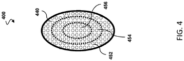
- CMUT array 400 is similarly in manner respects to the CMUT array 300 ( FIG. 3 ).
- the array 400 can comprise an entire or partial sensor assembly.
- the CMUT array 300 may be the sensor assembly 116 ( FIG. 2 ).
- the CMUT array 400 includes a plurality of sensor membranes 440.
- different portions or zones of the CMUT array 400 are operable to obtain data associated different intravascular modalities.
- zone 452 can be configured to obtain pressure data
- zone 454 can be configured to obtain flow data
- zone 456 can be configured to obtain imaging data.
- CMUT array 400 different portions of the CMUT array 400 comprise the pressure sensor, the flow sensor, or the imaging sensor.
- the zone 456 is circular while the zones 452 and 454 are annular, ring, or donut shaped.
- the zones 452, 454, 456 are also concentric. It is understood that the zones may be sized and shaped differently in various embodiments.
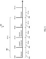
- the protocol 500 is representative of one sensor assembly comprising the pressure sensor, the flow sensor, and/or the imaging sensor at different times. By rapidly cycling through different functions of the sensor assembly, the same sensor assembly can be utilized to obtain data associated with multiple intravascular modalities.
- the protocol 500 may be implemented using the sensor assembly 112 and/or the sensor assembly 116 ( FIGs. 1 and 2 ).
- the protocol 500 includes intervals 570, 572, 574, 576, 578 during which the sensor assembly performs different functions.
- the intervals 570, 572, 574, 576, 578 are shown to each be 10 ms in the illustrated embodiment. It is understood that the duration of the intervals 570, 572, 574, 576, 578 may be different in other embodiments. Similarly, it is understand that one or more intervals 570, 572, 574, 576, 578 can have a duration that is longer or shorter than one or more other intervals 570, 572, 574, 576, 578.
- the sensor assembly is operable to obtain pressure data.
- the intervals 572, 574 can be associated with imaging data.
- the sensor assembly is operable to transmit ultrasound waves, and during the interval 574, the sensor assembly is operable to receive ultrasound echoes reflected from tissues structures within the patient's vascular. During the interval 576, the sensor assembly is operable to obtain flow data.
- the cycle 560 can repeat multiple times for the total duration of the sensing procedure.
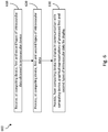
- FIG. 6 illustrates a flowchart of a method 600 of obtaining intravascular data.
- the method 600 includes a number of enumerated steps, but implementations of the method 600 may include additional steps before, after, and in between the enumerated steps. In some implementations, one or more of the enumerated steps may be omitted or performed in a different order.
- the steps of the method 600 may be performed by processor, such as the computing device 120 ( FIG. 1 ).
- the method 600 includes receiving, at a computing device, first and second intravascular data associated with different modalities.
- the first and second intravascular data is obtained by an intravascular device inserted into the vasculature of a patient.
- the intravascular device is in communication with the computing device.
- the intravascular device may similar to the intravascular device 110 ( FIGs. 1 and 2 ), including a flexible elongate member having a proximal portion and a distal portion, and a sensor assembly disposed at the distal portion of the flexible elongate member.
- the sensor assembly can include an array of CMUTs.
- the sensor assembly comprises or is operable to perform the functions of at least two of a pressure sensor, a flow sensor, or an imaging sensor.
- the first and second intravascular data are simultaneously obtained by the intravascular device.
- different portions of the array of CMUTs can comprise or operate as different ones of the pressure sensor, the flow sensor, or the imaging sensor.
- the method 600 can include controlling the respective different portions of the array of CMUTs to obtain pressure data, flow data, or imaging data.
- the first and second intravascular data are obtained by the intravascular device at different times.
- the sensor assembly can comprise or operate as different ones of the pressure sensor, the flow sensor, or the imaging sensor at different times.
- the method 600 can include controlling the sensor assembly to obtain pressure data, flow data, or imaging data at the respective different times.
- the method 600 includes processing, at the computing device, the first and second intravascular data.
- Processing the first and second intravascular data can include or more computational steps to filter, analyze, and/or otherwise manipulate the obtained data.
- processing the first and second intravascular data can include determining an intravascular modality associated with the first and second intravascular data.
- the method 600 includes providing, from the computing device to a display in communication with the computing device, graphical representations of the processed first and second types of intravascular data for display.
- the graphical representations can include images of the patient's vasculature, quantities, colors, shading, and/or other suitable information representative of the processed data.
Landscapes
- Health & Medical Sciences (AREA)
- Life Sciences & Earth Sciences (AREA)
- Engineering & Computer Science (AREA)
- Medical Informatics (AREA)
- Surgery (AREA)
- Pathology (AREA)
- Radiology & Medical Imaging (AREA)
- Biophysics (AREA)
- Biomedical Technology (AREA)
- Heart & Thoracic Surgery (AREA)
- Physics & Mathematics (AREA)
- Molecular Biology (AREA)
- Nuclear Medicine, Radiotherapy & Molecular Imaging (AREA)
- Animal Behavior & Ethology (AREA)
- General Health & Medical Sciences (AREA)
- Public Health (AREA)
- Veterinary Medicine (AREA)
- Hematology (AREA)
- Gynecology & Obstetrics (AREA)
- Mechanical Engineering (AREA)
- Ultra Sonic Daignosis Equipment (AREA)
- Measuring Pulse, Heart Rate, Blood Pressure Or Blood Flow (AREA)
Applications Claiming Priority (2)
| Application Number | Priority Date | Filing Date | Title |
|---|---|---|---|
| US201562188222P | 2015-07-02 | 2015-07-02 | |
| PCT/IB2016/053645 WO2017001965A1 (en) | 2015-07-02 | 2016-06-20 | Multi-mode capacitive micromachined ultrasound transducer and associated devices, systems, and methods |
Publications (2)
| Publication Number | Publication Date |
|---|---|
| EP3316791A1 EP3316791A1 (en) | 2018-05-09 |
| EP3316791B1 true EP3316791B1 (en) | 2020-08-05 |
Family
ID=56203447
Family Applications (1)
| Application Number | Title | Priority Date | Filing Date |
|---|---|---|---|
| EP16731985.4A Active EP3316791B1 (en) | 2015-07-02 | 2016-06-20 | Multi-mode capacitive micromachined ultrasound transducer and associated devices and systems |
Country Status (5)
| Country | Link |
|---|---|
| US (2) | US11766237B2 (enExample) |
| EP (1) | EP3316791B1 (enExample) |
| JP (1) | JP6932085B2 (enExample) |
| CN (1) | CN107735032B (enExample) |
| WO (1) | WO2017001965A1 (enExample) |
Families Citing this family (10)
| Publication number | Priority date | Publication date | Assignee | Title |
|---|---|---|---|---|
| US11135454B2 (en) | 2015-06-24 | 2021-10-05 | The Regents Of The University Of Michigan | Histotripsy therapy systems and methods for the treatment of brain tissue |
| EP3388155A1 (en) * | 2017-04-13 | 2018-10-17 | Koninklijke Philips N.V. | Ultrasound transducer probe with a faceted distal front surface |
| CN111212606B (zh) * | 2017-08-15 | 2024-03-01 | 皇家飞利浦有限公司 | 频率可调谐血管内超声设备 |
| CN109350124A (zh) * | 2018-11-22 | 2019-02-19 | 苏州科技城医院 | 基于超声换能器的微创式血管连续测压系统 |
| AU2019389001B2 (en) | 2018-11-28 | 2025-08-14 | Histosonics, Inc. | Histotripsy systems and methods |
| EP3943013A1 (en) * | 2020-07-24 | 2022-01-26 | Koninklijke Philips N.V. | Device and system device for ultrasound imaging and pressure sensing |
| IL300851A (en) | 2020-08-27 | 2023-04-01 | Univ Michigan Regents | Ultrasonic transducer with transmit-receive capability for focused ultrasound |
| CN113081045A (zh) * | 2021-04-20 | 2021-07-09 | 天津市胸科医院 | 一种血管内前视探测装置 |
| AU2023366591A1 (en) | 2022-10-28 | 2025-04-24 | Histosonics, Inc. | Histotripsy systems and methods |
| WO2024221001A2 (en) | 2023-04-20 | 2024-10-24 | Histosonics, Inc. | Histotripsy systems and associated methods including user interfaces and workflows for treatment planning and therapy |
Family Cites Families (30)
| Publication number | Priority date | Publication date | Assignee | Title |
|---|---|---|---|---|
| US6443901B1 (en) | 2000-06-15 | 2002-09-03 | Koninklijke Philips Electronics N.V. | Capacitive micromachined ultrasonic transducers |
| US20060100530A1 (en) * | 2000-11-28 | 2006-05-11 | Allez Physionix Limited | Systems and methods for non-invasive detection and monitoring of cardiac and blood parameters |
| US6659954B2 (en) | 2001-12-19 | 2003-12-09 | Koninklijke Philips Electronics Nv | Micromachined ultrasound transducer and method for fabricating same |
| US7303530B2 (en) * | 2003-05-22 | 2007-12-04 | Siemens Medical Solutions Usa, Inc. | Transducer arrays with an integrated sensor and methods of use |
| US7125383B2 (en) * | 2003-12-30 | 2006-10-24 | General Electric Company | Method and apparatus for ultrasonic continuous, non-invasive blood pressure monitoring |
| US8043216B2 (en) * | 2004-06-09 | 2011-10-25 | Hitachi Medical Corporation | Method of displaying elastic image and diagnostic ultrasound system |
| US20080221448A1 (en) * | 2007-03-07 | 2008-09-11 | Khuri-Yakub Butrus T | Image-guided delivery of therapeutic tools duing minimally invasive surgeries and interventions |
| US8203912B2 (en) | 2007-07-31 | 2012-06-19 | Koninklijke Philips Electronics N.V. | CMUTs with a high-k dielectric |
| WO2009037655A2 (en) | 2007-09-17 | 2009-03-26 | Koninklijke Philips Electronics, N.V. | Production of pre-collapsed capacitive micro-machined ultrasonic transducers and applications thereof |
| US9895158B2 (en) * | 2007-10-26 | 2018-02-20 | University Of Virginia Patent Foundation | Method and apparatus for accelerated disintegration of blood clot |
| EP2215854A1 (en) * | 2007-12-03 | 2010-08-11 | Kolo Technologies, Inc. | Stacked transducing devices |
| EP2214560A1 (en) * | 2007-12-03 | 2010-08-11 | Kolo Technologies, Inc. | Cmut packaging for ultrasound system |
| BRPI0822064A2 (pt) * | 2007-12-10 | 2015-06-23 | Stc Unm | Dispositivos de imageamento fotoacústico e métodos de imageamento |
| EP2281188A4 (en) * | 2008-05-30 | 2015-09-23 | Stc Unm | PHOTOACOUSTIC IMAGING DEVICES AND METHODS OF MAKING AND USING THE SAME |
| US9132693B2 (en) | 2008-09-16 | 2015-09-15 | Koninklijke Philps N.V. | Capacitive micromachine ultrasound transducer |
| JP5499939B2 (ja) * | 2010-06-25 | 2014-05-21 | セイコーエプソン株式会社 | 測定装置、生体検査装置、流速測定方法、および圧力測定方法 |
| EP2455133A1 (en) | 2010-11-18 | 2012-05-23 | Koninklijke Philips Electronics N.V. | Catheter comprising capacitive micromachined ultrasonic transducers with an adjustable focus |
| JP5961246B2 (ja) | 2011-03-22 | 2016-08-02 | コーニンクレッカ フィリップス エヌ ヴェKoninklijke Philips N.V. | 基板に対して抑制された音響結合を持つ超音波cmut |
| JP6388536B2 (ja) | 2011-06-27 | 2018-09-12 | コーニンクレッカ フィリップス エヌ ヴェKoninklijke Philips N.V. | 超音波振動子アセンブリ及びその製造方法 |
| BR112014014911A2 (pt) | 2011-12-20 | 2017-06-13 | Koninklijke Philips Nv | dispositivo transdutor de ultrassom; e método de fabricação de um dispositivo transdutor de ultrassom |
| CN104066521B (zh) | 2012-01-27 | 2017-07-11 | 皇家飞利浦有限公司 | 电容式微机械换能器及制造所述电容式微机械换能器的方法 |
| BR112014018080A8 (pt) | 2012-01-27 | 2017-07-11 | Koninklijke Philips Nv | Método de fabricação de um transdutor microusinado capacitivo, e, transdutor microusinado capacitivo |
| JP6329491B2 (ja) | 2012-03-13 | 2018-05-23 | コーニンクレッカ フィリップス エヌ ヴェKoninklijke Philips N.V. | 荷電電圧源を有する容量性マイクロマシン加工超音波トランスデューサ装置 |
| EP2836275B1 (en) * | 2012-04-12 | 2021-01-27 | Koninklijke Philips N.V. | High intensity focused ultrasound with capacitive micromachined transducers |
| EP4042936A1 (en) | 2012-12-21 | 2022-08-17 | Philips Image Guided Therapy Corporation | Wireless interface devices, and systems for use with intravascular pressure monitoring devices |
| CA2895975A1 (en) * | 2012-12-21 | 2014-06-26 | Volcano Corporation | Display control for a multi-sensor medical device |
| US20140187978A1 (en) | 2012-12-28 | 2014-07-03 | Volcano Corporation | Intravascular Devices Having Information Stored Thereon And/Or Wireless Communication Functionality, Including Associated Devices, Systems, And Methods |
| US9259206B2 (en) * | 2013-02-20 | 2016-02-16 | Georgia Tech Research Corporation | CMUT-on-CMOS based guidewire intravascular imaging |
| WO2014151841A1 (en) * | 2013-03-15 | 2014-09-25 | Volcano Corporation | Universal patient interface module and associated devices, systems, and methods |
| US20150086098A1 (en) * | 2013-09-26 | 2015-03-26 | Volcano Corporation | Systems and methods for producing intravascular images |
-
2016
- 2016-06-20 EP EP16731985.4A patent/EP3316791B1/en active Active
- 2016-06-20 CN CN201680039206.2A patent/CN107735032B/zh active Active
- 2016-06-20 WO PCT/IB2016/053645 patent/WO2017001965A1/en not_active Ceased
- 2016-06-20 JP JP2017567401A patent/JP6932085B2/ja not_active Expired - Fee Related
- 2016-06-20 US US15/741,473 patent/US11766237B2/en active Active
-
2023
- 2023-09-21 US US18/371,388 patent/US20240023930A1/en not_active Abandoned
Non-Patent Citations (1)
| Title |
|---|
| None * |
Also Published As
| Publication number | Publication date |
|---|---|
| US20240023930A1 (en) | 2024-01-25 |
| EP3316791A1 (en) | 2018-05-09 |
| US20180360414A1 (en) | 2018-12-20 |
| CN107735032B (zh) | 2021-09-21 |
| JP2018519080A (ja) | 2018-07-19 |
| JP6932085B2 (ja) | 2021-09-08 |
| WO2017001965A1 (en) | 2017-01-05 |
| CN107735032A (zh) | 2018-02-23 |
| US11766237B2 (en) | 2023-09-26 |
Similar Documents
| Publication | Publication Date | Title |
|---|---|---|
| US20240023930A1 (en) | Multi-mode capacitive micromachined ultrasound transducer and associated devices, systems, and methods for multiple different intravascular sensing capabilities | |
| US10512449B2 (en) | Intravascular device for vessel measurement and associated systems, devices, and methods | |
| US20230293149A1 (en) | Phased array intravascular devices, systems, and methods utilizing photoacoustic and ultrasound techniques` | |
| CN110352039B (zh) | 一种智能超声系统 | |
| US11395638B2 (en) | Interleaved transmit sequences and motion estimation in ultrasound images, and associated systems, devices, and methods | |
| CN112603273A (zh) | 具有用于成像和压力感测的集成控制器的导管 | |
| US12383225B2 (en) | Intravascular ultrasound patient interface module (PIM) for distributed wireless intraluminal imaging systems | |
| JP2020537569A (ja) | 超音波撮像システム及び方法 | |
| US12201474B2 (en) | Tissue and vascular pathway mapping using synchronized photoacoustic and ultrasound pullback techniques | |
| US11559207B2 (en) | Rotational intravascular devices, systems, and methods utilizing photoacoustic and ultrasound imaging techniques | |
| JP2016538004A (ja) | 血管内画像を生成するためのシステム及び方法 | |
| US20200297313A1 (en) | Tissue and vascular pathway mapping utilizing photoacoustic and ultrasound techniques |
Legal Events
| Date | Code | Title | Description |
|---|---|---|---|
| STAA | Information on the status of an ep patent application or granted ep patent |
Free format text: STATUS: THE INTERNATIONAL PUBLICATION HAS BEEN MADE |
|
| PUAI | Public reference made under article 153(3) epc to a published international application that has entered the european phase |
Free format text: ORIGINAL CODE: 0009012 |
|
| STAA | Information on the status of an ep patent application or granted ep patent |
Free format text: STATUS: REQUEST FOR EXAMINATION WAS MADE |
|
| 17P | Request for examination filed |
Effective date: 20180202 |
|
| AK | Designated contracting states |
Kind code of ref document: A1 Designated state(s): AL AT BE BG CH CY CZ DE DK EE ES FI FR GB GR HR HU IE IS IT LI LT LU LV MC MK MT NL NO PL PT RO RS SE SI SK SM TR |
|
| AX | Request for extension of the european patent |
Extension state: BA ME |
|
| DAV | Request for validation of the european patent (deleted) | ||
| DAX | Request for extension of the european patent (deleted) | ||
| GRAP | Despatch of communication of intention to grant a patent |
Free format text: ORIGINAL CODE: EPIDOSNIGR1 |
|
| STAA | Information on the status of an ep patent application or granted ep patent |
Free format text: STATUS: GRANT OF PATENT IS INTENDED |
|
| INTG | Intention to grant announced |
Effective date: 20200123 |
|
| RAP1 | Party data changed (applicant data changed or rights of an application transferred) |
Owner name: KONINKLIJKE PHILIPS N.V. |
|
| GRAS | Grant fee paid |
Free format text: ORIGINAL CODE: EPIDOSNIGR3 |
|
| GRAA | (expected) grant |
Free format text: ORIGINAL CODE: 0009210 |
|
| STAA | Information on the status of an ep patent application or granted ep patent |
Free format text: STATUS: THE PATENT HAS BEEN GRANTED |
|
| AK | Designated contracting states |
Kind code of ref document: B1 Designated state(s): AL AT BE BG CH CY CZ DE DK EE ES FI FR GB GR HR HU IE IS IT LI LT LU LV MC MK MT NL NO PL PT RO RS SE SI SK SM TR |
|
| REG | Reference to a national code |
Ref country code: GB Ref legal event code: FG4D |
|
| REG | Reference to a national code |
Ref country code: CH Ref legal event code: EP |
|
| REG | Reference to a national code |
Ref country code: AT Ref legal event code: REF Ref document number: 1297591 Country of ref document: AT Kind code of ref document: T Effective date: 20200815 |
|
| REG | Reference to a national code |
Ref country code: DE Ref legal event code: R096 Ref document number: 602016041342 Country of ref document: DE |
|
| REG | Reference to a national code |
Ref country code: IE Ref legal event code: FG4D |
|
| REG | Reference to a national code |
Ref country code: LT Ref legal event code: MG4D |
|
| REG | Reference to a national code |
Ref country code: NL Ref legal event code: MP Effective date: 20200805 |
|
| REG | Reference to a national code |
Ref country code: AT Ref legal event code: MK05 Ref document number: 1297591 Country of ref document: AT Kind code of ref document: T Effective date: 20200805 |
|
| PG25 | Lapsed in a contracting state [announced via postgrant information from national office to epo] |
Ref country code: LT Free format text: LAPSE BECAUSE OF FAILURE TO SUBMIT A TRANSLATION OF THE DESCRIPTION OR TO PAY THE FEE WITHIN THE PRESCRIBED TIME-LIMIT Effective date: 20200805 Ref country code: HR Free format text: LAPSE BECAUSE OF FAILURE TO SUBMIT A TRANSLATION OF THE DESCRIPTION OR TO PAY THE FEE WITHIN THE PRESCRIBED TIME-LIMIT Effective date: 20200805 Ref country code: FI Free format text: LAPSE BECAUSE OF FAILURE TO SUBMIT A TRANSLATION OF THE DESCRIPTION OR TO PAY THE FEE WITHIN THE PRESCRIBED TIME-LIMIT Effective date: 20200805 Ref country code: PT Free format text: LAPSE BECAUSE OF FAILURE TO SUBMIT A TRANSLATION OF THE DESCRIPTION OR TO PAY THE FEE WITHIN THE PRESCRIBED TIME-LIMIT Effective date: 20201207 Ref country code: SE Free format text: LAPSE BECAUSE OF FAILURE TO SUBMIT A TRANSLATION OF THE DESCRIPTION OR TO PAY THE FEE WITHIN THE PRESCRIBED TIME-LIMIT Effective date: 20200805 Ref country code: ES Free format text: LAPSE BECAUSE OF FAILURE TO SUBMIT A TRANSLATION OF THE DESCRIPTION OR TO PAY THE FEE WITHIN THE PRESCRIBED TIME-LIMIT Effective date: 20200805 Ref country code: GR Free format text: LAPSE BECAUSE OF FAILURE TO SUBMIT A TRANSLATION OF THE DESCRIPTION OR TO PAY THE FEE WITHIN THE PRESCRIBED TIME-LIMIT Effective date: 20201106 Ref country code: NO Free format text: LAPSE BECAUSE OF FAILURE TO SUBMIT A TRANSLATION OF THE DESCRIPTION OR TO PAY THE FEE WITHIN THE PRESCRIBED TIME-LIMIT Effective date: 20201105 Ref country code: BG Free format text: LAPSE BECAUSE OF FAILURE TO SUBMIT A TRANSLATION OF THE DESCRIPTION OR TO PAY THE FEE WITHIN THE PRESCRIBED TIME-LIMIT Effective date: 20201105 Ref country code: AT Free format text: LAPSE BECAUSE OF FAILURE TO SUBMIT A TRANSLATION OF THE DESCRIPTION OR TO PAY THE FEE WITHIN THE PRESCRIBED TIME-LIMIT Effective date: 20200805 |
|
| PG25 | Lapsed in a contracting state [announced via postgrant information from national office to epo] |
Ref country code: RS Free format text: LAPSE BECAUSE OF FAILURE TO SUBMIT A TRANSLATION OF THE DESCRIPTION OR TO PAY THE FEE WITHIN THE PRESCRIBED TIME-LIMIT Effective date: 20200805 Ref country code: PL Free format text: LAPSE BECAUSE OF FAILURE TO SUBMIT A TRANSLATION OF THE DESCRIPTION OR TO PAY THE FEE WITHIN THE PRESCRIBED TIME-LIMIT Effective date: 20200805 Ref country code: NL Free format text: LAPSE BECAUSE OF FAILURE TO SUBMIT A TRANSLATION OF THE DESCRIPTION OR TO PAY THE FEE WITHIN THE PRESCRIBED TIME-LIMIT Effective date: 20200805 Ref country code: LV Free format text: LAPSE BECAUSE OF FAILURE TO SUBMIT A TRANSLATION OF THE DESCRIPTION OR TO PAY THE FEE WITHIN THE PRESCRIBED TIME-LIMIT Effective date: 20200805 Ref country code: IS Free format text: LAPSE BECAUSE OF FAILURE TO SUBMIT A TRANSLATION OF THE DESCRIPTION OR TO PAY THE FEE WITHIN THE PRESCRIBED TIME-LIMIT Effective date: 20201205 |
|
| PG25 | Lapsed in a contracting state [announced via postgrant information from national office to epo] |
Ref country code: EE Free format text: LAPSE BECAUSE OF FAILURE TO SUBMIT A TRANSLATION OF THE DESCRIPTION OR TO PAY THE FEE WITHIN THE PRESCRIBED TIME-LIMIT Effective date: 20200805 Ref country code: CZ Free format text: LAPSE BECAUSE OF FAILURE TO SUBMIT A TRANSLATION OF THE DESCRIPTION OR TO PAY THE FEE WITHIN THE PRESCRIBED TIME-LIMIT Effective date: 20200805 Ref country code: DK Free format text: LAPSE BECAUSE OF FAILURE TO SUBMIT A TRANSLATION OF THE DESCRIPTION OR TO PAY THE FEE WITHIN THE PRESCRIBED TIME-LIMIT Effective date: 20200805 Ref country code: RO Free format text: LAPSE BECAUSE OF FAILURE TO SUBMIT A TRANSLATION OF THE DESCRIPTION OR TO PAY THE FEE WITHIN THE PRESCRIBED TIME-LIMIT Effective date: 20200805 Ref country code: SM Free format text: LAPSE BECAUSE OF FAILURE TO SUBMIT A TRANSLATION OF THE DESCRIPTION OR TO PAY THE FEE WITHIN THE PRESCRIBED TIME-LIMIT Effective date: 20200805 |
|
| REG | Reference to a national code |
Ref country code: DE Ref legal event code: R097 Ref document number: 602016041342 Country of ref document: DE |
|
| PG25 | Lapsed in a contracting state [announced via postgrant information from national office to epo] |
Ref country code: AL Free format text: LAPSE BECAUSE OF FAILURE TO SUBMIT A TRANSLATION OF THE DESCRIPTION OR TO PAY THE FEE WITHIN THE PRESCRIBED TIME-LIMIT Effective date: 20200805 |
|
| PLBE | No opposition filed within time limit |
Free format text: ORIGINAL CODE: 0009261 |
|
| STAA | Information on the status of an ep patent application or granted ep patent |
Free format text: STATUS: NO OPPOSITION FILED WITHIN TIME LIMIT |
|
| PG25 | Lapsed in a contracting state [announced via postgrant information from national office to epo] |
Ref country code: SK Free format text: LAPSE BECAUSE OF FAILURE TO SUBMIT A TRANSLATION OF THE DESCRIPTION OR TO PAY THE FEE WITHIN THE PRESCRIBED TIME-LIMIT Effective date: 20200805 |
|
| 26N | No opposition filed |
Effective date: 20210507 |
|
| PG25 | Lapsed in a contracting state [announced via postgrant information from national office to epo] |
Ref country code: IT Free format text: LAPSE BECAUSE OF FAILURE TO SUBMIT A TRANSLATION OF THE DESCRIPTION OR TO PAY THE FEE WITHIN THE PRESCRIBED TIME-LIMIT Effective date: 20200805 |
|
| PGFP | Annual fee paid to national office [announced via postgrant information from national office to epo] |
Ref country code: FR Payment date: 20210625 Year of fee payment: 6 |
|
| PG25 | Lapsed in a contracting state [announced via postgrant information from national office to epo] |
Ref country code: SI Free format text: LAPSE BECAUSE OF FAILURE TO SUBMIT A TRANSLATION OF THE DESCRIPTION OR TO PAY THE FEE WITHIN THE PRESCRIBED TIME-LIMIT Effective date: 20200805 |
|
| PG25 | Lapsed in a contracting state [announced via postgrant information from national office to epo] |
Ref country code: MC Free format text: LAPSE BECAUSE OF FAILURE TO SUBMIT A TRANSLATION OF THE DESCRIPTION OR TO PAY THE FEE WITHIN THE PRESCRIBED TIME-LIMIT Effective date: 20200805 |
|
| REG | Reference to a national code |
Ref country code: CH Ref legal event code: PL |
|
| REG | Reference to a national code |
Ref country code: BE Ref legal event code: MM Effective date: 20210630 |
|
| PG25 | Lapsed in a contracting state [announced via postgrant information from national office to epo] |
Ref country code: LU Free format text: LAPSE BECAUSE OF NON-PAYMENT OF DUE FEES Effective date: 20210620 |
|
| PG25 | Lapsed in a contracting state [announced via postgrant information from national office to epo] |
Ref country code: LI Free format text: LAPSE BECAUSE OF NON-PAYMENT OF DUE FEES Effective date: 20210630 Ref country code: IE Free format text: LAPSE BECAUSE OF NON-PAYMENT OF DUE FEES Effective date: 20210620 Ref country code: CH Free format text: LAPSE BECAUSE OF NON-PAYMENT OF DUE FEES Effective date: 20210630 |
|
| PG25 | Lapsed in a contracting state [announced via postgrant information from national office to epo] |
Ref country code: BE Free format text: LAPSE BECAUSE OF NON-PAYMENT OF DUE FEES Effective date: 20210630 |
|
| PG25 | Lapsed in a contracting state [announced via postgrant information from national office to epo] |
Ref country code: FR Free format text: LAPSE BECAUSE OF NON-PAYMENT OF DUE FEES Effective date: 20220630 |
|
| PG25 | Lapsed in a contracting state [announced via postgrant information from national office to epo] |
Ref country code: CY Free format text: LAPSE BECAUSE OF FAILURE TO SUBMIT A TRANSLATION OF THE DESCRIPTION OR TO PAY THE FEE WITHIN THE PRESCRIBED TIME-LIMIT Effective date: 20200805 |
|
| PG25 | Lapsed in a contracting state [announced via postgrant information from national office to epo] |
Ref country code: HU Free format text: LAPSE BECAUSE OF FAILURE TO SUBMIT A TRANSLATION OF THE DESCRIPTION OR TO PAY THE FEE WITHIN THE PRESCRIBED TIME-LIMIT; INVALID AB INITIO Effective date: 20160620 |
|
| PG25 | Lapsed in a contracting state [announced via postgrant information from national office to epo] |
Ref country code: MK Free format text: LAPSE BECAUSE OF FAILURE TO SUBMIT A TRANSLATION OF THE DESCRIPTION OR TO PAY THE FEE WITHIN THE PRESCRIBED TIME-LIMIT Effective date: 20200805 |
|
| PG25 | Lapsed in a contracting state [announced via postgrant information from national office to epo] |
Ref country code: TR Free format text: LAPSE BECAUSE OF FAILURE TO SUBMIT A TRANSLATION OF THE DESCRIPTION OR TO PAY THE FEE WITHIN THE PRESCRIBED TIME-LIMIT Effective date: 20200805 |
|
| PG25 | Lapsed in a contracting state [announced via postgrant information from national office to epo] |
Ref country code: MT Free format text: LAPSE BECAUSE OF FAILURE TO SUBMIT A TRANSLATION OF THE DESCRIPTION OR TO PAY THE FEE WITHIN THE PRESCRIBED TIME-LIMIT Effective date: 20200805 |
|
| PGFP | Annual fee paid to national office [announced via postgrant information from national office to epo] |
Ref country code: DE Payment date: 20250626 Year of fee payment: 10 |
|
| PGFP | Annual fee paid to national office [announced via postgrant information from national office to epo] |
Ref country code: GB Payment date: 20250617 Year of fee payment: 10 |