EP3316756B2 - Vacuum cleaner - Google Patents
Vacuum cleaner Download PDFInfo
- Publication number
- EP3316756B2 EP3316756B2 EP17720154.8A EP17720154A EP3316756B2 EP 3316756 B2 EP3316756 B2 EP 3316756B2 EP 17720154 A EP17720154 A EP 17720154A EP 3316756 B2 EP3316756 B2 EP 3316756B2
- Authority
- EP
- European Patent Office
- Prior art keywords
- aggregate
- motor
- power setting
- rotation speed
- vacuum cleaner
- Prior art date
- Legal status (The legal status is an assumption and is not a legal conclusion. Google has not performed a legal analysis and makes no representation as to the accuracy of the status listed.)
- Active
Links
- 238000011144 upstream manufacturing Methods 0.000 claims description 13
- 238000013021 overheating Methods 0.000 claims description 10
- 238000001816 cooling Methods 0.000 description 15
- 239000012530 fluid Substances 0.000 description 4
- 230000001419 dependent effect Effects 0.000 description 2
- 239000000428 dust Substances 0.000 description 2
- 230000007423 decrease Effects 0.000 description 1
- 230000000694 effects Effects 0.000 description 1
- 238000005070 sampling Methods 0.000 description 1
Images
Classifications
-
- A—HUMAN NECESSITIES
- A47—FURNITURE; DOMESTIC ARTICLES OR APPLIANCES; COFFEE MILLS; SPICE MILLS; SUCTION CLEANERS IN GENERAL
- A47L—DOMESTIC WASHING OR CLEANING; SUCTION CLEANERS IN GENERAL
- A47L9/00—Details or accessories of suction cleaners, e.g. mechanical means for controlling the suction or for effecting pulsating action; Storing devices specially adapted to suction cleaners or parts thereof; Carrying-vehicles specially adapted for suction cleaners
- A47L9/28—Installation of the electric equipment, e.g. adaptation or attachment to the suction cleaner; Controlling suction cleaners by electric means
- A47L9/2889—Safety or protection devices or systems, e.g. for prevention of motor over-heating or for protection of the user
-
- A—HUMAN NECESSITIES
- A47—FURNITURE; DOMESTIC ARTICLES OR APPLIANCES; COFFEE MILLS; SPICE MILLS; SUCTION CLEANERS IN GENERAL
- A47L—DOMESTIC WASHING OR CLEANING; SUCTION CLEANERS IN GENERAL
- A47L9/00—Details or accessories of suction cleaners, e.g. mechanical means for controlling the suction or for effecting pulsating action; Storing devices specially adapted to suction cleaners or parts thereof; Carrying-vehicles specially adapted for suction cleaners
- A47L9/28—Installation of the electric equipment, e.g. adaptation or attachment to the suction cleaner; Controlling suction cleaners by electric means
- A47L9/2805—Parameters or conditions being sensed
- A47L9/2821—Pressure, vacuum level or airflow
-
- A—HUMAN NECESSITIES
- A47—FURNITURE; DOMESTIC ARTICLES OR APPLIANCES; COFFEE MILLS; SPICE MILLS; SUCTION CLEANERS IN GENERAL
- A47L—DOMESTIC WASHING OR CLEANING; SUCTION CLEANERS IN GENERAL
- A47L9/00—Details or accessories of suction cleaners, e.g. mechanical means for controlling the suction or for effecting pulsating action; Storing devices specially adapted to suction cleaners or parts thereof; Carrying-vehicles specially adapted for suction cleaners
- A47L9/28—Installation of the electric equipment, e.g. adaptation or attachment to the suction cleaner; Controlling suction cleaners by electric means
- A47L9/2805—Parameters or conditions being sensed
- A47L9/2831—Motor parameters, e.g. motor load or speed
-
- A—HUMAN NECESSITIES
- A47—FURNITURE; DOMESTIC ARTICLES OR APPLIANCES; COFFEE MILLS; SPICE MILLS; SUCTION CLEANERS IN GENERAL
- A47L—DOMESTIC WASHING OR CLEANING; SUCTION CLEANERS IN GENERAL
- A47L9/00—Details or accessories of suction cleaners, e.g. mechanical means for controlling the suction or for effecting pulsating action; Storing devices specially adapted to suction cleaners or parts thereof; Carrying-vehicles specially adapted for suction cleaners
- A47L9/28—Installation of the electric equipment, e.g. adaptation or attachment to the suction cleaner; Controlling suction cleaners by electric means
- A47L9/2836—Installation of the electric equipment, e.g. adaptation or attachment to the suction cleaner; Controlling suction cleaners by electric means characterised by the parts which are controlled
- A47L9/2842—Suction motors or blowers
-
- Y—GENERAL TAGGING OF NEW TECHNOLOGICAL DEVELOPMENTS; GENERAL TAGGING OF CROSS-SECTIONAL TECHNOLOGIES SPANNING OVER SEVERAL SECTIONS OF THE IPC; TECHNICAL SUBJECTS COVERED BY FORMER USPC CROSS-REFERENCE ART COLLECTIONS [XRACs] AND DIGESTS
- Y02—TECHNOLOGIES OR APPLICATIONS FOR MITIGATION OR ADAPTATION AGAINST CLIMATE CHANGE
- Y02B—CLIMATE CHANGE MITIGATION TECHNOLOGIES RELATED TO BUILDINGS, e.g. HOUSING, HOUSE APPLIANCES OR RELATED END-USER APPLICATIONS
- Y02B40/00—Technologies aiming at improving the efficiency of home appliances, e.g. induction cooking or efficient technologies for refrigerators, freezers or dish washers
Definitions
- the invention relates to a vacuum cleaner.
- Vacuum cleaners comprise an aggregate formed by a fan and a motor for driving the fan.
- vacuum cleaner aggregates need cooling flow to prevent the aggregate from overheating.
- air flow which is generated by the aggregate itself is used as cooling flow.
- the aggregate always needs a certain amount of air flow and thus the inlet cannot be blocked completely.
- the inlet of a vacuum cleaner is blocked, the aggregate would overheat and may break down.
- a safety valve which opens when a specific pressure is reached. Because of the blockage of the inlet, the aggregate will generate pressure. If the pressure is sufficient high (and thus the flow rate sufficient low), the safety valve will open and provide the aggregate with the required amount of cooling flow.
- US 6,349,738 discloses a bleed valve for introducing bled fluid to a mainstream fluid flowing through apparatus across which a pressure differential occurs.
- the bleed valve is adapted to open so as to bleed fluid into the mainstream fluid when the pressure differential across the apparatus falls below a predetermined value.
- US 2011/0265285 discloses a vacuum cleaner capable of detecting blockage along an airpath of vacuum by determining the amperage flow of the electrical current, and detecting blockage along an airpath by sampling the amperage flow of the electrical current and counting how many times the sampled amperage draw exceeds a threshold amperage within a window of time. When the samples sampled exceeds the percent threshold determined, power to motor assembly is terminated.
- EP 2,617,340 discloses a device that detects a pressure difference between a suction air pressure upstream of a dust collecting container and another suction air pressure downstream of the dust collecting container, and adjusts the electrical power consumption of a vacuum cleaner motor, when the detected pressure difference is above or below a preset differential pressure threshold value.
- a bleed valve In prior art vacuum cleaners, such a bleed valve is dimensioned for the maximum suction power setting. For lower suction power settings, the bleed valve does not provide sufficient protection on its own, but this is of no big concerns as prior art vacuum cleaners allow for sufficient leakage elsewhere so that the motor is not too easily overheated. However, modern energy-conscious vacuum cleaners do not have a leakage that is sufficient to protect the motor, so that a new solution is needed to protect a vacuum cleaner motor from overheating when the suction power setting is not maximal. It is not a suitable solution to simply dimension the safety valve for a power setting lower than the maximum power setting, as this would result in the safety valve opening for power settings higher than that lower power setting for which the safety valve has been dimensioned.
- a vacuum cleaner comprises a motor-fan aggregate, and a control for controlling a power setting of the motor-fan aggregate, a processor is arranged for protecting the motor-fan aggregate from overheating and/or entering a stall regime in dependence on a comparison of a parameter relating to an air flow rate with a threshold that is representative of the rotation speed of the aggregate.
- the threshold depends on a power setting of the motor-fan aggregate.
- the parameter relating to the air flow rate may be a pressure difference between on the one hand a position upstream or downstream of the motor-fan aggregate, and on the other hand, ambient, a pressure difference over a known component, a pressure difference over the motor-fan aggregate, and/or - if the threshold depends on the power setting - a rotation speed of the motor-fan aggregate.
- the processor may be arranged for protecting the motor-fan aggregate by opening a valve upstream of the motor-fan aggregate, and/or by lowering a rotation speed of the motor-fan aggregate.
- the aggregate can enter a stall regime.
- regime stall occurs on the fan blades, reducing the performance of the fan.
- the stall effect also produces a very distinguishing sound (helicopter like). Consumers can experience that as being bad for the vacuum cleaner, and dislike the use of it.
- the safety valve can be designed such that the aggregate will never enter the stall regime.
- the flow rate is determined with a known relation, coupled to the power setting, and for each power setting a threshold flow rate is determined in order to prevent the aggregate from overheating or entering the stall regime.
- This embodiment of the invention creates a safety valve by measuring the speed of rotation of the aggregate (to determine the performance of the fan) and simultaneously measuring the pressure over, or the flow-rate through, the fan. Every speed of rotation will then have its threshold, on pressure difference or flowrate, at which action should be undertaken in order to prevent overheating of the aggregate or to prevent the aggregate to entering the stall regime.
- the flow rate can be determined in different ways using:
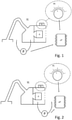
- Fig. 1 illustrates an embodiment of a vacuum cleaner VC in which a pressure difference P is measured between on the one hand, a chamber upstream of an aggregate A, and on the other hand, ambient.
- a microprocessor ⁇ P action is taken if abs[P] > P threshold , in which the threshold value P threshold depends on the power setting PS as controlled by a power setting PS control.
- This power setting control may be a rotary knob or may take any other suitable form (e.g. 3 pushbuttons for a low, a medium and a high power setting PS, or a linear touch sensor for inputting the desired power setting PS).
- microprocessor ⁇ P ensures that action is taken if abs[P] > P threshold , in which the threshold value P threshold depends on the rotation speed N of the aggregate.
- Fig. 2 illustrates an embodiment of vacuum cleaner VC in which pressure difference P is measured between on the one hand, a chamber downstream of an aggregate A, and on the other hand, ambient. Controlled by microprocessor ⁇ P, action is taken if abs[P] ⁇ P threshold , in which the threshold value P threshold depends on the power setting PS as controlled by a power setting PS control.
- microprocessor ⁇ P ensures that action is taken if abs[P] ⁇ P threshold , in which the threshold value P threshold depends on the rotation speed N of the aggregate.
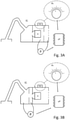
- Figs. 3A and 3B illustrate embodiments of vacuum cleaner VC in which pressure difference P is measured over a known component.
- the known component may be a flow resistance, e.g. a compartment boundary having a hole with a known size.
- the known component may be downstream of the aggregate A (as shown in Fig. 3A ), or upstream of the aggregate A (as shown in Fig. 3B ).
- microprocessor ⁇ P ensures that action is taken if abs[P] ⁇ P threshold , in which the threshold value P threshold depends on the rotation speed N of the aggregate.
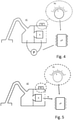
- Fig. 4 illustrates an embodiment of vacuum cleaner VC in which pressure difference P is measured over the aggregate A. Controlled by microprocessor ⁇ P, action is taken if abs[P] > P threshold , in which the threshold value P threshold depends on the power setting PS as controlled by a power setting PS control.
- microprocessor ⁇ P ensures that action is taken if abs[P] > P threshold , in which the threshold value P threshold depends on the rotation speed N of the aggregate.
- Fig. 5 illustrates an embodiment of vacuum cleaner VC in which, controlled by microprocessor ⁇ P, action is taken if N > N threshold , in which the threshold value N threshold depends on the power setting PS as controlled by the power setting PS control.
- the rotation speed N of aggregate A may be measured separately, or measured indirectly using the current through the motor, or by carrying out signal recognition on voltage peaks at a collector of the motor, or in any other suitable way.
- the above data power setting / rotation speed in combination with pressure difference between a chamber upstream/downstream of the aggregate and ambient, over a known component, or over the aggregate, or the combination of power setting and rotation speed
- microprocessor ⁇ P can be processed in microprocessor ⁇ P in order to determine the flow rate Q (using the relation between the rotation speed S and the flow rate Q of the aggregate A corresponding to the imposed power setting PS).
- Fig. 6 illustrates an embodiment of vacuum cleaner VC having an electronically controlled valve ECV that is controlled by microprocessor ⁇ P, which microprocessor ⁇ P alternatively or additionally controls aggregate A to shut it down or at least lower its rotation speed.
- the processor ⁇ P for protecting the motor-fan aggregate A from overheating and/or entering a stall regime may very well carry out other functions as well.
- the processor ⁇ P does not need to be a microprocessor; it may be any suitable control unit.
- any reference signs placed between parentheses shall not be construed as limiting the claim.
- the word "comprising” does not exclude the presence of elements or steps other than those listed in a claim.
- the word "a” or "an” preceding an element does not exclude the presence of a plurality of such elements.
- the invention may be implemented by means of hardware comprising several distinct elements, and/or by means of a suitably programmed processor.
- the device claim enumerating several means several of these means may be embodied by one and the same item of hardware.
- the mere fact that certain measures are recited in mutually different dependent claims does not indicate that a combination of these measures cannot be used to advantage.
Landscapes
- Engineering & Computer Science (AREA)
- Mechanical Engineering (AREA)
- Electric Vacuum Cleaner (AREA)
- Control Of Electric Motors In General (AREA)
- Electric Suction Cleaners (AREA)
Description
- The invention relates to a vacuum cleaner.
- Vacuum cleaners comprise an aggregate formed by a fan and a motor for driving the fan. Generally, vacuum cleaner aggregates need cooling flow to prevent the aggregate from overheating. Usually the air flow which is generated by the aggregate itself is used as cooling flow. This means that the aggregate always needs a certain amount of air flow and thus the inlet cannot be blocked completely. In case the inlet of a vacuum cleaner is blocked, the aggregate would overheat and may break down. This problem is usually solved by means of a safety valve, which opens when a specific pressure is reached. Because of the blockage of the inlet, the aggregate will generate pressure. If the pressure is sufficient high (and thus the flow rate sufficient low), the safety valve will open and provide the aggregate with the required amount of cooling flow.
-
US 6,349,738 discloses a bleed valve for introducing bled fluid to a mainstream fluid flowing through apparatus across which a pressure differential occurs. The bleed valve is adapted to open so as to bleed fluid into the mainstream fluid when the pressure differential across the apparatus falls below a predetermined value. -
US 2011/0265285 discloses a vacuum cleaner capable of detecting blockage along an airpath of vacuum by determining the amperage flow of the electrical current, and detecting blockage along an airpath by sampling the amperage flow of the electrical current and counting how many times the sampled amperage draw exceeds a threshold amperage within a window of time. When the samples sampled exceeds the percent threshold determined, power to motor assembly is terminated. -
EP 2,617,340 discloses a device that detects a pressure difference between a suction air pressure upstream of a dust collecting container and another suction air pressure downstream of the dust collecting container, and adjusts the electrical power consumption of a vacuum cleaner motor, when the detected pressure difference is above or below a preset differential pressure threshold value. - In prior art vacuum cleaners, such a bleed valve is dimensioned for the maximum suction power setting. For lower suction power settings, the bleed valve does not provide sufficient protection on its own, but this is of no big concerns as prior art vacuum cleaners allow for sufficient leakage elsewhere so that the motor is not too easily overheated. However, modern energy-conscious vacuum cleaners do not have a leakage that is sufficient to protect the motor, so that a new solution is needed to protect a vacuum cleaner motor from overheating when the suction power setting is not maximal. It is not a suitable solution to simply dimension the safety valve for a power setting lower than the maximum power setting, as this would result in the safety valve opening for power settings higher than that lower power setting for which the safety valve has been dimensioned.
- It is, inter alia, an object of the invention to provide an improved vacuum cleaner. The invention is defined by the independent claims. Advantageous embodiments are defined in the dependent claims.
- In accordance with an aspect of the invention, a vacuum cleaner comprises a motor-fan aggregate, and a control for controlling a power setting of the motor-fan aggregate, a processor is arranged for protecting the motor-fan aggregate from overheating and/or entering a stall regime in dependence on a comparison of a parameter relating to an air flow rate with a threshold that is representative of the rotation speed of the aggregate. The threshold depends on a power setting of the motor-fan aggregate. The parameter relating to the air flow rate may be a pressure difference between on the one hand a position upstream or downstream of the motor-fan aggregate, and on the other hand, ambient, a pressure difference over a known component, a pressure difference over the motor-fan aggregate, and/or - if the threshold depends on the power setting - a rotation speed of the motor-fan aggregate. The processor may be arranged for protecting the motor-fan aggregate by opening a valve upstream of the motor-fan aggregate, and/or by lowering a rotation speed of the motor-fan aggregate.
- These and other aspects of the invention will be apparent from and elucidated with reference to the embodiments described hereinafter.
-
-
Fig. 1 illustrates an embodiment of a vacuum cleaner VC in which a pressure difference P is measured between on the one hand, a chamber upstream of an aggregate A, and on the other hand, ambient; -
Fig. 2 illustrates an embodiment of vacuum cleaner VC in which pressure difference P is measured between on the one hand, a chamber downstream of aggregate A, and on the other hand, ambient; -
Figs. 3A and 3B illustrate embodiments of a vacuum cleaner VC in which pressure difference P is measured over a known component; -
Fig. 4 illustrates an embodiment of vacuum cleaner VC in which pressure difference P is measured over aggregate A; -
Fig. 5 illustrates an embodiment of vacuum cleaner VC in which, controlled by microprocessor µP, action is taken if a rotation speed N of aggregate A exceeds a threshold value Nthreshold depending on a power setting PS; -
Fig. 6 illustrates an embodiment of vacuum cleaner VC having an electronically controlled valve ECV that is controlled by microprocessor µP, which alternatively or additionally controls aggregate A to shut it down or at least lower its rotation speed; -
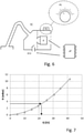
Fig. 7 illustrates a relation between pressure drop H (in mBar) and flow rate Q (in 1/s) through a component; -
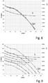
Fig. 8 illustrates aggregate performance by a relation at constant voltage between rotation speed S (in rpm) and the flow rate Q through an aggregate for one power setting for four different aggregates of a same type; and -
Fig. 9 illustrates a motor-fan performance by a relation at constant voltage between the pressure H - flow rate Q (curves with small balls ●), and the rotation speed S - flow rate Q (curves with small triangles A) through the aggregate, for five different power settings of the same aggregate. - Apart from the above-mentioned overheating problem, at low air flow rates and high pressures the aggregate can enter a stall regime. In that regime stall occurs on the fan blades, reducing the performance of the fan. The stall effect also produces a very distinguishing sound (helicopter like). Consumers can experience that as being bad for the vacuum cleaner, and dislike the use of it. The safety valve can be designed such that the aggregate will never enter the stall regime.
- In an embodiment of the invention, the flow rate is determined with a known relation, coupled to the power setting, and for each power setting a threshold flow rate is determined in order to prevent the aggregate from overheating or entering the stall regime.
- It is alternatively possible to use the rotation speed of the aggregate directly, instead of using the power setting as an input that is representative of the rotation speed. Doing so may have advantages if the mains voltage fluctuates, as in such cases the relation between power setting and rotation speed also fluctuates. This embodiment of the invention creates a safety valve by measuring the speed of rotation of the aggregate (to determine the performance of the fan) and simultaneously measuring the pressure over, or the flow-rate through, the fan. Every speed of rotation will then have its threshold, on pressure difference or flowrate, at which action should be undertaken in order to prevent overheating of the aggregate or to prevent the aggregate to entering the stall regime.
- The flow rate can be determined in different ways using:
- 1. a pressure difference between the chamber upstream or downstream of the aggregate and ambient pressure (as currently designed safety valves), or
- 2. a pressure difference over a component where the relation between pressure and flow is known and does not change in time, or
- 3. a pressure difference over the aggregate, or
- 4. a rotation speed of the aggregate. Only this last option is not possible if the rotation speed is used directly instead of the power setting, in combination with any of the above 3 pressure differences.
- The same pressure difference where the currently designed safety valves work on (chamber upstream aggregate - ambient) can be used in combination with the QH-curve (flow rate Q - pressure H relation) of the aggregate in order to determine the flow rate. For every power setting the required cooling flow is different (a lower power setting requires a lower cooling flow). Next to that, for every power setting there exists a different relation between pressure H and flow rate Q of the aggregate (see
Fig. 9 ). This means that for every power setting a different relation between pressure H and flow rate Q is used to determine whether enough cooling flow is passing through the aggregate. -
Fig. 1 illustrates an embodiment of a vacuum cleaner VC in which a pressure difference P is measured between on the one hand, a chamber upstream of an aggregate A, and on the other hand, ambient. Controlled by a microprocessor µP, action is taken if abs[P] > Pthreshold, in which the threshold value Pthreshold depends on the power setting PS as controlled by a power setting PS control. This power setting control may be a rotary knob or may take any other suitable form (e.g. 3 pushbuttons for a low, a medium and a high power setting PS, or a linear touch sensor for inputting the desired power setting PS). - Alternatively, if the rotation speed N of the aggregate A is used directly, microprocessor µP ensures that action is taken if abs[P] > Pthreshold, in which the threshold value Pthreshold depends on the rotation speed N of the aggregate.
-
Fig. 2 illustrates an embodiment of vacuum cleaner VC in which pressure difference P is measured between on the one hand, a chamber downstream of an aggregate A, and on the other hand, ambient.
Controlled by microprocessor µP, action is taken if abs[P] < Pthreshold, in which the threshold value Pthreshold depends on the power setting PS as controlled by a power setting PS control. - Alternatively, if the rotation speed N of the aggregate A is used directly, microprocessor µP ensures that action is taken if abs[P] < Pthreshold, in which the threshold value Pthreshold depends on the rotation speed N of the aggregate.
- There exists a clear relation between the pressure loss H over a component and the flow rate Q through that component (see
Fig. 7 ). By measuring the pressure difference over this component the flow rate is known. For this, the power setting PS is not necessary. However, the power setting PS has to be known to determine the threshold value of the flow rate (i.e. a lower power setting requires a lower cooling flow). -
Figs. 3A and 3B illustrate embodiments of vacuum cleaner VC in which pressure difference P is measured over a known component. The known component may be a flow resistance, e.g. a compartment boundary having a hole with a known size. The known component may be downstream of the aggregate A (as shown inFig. 3A ), or upstream of the aggregate A (as shown inFig. 3B ). - Controlled by microprocessor µP, action is taken if abs[P] < Pthreshold, in which the threshold value Pthreshold depends on the power setting PS as controlled by a power setting PS control.
- Alternatively, if the rotation speed N of the aggregate A is used directly, microprocessor µP ensures that action is taken if abs[P] < Pthreshold, in which the threshold value Pthreshold depends on the rotation speed N of the aggregate.
- There exists a clear relation between flow rate and pressure of the aggregate in a specific setting (see
Fig. 9 ). If the pressure H over the aggregate A and the power setting PS (and thus the QH-curve of the aggregate A) are known, the flow rate Q can be determined. For every power setting PS the required cooling flow is different (as a lower power setting PS requires a lower cooling flow). Next to that, for every power setting PS there exists a different relation between pressure H and flow rate Q of the aggregate (seeFig. 9 ). This means that for every power setting PS a different relation between pressure H and flow rate Q is used to determine whether enough cooling flow is passing through the aggregate A. -
Fig. 4 illustrates an embodiment of vacuum cleaner VC in which pressure difference P is measured over the aggregate A. Controlled by microprocessor µP, action is taken if abs[P] > Pthreshold, in which the threshold value Pthreshold depends on the power setting PS as controlled by a power setting PS control. - Alternatively, if the rotation speed N of the aggregate A is used directly, microprocessor µP ensures that action is taken if abs[P] > Pthreshold, in which the threshold value Pthreshold depends on the rotation speed N of the aggregate.
- There exists a clear relation between flow through the aggregate (at a specific power setting or voltage) and the rotation speed S (see
Fig. 7 ). At a specific power setting the rotation speed S will increase if the pressure H is increased, and therewith the flow rate Q decreases. By determining the rotation speed S of the aggregate, the flow rate Q through the aggregate is known. For every power setting PS the required cooling flow is different (a lower power setting PS requires a lower cooling flow). Next to that, for every power setting PS there exists a different relation between rotation speed S and flow rate Q (seeFig. 8 ). This means that for every power setting PS a different relation between rotation speed S and flow rate Q is used to determine whether enough cooling flow is passing through the aggregate A. -
Fig. 5 illustrates an embodiment of vacuum cleaner VC in which, controlled by microprocessor µP, action is taken if N > Nthreshold, in which the threshold value Nthreshold depends on the power setting PS as controlled by the power setting PS control. The rotation speed N of aggregate A may be measured separately, or measured indirectly using the current through the motor, or by carrying out signal recognition on voltage peaks at a collector of the motor, or in any other suitable way. - If it is determined that the cooling flow is too low, actions can be taken in order to prevent the aggregate A from overheating or entering the stall regime. The above data (power setting / rotation speed in combination with pressure difference between a chamber upstream/downstream of the aggregate and ambient, over a known component, or over the aggregate, or the combination of power setting and rotation speed) can be processed in microprocessor µP in order to determine the flow rate Q (using the relation between the rotation speed S and the flow rate Q of the aggregate A corresponding to the imposed power setting PS).
- After calculation of the flow rate Q, different actions can be performed if a too low flow rate is encountered:
- (electronically) open a valve upstream of the aggregate A,
- lower the rotation speed of the aggregate. The rotation speed can/will increase again to the value corresponding to the imposed power setting, if the blockage is removed. This option is possible because at a lower rotation speed a lower cooling flow is needed. Of course, lowering the rotation speed to zero (i.e. shutting down the aggregate A) is one way of lowering the speed that is very effective in protecting the aggregate from overheating.
-
Fig. 6 illustrates an embodiment of vacuum cleaner VC having an electronically controlled valve ECV that is controlled by microprocessor µP, which microprocessor µP alternatively or additionally controls aggregate A to shut it down or at least lower its rotation speed. - It should be noted that the above-mentioned embodiments illustrate rather than limit the invention, and that those skilled in the art will be able to design many alternative embodiments without departing from the scope of the appended claims. The processor µP for protecting the motor-fan aggregate A from overheating and/or entering a stall regime may very well carry out other functions as well. The processor µP does not need to be a microprocessor; it may be any suitable control unit. In the claims, any reference signs placed between parentheses shall not be construed as limiting the claim. The word "comprising" does not exclude the presence of elements or steps other than those listed in a claim. The word "a" or "an" preceding an element does not exclude the presence of a plurality of such elements. The invention may be implemented by means of hardware comprising several distinct elements, and/or by means of a suitably programmed processor. In the device claim enumerating several means, several of these means may be embodied by one and the same item of hardware. The mere fact that certain measures are recited in mutually different dependent claims does not indicate that a combination of these measures cannot be used to advantage.
Claims (3)
- A vacuum cleaner (VC) comprising:a motor-fan aggregate (A),a control for controlling a power setting (PS) of the motor-fan aggregate (A); and
a processor (µP) for protecting the motor-fan aggregate (A) from overheatingand/or entering a stall regime both being in dependence on a comparison of a parameter relating to an air flow rate with a threshold that is representative of a rotation speed of the motor-fan aggregate (A),wherein the threshold depends on a power setting (PS) of the motor-fan aggregate (A). - A vacuum cleaner as claimed in claim 1, wherein at least one of the following parameters relating to the air flow rate is used:a pressure difference between on the one hand, a position upstream or downstream of the motor-fan aggregate (A), and on the other hand, ambient, and/ora pressure difference over a known component, and/ora pressure difference over the motor-fan aggregate (A), and/ora rotation speed of the motor-fan aggregate (A).
- A vacuum cleaner as claimed in any of the preceding claims, wherein the processor (µP) is arranged for protecting the motor-fan aggregate (A) by opening a valve (ECV) upstream of the motor-fan aggregate (A), and/or by lowering a rotation speed of the
motor-fan aggregate (A).
Priority Applications (1)
| Application Number | Priority Date | Filing Date | Title |
|---|---|---|---|
| PL17720154.8T PL3316756T5 (en) | 2016-05-03 | 2017-05-03 | Vacuum cleaner |
Applications Claiming Priority (2)
| Application Number | Priority Date | Filing Date | Title |
|---|---|---|---|
| EP16168147.3A EP3241476A1 (en) | 2016-05-03 | 2016-05-03 | Vacuum cleaner |
| PCT/EP2017/060467 WO2017191155A1 (en) | 2016-05-03 | 2017-05-03 | Vacuum cleaner |
Publications (3)
| Publication Number | Publication Date |
|---|---|
| EP3316756A1 EP3316756A1 (en) | 2018-05-09 |
| EP3316756B1 EP3316756B1 (en) | 2019-01-02 |
| EP3316756B2 true EP3316756B2 (en) | 2022-03-02 |
Family
ID=55910845
Family Applications (2)
| Application Number | Title | Priority Date | Filing Date |
|---|---|---|---|
| EP16168147.3A Withdrawn EP3241476A1 (en) | 2016-05-03 | 2016-05-03 | Vacuum cleaner |
| EP17720154.8A Active EP3316756B2 (en) | 2016-05-03 | 2017-05-03 | Vacuum cleaner |
Family Applications Before (1)
| Application Number | Title | Priority Date | Filing Date |
|---|---|---|---|
| EP16168147.3A Withdrawn EP3241476A1 (en) | 2016-05-03 | 2016-05-03 | Vacuum cleaner |
Country Status (9)
| Country | Link |
|---|---|
| US (1) | US20190110655A1 (en) |
| EP (2) | EP3241476A1 (en) |
| CN (1) | CN108289585A (en) |
| DE (1) | DE202017007441U1 (en) |
| PL (1) | PL3316756T5 (en) |
| RU (1) | RU2664227C1 (en) |
| TR (1) | TR201903213T4 (en) |
| UA (1) | UA125251C2 (en) |
| WO (1) | WO2017191155A1 (en) |
Families Citing this family (5)
| Publication number | Priority date | Publication date | Assignee | Title |
|---|---|---|---|---|
| CN110870717B (en) * | 2018-08-30 | 2021-08-03 | 盛思锐股份公司 | Vacuum cleaner apparatus |
| US11259676B2 (en) | 2018-08-30 | 2022-03-01 | Sensirion Ag | Vacuum cleaner device |
| EP4137025A1 (en) * | 2021-08-19 | 2023-02-22 | Vorwerk & Co. Interholding GmbH | Method for operating a base station for a cleaning device |
| GB2622364A (en) * | 2022-09-13 | 2024-03-20 | Dyson Technology Ltd | A power control method for a motor of an air-moving device |
| GB2622366A (en) * | 2022-09-13 | 2024-03-20 | Dyson Technology Ltd | A method of determining a value of a filter loading of a filter of an air-moving device |
Citations (3)
| Publication number | Priority date | Publication date | Assignee | Title |
|---|---|---|---|---|
| DE2032476A1 (en) † | 1970-07-01 | 1972-01-05 | Licentia Gmbh | Vacuum cleaner whose compressor speed automatically adapts to the various work processes |
| EP0527567A2 (en) † | 1991-08-01 | 1993-02-17 | Hitachi, Ltd. | A method of controlling a controlled object, and a control system for such a method |
| GB2479985A (en) † | 2010-04-30 | 2011-11-02 | Oreck Holdings Llc | An arrangement to reduce noise in a vacuum cleaner |
Family Cites Families (8)
| Publication number | Priority date | Publication date | Assignee | Title |
|---|---|---|---|---|
| FR2708188A1 (en) * | 1993-07-28 | 1995-02-03 | Philips Laboratoire Electroniq | Vacuum cleaner with means of soil detection and adjustment of the engine power according to the detected soil. |
| GB2315231A (en) | 1996-07-15 | 1998-01-28 | Notetry Ltd | Apparatus for Separating Particles |
| EP0933058A1 (en) * | 1998-01-30 | 1999-08-04 | STMicroelectronics S.r.l. | Intelligent suction device capable of automatically adapting the suction force according to the conditions of the surface, particularly for vacuum cleaners and the like |
| US6777844B2 (en) * | 2000-10-24 | 2004-08-17 | Rexair, Inc. | Brushless motor |
| JP2006136512A (en) * | 2004-11-12 | 2006-06-01 | Matsushita Electric Ind Co Ltd | Electric vacuum cleaner |
| KR100676320B1 (en) * | 2005-05-30 | 2007-01-30 | 삼성광주전자 주식회사 | Apparatus for protecting motor of vaccum cleaner |
| DE102012200765A1 (en) * | 2012-01-19 | 2013-07-25 | BSH Bosch und Siemens Hausgeräte GmbH | Device and method for influencing an electrical power consumption of a vacuum cleaner motor |
| CN104521135B (en) * | 2012-09-13 | 2017-06-23 | 松下知识产权经营株式会社 | Control device of electric motor and method of motor control |
-
2016
- 2016-05-03 EP EP16168147.3A patent/EP3241476A1/en not_active Withdrawn
-
2017
- 2017-05-03 DE DE202017007441.9U patent/DE202017007441U1/en active Active
- 2017-05-03 TR TR2019/03213T patent/TR201903213T4/en unknown
- 2017-05-03 RU RU2018111445A patent/RU2664227C1/en active
- 2017-05-03 WO PCT/EP2017/060467 patent/WO2017191155A1/en active Application Filing
- 2017-05-03 UA UAA201808285A patent/UA125251C2/en unknown
- 2017-05-03 EP EP17720154.8A patent/EP3316756B2/en active Active
- 2017-05-03 US US15/751,725 patent/US20190110655A1/en not_active Abandoned
- 2017-05-03 PL PL17720154.8T patent/PL3316756T5/en unknown
- 2017-05-03 CN CN201780002891.6A patent/CN108289585A/en active Pending
Patent Citations (3)
| Publication number | Priority date | Publication date | Assignee | Title |
|---|---|---|---|---|
| DE2032476A1 (en) † | 1970-07-01 | 1972-01-05 | Licentia Gmbh | Vacuum cleaner whose compressor speed automatically adapts to the various work processes |
| EP0527567A2 (en) † | 1991-08-01 | 1993-02-17 | Hitachi, Ltd. | A method of controlling a controlled object, and a control system for such a method |
| GB2479985A (en) † | 2010-04-30 | 2011-11-02 | Oreck Holdings Llc | An arrangement to reduce noise in a vacuum cleaner |
Also Published As
| Publication number | Publication date |
|---|---|
| EP3241476A1 (en) | 2017-11-08 |
| PL3316756T3 (en) | 2019-06-28 |
| CN108289585A (en) | 2018-07-17 |
| EP3316756B1 (en) | 2019-01-02 |
| WO2017191155A1 (en) | 2017-11-09 |
| PL3316756T5 (en) | 2022-07-25 |
| US20190110655A1 (en) | 2019-04-18 |
| EP3316756A1 (en) | 2018-05-09 |
| DE202017007441U1 (en) | 2021-08-04 |
| RU2664227C1 (en) | 2018-08-15 |
| TR201903213T4 (en) | 2019-03-21 |
| UA125251C2 (en) | 2022-02-09 |
Similar Documents
| Publication | Publication Date | Title |
|---|---|---|
| EP3316756B2 (en) | Vacuum cleaner | |
| EP3073883B1 (en) | Air filter monitoring | |
| US8346507B2 (en) | System and method for detecting fluid delivery system conditions based on motor parameters | |
| EP3045733A1 (en) | Motorised impeller assemblies | |
| KR910007481A (en) | Vacuum cleaner | |
| US20140314543A1 (en) | Compressor system and method of controlling the same | |
| KR101844096B1 (en) | Method for controlling a regulated-rotation-speed low-pressure centrifugal fan | |
| US20140109653A1 (en) | Intelligent pipeline pressure sensing device | |
| JP2004159960A (en) | Electric cleaner | |
| JP4952465B2 (en) | Pipe diffuser centrifugal compressor | |
| JP2018196675A (en) | Vacuum cleaner | |
| JP2018196675A5 (en) | ||
| CN213808154U (en) | Fan device and air condensing units | |
| JP6566844B2 (en) | Range food | |
| JP2014055681A (en) | Air cleaner | |
| KR100445650B1 (en) | checking method of pipe for vacuum cleaner | |
| JP2004177063A (en) | Air conditioner | |
| JP6566845B2 (en) | Range food | |
| JP4722075B2 (en) | Air conditioner | |
| US20230272799A1 (en) | Method and fan system for determination of a current operating point of a fan unit | |
| JP7050571B2 (en) | Centrifugal fan | |
| JP3606637B2 (en) | Fluid machinery with variable guide vanes | |
| JP2005328876A (en) | Vacuum cleaner | |
| JP2003097494A (en) | Fluid machine with variable guide vane | |
| KR20050012562A (en) | Control method for prevention mechanical impact of blast furnace blower |
Legal Events
| Date | Code | Title | Description |
|---|---|---|---|
| STAA | Information on the status of an ep patent application or granted ep patent |
Free format text: STATUS: UNKNOWN |
|
| STAA | Information on the status of an ep patent application or granted ep patent |
Free format text: STATUS: THE INTERNATIONAL PUBLICATION HAS BEEN MADE |
|
| PUAI | Public reference made under article 153(3) epc to a published international application that has entered the european phase |
Free format text: ORIGINAL CODE: 0009012 |
|
| STAA | Information on the status of an ep patent application or granted ep patent |
Free format text: STATUS: REQUEST FOR EXAMINATION WAS MADE |
|
| 17P | Request for examination filed |
Effective date: 20180202 |
|
| AK | Designated contracting states |
Kind code of ref document: A1 Designated state(s): AL AT BE BG CH CY CZ DE DK EE ES FI FR GB GR HR HU IE IS IT LI LT LU LV MC MK MT NL NO PL PT RO RS SE SI SK SM TR |
|
| AX | Request for extension of the european patent |
Extension state: BA ME |
|
| GRAP | Despatch of communication of intention to grant a patent |
Free format text: ORIGINAL CODE: EPIDOSNIGR1 |
|
| STAA | Information on the status of an ep patent application or granted ep patent |
Free format text: STATUS: GRANT OF PATENT IS INTENDED |
|
| INTG | Intention to grant announced |
Effective date: 20180719 |
|
| GRAS | Grant fee paid |
Free format text: ORIGINAL CODE: EPIDOSNIGR3 |
|
| GRAA | (expected) grant |
Free format text: ORIGINAL CODE: 0009210 |
|
| STAA | Information on the status of an ep patent application or granted ep patent |
Free format text: STATUS: THE PATENT HAS BEEN GRANTED |
|
| DAV | Request for validation of the european patent (deleted) | ||
| DAX | Request for extension of the european patent (deleted) | ||
| AK | Designated contracting states |
Kind code of ref document: B1 Designated state(s): AL AT BE BG CH CY CZ DE DK EE ES FI FR GB GR HR HU IE IS IT LI LT LU LV MC MK MT NL NO PL PT RO RS SE SI SK SM TR |
|
| REG | Reference to a national code |
Ref country code: GB Ref legal event code: FG4D |
|
| REG | Reference to a national code |
Ref country code: CH Ref legal event code: EP Ref country code: AT Ref legal event code: REF Ref document number: 1083362 Country of ref document: AT Kind code of ref document: T Effective date: 20190115 |
|
| REG | Reference to a national code |
Ref country code: IE Ref legal event code: FG4D |
|
| REG | Reference to a national code |
Ref country code: DE Ref legal event code: R096 Ref document number: 602017001710 Country of ref document: DE |
|
| REG | Reference to a national code |
Ref country code: NL Ref legal event code: FP |
|
| REG | Reference to a national code |
Ref country code: LT Ref legal event code: MG4D |
|
| REG | Reference to a national code |
Ref country code: AT Ref legal event code: MK05 Ref document number: 1083362 Country of ref document: AT Kind code of ref document: T Effective date: 20190102 |
|
| PG25 | Lapsed in a contracting state [announced via postgrant information from national office to epo] |
Ref country code: NO Free format text: LAPSE BECAUSE OF FAILURE TO SUBMIT A TRANSLATION OF THE DESCRIPTION OR TO PAY THE FEE WITHIN THE PRESCRIBED TIME-LIMIT Effective date: 20190402 Ref country code: FI Free format text: LAPSE BECAUSE OF FAILURE TO SUBMIT A TRANSLATION OF THE DESCRIPTION OR TO PAY THE FEE WITHIN THE PRESCRIBED TIME-LIMIT Effective date: 20190102 Ref country code: PT Free format text: LAPSE BECAUSE OF FAILURE TO SUBMIT A TRANSLATION OF THE DESCRIPTION OR TO PAY THE FEE WITHIN THE PRESCRIBED TIME-LIMIT Effective date: 20190502 Ref country code: ES Free format text: LAPSE BECAUSE OF FAILURE TO SUBMIT A TRANSLATION OF THE DESCRIPTION OR TO PAY THE FEE WITHIN THE PRESCRIBED TIME-LIMIT Effective date: 20190102 Ref country code: LT Free format text: LAPSE BECAUSE OF FAILURE TO SUBMIT A TRANSLATION OF THE DESCRIPTION OR TO PAY THE FEE WITHIN THE PRESCRIBED TIME-LIMIT Effective date: 20190102 Ref country code: SE Free format text: LAPSE BECAUSE OF FAILURE TO SUBMIT A TRANSLATION OF THE DESCRIPTION OR TO PAY THE FEE WITHIN THE PRESCRIBED TIME-LIMIT Effective date: 20190102 |
|
| PG25 | Lapsed in a contracting state [announced via postgrant information from national office to epo] |
Ref country code: RS Free format text: LAPSE BECAUSE OF FAILURE TO SUBMIT A TRANSLATION OF THE DESCRIPTION OR TO PAY THE FEE WITHIN THE PRESCRIBED TIME-LIMIT Effective date: 20190102 Ref country code: LV Free format text: LAPSE BECAUSE OF FAILURE TO SUBMIT A TRANSLATION OF THE DESCRIPTION OR TO PAY THE FEE WITHIN THE PRESCRIBED TIME-LIMIT Effective date: 20190102 Ref country code: BG Free format text: LAPSE BECAUSE OF FAILURE TO SUBMIT A TRANSLATION OF THE DESCRIPTION OR TO PAY THE FEE WITHIN THE PRESCRIBED TIME-LIMIT Effective date: 20190402 Ref country code: IS Free format text: LAPSE BECAUSE OF FAILURE TO SUBMIT A TRANSLATION OF THE DESCRIPTION OR TO PAY THE FEE WITHIN THE PRESCRIBED TIME-LIMIT Effective date: 20190502 Ref country code: GR Free format text: LAPSE BECAUSE OF FAILURE TO SUBMIT A TRANSLATION OF THE DESCRIPTION OR TO PAY THE FEE WITHIN THE PRESCRIBED TIME-LIMIT Effective date: 20190403 Ref country code: HR Free format text: LAPSE BECAUSE OF FAILURE TO SUBMIT A TRANSLATION OF THE DESCRIPTION OR TO PAY THE FEE WITHIN THE PRESCRIBED TIME-LIMIT Effective date: 20190102 |
|
| REG | Reference to a national code |
Ref country code: DE Ref legal event code: R026 Ref document number: 602017001710 Country of ref document: DE |
|
| PLBI | Opposition filed |
Free format text: ORIGINAL CODE: 0009260 |
|
| PLAX | Notice of opposition and request to file observation + time limit sent |
Free format text: ORIGINAL CODE: EPIDOSNOBS2 |
|
| PG25 | Lapsed in a contracting state [announced via postgrant information from national office to epo] |
Ref country code: AL Free format text: LAPSE BECAUSE OF FAILURE TO SUBMIT A TRANSLATION OF THE DESCRIPTION OR TO PAY THE FEE WITHIN THE PRESCRIBED TIME-LIMIT Effective date: 20190102 Ref country code: CZ Free format text: LAPSE BECAUSE OF FAILURE TO SUBMIT A TRANSLATION OF THE DESCRIPTION OR TO PAY THE FEE WITHIN THE PRESCRIBED TIME-LIMIT Effective date: 20190102 Ref country code: SK Free format text: LAPSE BECAUSE OF FAILURE TO SUBMIT A TRANSLATION OF THE DESCRIPTION OR TO PAY THE FEE WITHIN THE PRESCRIBED TIME-LIMIT Effective date: 20190102 Ref country code: IT Free format text: LAPSE BECAUSE OF FAILURE TO SUBMIT A TRANSLATION OF THE DESCRIPTION OR TO PAY THE FEE WITHIN THE PRESCRIBED TIME-LIMIT Effective date: 20190102 Ref country code: RO Free format text: LAPSE BECAUSE OF FAILURE TO SUBMIT A TRANSLATION OF THE DESCRIPTION OR TO PAY THE FEE WITHIN THE PRESCRIBED TIME-LIMIT Effective date: 20190102 Ref country code: DK Free format text: LAPSE BECAUSE OF FAILURE TO SUBMIT A TRANSLATION OF THE DESCRIPTION OR TO PAY THE FEE WITHIN THE PRESCRIBED TIME-LIMIT Effective date: 20190102 Ref country code: EE Free format text: LAPSE BECAUSE OF FAILURE TO SUBMIT A TRANSLATION OF THE DESCRIPTION OR TO PAY THE FEE WITHIN THE PRESCRIBED TIME-LIMIT Effective date: 20190102 Ref country code: AT Free format text: LAPSE BECAUSE OF FAILURE TO SUBMIT A TRANSLATION OF THE DESCRIPTION OR TO PAY THE FEE WITHIN THE PRESCRIBED TIME-LIMIT Effective date: 20190102 |
|
| 26 | Opposition filed |
Opponent name: ALFRED KAERCHER SE & CO. KG Effective date: 20191002 |
|
| PG25 | Lapsed in a contracting state [announced via postgrant information from national office to epo] |
Ref country code: SM Free format text: LAPSE BECAUSE OF FAILURE TO SUBMIT A TRANSLATION OF THE DESCRIPTION OR TO PAY THE FEE WITHIN THE PRESCRIBED TIME-LIMIT Effective date: 20190102 |
|
| PG25 | Lapsed in a contracting state [announced via postgrant information from national office to epo] |
Ref country code: MC Free format text: LAPSE BECAUSE OF FAILURE TO SUBMIT A TRANSLATION OF THE DESCRIPTION OR TO PAY THE FEE WITHIN THE PRESCRIBED TIME-LIMIT Effective date: 20190102 |
|
| REG | Reference to a national code |
Ref country code: BE Ref legal event code: MM Effective date: 20190531 |
|
| PLBB | Reply of patent proprietor to notice(s) of opposition received |
Free format text: ORIGINAL CODE: EPIDOSNOBS3 |
|
| PG25 | Lapsed in a contracting state [announced via postgrant information from national office to epo] |
Ref country code: LU Free format text: LAPSE BECAUSE OF NON-PAYMENT OF DUE FEES Effective date: 20190503 |
|
| RAP2 | Party data changed (patent owner data changed or rights of a patent transferred) |
Owner name: KONINKLIJKE PHILIPS N.V. |
|
| PG25 | Lapsed in a contracting state [announced via postgrant information from national office to epo] |
Ref country code: IE Free format text: LAPSE BECAUSE OF NON-PAYMENT OF DUE FEES Effective date: 20190503 |
|
| PG25 | Lapsed in a contracting state [announced via postgrant information from national office to epo] |
Ref country code: BE Free format text: LAPSE BECAUSE OF NON-PAYMENT OF DUE FEES Effective date: 20190531 |
|
| PG25 | Lapsed in a contracting state [announced via postgrant information from national office to epo] |
Ref country code: CH Free format text: LAPSE BECAUSE OF NON-PAYMENT OF DUE FEES Effective date: 20200531 Ref country code: LI Free format text: LAPSE BECAUSE OF NON-PAYMENT OF DUE FEES Effective date: 20200531 |
|
| PG25 | Lapsed in a contracting state [announced via postgrant information from national office to epo] |
Ref country code: CY Free format text: LAPSE BECAUSE OF FAILURE TO SUBMIT A TRANSLATION OF THE DESCRIPTION OR TO PAY THE FEE WITHIN THE PRESCRIBED TIME-LIMIT Effective date: 20190102 |
|
| PG25 | Lapsed in a contracting state [announced via postgrant information from national office to epo] |
Ref country code: MT Free format text: LAPSE BECAUSE OF FAILURE TO SUBMIT A TRANSLATION OF THE DESCRIPTION OR TO PAY THE FEE WITHIN THE PRESCRIBED TIME-LIMIT Effective date: 20190102 Ref country code: HU Free format text: LAPSE BECAUSE OF FAILURE TO SUBMIT A TRANSLATION OF THE DESCRIPTION OR TO PAY THE FEE WITHIN THE PRESCRIBED TIME-LIMIT; INVALID AB INITIO Effective date: 20170503 |
|
| PG25 | Lapsed in a contracting state [announced via postgrant information from national office to epo] |
Ref country code: SI Free format text: LAPSE BECAUSE OF FAILURE TO SUBMIT A TRANSLATION OF THE DESCRIPTION OR TO PAY THE FEE WITHIN THE PRESCRIBED TIME-LIMIT Effective date: 20190102 |
|
| PUAH | Patent maintained in amended form |
Free format text: ORIGINAL CODE: 0009272 |
|
| STAA | Information on the status of an ep patent application or granted ep patent |
Free format text: STATUS: PATENT MAINTAINED AS AMENDED |
|
| 27A | Patent maintained in amended form |
Effective date: 20220302 |
|
| AK | Designated contracting states |
Kind code of ref document: B2 Designated state(s): AL AT BE BG CH CY CZ DE DK EE ES FI FR GB GR HR HU IE IS IT LI LT LU LV MC MK MT NL NO PL PT RO RS SE SI SK SM TR |
|
| REG | Reference to a national code |
Ref country code: DE Ref legal event code: R102 Ref document number: 602017001710 Country of ref document: DE |
|
| REG | Reference to a national code |
Ref country code: NL Ref legal event code: FP |
|
| PG25 | Lapsed in a contracting state [announced via postgrant information from national office to epo] |
Ref country code: MK Free format text: LAPSE BECAUSE OF FAILURE TO SUBMIT A TRANSLATION OF THE DESCRIPTION OR TO PAY THE FEE WITHIN THE PRESCRIBED TIME-LIMIT Effective date: 20190102 |
|
| P01 | Opt-out of the competence of the unified patent court (upc) registered |
Effective date: 20230530 |
|
| PGFP | Annual fee paid to national office [announced via postgrant information from national office to epo] |
Ref country code: NL Payment date: 20230525 Year of fee payment: 7 Ref country code: FR Payment date: 20230523 Year of fee payment: 7 Ref country code: DE Payment date: 20230530 Year of fee payment: 7 |
|
| PGFP | Annual fee paid to national office [announced via postgrant information from national office to epo] |
Ref country code: TR Payment date: 20230419 Year of fee payment: 7 Ref country code: PL Payment date: 20230421 Year of fee payment: 7 |
|
| PGFP | Annual fee paid to national office [announced via postgrant information from national office to epo] |
Ref country code: GB Payment date: 20230523 Year of fee payment: 7 |
|
| REG | Reference to a national code |
Ref country code: NL Ref legal event code: PD Owner name: VERSUNI HOLDING B.V.; NL Free format text: DETAILS ASSIGNMENT: CHANGE OF OWNER(S), ASSIGNMENT; FORMER OWNER NAME: KONINKLIJKE PHILIPS N.V. Effective date: 20231108 |
|
| REG | Reference to a national code |
Ref country code: DE Ref legal event code: R081 Ref document number: 602017001710 Country of ref document: DE Owner name: VERSUNI HOLDING B.V., NL Free format text: FORMER OWNER: KONINKLIJKE PHILIPS N.V., EINDHOVEN, NL |
|
| REG | Reference to a national code |
Ref country code: GB Ref legal event code: 732E Free format text: REGISTERED BETWEEN 20231214 AND 20231220 |