JP2018196675A - Vacuum cleaner - Google Patents
Vacuum cleaner Download PDFInfo
- Publication number
- JP2018196675A JP2018196675A JP2017103223A JP2017103223A JP2018196675A JP 2018196675 A JP2018196675 A JP 2018196675A JP 2017103223 A JP2017103223 A JP 2017103223A JP 2017103223 A JP2017103223 A JP 2017103223A JP 2018196675 A JP2018196675 A JP 2018196675A
- Authority
- JP
- Japan
- Prior art keywords
- dust
- input power
- detection sensor
- electric blower
- vacuum cleaner
- Prior art date
- Legal status (The legal status is an assumption and is not a legal conclusion. Google has not performed a legal analysis and makes no representation as to the accuracy of the status listed.)
- Pending
Links
Images


Classifications
-
- Y—GENERAL TAGGING OF NEW TECHNOLOGICAL DEVELOPMENTS; GENERAL TAGGING OF CROSS-SECTIONAL TECHNOLOGIES SPANNING OVER SEVERAL SECTIONS OF THE IPC; TECHNICAL SUBJECTS COVERED BY FORMER USPC CROSS-REFERENCE ART COLLECTIONS [XRACs] AND DIGESTS
- Y02—TECHNOLOGIES OR APPLICATIONS FOR MITIGATION OR ADAPTATION AGAINST CLIMATE CHANGE
- Y02B—CLIMATE CHANGE MITIGATION TECHNOLOGIES RELATED TO BUILDINGS, e.g. HOUSING, HOUSE APPLIANCES OR RELATED END-USER APPLICATIONS
- Y02B40/00—Technologies aiming at improving the efficiency of home appliances, e.g. induction cooking or efficient technologies for refrigerators, freezers or dish washers
Abstract
Description
本発明は、集塵室内の塵埃の量を正確に判定することができる電気掃除機に関するものである。 The present invention relates to a vacuum cleaner that can accurately determine the amount of dust in a dust collection chamber.
従来の電気掃除機として図7に示すようなものがあった。図7は、従来の電気掃除機の回路図である。 There is a conventional vacuum cleaner as shown in FIG. FIG. 7 is a circuit diagram of a conventional vacuum cleaner.
図7において、従来の電気掃除機は、電動送風機1に流れる電流を検出する電流センサ3と、集塵室(図示せず)内に堆積された塵埃の量を表示する表示手段5と、電動送風機1を駆動する駆動手段2と、塵埃を検知する塵埃検知センサ6からの信号に応じて前記電動送風機1の入力電力を制御する制御手段4とを備え、前記塵埃検知センサ6が塵埃を検知したときに、前記電動送風機1の入力電力を大きくなるように制御し、前記塵埃検知センサ6が塵埃を検知していない間に前記電流センサ3で検出された電流値に応じて、前記表示手段5を制御するようにしていた(例えば、特許文献1参照)。
In FIG. 7, the conventional vacuum cleaner includes a
しかしながら、このような従来の電気掃除機では、塵埃が溜まり、電流センサ3で検出された電流値が所定の値以下になったときに、電動送風機1の入力電力を小さくすることで、電動送風機1の温度上昇を抑制することができるが、集塵塵埃の量による電流値の変化が小さい場合、集塵室内の塵埃の量の判定が困難になるという課題があった。また、電動送風機1の回転数で塵埃の量を判定する場合も同様の課題があった。
However, in such a conventional vacuum cleaner, when the dust accumulates and the current value detected by the
本発明は、上記従来の課題を解決するもので、集塵室内の塵埃の量をより正確に判定することを目的とする。 The present invention solves the above-described conventional problems, and an object thereof is to more accurately determine the amount of dust in a dust collection chamber.
上記従来の課題を解決するため、本発明の電気掃除機は、電動送風機と集塵室を備えた掃除機本体と、前記集塵室に連通する通気路内を通過する塵埃を検知する塵埃検知センサと、前記塵埃検知センサからの信号に応じて前記電動送風機の入力電力を制御する制御手段と、前記電動送風機の回転数を検出する回転数検知センサを備え、前記塵埃検知センサが塵埃を検知したときに、前記電動送風機の入力電力を大きくなるように制御し、前記回転数検知センサで検出された回転数が所定の値以上になったときに、前記電動送風機の入力電力を小さくなるように制御するもので、判定が困難な低入力電力の運転時でも、一時的に入力電力を増加するように制御することで、回転数を上昇させ、前記回転数検知センサで検出された回転数が所定の値以上になったときに入力電力を小さくすることができる。これにより、前記電動送風機の温度上昇の抑制と集塵室内の塵埃の量を正確に判定することができる。 In order to solve the above-described conventional problems, the vacuum cleaner of the present invention includes a vacuum cleaner main body including an electric blower and a dust collection chamber, and dust detection for detecting dust passing through a ventilation passage communicating with the dust collection chamber. A sensor, a control means for controlling input power of the electric blower in accordance with a signal from the dust detection sensor, and a rotation speed detection sensor for detecting the rotation speed of the electric blower, wherein the dust detection sensor detects dust. The input power of the electric blower is controlled so as to increase, and the input power of the electric blower is reduced when the rotational speed detected by the rotational speed detection sensor becomes a predetermined value or more. Even during operation with low input power, which is difficult to determine, the rotational speed is increased by controlling to temporarily increase the input power, and the rotational speed detected by the rotational speed detection sensor. Is given It is possible to reduce the input power when it is above. Thereby, it is possible to accurately determine the suppression of the temperature rise of the electric blower and the amount of dust in the dust collection chamber.
本発明の電気掃除機は、集塵室内の塵埃の量の判定が困難な低入力電力の運転時でも集塵室内の塵埃の量を正確に判定することができる。 The vacuum cleaner of the present invention can accurately determine the amount of dust in the dust collection chamber even during operation with low input power, where it is difficult to determine the amount of dust in the dust collection chamber.
第1の発明は、電動送風機と集塵室を備えた掃除機本体と、前記集塵室に連通する通気路内を通過する塵埃を検知する塵埃検知センサと、前記塵埃検知センサからの信号に応じて前記電動送風機の入力電力を制御する制御手段と、前記電動送風機の回転数を検出する回転数検知センサを備え、前記塵埃検知センサが塵埃を検知したときに、前記電動送風機の入力電力を大きくなるように制御し、前記回転数検知センサで検出された回転数が所定の値以上になったときに、前記電動送風機の入力電力を小さくなるように制御するもので、判定が困難な低入力電力の運転時でも、一時的に入力電力を増加するように制御することで、回転数を上昇させ、前記回転数検知センサで検出された回転数が所定の値以上になったときに入力電力を小さくすることができる。これにより、前記電動送風機の温度上昇の抑制と集塵室内の塵埃の量を正確に判定することができる。 According to a first aspect of the present invention, there is provided a vacuum cleaner body including an electric blower and a dust collection chamber, a dust detection sensor for detecting dust passing through a ventilation passage communicating with the dust collection chamber, and a signal from the dust detection sensor. And a control means for controlling the input power of the electric blower, and a rotation speed detection sensor for detecting the rotation speed of the electric blower. When the dust detection sensor detects dust, the input power of the electric blower is changed. It is controlled so as to increase, and when the rotational speed detected by the rotational speed detection sensor exceeds a predetermined value, the input power of the electric blower is controlled to be small. Even during operation of input power, control is performed to increase the input power temporarily to increase the rotation speed, and input when the rotation speed detected by the rotation speed detection sensor exceeds a predetermined value. Reduce power It is possible. Thereby, it is possible to accurately determine the suppression of the temperature rise of the electric blower and the amount of dust in the dust collection chamber.
第2の発明は、特に、第1の発明の塵埃検知センサが検知する塵埃の量に応じて、塵埃の通過度合を算出し、前記通過度合いが一定の値を越えた際に、電動送風機の入力電力を大きくするように制御するもので、掃除箇所の塵埃の量に応じて入力電力が大きくなる機会が決定され、集塵室内の塵埃の量をより正確に判定することができる。 In particular, the second invention calculates the degree of passage of dust according to the amount of dust detected by the dust detection sensor of the first invention, and when the degree of passage exceeds a certain value, Since the input power is controlled to increase, an opportunity to increase the input power is determined according to the amount of dust in the cleaning location, and the amount of dust in the dust collection chamber can be determined more accurately.
第3の発明は、特に、第1又は第2の発明の電動送風機の入力電力が小さい時間が一定期間経過すると前記入力電力を大きくするように制御するもので、塵埃が塵埃検知センサを通過しない場合でも入力電力を大きくすることができ、集塵室内の塵埃の量をより正確に判定することができる。 In the third invention, in particular, when the input power of the electric blower of the first or second invention is low, the input power is controlled to increase when a certain period of time elapses, so that dust does not pass through the dust detection sensor. Even in this case, the input power can be increased, and the amount of dust in the dust collection chamber can be determined more accurately.
第4の発明は、特に、第1〜3のいずれか一つの発明の電動送風機の入力電力が大きくなる継続時間を長くするように制御するもので、電動送風機の回転数が安定した状態で集塵室内の塵埃の量をより正確に判定することができる。 The fourth aspect of the invention controls the electric blower of any one of the first to third aspects of the invention so as to increase the duration of time during which the input power increases, and the electric blower is collected in a stable state. The amount of dust in the dust chamber can be determined more accurately.
以下、本発明の実施の形態について、図面を参照しながら説明する。なお、この実施の形態によって本発明が限定されるものではない。 Hereinafter, embodiments of the present invention will be described with reference to the drawings. Note that the present invention is not limited to the embodiments.
(実施の形態1)
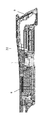
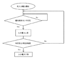
図1は、本発明の第1の実施の形態における電気掃除機の部分断面図、図2は、同電気掃除機の回路図、図3は、同電気掃除機の運転時間と電動送風機の入力電力の関係図、図4は、同電気掃除機の塵埃量判定のフローチャートである。
(Embodiment 1)
FIG. 1 is a partial sectional view of a vacuum cleaner according to a first embodiment of the present invention, FIG. 2 is a circuit diagram of the vacuum cleaner, and FIG. 3 is an operation time of the vacuum cleaner and an input of an electric blower FIG. 4 is a flowchart of the dust amount determination of the electric vacuum cleaner.
図1〜4において、本実施の形態における電気掃除機10は、電動送風機1と集塵室8を内蔵した掃除機本体9と、電動送風機1の回転を制御するための駆動手段2と、電動送風機1の回転数の値を検知するための回転数検知センサ30と、電気掃除機10の動作を制御するための制御手段4と、吸引された塵埃の量を知らせるための表示手段5と、集塵
室8に連通する通気路(図示せず)内を通過する塵埃を検知するための塵埃検知センサ6と、複数段階に分けられた電動送風機1の入力電力を使用者が任意に選択するための選択手段7とを備え、その選択手段7の内の一つに、塵埃検知センサ6の出力に応じて電動送風機1を運転する「自動ポジション」がある。
1-4, the
まず、使用者が、選択手段7により、電気掃除機10を塵埃検知センサ6の出力に応じて運転する「自動ポジション」を選択した場合、塵埃検知センサ6で塵埃が検出されていないときは、例えば、電動送風機1の入力電力が第1の所定値、例えば60W程度になるように設定されているが、一方、塵埃検知センサ6で塵埃が検出された場合は、図3に示すように、電動送風機1の入力電力を第2の所定値、例えば140W程度まで増加させるような制御を行う。
First, when the user selects “automatic position” in which the
このとき、電気掃除機10に設けられた塵埃捕集用の集塵室8内に塵埃が増えてくると、風量が小さくなると共に、集塵室8内の真空度が上がるため、電動送風機1にかかる負荷が少なくなる。それにより電動送風機1の回転数が上昇し、回転数検知センサ30によって検知される回転数の値も大きくなる。
At this time, if dust increases in the
この回転数検知センサ30によって検知された回転数の値を制御手段4に送り、回転数の値があらかじめ決定した所定の値以上になった場合、集塵室8内に塵埃が多量に溜まってきたと判断し、表示手段5でその溜まり具合を表示するように信号を制御手段4より送るようにする。またそれと同時に、電動送風機1の入力電力を小さくし、電動送風機1の加熱を防止するようにする。
When the rotational speed value detected by the rotational speed detection sensor 30 is sent to the control means 4 and the rotational speed value exceeds a predetermined value, a large amount of dust accumulates in the
なお、上記所定の値を複数設けるようにすると、集塵室8内の塵埃の増加に伴って、それを表示手段5で段階的に表示することが可能になり、一層使い勝手が向上するものである。
If a plurality of the predetermined values are provided, as the dust in the
「自動ポジション」のような低入力電力での運転では、集塵室8内に塵埃が溜まっている時と溜まっていない時との電動送風機1の回転数差が小さいため、電動送風機1の個体差によっては正確に集塵室8内の塵埃量を判定することが困難である。しかし、塵埃検知センサ6の出力に応じて入力電力を第3の所定値、例えば200W程度まで上昇させ、その間に上記判定を行うことで低入力電力での運転時でも正確に集塵室8内の塵埃の量を判定することが可能である。
In operation with low input power such as “automatic position”, the difference in the rotational speed of the
また、集塵室8内に塵埃がたまり、電動送風機1が低入力電力で運転制御されている時に、塵埃検知センサ6によって通気路中の塵埃が検知されても、電動送風機1の入力電力を上げず、一定の入力電力で制御するようにして、電動送風機1の発熱を抑える。
Further, when dust accumulates in the
なお、上記実施の形態では、塵埃検知センサ6で塵埃が検出された場合、電動送風機1の入力電力を140W程度まで増加させるような制御を行うようにしたが、図3に示すように、塵埃検知センサ6で塵埃を検知した時、電動送風機1の入力電力を200W程度まで増加させると共に、その入力を大きくしている時間を一定期間継続させるように制御すれば、電動送風機1の回転数を一定の値で安定させることができ、より正確に集塵室8内の塵埃の量を判定することができる。
In the above embodiment, when dust is detected by the
(実施の形態2)
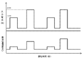
図5は、本発明の実施の形態2における電気掃除機の運転時間と、塵埃の通過度合い及び電動送風機の入力電力との関係を示す図である。なお、上記実施の形態1と同一部分については同一符号を付して説明を省略する。
(Embodiment 2)
FIG. 5 is a diagram illustrating the relationship between the operation time of the electric vacuum cleaner, the degree of dust passage, and the input power of the electric blower in
本実施の形態における電気掃除機10は、図5に示すように、塵埃検知センサ6で検知される塵埃の通過度合いが低い値では、入力電力を第2の所定値、例えば140W程度までしか増加させず、塵埃の通過度合いの値が一定以上の場合は入力電力を第3の所定値、例えば200W程度まで増加させるように制御して、塵埃を多量に吸引した際に集塵室8内の塵埃の量を判定するようにしたものである。
As shown in FIG. 5, the
これにより、通気路内での塵埃詰まりの抑制と、塵埃量に合わせた入力電力の制御が可能となるため運転時間の向上が見込まれる。 Accordingly, it is possible to suppress the clogging of dust in the air passage and to control the input power in accordance with the amount of dust, so that the operation time can be improved.
(実施の形態3)
図6は、本発明の実施の形態3における電気掃除機の運転時間経過に伴う電動送風機の入力電力の推移を示すものである。なお、上記実施の形態と同一部分については同一符号を付して説明を省略する。
(Embodiment 3)
FIG. 6 shows the transition of the input power of the electric blower as the operation time of the electric vacuum cleaner in
本実施の形態における電気掃除機10は、電動送風機1の入力電力を第3の所定値、例えば200W程度まで上昇させる制御が行われてから一定期間は、制御手段4が塵埃検知センサ6から信号を受けても、第2の所定値、例えば140W程度までしか入力電力が上昇しないようにし、一定時間が経過すると入力電力を自動的に第3の所定値、例えば200W程度まで上昇させる制御を行うようにするものである。これにより、塵埃の通過度合いが低い場合でも、集塵室8内の塵埃の量を定期的に判定することができる。
In the
以上のように上記実施の形態における電気掃除機によれば、従来の電気掃除機の集塵室8内の塵埃の量の判定方法では、実現できなかった低入力電力での運転時の集塵室8内の塵埃の量の判定を、塵埃検知センサ6が塵埃を検知したときに入力電力を増加させることにより、電動送風機1の回転数を上昇させ、集塵室8内の塵埃の量の判定をより正確に行うことが可能になるものである。
As described above, according to the vacuum cleaner in the above-described embodiment, dust collection during operation at low input power, which could not be realized by the method for determining the amount of dust in the
また、塵埃の通過度合いが低い値では入力電力を第2の所定値、例えば140W程度までしか増加させず、塵埃の通過度合いの値がある一定以上の場合は入力電力が第3の所定値、例えば200W程度まで増加させるような制御を行うことで、通気路内での塵埃詰まりの抑制と、塵埃量に合わせた入力電力の制御が可能となるため運転時間の向上が見込まれる。 Further, the input power is increased only to a second predetermined value, for example, about 140 W when the dust passage degree is low, and the input power is set to a third predetermined value when the dust passage degree is a certain value or more. For example, by performing the control to increase the power to about 200 W, it is possible to suppress the clogging of dust in the air passage and to control the input power in accordance with the amount of dust, so that the operation time can be improved.
以上のように、本発明に係る電気掃除機は、集塵室内の塵埃の量を正確に判定することができるため、長い運転時間を維持しながら集塵室内の塵埃の量を正確に判定することができるので、各種電気掃除機に適用できる。 As described above, since the vacuum cleaner according to the present invention can accurately determine the amount of dust in the dust collection chamber, it accurately determines the amount of dust in the dust collection chamber while maintaining a long operation time. It can be applied to various vacuum cleaners.
1 電動送風機
2 駆動手段
4 制御手段
5 表示手段
6 塵埃検知センサ
7 選択手段
8 集塵室
9 掃除機本体
10 電気掃除機
30 回転数検知センサ
DESCRIPTION OF
Claims (4)
Priority Applications (1)
| Application Number | Priority Date | Filing Date | Title |
|---|---|---|---|
| JP2017103223A JP2018196675A (en) | 2017-05-25 | 2017-05-25 | Vacuum cleaner |
Applications Claiming Priority (1)
| Application Number | Priority Date | Filing Date | Title |
|---|---|---|---|
| JP2017103223A JP2018196675A (en) | 2017-05-25 | 2017-05-25 | Vacuum cleaner |
Publications (2)
| Publication Number | Publication Date |
|---|---|
| JP2018196675A true JP2018196675A (en) | 2018-12-13 |
| JP2018196675A5 JP2018196675A5 (en) | 2019-11-21 |
Family
ID=64663230
Family Applications (1)
| Application Number | Title | Priority Date | Filing Date |
|---|---|---|---|
| JP2017103223A Pending JP2018196675A (en) | 2017-05-25 | 2017-05-25 | Vacuum cleaner |
Country Status (1)
| Country | Link |
|---|---|
| JP (1) | JP2018196675A (en) |
Cited By (3)
| Publication number | Priority date | Publication date | Assignee | Title |
|---|---|---|---|---|
| WO2020080462A1 (en) | 2018-10-18 | 2020-04-23 | 株式会社カーブスジャパン | Stretching exercise apparatus |
| WO2020202263A1 (en) * | 2019-03-29 | 2020-10-08 | 三菱電機株式会社 | Electric vacuum cleaner |
| JP7365795B2 (en) | 2019-06-26 | 2023-10-20 | シャープ株式会社 | vacuum cleaner |
Citations (6)
| Publication number | Priority date | Publication date | Assignee | Title |
|---|---|---|---|---|
| JPH07163499A (en) * | 1993-12-15 | 1995-06-27 | Tec Corp | Vacuum cleaner |
| JPH0824185A (en) * | 1994-07-15 | 1996-01-30 | Mitsubishi Electric Corp | Vacuum cleaner |
| JP2001087191A (en) * | 1999-09-22 | 2001-04-03 | Matsushita Electric Ind Co Ltd | Vacuum cleaner |
| JP2004057445A (en) * | 2002-07-29 | 2004-02-26 | Matsushita Electric Ind Co Ltd | Vacuum cleaner |
| JP2006320454A (en) * | 2005-05-18 | 2006-11-30 | Matsushita Electric Ind Co Ltd | Vacuum cleaner |
| US20110115638A1 (en) * | 2009-11-16 | 2011-05-19 | Industrial Technology Research Institute | Method for controlling cleaning device |
-
2017
- 2017-05-25 JP JP2017103223A patent/JP2018196675A/en active Pending
Patent Citations (6)
| Publication number | Priority date | Publication date | Assignee | Title |
|---|---|---|---|---|
| JPH07163499A (en) * | 1993-12-15 | 1995-06-27 | Tec Corp | Vacuum cleaner |
| JPH0824185A (en) * | 1994-07-15 | 1996-01-30 | Mitsubishi Electric Corp | Vacuum cleaner |
| JP2001087191A (en) * | 1999-09-22 | 2001-04-03 | Matsushita Electric Ind Co Ltd | Vacuum cleaner |
| JP2004057445A (en) * | 2002-07-29 | 2004-02-26 | Matsushita Electric Ind Co Ltd | Vacuum cleaner |
| JP2006320454A (en) * | 2005-05-18 | 2006-11-30 | Matsushita Electric Ind Co Ltd | Vacuum cleaner |
| US20110115638A1 (en) * | 2009-11-16 | 2011-05-19 | Industrial Technology Research Institute | Method for controlling cleaning device |
Cited By (4)
| Publication number | Priority date | Publication date | Assignee | Title |
|---|---|---|---|---|
| WO2020080462A1 (en) | 2018-10-18 | 2020-04-23 | 株式会社カーブスジャパン | Stretching exercise apparatus |
| WO2020202263A1 (en) * | 2019-03-29 | 2020-10-08 | 三菱電機株式会社 | Electric vacuum cleaner |
| JP7191205B2 (en) | 2019-03-29 | 2022-12-16 | 三菱電機株式会社 | vacuum cleaner |
| JP7365795B2 (en) | 2019-06-26 | 2023-10-20 | シャープ株式会社 | vacuum cleaner |
Similar Documents
| Publication | Publication Date | Title |
|---|---|---|
| JP2018196675A (en) | Vacuum cleaner | |
| US9173537B2 (en) | Vacuum cleaner and method for operating a vacuum cleaner | |
| EP2839219B1 (en) | Hood and method of operation thereof | |
| JPWO2016021214A1 (en) | Dehumidifier | |
| JP2014059116A (en) | Air cleaner | |
| JP2007130207A (en) | Vacuum cleaner | |
| JP2018196675A5 (en) | ||
| JP5771335B2 (en) | Humidifier and method for monitoring water level in humidifier | |
| KR20100003027A (en) | System and method for sensing fault of brushless direct current motor hall sensor of air cleaner | |
| JP2001136780A (en) | Control circuit for motor-driven blower and vacuum cleaner | |
| JP2001087191A (en) | Vacuum cleaner | |
| JP5219007B2 (en) | Electronic device and cooling fan control method | |
| JP2013233198A (en) | Vacuum cleaner | |
| JP2009262020A (en) | Air cleaner | |
| JP2004159960A (en) | Electric cleaner | |
| JP5003162B2 (en) | Air conditioner | |
| JP4946681B2 (en) | Electric vacuum cleaner | |
| JP2016068064A (en) | Dehumidifier | |
| JP2014055681A (en) | Air cleaner | |
| JP4380329B2 (en) | Air conditioner | |
| JP2011021787A (en) | Air cleaner | |
| JP2010190477A (en) | Operation control device for range hood | |
| JP2007054225A (en) | Vacuum cleaner | |
| JP2013053753A (en) | Air conditioner | |
| JP2009106836A (en) | Air conditioner |
Legal Events
| Date | Code | Title | Description |
|---|---|---|---|
| RD01 | Notification of change of attorney |
Free format text: JAPANESE INTERMEDIATE CODE: A7421 Effective date: 20190121 |
|
| A521 | Request for written amendment filed |
Free format text: JAPANESE INTERMEDIATE CODE: A523 Effective date: 20191010 |
|
| A621 | Written request for application examination |
Free format text: JAPANESE INTERMEDIATE CODE: A621 Effective date: 20191011 |
|
| A977 | Report on retrieval |
Free format text: JAPANESE INTERMEDIATE CODE: A971007 Effective date: 20200817 |
|
| A131 | Notification of reasons for refusal |
Free format text: JAPANESE INTERMEDIATE CODE: A131 Effective date: 20200825 |
|
| A521 | Request for written amendment filed |
Free format text: JAPANESE INTERMEDIATE CODE: A523 Effective date: 20201015 |
|
| A02 | Decision of refusal |
Free format text: JAPANESE INTERMEDIATE CODE: A02 Effective date: 20201027 |