EP3316366A1 - Positive electrode of lithium-air battery having side reaction prevention film to which metal catalyst is partially introduced, lithium-air battery having same, and manufacturing method therefor - Google Patents
Positive electrode of lithium-air battery having side reaction prevention film to which metal catalyst is partially introduced, lithium-air battery having same, and manufacturing method therefor Download PDFInfo
- Publication number
- EP3316366A1 EP3316366A1 EP17741621.1A EP17741621A EP3316366A1 EP 3316366 A1 EP3316366 A1 EP 3316366A1 EP 17741621 A EP17741621 A EP 17741621A EP 3316366 A1 EP3316366 A1 EP 3316366A1
- Authority
- EP
- European Patent Office
- Prior art keywords
- lithium
- oxide
- positive electrode
- air battery
- carbon
- Prior art date
- Legal status (The legal status is an assumption and is not a legal conclusion. Google has not performed a legal analysis and makes no representation as to the accuracy of the status listed.)
- Granted
Links
- 238000007086 side reaction Methods 0.000 title claims abstract description 48
- 229910052751 metal Inorganic materials 0.000 title claims abstract description 47
- 239000002184 metal Substances 0.000 title claims abstract description 47
- 230000002265 prevention Effects 0.000 title claims abstract description 40
- 239000003054 catalyst Substances 0.000 title claims abstract description 33
- 238000004519 manufacturing process Methods 0.000 title description 2
- 238000000034 method Methods 0.000 claims abstract description 20
- 239000003792 electrolyte Substances 0.000 claims abstract description 11
- OKTJSMMVPCPJKN-UHFFFAOYSA-N Carbon Chemical compound [C] OKTJSMMVPCPJKN-UHFFFAOYSA-N 0.000 claims description 56
- 229910052799 carbon Inorganic materials 0.000 claims description 51
- 239000004020 conductor Substances 0.000 claims description 43
- 239000011248 coating agent Substances 0.000 claims description 19
- 238000000576 coating method Methods 0.000 claims description 19
- 229910044991 metal oxide Inorganic materials 0.000 claims description 18
- 150000004706 metal oxides Chemical class 0.000 claims description 18
- 238000000151 deposition Methods 0.000 claims description 15
- -1 SZO Chemical compound 0.000 claims description 12
- 229910052744 lithium Inorganic materials 0.000 claims description 11
- 230000008021 deposition Effects 0.000 claims description 10
- WHXSMMKQMYFTQS-UHFFFAOYSA-N Lithium Chemical compound [Li] WHXSMMKQMYFTQS-UHFFFAOYSA-N 0.000 claims description 7
- 229910003437 indium oxide Inorganic materials 0.000 claims description 7
- PJXISJQVUVHSOJ-UHFFFAOYSA-N indium(iii) oxide Chemical compound [O-2].[O-2].[O-2].[In+3].[In+3] PJXISJQVUVHSOJ-UHFFFAOYSA-N 0.000 claims description 7
- XLOMVQKBTHCTTD-UHFFFAOYSA-N zinc oxide Inorganic materials [Zn]=O XLOMVQKBTHCTTD-UHFFFAOYSA-N 0.000 claims description 7
- AMGQUBHHOARCQH-UHFFFAOYSA-N indium;oxotin Chemical compound [In].[Sn]=O AMGQUBHHOARCQH-UHFFFAOYSA-N 0.000 claims description 6
- GYHNNYVSQQEPJS-UHFFFAOYSA-N Gallium Chemical compound [Ga] GYHNNYVSQQEPJS-UHFFFAOYSA-N 0.000 claims description 5
- PXHVJJICTQNCMI-UHFFFAOYSA-N Nickel Chemical compound [Ni] PXHVJJICTQNCMI-UHFFFAOYSA-N 0.000 claims description 5
- KDLHZDBZIXYQEI-UHFFFAOYSA-N Palladium Chemical compound [Pd] KDLHZDBZIXYQEI-UHFFFAOYSA-N 0.000 claims description 5
- 229910052733 gallium Inorganic materials 0.000 claims description 5
- BASFCYQUMIYNBI-UHFFFAOYSA-N platinum Chemical compound [Pt] BASFCYQUMIYNBI-UHFFFAOYSA-N 0.000 claims description 5
- YVTHLONGBIQYBO-UHFFFAOYSA-N zinc indium(3+) oxygen(2-) Chemical compound [O--].[Zn++].[In+3] YVTHLONGBIQYBO-UHFFFAOYSA-N 0.000 claims description 5
- 239000011787 zinc oxide Substances 0.000 claims description 5
- 229910045601 alloy Inorganic materials 0.000 claims description 4
- 239000000956 alloy Substances 0.000 claims description 4
- JAONJTDQXUSBGG-UHFFFAOYSA-N dialuminum;dizinc;oxygen(2-) Chemical compound [O-2].[O-2].[O-2].[O-2].[O-2].[Al+3].[Al+3].[Zn+2].[Zn+2] JAONJTDQXUSBGG-UHFFFAOYSA-N 0.000 claims description 4
- 239000002245 particle Substances 0.000 claims description 4
- 229910052707 ruthenium Inorganic materials 0.000 claims description 4
- 238000004544 sputter deposition Methods 0.000 claims description 4
- SKRWFPLZQAAQSU-UHFFFAOYSA-N stibanylidynetin;hydrate Chemical compound O.[Sn].[Sb] SKRWFPLZQAAQSU-UHFFFAOYSA-N 0.000 claims description 4
- KJTLSVCANCCWHF-UHFFFAOYSA-N Ruthenium Chemical group [Ru] KJTLSVCANCCWHF-UHFFFAOYSA-N 0.000 claims description 3
- GENZLHCFIPDZNJ-UHFFFAOYSA-N [In+3].[O-2].[Mg+2] Chemical compound [In+3].[O-2].[Mg+2] GENZLHCFIPDZNJ-UHFFFAOYSA-N 0.000 claims description 3
- CITQPMVCXGCDCU-UHFFFAOYSA-N [O-2].[Ti+4].[Sr+2].[Nb+5] Chemical compound [O-2].[Ti+4].[Sr+2].[Nb+5] CITQPMVCXGCDCU-UHFFFAOYSA-N 0.000 claims description 3
- IEJHYFOJNUCIBD-UHFFFAOYSA-N cadmium(2+) indium(3+) oxygen(2-) Chemical compound [O-2].[Cd+2].[In+3] IEJHYFOJNUCIBD-UHFFFAOYSA-N 0.000 claims description 3
- 239000010949 copper Substances 0.000 claims description 3
- 239000010931 gold Substances 0.000 claims description 3
- 239000011133 lead Substances 0.000 claims description 3
- 238000002207 thermal evaporation Methods 0.000 claims description 3
- 229910052718 tin Inorganic materials 0.000 claims description 3
- 239000010936 titanium Substances 0.000 claims description 3
- 229920000049 Carbon (fiber) Polymers 0.000 claims description 2
- RYGMFSIKBFXOCR-UHFFFAOYSA-N Copper Chemical compound [Cu] RYGMFSIKBFXOCR-UHFFFAOYSA-N 0.000 claims description 2
- BQCADISMDOOEFD-UHFFFAOYSA-N Silver Chemical compound [Ag] BQCADISMDOOEFD-UHFFFAOYSA-N 0.000 claims description 2
- UCKMPCXJQFINFW-UHFFFAOYSA-N Sulphide Chemical compound [S-2] UCKMPCXJQFINFW-UHFFFAOYSA-N 0.000 claims description 2
- ATJFFYVFTNAWJD-UHFFFAOYSA-N Tin Chemical compound [Sn] ATJFFYVFTNAWJD-UHFFFAOYSA-N 0.000 claims description 2
- RTAQQCXQSZGOHL-UHFFFAOYSA-N Titanium Chemical compound [Ti] RTAQQCXQSZGOHL-UHFFFAOYSA-N 0.000 claims description 2
- 229910052793 cadmium Inorganic materials 0.000 claims description 2
- BDOSMKKIYDKNTQ-UHFFFAOYSA-N cadmium atom Chemical compound [Cd] BDOSMKKIYDKNTQ-UHFFFAOYSA-N 0.000 claims description 2
- 239000006229 carbon black Substances 0.000 claims description 2
- 239000004917 carbon fiber Substances 0.000 claims description 2
- 239000002717 carbon nanostructure Substances 0.000 claims description 2
- 229910052802 copper Inorganic materials 0.000 claims description 2
- PCHJSUWPFVWCPO-UHFFFAOYSA-N gold Chemical compound [Au] PCHJSUWPFVWCPO-UHFFFAOYSA-N 0.000 claims description 2
- 229910052737 gold Inorganic materials 0.000 claims description 2
- 229910002804 graphite Inorganic materials 0.000 claims description 2
- 239000010439 graphite Substances 0.000 claims description 2
- VNWKTOKETHGBQD-UHFFFAOYSA-N methane Chemical compound C VNWKTOKETHGBQD-UHFFFAOYSA-N 0.000 claims description 2
- 229910052759 nickel Inorganic materials 0.000 claims description 2
- 229910052763 palladium Inorganic materials 0.000 claims description 2
- 229910052697 platinum Inorganic materials 0.000 claims description 2
- 229910052709 silver Inorganic materials 0.000 claims description 2
- 239000004332 silver Substances 0.000 claims description 2
- 229910052719 titanium Inorganic materials 0.000 claims description 2
- HCHKCACWOHOZIP-UHFFFAOYSA-N Zinc Chemical compound [Zn] HCHKCACWOHOZIP-UHFFFAOYSA-N 0.000 claims 3
- 229910052725 zinc Inorganic materials 0.000 claims 3
- 239000011701 zinc Substances 0.000 claims 3
- UYWQUFXKFGHYNT-UHFFFAOYSA-N Benzylformate Chemical compound O=COCC1=CC=CC=C1 UYWQUFXKFGHYNT-UHFFFAOYSA-N 0.000 claims 2
- AJNVQOSZGJRYEI-UHFFFAOYSA-N digallium;oxygen(2-) Chemical compound [O-2].[O-2].[O-2].[Ga+3].[Ga+3] AJNVQOSZGJRYEI-UHFFFAOYSA-N 0.000 claims 2
- 229910001195 gallium oxide Inorganic materials 0.000 claims 2
- QHGNHLZPVBIIPX-UHFFFAOYSA-N tin(ii) oxide Chemical class [Sn]=O QHGNHLZPVBIIPX-UHFFFAOYSA-N 0.000 claims 2
- BUGBHKTXTAQXES-UHFFFAOYSA-N Selenium Chemical compound [Se] BUGBHKTXTAQXES-UHFFFAOYSA-N 0.000 claims 1
- 239000011669 selenium Substances 0.000 claims 1
- 229910052711 selenium Inorganic materials 0.000 claims 1
- 239000011244 liquid electrolyte Substances 0.000 abstract description 22
- 239000007774 positive electrode material Substances 0.000 abstract description 7
- 238000000354 decomposition reaction Methods 0.000 abstract description 6
- 230000002708 enhancing effect Effects 0.000 abstract description 3
- 239000010410 layer Substances 0.000 description 32
- 229910052760 oxygen Inorganic materials 0.000 description 23
- 239000001301 oxygen Substances 0.000 description 23
- QVGXLLKOCUKJST-UHFFFAOYSA-N atomic oxygen Chemical compound [O] QVGXLLKOCUKJST-UHFFFAOYSA-N 0.000 description 20
- 239000011230 binding agent Substances 0.000 description 14
- SECXISVLQFMRJM-UHFFFAOYSA-N N-Methylpyrrolidone Chemical compound CN1CCCC1=O SECXISVLQFMRJM-UHFFFAOYSA-N 0.000 description 12
- 229910001416 lithium ion Inorganic materials 0.000 description 12
- HBBGRARXTFLTSG-UHFFFAOYSA-N Lithium ion Chemical compound [Li+] HBBGRARXTFLTSG-UHFFFAOYSA-N 0.000 description 11
- 230000000052 comparative effect Effects 0.000 description 8
- FUJCRWPEOMXPAD-UHFFFAOYSA-N lithium oxide Chemical compound [Li+].[Li+].[O-2] FUJCRWPEOMXPAD-UHFFFAOYSA-N 0.000 description 8
- 230000002829 reductive effect Effects 0.000 description 8
- 239000002904 solvent Substances 0.000 description 8
- 238000006243 chemical reaction Methods 0.000 description 7
- 229910001947 lithium oxide Inorganic materials 0.000 description 7
- XLYOFNOQVPJJNP-UHFFFAOYSA-N water Substances O XLYOFNOQVPJJNP-UHFFFAOYSA-N 0.000 description 7
- WEVYAHXRMPXWCK-UHFFFAOYSA-N Acetonitrile Chemical compound CC#N WEVYAHXRMPXWCK-UHFFFAOYSA-N 0.000 description 6
- 239000012153 distilled water Substances 0.000 description 6
- 239000000463 material Substances 0.000 description 6
- 239000002002 slurry Substances 0.000 description 6
- 239000002033 PVDF binder Substances 0.000 description 5
- 229910003002 lithium salt Inorganic materials 0.000 description 5
- 159000000002 lithium salts Chemical class 0.000 description 5
- 229920002981 polyvinylidene fluoride Polymers 0.000 description 5
- 239000011148 porous material Substances 0.000 description 5
- 230000008569 process Effects 0.000 description 5
- XKRFYHLGVUSROY-UHFFFAOYSA-N Argon Chemical compound [Ar] XKRFYHLGVUSROY-UHFFFAOYSA-N 0.000 description 4
- VGGSQFUCUMXWEO-UHFFFAOYSA-N Ethene Chemical compound C=C VGGSQFUCUMXWEO-UHFFFAOYSA-N 0.000 description 4
- 239000005977 Ethylene Substances 0.000 description 4
- 230000000903 blocking effect Effects 0.000 description 4
- 229920001577 copolymer Polymers 0.000 description 4
- 230000000694 effects Effects 0.000 description 4
- 238000009830 intercalation Methods 0.000 description 4
- 239000003960 organic solvent Substances 0.000 description 4
- 239000002243 precursor Substances 0.000 description 4
- 238000006722 reduction reaction Methods 0.000 description 4
- 239000007787 solid Substances 0.000 description 4
- KFZMGEQAYNKOFK-UHFFFAOYSA-N Isopropanol Chemical compound CC(C)O KFZMGEQAYNKOFK-UHFFFAOYSA-N 0.000 description 3
- 229910001323 Li2O2 Inorganic materials 0.000 description 3
- 230000007423 decrease Effects 0.000 description 3
- 229910021645 metal ion Inorganic materials 0.000 description 3
- 239000000203 mixture Substances 0.000 description 3
- 239000004745 nonwoven fabric Substances 0.000 description 3
- 230000003647 oxidation Effects 0.000 description 3
- 238000007254 oxidation reaction Methods 0.000 description 3
- 230000035699 permeability Effects 0.000 description 3
- WOCIAKWEIIZHES-UHFFFAOYSA-N ruthenium(iv) oxide Chemical compound O=[Ru]=O WOCIAKWEIIZHES-UHFFFAOYSA-N 0.000 description 3
- 239000011734 sodium Substances 0.000 description 3
- 239000000243 solution Substances 0.000 description 3
- XOLBLPGZBRYERU-UHFFFAOYSA-N tin dioxide Chemical compound O=[Sn]=O XOLBLPGZBRYERU-UHFFFAOYSA-N 0.000 description 3
- CSCPPACGZOOCGX-UHFFFAOYSA-N Acetone Chemical compound CC(C)=O CSCPPACGZOOCGX-UHFFFAOYSA-N 0.000 description 2
- MYMOFIZGZYHOMD-UHFFFAOYSA-N Dioxygen Chemical compound O=O MYMOFIZGZYHOMD-UHFFFAOYSA-N 0.000 description 2
- KMTRUDSVKNLOMY-UHFFFAOYSA-N Ethylene carbonate Chemical compound O=C1OCCO1 KMTRUDSVKNLOMY-UHFFFAOYSA-N 0.000 description 2
- 229910013385 LiN(SO2C2F5)2 Inorganic materials 0.000 description 2
- 229910052782 aluminium Inorganic materials 0.000 description 2
- 229910052786 argon Inorganic materials 0.000 description 2
- 238000000231 atomic layer deposition Methods 0.000 description 2
- 230000008901 benefit Effects 0.000 description 2
- 239000011575 calcium Substances 0.000 description 2
- 229920002678 cellulose Polymers 0.000 description 2
- 239000001913 cellulose Substances 0.000 description 2
- 239000011247 coating layer Substances 0.000 description 2
- 239000000470 constituent Substances 0.000 description 2
- 230000007547 defect Effects 0.000 description 2
- 238000009831 deintercalation Methods 0.000 description 2
- 238000010586 diagram Methods 0.000 description 2
- 229910001882 dioxygen Inorganic materials 0.000 description 2
- 238000002474 experimental method Methods 0.000 description 2
- 239000000835 fiber Substances 0.000 description 2
- 239000007789 gas Substances 0.000 description 2
- 239000003365 glass fiber Substances 0.000 description 2
- 230000002401 inhibitory effect Effects 0.000 description 2
- 230000002687 intercalation Effects 0.000 description 2
- AMXOYNBUYSYVKV-UHFFFAOYSA-M lithium bromide Chemical compound [Li+].[Br-] AMXOYNBUYSYVKV-UHFFFAOYSA-M 0.000 description 2
- KWGKDLIKAYFUFQ-UHFFFAOYSA-M lithium chloride Chemical compound [Li+].[Cl-] KWGKDLIKAYFUFQ-UHFFFAOYSA-M 0.000 description 2
- 150000002642 lithium compounds Chemical class 0.000 description 2
- PQXKHYXIUOZZFA-UHFFFAOYSA-M lithium fluoride Chemical compound [Li+].[F-] PQXKHYXIUOZZFA-UHFFFAOYSA-M 0.000 description 2
- 239000011777 magnesium Substances 0.000 description 2
- 150000002739 metals Chemical class 0.000 description 2
- 239000007773 negative electrode material Substances 0.000 description 2
- 229920006254 polymer film Polymers 0.000 description 2
- 229920000098 polyolefin Polymers 0.000 description 2
- 229920001343 polytetrafluoroethylene Polymers 0.000 description 2
- 239000004810 polytetrafluoroethylene Substances 0.000 description 2
- RUOJZAUFBMNUDX-UHFFFAOYSA-N propylene carbonate Chemical compound CC1COC(=O)O1 RUOJZAUFBMNUDX-UHFFFAOYSA-N 0.000 description 2
- 229910001925 ruthenium oxide Inorganic materials 0.000 description 2
- YBCAZPLXEGKKFM-UHFFFAOYSA-K ruthenium(iii) chloride Chemical compound [Cl-].[Cl-].[Cl-].[Ru+3] YBCAZPLXEGKKFM-UHFFFAOYSA-K 0.000 description 2
- 229910052708 sodium Inorganic materials 0.000 description 2
- 239000010935 stainless steel Substances 0.000 description 2
- 229910001220 stainless steel Inorganic materials 0.000 description 2
- JBQYATWDVHIOAR-UHFFFAOYSA-N tellanylidenegermanium Chemical compound [Te]=[Ge] JBQYATWDVHIOAR-UHFFFAOYSA-N 0.000 description 2
- OIXUJRCCNNHWFI-UHFFFAOYSA-N 1,2-dioxane Chemical compound C1CCOOC1 OIXUJRCCNNHWFI-UHFFFAOYSA-N 0.000 description 1
- OYPRJOBELJOOCE-UHFFFAOYSA-N Calcium Chemical compound [Ca] OYPRJOBELJOOCE-UHFFFAOYSA-N 0.000 description 1
- BVKZGUZCCUSVTD-UHFFFAOYSA-L Carbonate Chemical compound [O-]C([O-])=O BVKZGUZCCUSVTD-UHFFFAOYSA-L 0.000 description 1
- GFTGJLGFMMDLAG-UHFFFAOYSA-M F[Sn]=O Chemical compound F[Sn]=O GFTGJLGFMMDLAG-UHFFFAOYSA-M 0.000 description 1
- YCKRFDGAMUMZLT-UHFFFAOYSA-N Fluorine atom Chemical compound [F] YCKRFDGAMUMZLT-UHFFFAOYSA-N 0.000 description 1
- DGAQECJNVWCQMB-PUAWFVPOSA-M Ilexoside XXIX Chemical compound C[C@@H]1CC[C@@]2(CC[C@@]3(C(=CC[C@H]4[C@]3(CC[C@@H]5[C@@]4(CC[C@@H](C5(C)C)OS(=O)(=O)[O-])C)C)[C@@H]2[C@]1(C)O)C)C(=O)O[C@H]6[C@@H]([C@H]([C@@H]([C@H](O6)CO)O)O)O.[Na+] DGAQECJNVWCQMB-PUAWFVPOSA-M 0.000 description 1
- XEEYBQQBJWHFJM-UHFFFAOYSA-N Iron Chemical compound [Fe] XEEYBQQBJWHFJM-UHFFFAOYSA-N 0.000 description 1
- 229910000733 Li alloy Inorganic materials 0.000 description 1
- 229910001560 Li(CF3SO2)2N Inorganic materials 0.000 description 1
- 229910010092 LiAlO2 Inorganic materials 0.000 description 1
- 229910015044 LiB Inorganic materials 0.000 description 1
- 229910001559 LiC4F9SO3 Inorganic materials 0.000 description 1
- 229910000552 LiCF3SO3 Inorganic materials 0.000 description 1
- 229910013406 LiN(SO2CF3)2 Inorganic materials 0.000 description 1
- 229910001290 LiPF6 Inorganic materials 0.000 description 1
- FYYHWMGAXLPEAU-UHFFFAOYSA-N Magnesium Chemical compound [Mg] FYYHWMGAXLPEAU-UHFFFAOYSA-N 0.000 description 1
- 239000004642 Polyimide Substances 0.000 description 1
- JUGMVQZJYQVQJS-UHFFFAOYSA-N [B+3].[O-2].[Zn+2] Chemical compound [B+3].[O-2].[Zn+2] JUGMVQZJYQVQJS-UHFFFAOYSA-N 0.000 description 1
- JDZCKJOXGCMJGS-UHFFFAOYSA-N [Li].[S] Chemical compound [Li].[S] JDZCKJOXGCMJGS-UHFFFAOYSA-N 0.000 description 1
- SIKAWRMJCPYJQZ-UHFFFAOYSA-N [Sn+4].[N+](=O)([O-])[O-].[Ti+4].[N+](=O)([O-])[O-].[N+](=O)([O-])[O-].[N+](=O)([O-])[O-].[N+](=O)([O-])[O-].[N+](=O)([O-])[O-].[N+](=O)([O-])[O-].[N+](=O)([O-])[O-] Chemical compound [Sn+4].[N+](=O)([O-])[O-].[Ti+4].[N+](=O)([O-])[O-].[N+](=O)([O-])[O-].[N+](=O)([O-])[O-].[N+](=O)([O-])[O-].[N+](=O)([O-])[O-].[N+](=O)([O-])[O-].[N+](=O)([O-])[O-] SIKAWRMJCPYJQZ-UHFFFAOYSA-N 0.000 description 1
- XAGFODPZIPBFFR-UHFFFAOYSA-N aluminium Chemical compound [Al] XAGFODPZIPBFFR-UHFFFAOYSA-N 0.000 description 1
- 150000001408 amides Chemical class 0.000 description 1
- 229910003481 amorphous carbon Inorganic materials 0.000 description 1
- 239000007864 aqueous solution Substances 0.000 description 1
- 229910052790 beryllium Inorganic materials 0.000 description 1
- 230000015572 biosynthetic process Effects 0.000 description 1
- IAQRGUVFOMOMEM-UHFFFAOYSA-N butene Natural products CC=CC IAQRGUVFOMOMEM-UHFFFAOYSA-N 0.000 description 1
- 229910052792 caesium Inorganic materials 0.000 description 1
- 229910052791 calcium Inorganic materials 0.000 description 1
- MYWGVEGHKGKUMM-UHFFFAOYSA-N carbonic acid;ethene Chemical compound C=C.C=C.OC(O)=O MYWGVEGHKGKUMM-UHFFFAOYSA-N 0.000 description 1
- 230000015556 catabolic process Effects 0.000 description 1
- 150000001768 cations Chemical class 0.000 description 1
- 150000005678 chain carbonates Chemical class 0.000 description 1
- 239000003610 charcoal Substances 0.000 description 1
- 239000007795 chemical reaction product Substances 0.000 description 1
- 150000001875 compounds Chemical class 0.000 description 1
- 238000006731 degradation reaction Methods 0.000 description 1
- 238000005137 deposition process Methods 0.000 description 1
- 238000011161 development Methods 0.000 description 1
- 230000018109 developmental process Effects 0.000 description 1
- 238000007607 die coating method Methods 0.000 description 1
- 238000009792 diffusion process Methods 0.000 description 1
- XUCJHNOBJLKZNU-UHFFFAOYSA-M dilithium;hydroxide Chemical group [Li+].[Li+].[OH-] XUCJHNOBJLKZNU-UHFFFAOYSA-M 0.000 description 1
- 238000003618 dip coating Methods 0.000 description 1
- 238000007606 doctor blade method Methods 0.000 description 1
- 238000001035 drying Methods 0.000 description 1
- 230000005611 electricity Effects 0.000 description 1
- 238000005401 electroluminescence Methods 0.000 description 1
- 150000002170 ethers Chemical class 0.000 description 1
- 238000001704 evaporation Methods 0.000 description 1
- 230000002349 favourable effect Effects 0.000 description 1
- 239000011737 fluorine Substances 0.000 description 1
- 229910052731 fluorine Inorganic materials 0.000 description 1
- 229910052730 francium Inorganic materials 0.000 description 1
- 238000007756 gravure coating Methods 0.000 description 1
- 229920001519 homopolymer Polymers 0.000 description 1
- 229910052738 indium Inorganic materials 0.000 description 1
- APFVFJFRJDLVQX-UHFFFAOYSA-N indium atom Chemical compound [In] APFVFJFRJDLVQX-UHFFFAOYSA-N 0.000 description 1
- 239000011810 insulating material Substances 0.000 description 1
- 238000010406 interfacial reaction Methods 0.000 description 1
- 230000037427 ion transport Effects 0.000 description 1
- 238000001659 ion-beam spectroscopy Methods 0.000 description 1
- 150000002500 ions Chemical class 0.000 description 1
- 239000004973 liquid crystal related substance Substances 0.000 description 1
- XGZVUEUWXADBQD-UHFFFAOYSA-L lithium carbonate Chemical compound [Li+].[Li+].[O-]C([O-])=O XGZVUEUWXADBQD-UHFFFAOYSA-L 0.000 description 1
- 229910052808 lithium carbonate Inorganic materials 0.000 description 1
- 229910001547 lithium hexafluoroantimonate(V) Inorganic materials 0.000 description 1
- 229910001540 lithium hexafluoroarsenate(V) Inorganic materials 0.000 description 1
- HSZCZNFXUDYRKD-UHFFFAOYSA-M lithium iodide Inorganic materials [Li+].[I-] HSZCZNFXUDYRKD-UHFFFAOYSA-M 0.000 description 1
- MHCFAGZWMAWTNR-UHFFFAOYSA-M lithium perchlorate Chemical compound [Li+].[O-]Cl(=O)(=O)=O MHCFAGZWMAWTNR-UHFFFAOYSA-M 0.000 description 1
- 229910001486 lithium perchlorate Inorganic materials 0.000 description 1
- 229910001537 lithium tetrachloroaluminate Inorganic materials 0.000 description 1
- 229910001496 lithium tetrafluoroborate Inorganic materials 0.000 description 1
- QSZMZKBZAYQGRS-UHFFFAOYSA-N lithium;bis(trifluoromethylsulfonyl)azanide Chemical compound [Li+].FC(F)(F)S(=O)(=O)[N-]S(=O)(=O)C(F)(F)F QSZMZKBZAYQGRS-UHFFFAOYSA-N 0.000 description 1
- 230000007774 longterm Effects 0.000 description 1
- 229910052749 magnesium Inorganic materials 0.000 description 1
- 230000008018 melting Effects 0.000 description 1
- 238000002844 melting Methods 0.000 description 1
- 150000002736 metal compounds Chemical class 0.000 description 1
- 230000005012 migration Effects 0.000 description 1
- 238000013508 migration Methods 0.000 description 1
- 238000002156 mixing Methods 0.000 description 1
- 238000012986 modification Methods 0.000 description 1
- 230000004048 modification Effects 0.000 description 1
- 150000002825 nitriles Chemical class 0.000 description 1
- 239000012811 non-conductive material Substances 0.000 description 1
- 231100000252 nontoxic Toxicity 0.000 description 1
- 230000003000 nontoxic effect Effects 0.000 description 1
- 229920000728 polyester Polymers 0.000 description 1
- 229920000139 polyethylene terephthalate Polymers 0.000 description 1
- 239000005020 polyethylene terephthalate Substances 0.000 description 1
- 229920001721 polyimide Polymers 0.000 description 1
- 229920000642 polymer Polymers 0.000 description 1
- 229920001296 polysiloxane Polymers 0.000 description 1
- 229910052700 potassium Inorganic materials 0.000 description 1
- 239000000047 product Substances 0.000 description 1
- 230000002250 progressing effect Effects 0.000 description 1
- 229920001384 propylene homopolymer Polymers 0.000 description 1
- 238000001552 radio frequency sputter deposition Methods 0.000 description 1
- 239000000376 reactant Substances 0.000 description 1
- 230000009257 reactivity Effects 0.000 description 1
- 230000009467 reduction Effects 0.000 description 1
- 239000011347 resin Substances 0.000 description 1
- 229920005989 resin Polymers 0.000 description 1
- 238000007763 reverse roll coating Methods 0.000 description 1
- 229910052701 rubidium Inorganic materials 0.000 description 1
- 150000003346 selenoethers Chemical class 0.000 description 1
- 238000004528 spin coating Methods 0.000 description 1
- 230000006641 stabilisation Effects 0.000 description 1
- 238000011105 stabilization Methods 0.000 description 1
- 238000003860 storage Methods 0.000 description 1
- 229910052712 strontium Inorganic materials 0.000 description 1
- 239000000758 substrate Substances 0.000 description 1
- 150000005846 sugar alcohols Polymers 0.000 description 1
- ZUHZGEOKBKGPSW-UHFFFAOYSA-N tetraglyme Chemical compound COCCOCCOCCOCCOC ZUHZGEOKBKGPSW-UHFFFAOYSA-N 0.000 description 1
- 229910001887 tin oxide Inorganic materials 0.000 description 1
- 238000012546 transfer Methods 0.000 description 1
- 238000005406 washing Methods 0.000 description 1
- 230000003313 weakening effect Effects 0.000 description 1
Images


Classifications
-
- H—ELECTRICITY
- H01—ELECTRIC ELEMENTS
- H01M—PROCESSES OR MEANS, e.g. BATTERIES, FOR THE DIRECT CONVERSION OF CHEMICAL ENERGY INTO ELECTRICAL ENERGY
- H01M4/00—Electrodes
- H01M4/86—Inert electrodes with catalytic activity, e.g. for fuel cells
- H01M4/8663—Selection of inactive substances as ingredients for catalytic active masses, e.g. binders, fillers
-
- H—ELECTRICITY
- H01—ELECTRIC ELEMENTS
- H01M—PROCESSES OR MEANS, e.g. BATTERIES, FOR THE DIRECT CONVERSION OF CHEMICAL ENERGY INTO ELECTRICAL ENERGY
- H01M4/00—Electrodes
- H01M4/86—Inert electrodes with catalytic activity, e.g. for fuel cells
- H01M4/96—Carbon-based electrodes
-
- H—ELECTRICITY
- H01—ELECTRIC ELEMENTS
- H01M—PROCESSES OR MEANS, e.g. BATTERIES, FOR THE DIRECT CONVERSION OF CHEMICAL ENERGY INTO ELECTRICAL ENERGY
- H01M12/00—Hybrid cells; Manufacture thereof
- H01M12/04—Hybrid cells; Manufacture thereof composed of a half-cell of the fuel-cell type and of a half-cell of the primary-cell type
- H01M12/06—Hybrid cells; Manufacture thereof composed of a half-cell of the fuel-cell type and of a half-cell of the primary-cell type with one metallic and one gaseous electrode
-
- H—ELECTRICITY
- H01—ELECTRIC ELEMENTS
- H01M—PROCESSES OR MEANS, e.g. BATTERIES, FOR THE DIRECT CONVERSION OF CHEMICAL ENERGY INTO ELECTRICAL ENERGY
- H01M12/00—Hybrid cells; Manufacture thereof
- H01M12/08—Hybrid cells; Manufacture thereof composed of a half-cell of a fuel-cell type and a half-cell of the secondary-cell type
-
- H—ELECTRICITY
- H01—ELECTRIC ELEMENTS
- H01M—PROCESSES OR MEANS, e.g. BATTERIES, FOR THE DIRECT CONVERSION OF CHEMICAL ENERGY INTO ELECTRICAL ENERGY
- H01M4/00—Electrodes
- H01M4/02—Electrodes composed of, or comprising, active material
- H01M4/36—Selection of substances as active materials, active masses, active liquids
- H01M4/38—Selection of substances as active materials, active masses, active liquids of elements or alloys
- H01M4/381—Alkaline or alkaline earth metals elements
- H01M4/382—Lithium
-
- H—ELECTRICITY
- H01—ELECTRIC ELEMENTS
- H01M—PROCESSES OR MEANS, e.g. BATTERIES, FOR THE DIRECT CONVERSION OF CHEMICAL ENERGY INTO ELECTRICAL ENERGY
- H01M4/00—Electrodes
- H01M4/86—Inert electrodes with catalytic activity, e.g. for fuel cells
- H01M4/8605—Porous electrodes
-
- H—ELECTRICITY
- H01—ELECTRIC ELEMENTS
- H01M—PROCESSES OR MEANS, e.g. BATTERIES, FOR THE DIRECT CONVERSION OF CHEMICAL ENERGY INTO ELECTRICAL ENERGY
- H01M4/00—Electrodes
- H01M4/86—Inert electrodes with catalytic activity, e.g. for fuel cells
- H01M4/8647—Inert electrodes with catalytic activity, e.g. for fuel cells consisting of more than one material, e.g. consisting of composites
- H01M4/8652—Inert electrodes with catalytic activity, e.g. for fuel cells consisting of more than one material, e.g. consisting of composites as mixture
-
- H—ELECTRICITY
- H01—ELECTRIC ELEMENTS
- H01M—PROCESSES OR MEANS, e.g. BATTERIES, FOR THE DIRECT CONVERSION OF CHEMICAL ENERGY INTO ELECTRICAL ENERGY
- H01M4/00—Electrodes
- H01M4/86—Inert electrodes with catalytic activity, e.g. for fuel cells
- H01M4/8647—Inert electrodes with catalytic activity, e.g. for fuel cells consisting of more than one material, e.g. consisting of composites
- H01M4/8657—Inert electrodes with catalytic activity, e.g. for fuel cells consisting of more than one material, e.g. consisting of composites layered
-
- H—ELECTRICITY
- H01—ELECTRIC ELEMENTS
- H01M—PROCESSES OR MEANS, e.g. BATTERIES, FOR THE DIRECT CONVERSION OF CHEMICAL ENERGY INTO ELECTRICAL ENERGY
- H01M4/00—Electrodes
- H01M4/86—Inert electrodes with catalytic activity, e.g. for fuel cells
- H01M4/8663—Selection of inactive substances as ingredients for catalytic active masses, e.g. binders, fillers
- H01M4/8668—Binders
-
- H—ELECTRICITY
- H01—ELECTRIC ELEMENTS
- H01M—PROCESSES OR MEANS, e.g. BATTERIES, FOR THE DIRECT CONVERSION OF CHEMICAL ENERGY INTO ELECTRICAL ENERGY
- H01M4/00—Electrodes
- H01M4/86—Inert electrodes with catalytic activity, e.g. for fuel cells
- H01M4/8663—Selection of inactive substances as ingredients for catalytic active masses, e.g. binders, fillers
- H01M4/8673—Electrically conductive fillers
-
- H—ELECTRICITY
- H01—ELECTRIC ELEMENTS
- H01M—PROCESSES OR MEANS, e.g. BATTERIES, FOR THE DIRECT CONVERSION OF CHEMICAL ENERGY INTO ELECTRICAL ENERGY
- H01M4/00—Electrodes
- H01M4/86—Inert electrodes with catalytic activity, e.g. for fuel cells
- H01M4/88—Processes of manufacture
- H01M4/8817—Treatment of supports before application of the catalytic active composition
-
- H—ELECTRICITY
- H01—ELECTRIC ELEMENTS
- H01M—PROCESSES OR MEANS, e.g. BATTERIES, FOR THE DIRECT CONVERSION OF CHEMICAL ENERGY INTO ELECTRICAL ENERGY
- H01M4/00—Electrodes
- H01M4/86—Inert electrodes with catalytic activity, e.g. for fuel cells
- H01M4/88—Processes of manufacture
- H01M4/8825—Methods for deposition of the catalytic active composition
- H01M4/8867—Vapour deposition
-
- H—ELECTRICITY
- H01—ELECTRIC ELEMENTS
- H01M—PROCESSES OR MEANS, e.g. BATTERIES, FOR THE DIRECT CONVERSION OF CHEMICAL ENERGY INTO ELECTRICAL ENERGY
- H01M4/00—Electrodes
- H01M4/86—Inert electrodes with catalytic activity, e.g. for fuel cells
- H01M2004/8678—Inert electrodes with catalytic activity, e.g. for fuel cells characterised by the polarity
- H01M2004/8689—Positive electrodes
-
- Y—GENERAL TAGGING OF NEW TECHNOLOGICAL DEVELOPMENTS; GENERAL TAGGING OF CROSS-SECTIONAL TECHNOLOGIES SPANNING OVER SEVERAL SECTIONS OF THE IPC; TECHNICAL SUBJECTS COVERED BY FORMER USPC CROSS-REFERENCE ART COLLECTIONS [XRACs] AND DIGESTS
- Y02—TECHNOLOGIES OR APPLICATIONS FOR MITIGATION OR ADAPTATION AGAINST CLIMATE CHANGE
- Y02E—REDUCTION OF GREENHOUSE GAS [GHG] EMISSIONS, RELATED TO ENERGY GENERATION, TRANSMISSION OR DISTRIBUTION
- Y02E60/00—Enabling technologies; Technologies with a potential or indirect contribution to GHG emissions mitigation
- Y02E60/10—Energy storage using batteries
Definitions
- the present invention relates to a positive electrode of a lithium-air battery having a side reaction prevention layer with a metal catalyst sporadically partially introduced to a surface thereof, and a method for preparing the same.
- a metal-air battery is a battery using a metal such as lithium (Li), zinc (Zn), aluminum (Al), magnesium (Mg), iron (Fe), calcium (Ca) and sodium (Na) in a metal electrode (negative electrode) and using oxygen in the air as a positive electrode active material.
- a metal-air battery produces electricity by reacting metal ions of a negative electrode with oxygen, and unlike existing secondary batteries, does not necessarily have a positive electrode active material inside the battery in advance, which makes weight lightening possible.
- a negative electrode material may be stored in large quantities in the container, and theoretically high capacity and high energy density may be obtained.
- a metal-air battery is formed with a metal electrode (negative electrode) and an oxygen air electrode (positive electrode).
- metal ions are formed due to oxidation of the metal electrode, and the produced metal ions migrate to the oxygen air electrode through an electrolyte.
- oxygen air electrode external oxygen is dissolved in the electrolyte inside the pores of the oxygen positive electrode and is reduced.
- a lithium-air battery is generally provided with a negative electrode capable of intercalating/deintercalating lithium ions, and a positive electrode including a redox catalyst of oxygen with oxygen in the air as a positive electrode active material, and is provided with a lithium ion conductive medium between the positive electrode and the negative electrode.
- Theoretical energy density of a lithium-air battery is 3000 Wh/kg or greater, and this corresponds to energy density of approximately 10 times compared to lithium ion batteries.
- a lithium-air battery is environmental-friendly, and is capable of providing more improved safety compared to lithium ion batteries, and therefore, much developments have been progressed.
- lithium produced from a negative electrode during discharge meets oxygen gas of a positive electrode to produce lithium oxide, and the oxygen is reduced (oxygen reduction reaction: ORR) to generate oxygen anions.
- oxygen reduction reaction: ORR oxygen reduction reaction
- lithium oxide is reduced during charge, and oxygen gas is produced while oxygen is oxidized (oxygen evolution reaction: OER).
- the solid lithium oxide produced during discharge is not favorably dissolved in an organic solvent and is present as a solid oxide. It is accumulated in a reaction site of a carbon electrode, a positive electrode, blocking oxygen channels and inhibiting diffusion of oxygen.
- the solid lithium oxide blocks pores of carbon, a positive electrode, as well as inhibiting contact between oxygen and lithium ions making lithium oxide formation difficult, and therefore, capacity is difficult to be revealed and secondary battery properties decline.
- charge transfer is inhibited during charge due to a side reaction deposit forming high resistance and overvoltage, and this leads to a liquid electrolyte decomposition reaction causing a problem of battery degradation.
- a solid lithium oxide and a side reaction deposit of a lithium-air battery increase an overvoltage when charged lowering charge and discharge energy efficiency and causing solvent decomposition in a liquid electrolyte, and such a reaction normally occurs in defects on a carbon-based conductor surface.
- metal or metal oxide-based catalysts are normally used, however, problems are still present.
- an aspect of the present invention provides a lithium-air battery having a reduced charging overvoltage and an improved cycle life by fundamentally blocking an interface between a carbon-based conductor and a liquid electrolyte.
- a positive electrode for a lithium-air battery including a carbon-based conductor coated on one surface of a porous current collector; a side reaction prevention layer coated on a surface of the carbon-based conductor; and a metal catalyst sporadically partially introduced to a surface of the side reaction prevention layer, wherein the side reaction prevention layer is a conductive metal oxide.
- a lithium-air battery including the positive electrode.
- a method for preparing a positive electrode for a lithium-air battery including i) coating a carbon-based conductor on a porous current collector; ii) depositing a side reaction prevention layer on a surface of the carbon-based conductor; and iii) introducing a metal catalyst to the side reaction prevention layer, wherein the side reaction prevention layer includes a conductive metal oxide.
- a lithium-air battery according to the present invention suppresses a side reaction at an interface between a conductive carbon surface and an electrolyte and thereby does not cause liquid electrolyte decomposition, which leads to long-term stabilization and enhancement in the cycle life.
- catalyst particles additionally loaded on a side reaction prevention layer surface an overvoltage is effectively reduced, and an effect of suppressing liquid electrolyte decomposition caused by a high voltage is obtained.
- the present invention aims to facilitate an oxidation and reduction reaction of oxygen by coating a surface of a carbon-based conductor, a positive electrode active material, with a side reaction prevention layer to block a contact with a liquid electrolyte, and introducing a metal catalyst thereto.
- a numerical range expressed using ⁇ expresses a range including values written before and after ⁇ as a minimum value and a maximum value, respectively.
- ⁇ combination thereof ⁇ is a meaning including, unless stated otherwise, both mixing or combining two or more and applying these as one element, and applying each as an individual element, and each combination is considered as one type regardless of the application type.
- FIG. 1 is a sectional diagram schematically illustrating a lithium-air battery provided in the present invention.
- the positive electrode (100) has a structure including a porous current collector (10); a carbon-based conductor (20) coated on one surface of the porous current collector (10); a side reaction prevention layer (30) coated on a surface of the carbon-based conductor (20); and a metal catalyst (40) sporadically partially introduced to a surface of the side reaction prevention layer (30).
- introduced means, by electrostatic attraction or Van der Waals attraction between the side reaction prevention layer (30) and the metal catalyst (40), the metal catalyst (40) being led to the side reaction prevention layer (30) and being loaded as if being buried, or being coated.
- the porous current collector (10) of the present invention is a porous current collector having gas permeability, and may preferably include porous carbon pulp and porous carbon paper, and in addition thereto, may include porous three-dimensional current collectors such as foamed metal, metal fiber, porous metal, etched metal or metal having unevenness front and back, non-woven fabric, or the like.
- multiple pores may also be present inside the carbon-based conductor (20), and such pores have multiple active sites, a large pore volume and a high specific surface area by increasing permeability of air including oxygen, which is preferred in providing a positive electrode active site.
- the carbon-based conductor (20) is a nano unit-sized particle or structure, and using porous carbon powder or carbon structure having a large specific surface area and high electric conductivity is preferred.
- Examples thereof preferably include one type selected from the group consisting of graphite-based, active carbon-based, carbon black-based, carbon fiber-based, carbon nanostructure and combinations thereof, but are not limited thereto.
- the carbon-based conductor (20) described above using a conductive metal oxide as the side reaction prevention layer (30) in the present invention, deposition of side reaction products is to be suppressed through physically blocking the carbon-based conductor (20) with the liquid electrolyte (400).
- a low resistance property at the interface contributes to battery performance enhancement in addition to the interfacial reaction with the electrolyte.
- the conductive metal oxide according to the present invention may include one or more types selected from the group consisting of indium tin oxide (ITO), indium zinc oxide (IZO), antimony tin oxide (ATO), fluoro tin oxide (FTO), aluminum zinc oxide (AZO), magnesium indium oxide, gallium zinc oxide (GZO), gallium indium oxide, indium gallium zinc oxide (IGZO), niobium strontium titanium oxide (Nb-STO), indium cadmium oxide, boron zinc oxide (BZO), SZO(SiO 2 -ZnO), indium oxide (In 2 O 3 ) and combinations thereof, and preferably, indium tin oxide (ITO) or indium zinc oxide (IZO) is used.
- ITO indium tin oxide
- IZO indium zinc oxide
- ATO antimony tin oxide
- FTO fluoro tin oxide
- magnesium indium oxide gallium zinc oxide
- GZO gallium zinc oxide
- transparent conductive oxides having a large band gap, a low resistance value and high permeability in a visible region such as indium tin oxide (ITO) or indium zinc oxide (IZO) are used in solar cells, touch panels, heat mirrors, organic electroluminescence devices (OLED) and liquid crystal displays (LCD), and although these are metal oxides, they have electric conductivity equivalent to metals, and carbon defect portions are completely covered enabling physical blocking with the liquid electrolyte (400) while providing conductivity to a positive electrode, and therefore, these are most preferred as the side reaction prevention layer (30) of the present invention.
- ITO indium tin oxide
- IZO indium zinc oxide
- LCD liquid crystal displays
- the side reaction prevention layer (30) preferably has a thickness in a range of 5 nm ⁇ 30 nm, and the thickness being less than 5 nm has a risk of the carbon-based conductor (20) being exposed to the liquid electrolyte (400), and the thickness being greater than 30 nm changes structures and reduces sizes of micropores of the carbon-based conductor (20) making it difficult to load large quantities of discharge products (for example Li 2 O 2 ).
- the metal catalyst (40) of the present invention known metals or metal compounds capable of weakening or destroying lithium oxide (Li 2 O 2 or Li 2 O) bonds produced when discharged are preferably used.
- the metal catalyst (40) is ruthenium (Ru), palladium (Pd), platinum (Pt), gold (Au), nickel (Ni), copper (Cu), silver (Ag), zinc (Zn), lead (Pb), cadmium (Cd), tin (Sn), titanium (Ti) and an alloy thereof, an oxide thereof, a sulfide thereof or a selenide thereof, and preferably, ruthenium oxide (RuO 2 ) is used.
- the metal catalyst (40) is included in 10 - 50 parts by weight with respect to 100 parts by weight of the carbon-based conductor (20), and as such a metal catalyst (40), using those having an average particle diameter of 1 nm ⁇ 10 nm is preferred in securing effects of the present invention.
- a positive electrode for a lithium-air battery having the constituents described above may be prepared through i) coating a carbon conductor on a porous current collector; ii) depositing a conductive metal oxide on a surface of the carbon conductor as a side reaction prevention layer so as to include the carbon conductor; and iii) introducing a metal catalyst to the side reaction prevention layer.
- a carbon conductor is coated on a porous current collector.
- the carbon-based conductor described above and a binder are mixed in a weight ratio of 9:1 ⁇ 7:3, and the result is dispersed into a solvent to prepare a slurry composition, and then the composition may be coated on a porous current collector and dried.
- the binder performs a role of facilitating binding between the carbon-based conductors, and fixing these on a current collector.
- the types are not particularly limited, and any binder known in the art may be used.
- one type may be selected from the group consisting of acryl-based binders, fluorine resin-based binders, rubber-based binders, cellulose-based binders, polyalcohol-based binders, polyolefin-based binders, polyimide-based binders, polyester-based binders, silicone-based binders and combinations thereof.
- PVDF polyvinylidene fluoride
- a solvent for forming the slurry water or an organic solvent may be used, and as the organic solvent, one type selected from the group consisting of isopropyl alcohol, N-methyl-2-pyrrolidone (NMP), acetone and combinations thereof may be used.
- NMP N-methyl-2-pyrrolidone
- a side reaction prevention layer is formed by depositing a conductive metal oxide over the whole porous current collector surface so as to include the coated carbon-based conductor.
- Methods of coating on the porous base are not limited, and coating may be carried out using methods such as doctor blade coating, dip coating, gravure coating, slit die coating, spin coating, comma coating, bar coating, reverse roll coating, screen coating or cap coating.
- the result may be dried for 12 hours ⁇ 36 hours in a vacuum oven heated to 100°C ⁇ 150°C.
- a vacuum oven heated to 100°C ⁇ 150°C.
- a side reaction prevention layer is formed by depositing a conductive metal oxide over the whole porous current collector surface so as to include the coated carbon-based conductor.
- a conductive metal oxide is dry deposited on the carbon-based conductor-coated porous current collector, and as one example, a method of sputtering or thermal evaporation deposition may be used for the deposition.
- ion beam sputtering, DC-sputtering, RF-sputtering or thermal evaporation deposition may be used for the deposition, and such methods have high deposition rates at room temperature, release nontoxic gases, have operating easiness, have safety and the like, and deposition on large-area substrates may be achieved.
- such methods have advantages of readily controlling a side reaction prevention layer thickness, being low-priced compared to an atomic layer deposition (ALD) method, and mass producing relatively even deposition surfaces.
- ALD atomic layer deposition
- a positive electrode for a lithium-air battery is prepared by introducing a metal catalyst to the side reaction prevention layer.
- Methods of introducing a metal catalyst to the side reaction prevention layer are not limited, and as one example, a metal oxide may be introduced through repeating a process of immersing the prepared side reaction prevention layer-coated carbon-based conductor into a beaker filled with a metal precursor, and then immersing in distilled water.
- a metal oxide may be introduced through a simple process of obtaining metal cations in the beaker filled with a metal precursor, and obtaining oxygen anions in distilled water.
- a positive electrode prepared through the above-mentioned process is readily introduced to a lithium-air battery and fundamentally blocks a contact between an electrolyte and the carbon-based conductor.
- the present invention provides a lithium-air battery including a positive electrode (100); a negative electrode (200); a separator (300) provided therebetween and a liquid electrolyte (400) impregnated thereinto.
- the lithium-air battery according to one embodiment of the present invention includes a separator provided on at least one surface of the porous coating layer according to the embodiments described above, and may have common constitutions and components of metal-air batteries.
- a porous current collector (10) on which a carbon-based conductor (20), a side reaction prevention layer (30) and a metal catalyst (40) are formed is preferably disposed to be impregnated into the liquid electrolyte (400).
- a side reaction occurs by the electrodes (100, 200) and the liquid electrolyte (400) adjoining thereto.
- the side reaction normally occurs in the positive electrode (100) rather than in the negative electrode (200).
- the side reaction prevention layer (30) and the metal catalyst (40) to be impregnated into the liquid electrolyte (400) in the present invention, the side reaction occurring in the positive electrode (100) is suppressed or decomposition of the produced reactant is facilitated.
- an effect of enhancing electrochemical reactivity of the metal catalyst (40) itself is obtained resultantly enhancing a cycle property while increasing battery capacity of a lithium-air battery.
- FIG. 1 schematically illustrates a sectional structure of a lithium-air battery according to one embodiment of the present invention.
- those known in the art may be used as the positive electrode, the negative electrode and the electrolyte.
- the lithium-air battery of the present invention uses the positive electrode (100) described above, and although the thickness of the positive electrode (100) is not particularly limited, the thickness may be preferably 10 ⁇ m ⁇ 100 ⁇ m, and more preferably, the thickness of the positive electrode may be 20 ⁇ m ⁇ 60 ⁇ m.
- a negative electrode active material of the negative electrode (200) may be selected from the group consisting of lithium metal, lithium metal-based alloys, lithium compounds and lithium intercalation materials.
- the lithium metal-based alloy may be an alloy of lithium and one or more materials selected from the group consisting of, for example, Na, K, Rb, Cs, Fr, Be, Ma, Ca, Sr, Ba, Ra, Al and Sn
- the lithium compound may be a material reversibly forming a lithium-containing compound by reacting with lithium ions, and for example, may be tin oxide (SnO 2 ), titanium nitrate (TiN) or Recon.
- the lithium intercalation material means a material capable of reversibly intercalating or deintercalating lithium ions, and for example, may be crystalline carbon, amorphous carbon or a mixture thereof.
- the thickness of the negative electrode (200) is not particularly limited, but may be 50 ⁇ m or greater.
- the upper limit of the negative electrode is not particularly limited, and it is more favorable as the thickness becomes larger, however, considering commercialization potential, the thickness of the negative electrode may be 50 ⁇ m ⁇ 500 ⁇ m.
- a common separator (300) may be provided between the positive electrode (100) and the negative electrode (200).
- the separator (300) has a function of physically separating the electrodes, and those commonly used as a separator may be used without particular limit. Particularly, those having low resistance for ion migration of the liquid electrolyte, and having an excellent liquid electrolyte moisture-containing ability are preferred.
- the separator (300) enables lithium ion transport between the positive electrode and the negative electrode while separating and insulating the positive electrode (100) and the negative electrode (200).
- a separator (300) is porous and may be formed with non-conductive or insulating materials.
- the separator may be an independent member such as a film, or a coating layer added to the positive electrode and/or the negative electrode.
- porous polymer films for example, porous polymer films prepared with a polyolefin-based polymer such as an ethylene homopolymer, a propylene homopolymer, an ethylene/butene copolymer, an ethylene/hexene copolymer and an ethylene/methacrylate copolymer may be used either alone or as laminates thereof, or common porous non-woven fabrics, for example, non-woven fabrics made of high melting point glass fiber or polyethylene terephthalate fiber may be used, however, the separator is not limited thereto.
- a polyolefin-based polymer such as an ethylene homopolymer, a propylene homopolymer, an ethylene/butene copolymer, an ethylene/hexene copolymer and an ethylene/methacrylate copolymer
- common porous non-woven fabrics for example, non-woven fabrics made of high melting point glass fiber or polyethylene terephthalate fiber may be used, however, the separator is not
- the liquid electrolyte (400) is a non-aqueous liquid electrolyte including an ionizable lithium salt and an organic solvent.
- the solvent of the non-aqueous liquid electrolyte carbonate such as ethylene carbonate (EC) or propylene carbonate (PC), chain carbonate such as diethylene carbonate, ethers such as 1,2-dioxane, nitriles such as acetonitrile (AN), or amides may be used, however, the solvent is not limited thereto. These may be used either alone or as a combination of a plurality of these.
- lithium salt one, two or more selected from the group consisting of LiPF 6 , LiBF 4 , LiSbF 6 , LiAsF 6 , LiN(SO 2 C 2 F 5 ) 2 , Li(CF 3 SO 2 ) 2 N, LiC 4 F 9 SO 3 , LiClO 4 , LiAlO 2 , LiAlCl 4 , LiF, LiBr, LiCl, LiI and LiB(C 2 O 4 ) 2 , LiCF 3 SO 3 , LiN(SO 2 CF 3 ) 2 (Li-TFSI), LiN(SO 2 C 2 F 5 ) 2 and LiC(SO 2 CF 3 ) 3 may be used, however, the lithium salt is not limited thereto.
- the lithium salt may be used in a concentration of 0.1 M ⁇ 2.0 M range.
- an electrolyte When the lithium salt concentration is included in the above-mentioned range, an electrolyte has proper conductivity and viscosity, and therefore, excellent electrolyte performance may be exhibited and lithium ions may effectively migrate.
- the form of the lithium-air battery according to the present invention is not limited, and may be, for example, a coin-type, a plane-type, a cylinder-type, a horn-type, a button-type, a sheet-type or a laminate-type.
- the lithium-air battery may also be used in large-size batteries such as electric vehicles.
- the lithium-air battery according to the present invention may be used in both metal primary batteries and metal secondary batteries.
- the lithium-air battery may also be used in large-size batteries used in electric vehicles and the like.
- a battery module including the lithium-air battery according to the present invention as a unit cell may be manufactured.
- Step 1 Coating positive electrode active material on porous current collector
- NMP N-methyl-2-pyrrolidone
- ITO indium tin oxide
- a sputtering process was used. The deposition process was progressed at room temperature, and was progressed so as to have a thickness of approximately 10 nm under argon (Ar) atmosphere.
- a ruthenium precursor solution was prepared.
- a precursor solution dissolving ruthenium chloride (RuCl 2 ) in distilled water so as to have a concentration of 10 mM was prepared.
- the distilled water was prepared in the same amount, and heated to 60°C.
- Step 2 a process of immersing and taking out the side reaction prevention layer-coated positive electrode in an aqueous solution including ruthenium ions and in distilled water heated to 60°C for 15 seconds and 30 seconds, respectively, was repeated 5 times. A separate washing process was not included since oxygen anions are loaded from the distilled water.
- the metal catalyst-introduced positive electrode for a lithium-air battery was dried for 24 hours or longer in a vacuum oven heated to 120°C in advance.
- a lithium-ion battery was assembled in a coin cell form in a glove box under argon (Ar) atmosphere.
- a perforated lower plate made of stainless steel, a positive electrode, a separator (glass fiber), a lithium negative electrode, a gasket, a stainless steel coin, a spring and an upper plate were placed in order, and a pressure was applied to assemble a coin cell.
- a liquid electrolyte 1 M LiTFSI-dissolved tetraethylen glycol dimethyl ether (TEGDME) was used.
- a lithium-air battery was manufactured in the same manner as in Example 1 (except Step 2 and Step 3) using a positive electrode coating only the carbon-based conductor.
- a lithium-air battery was manufactured in the same manner as in Example 1 (except Step 2) using a positive electrode coating ruthenium oxide, a metal catalyst, on the carbon-based conductor.
- a battery pack including the lithium-sulfur battery may be used as a power supply of electric vehicles (EV), hybrid electric vehicles (HEV) and plug-in hybrid electric vehicles (PHEV), or systems for power storage.
- EV electric vehicles
- HEV hybrid electric vehicles
- PHEV plug-in hybrid electric vehicles
Abstract
Description
- This application claims priority to and the benefits of Korean Patent Application No.
10-2016-0006885 10-2017-0007064 - The present invention relates to a positive electrode of a lithium-air battery having a side reaction prevention layer with a metal catalyst sporadically partially introduced to a surface thereof, and a method for preparing the same.
- A metal-air battery is a battery using a metal such as lithium (Li), zinc (Zn), aluminum (Al), magnesium (Mg), iron (Fe), calcium (Ca) and sodium (Na) in a metal electrode (negative electrode) and using oxygen in the air as a positive electrode active material. In addition, a metal-air battery produces electricity by reacting metal ions of a negative electrode with oxygen, and unlike existing secondary batteries, does not necessarily have a positive electrode active material inside the battery in advance, which makes weight lightening possible. In addition, a negative electrode material may be stored in large quantities in the container, and theoretically high capacity and high energy density may be obtained.
- A metal-air battery is formed with a metal electrode (negative electrode) and an oxygen air electrode (positive electrode). When discharged, metal ions are formed due to oxidation of the metal electrode, and the produced metal ions migrate to the oxygen air electrode through an electrolyte. In the oxygen air electrode, external oxygen is dissolved in the electrolyte inside the pores of the oxygen positive electrode and is reduced.
- Particularly among metal-air batteries, a lithium-air battery is generally provided with a negative electrode capable of intercalating/deintercalating lithium ions, and a positive electrode including a redox catalyst of oxygen with oxygen in the air as a positive electrode active material, and is provided with a lithium ion conductive medium between the positive electrode and the negative electrode. Theoretical energy density of a lithium-air battery is 3000 Wh/kg or greater, and this corresponds to energy density of approximately 10 times compared to lithium ion batteries. Moreover, a lithium-air battery is environmental-friendly, and is capable of providing more improved safety compared to lithium ion batteries, and therefore, much developments have been progressed.
- Important factors determining electrochemical properties of a lithium-air battery include an electrolyte system, a positive electrode structure, an excellent air reduction electrode catalyst, types of a carbon support, an oxygen pressure and the like, and a formula of the reaction occurring in a lithium-air secondary battery is as shown in the following
Reaction Formula 1.
[Reaction Formula 1] Oxidation electrode: Li(s)↔Li++e-Reduction electrode: 4Li+O2→2Li2O V=2.91 V 2Li+O2→Li2O2 V=3.10 V
- In other words, lithium produced from a negative electrode during discharge meets oxygen gas of a positive electrode to produce lithium oxide, and the oxygen is reduced (oxygen reduction reaction: ORR) to generate oxygen anions. On the contrary, lithium oxide is reduced during charge, and oxygen gas is produced while oxygen is oxidized (oxygen evolution reaction: OER).
- The solid lithium oxide produced during discharge is not favorably dissolved in an organic solvent and is present as a solid oxide. It is accumulated in a reaction site of a carbon electrode, a positive electrode, blocking oxygen channels and inhibiting diffusion of oxygen. In other words, the solid lithium oxide blocks pores of carbon, a positive electrode, as well as inhibiting contact between oxygen and lithium ions making lithium oxide formation difficult, and therefore, capacity is difficult to be revealed and secondary battery properties decline. In addition, charge transfer is inhibited during charge due to a side reaction deposit forming high resistance and overvoltage, and this leads to a liquid electrolyte decomposition reaction causing a problem of battery degradation.
- Korean Patent Application Laid-Open Publication No.
10-2015-0022095 - As described above, a solid lithium oxide and a side reaction deposit of a lithium-air battery increase an overvoltage when charged lowering charge and discharge energy efficiency and causing solvent decomposition in a liquid electrolyte, and such a reaction normally occurs in defects on a carbon-based conductor surface. In order to prevent such a reaction, metal or metal oxide-based catalysts are normally used, however, problems are still present.
- Accordingly, an aspect of the present invention provides a lithium-air battery having a reduced charging overvoltage and an improved cycle life by fundamentally blocking an interface between a carbon-based conductor and a liquid electrolyte.
- According to an aspect of the present invention, there is provided a positive electrode for a lithium-air battery including a carbon-based conductor coated on one surface of a porous current collector; a side reaction prevention layer coated on a surface of the carbon-based conductor; and a metal catalyst sporadically partially introduced to a surface of the side reaction prevention layer, wherein the side reaction prevention layer is a conductive metal oxide.
- According to another aspect of the present invention, there is provided a lithium-air battery including the positive electrode.
- According to another aspect of the present invention, there is provided a method for preparing a positive electrode for a lithium-air battery including i) coating a carbon-based conductor on a porous current collector; ii) depositing a side reaction prevention layer on a surface of the carbon-based conductor; and iii) introducing a metal catalyst to the side reaction prevention layer, wherein the side reaction prevention layer includes a conductive metal oxide.
- A lithium-air battery according to the present invention suppresses a side reaction at an interface between a conductive carbon surface and an electrolyte and thereby does not cause liquid electrolyte decomposition, which leads to long-term stabilization and enhancement in the cycle life. In addition, by catalyst particles additionally loaded on a side reaction prevention layer surface, an overvoltage is effectively reduced, and an effect of suppressing liquid electrolyte decomposition caused by a high voltage is obtained.
-
-
FIG. 1 is a sectional image schematically illustrating a lithium-air battery of the present invention. -
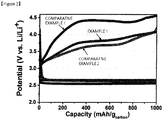
FIG. 2 shows data comparing charge and discharge curves of Example 1 and Comparative Examples 1 and 2 according to the present invention. -
FIG. 3 shows data comparing cycle capacity of Example 1 and Comparative Examples 1 and 2 according to the present invention. - The present invention aims to facilitate an oxidation and reduction reaction of oxygen by coating a surface of a carbon-based conductor, a positive electrode active material, with a side reaction prevention layer to block a contact with a liquid electrolyte, and introducing a metal catalyst thereto.
- Hereinafter, preferred examples of the present invention will be described in detail with reference to accompanying illustrative drawings. Such drawings correspond to one embodiment for describing the present invention, may be implemented in various different forms, and are not limited to the present specification. In the drawings, parts not relevant to the descriptions are not included in order to clearly describe the present invention, and like reference numerals are used for like elements throughout the specification. In addition, sizes and relative sizes of constituents shown in the drawings are unrelated to actual scales, and may be reduced or exaggerated for clarity of the descriptions.
- In the present specification, a numerical range expressed using ┌∼┘ expresses a range including values written before and after ┌∼┘ as a minimum value and a maximum value, respectively. In addition, in the present specification, ┌combination thereof┘ is a meaning including, unless stated otherwise, both mixing or combining two or more and applying these as one element, and applying each as an individual element, and each combination is considered as one type regardless of the application type.
-
FIG. 1 is a sectional diagram schematically illustrating a lithium-air battery provided in the present invention. When referring to this diagram to provide more specific descriptions, in the lithium-air battery formed including a positive electrode (100), a negative electrode (200), a separator (300) provided therebetween and a liquid electrolyte (400), the positive electrode (100) has a structure including a porous current collector (10); a carbon-based conductor (20) coated on one surface of the porous current collector (10); a side reaction prevention layer (30) coated on a surface of the carbon-based conductor (20); and a metal catalyst (40) sporadically partially introduced to a surface of the side reaction prevention layer (30). - In the present invention, introduced means, by electrostatic attraction or Van der Waals attraction between the side reaction prevention layer (30) and the metal catalyst (40), the metal catalyst (40) being led to the side reaction prevention layer (30) and being loaded as if being buried, or being coated.
- The porous current collector (10) of the present invention is a porous current collector having gas permeability, and may preferably include porous carbon pulp and porous carbon paper, and in addition thereto, may include porous three-dimensional current collectors such as foamed metal, metal fiber, porous metal, etched metal or metal having unevenness front and back, non-woven fabric, or the like. In addition, multiple pores may also be present inside the carbon-based conductor (20), and such pores have multiple active sites, a large pore volume and a high specific surface area by increasing permeability of air including oxygen, which is preferred in providing a positive electrode active site.
- In the present invention, the carbon-based conductor (20) is a nano unit-sized particle or structure, and using porous carbon powder or carbon structure having a large specific surface area and high electric conductivity is preferred. Examples thereof preferably include one type selected from the group consisting of graphite-based, active carbon-based, carbon black-based, carbon fiber-based, carbon nanostructure and combinations thereof, but are not limited thereto.
- Particularly, by coating the carbon-based conductor (20) described above using a conductive metal oxide as the side reaction prevention layer (30) in the present invention, deposition of side reaction products is to be suppressed through physically blocking the carbon-based conductor (20) with the liquid electrolyte (400). When the surface is modified by coating with such a conductive metal oxide, a low resistance property at the interface contributes to battery performance enhancement in addition to the interfacial reaction with the electrolyte.
- The conductive metal oxide according to the present invention may include one or more types selected from the group consisting of indium tin oxide (ITO), indium zinc oxide (IZO), antimony tin oxide (ATO), fluoro tin oxide (FTO), aluminum zinc oxide (AZO), magnesium indium oxide, gallium zinc oxide (GZO), gallium indium oxide, indium gallium zinc oxide (IGZO), niobium strontium titanium oxide (Nb-STO), indium cadmium oxide, boron zinc oxide (BZO), SZO(SiO2-ZnO), indium oxide (In2O3) and combinations thereof, and preferably, indium tin oxide (ITO) or indium zinc oxide (IZO) is used.
- Among the conductive metal oxides, transparent conductive oxides (TCO) having a large band gap, a low resistance value and high permeability in a visible region such as indium tin oxide (ITO) or indium zinc oxide (IZO) are used in solar cells, touch panels, heat mirrors, organic electroluminescence devices (OLED) and liquid crystal displays (LCD), and although these are metal oxides, they have electric conductivity equivalent to metals, and carbon defect portions are completely covered enabling physical blocking with the liquid electrolyte (400) while providing conductivity to a positive electrode, and therefore, these are most preferred as the side reaction prevention layer (30) of the present invention.
- In addition, the side reaction prevention layer (30) preferably has a thickness in a range of 5 nm ∼ 30 nm, and the thickness being less than 5 nm has a risk of the carbon-based conductor (20) being exposed to the liquid electrolyte (400), and the thickness being greater than 30 nm changes structures and reduces sizes of micropores of the carbon-based conductor (20) making it difficult to load large quantities of discharge products (for example Li2O2).
- As the metal catalyst (40) of the present invention, known metals or metal compounds capable of weakening or destroying lithium oxide (Li2O2 or Li2O) bonds produced when discharged are preferably used. For example, the metal catalyst (40) is ruthenium (Ru), palladium (Pd), platinum (Pt), gold (Au), nickel (Ni), copper (Cu), silver (Ag), zinc (Zn), lead (Pb), cadmium (Cd), tin (Sn), titanium (Ti) and an alloy thereof, an oxide thereof, a sulfide thereof or a selenide thereof, and preferably, ruthenium oxide (RuO2) is used.
- The metal catalyst (40) is included in 10 - 50 parts by weight with respect to 100 parts by weight of the carbon-based conductor (20), and as such a metal catalyst (40), using those having an average particle diameter of 1 nm ∼ 10 nm is preferred in securing effects of the present invention.
- A positive electrode for a lithium-air battery having the constituents described above may be prepared through i) coating a carbon conductor on a porous current collector; ii) depositing a conductive metal oxide on a surface of the carbon conductor as a side reaction prevention layer so as to include the carbon conductor; and iii) introducing a metal catalyst to the side reaction prevention layer. Hereinafter, each step will be described in detail.
- First, a carbon conductor is coated on a porous current collector. The carbon-based conductor described above and a binder are mixed in a weight ratio of 9:1 ∼ 7:3, and the result is dispersed into a solvent to prepare a slurry composition, and then the composition may be coated on a porous current collector and dried.
- The binder performs a role of facilitating binding between the carbon-based conductors, and fixing these on a current collector. In the present invention, the types are not particularly limited, and any binder known in the art may be used. For example, one type may be selected from the group consisting of acryl-based binders, fluorine resin-based binders, rubber-based binders, cellulose-based binders, polyalcohol-based binders, polyolefin-based binders, polyimide-based binders, polyester-based binders, silicone-based binders and combinations thereof. More specifically, polytetrafluoroethylene (PTFE), polyvinylidene fluoride (PVDF), a copolymer thereof or cellulose may be used, and even more preferably, polyvinylidene fluoride (PVDF) may be used.
- As a solvent for forming the slurry, water or an organic solvent may be used, and as the organic solvent, one type selected from the group consisting of isopropyl alcohol, N-methyl-2-pyrrolidone (NMP), acetone and combinations thereof may be used.
- Next, a side reaction prevention layer is formed by depositing a conductive metal oxide over the whole porous current collector surface so as to include the coated carbon-based conductor.
- Methods of coating on the porous base are not limited, and coating may be carried out using methods such as doctor blade coating, dip coating, gravure coating, slit die coating, spin coating, comma coating, bar coating, reverse roll coating, screen coating or cap coating.
- In addition, after the coating, the result may be dried for 12 hours ∼ 36 hours in a vacuum oven heated to 100°C ∼ 150°C. By evaporating the solvent included in the slurry through the drying, binding strength between the carbon-based conductor and the current collector is facilitated and the carbon-based conductor is evenly dispersed even into the inside frame of the porous current collector for binding.
- Next, a side reaction prevention layer is formed by depositing a conductive metal oxide over the whole porous current collector surface so as to include the coated carbon-based conductor. Preferably, one type selected from among the conductive metal oxides described above is dry deposited on the carbon-based conductor-coated porous current collector, and as one example, a method of sputtering or thermal evaporation deposition may be used for the deposition.
- More specifically, ion beam sputtering, DC-sputtering, RF-sputtering or thermal evaporation deposition may be used for the deposition, and such methods have high deposition rates at room temperature, release nontoxic gases, have operating easiness, have safety and the like, and deposition on large-area substrates may be achieved. In addition, such methods have advantages of readily controlling a side reaction prevention layer thickness, being low-priced compared to an atomic layer deposition (ALD) method, and mass producing relatively even deposition surfaces.
- Next, a positive electrode for a lithium-air battery is prepared by introducing a metal catalyst to the side reaction prevention layer. Methods of introducing a metal catalyst to the side reaction prevention layer are not limited, and as one example, a metal oxide may be introduced through repeating a process of immersing the prepared side reaction prevention layer-coated carbon-based conductor into a beaker filled with a metal precursor, and then immersing in distilled water. A metal oxide may be introduced through a simple process of obtaining metal cations in the beaker filled with a metal precursor, and obtaining oxygen anions in distilled water.
- A positive electrode prepared through the above-mentioned process is readily introduced to a lithium-air battery and fundamentally blocks a contact between an electrolyte and the carbon-based conductor.
- As illustrated in
FIG. 1 , the present invention provides a lithium-air battery including a positive electrode (100); a negative electrode (200); a separator (300) provided therebetween and a liquid electrolyte (400) impregnated thereinto. The lithium-air battery according to one embodiment of the present invention includes a separator provided on at least one surface of the porous coating layer according to the embodiments described above, and may have common constitutions and components of metal-air batteries. Herein, in the positive electrode (100), one surface of a porous current collector (10) on which a carbon-based conductor (20), a side reaction prevention layer (30) and a metal catalyst (40) are formed is preferably disposed to be impregnated into the liquid electrolyte (400). - When operating a lithium-air battery, a side reaction occurs by the electrodes (100, 200) and the liquid electrolyte (400) adjoining thereto. In other words, lithium ions and a solvent in the liquid electrolyte react to produce a lithium carbonate or lithium carboxylate material, and this causes battery property decline. The side reaction normally occurs in the positive electrode (100) rather than in the negative electrode (200). Accordingly, by disposing the side reaction prevention layer (30) and the metal catalyst (40) to be impregnated into the liquid electrolyte (400) in the present invention, the side reaction occurring in the positive electrode (100) is suppressed or decomposition of the produced reactant is facilitated. Moreover, an effect of enhancing electrochemical reactivity of the metal catalyst (40) itself is obtained resultantly enhancing a cycle property while increasing battery capacity of a lithium-air battery.
-
FIG. 1 schematically illustrates a sectional structure of a lithium-air battery according to one embodiment of the present invention. Herein, those known in the art may be used as the positive electrode, the negative electrode and the electrolyte. - The lithium-air battery of the present invention uses the positive electrode (100) described above, and although the thickness of the positive electrode (100) is not particularly limited, the thickness may be preferably 10 µm ∼ 100 µm, and more preferably, the thickness of the positive electrode may be 20 µm ∼ 60 µm.
- According to one embodiment of the present invention, a negative electrode active material of the negative electrode (200) may be selected from the group consisting of lithium metal, lithium metal-based alloys, lithium compounds and lithium intercalation materials.
- Particularly, the lithium metal-based alloy may be an alloy of lithium and one or more materials selected from the group consisting of, for example, Na, K, Rb, Cs, Fr, Be, Ma, Ca, Sr, Ba, Ra, Al and Sn, and the lithium compound may be a material reversibly forming a lithium-containing compound by reacting with lithium ions, and for example, may be tin oxide (SnO2), titanium nitrate (TiN) or Recon. In addition, the lithium intercalation material means a material capable of reversibly intercalating or deintercalating lithium ions, and for example, may be crystalline carbon, amorphous carbon or a mixture thereof.
- The thickness of the negative electrode (200) is not particularly limited, but may be 50 µm or greater. The upper limit of the negative electrode is not particularly limited, and it is more favorable as the thickness becomes larger, however, considering commercialization potential, the thickness of the negative electrode may be 50 µm ∼ 500 µm.
- A common separator (300) may be provided between the positive electrode (100) and the negative electrode (200). The separator (300) has a function of physically separating the electrodes, and those commonly used as a separator may be used without particular limit. Particularly, those having low resistance for ion migration of the liquid electrolyte, and having an excellent liquid electrolyte moisture-containing ability are preferred.
- In addition, the separator (300) enables lithium ion transport between the positive electrode and the negative electrode while separating and insulating the positive electrode (100) and the negative electrode (200). Such a separator (300) is porous and may be formed with non-conductive or insulating materials. The separator may be an independent member such as a film, or a coating layer added to the positive electrode and/or the negative electrode.
- Specifically, porous polymer films, for example, porous polymer films prepared with a polyolefin-based polymer such as an ethylene homopolymer, a propylene homopolymer, an ethylene/butene copolymer, an ethylene/hexene copolymer and an ethylene/methacrylate copolymer may be used either alone or as laminates thereof, or common porous non-woven fabrics, for example, non-woven fabrics made of high melting point glass fiber or polyethylene terephthalate fiber may be used, however, the separator is not limited thereto.
- According to one embodiment of the present invention, the liquid electrolyte (400) is a non-aqueous liquid electrolyte including an ionizable lithium salt and an organic solvent. For example, as the solvent of the non-aqueous liquid electrolyte, carbonate such as ethylene carbonate (EC) or propylene carbonate (PC), chain carbonate such as diethylene carbonate, ethers such as 1,2-dioxane, nitriles such as acetonitrile (AN), or amides may be used, however, the solvent is not limited thereto. These may be used either alone or as a combination of a plurality of these.
- In addition, as the lithium salt, one, two or more selected from the group consisting of LiPF6, LiBF4, LiSbF6, LiAsF6, LiN(SO2C2F5)2, Li(CF3SO2)2N, LiC4F9SO3, LiClO4, LiAlO2, LiAlCl4, LiF, LiBr, LiCl, LiI and LiB(C2O4)2, LiCF3SO3, LiN(SO2CF3)2(Li-TFSI), LiN(SO2C2F5)2 and LiC(SO2CF3)3 may be used, however, the lithium salt is not limited thereto. The lithium salt may be used in a concentration of 0.1 M ∼ 2.0 M range. When the lithium salt concentration is included in the above-mentioned range, an electrolyte has proper conductivity and viscosity, and therefore, excellent electrolyte performance may be exhibited and lithium ions may effectively migrate.
- The form of the lithium-air battery according to the present invention is not limited, and may be, for example, a coin-type, a plane-type, a cylinder-type, a horn-type, a button-type, a sheet-type or a laminate-type. The lithium-air battery may also be used in large-size batteries such as electric vehicles. In addition, the lithium-air battery according to the present invention may be used in both metal primary batteries and metal secondary batteries. The lithium-air battery may also be used in large-size batteries used in electric vehicles and the like. Furthermore, a battery module including the lithium-air battery according to the present invention as a unit cell may be manufactured.
- Hereinafter, the present invention will be more specifically described with reference to examples, however, the following examples do not limit the scope of the present invention, and are to be construed as for illuminating the present invention.
- To 0.8 g of a carbon-based conductor (CNT), 1.695 g of
kfl 100 dissolving a binder (PVDF) in a N-methyl-2-pyrrolidone (NMP) solvent was added to prepare primary slurry so that the conductor to the binder ratio became 8:2. After that, 25 g of N-methyl-2-pyrrolidone (NMP) was additionally added to prepare secondary slurry that is coatable. Blade coating was carried out on carbon paper using the secondary slurry. After the coating, the result was dried for 24 hours or longer in a vacuum oven heated to 120°C in advance. - In order to coat an indium tin oxide (ITO) layer as a side reaction prevention layer, a sputtering process was used. The deposition process was progressed at room temperature, and was progressed so as to have a thickness of approximately 10 nm under argon (Ar) atmosphere.
- In order to introduce a ruthenium oxide catalyst, a ruthenium precursor solution was prepared. In a beaker, a precursor solution dissolving ruthenium chloride (RuCl2) in distilled water so as to have a concentration of 10 mM was prepared. In another beaker, the distilled water was prepared in the same amount, and heated to 60°C.
- In
Step 2, a process of immersing and taking out the side reaction prevention layer-coated positive electrode in an aqueous solution including ruthenium ions and in distilled water heated to 60°C for 15 seconds and 30 seconds, respectively, was repeated 5 times. A separate washing process was not included since oxygen anions are loaded from the distilled water. The metal catalyst-introduced positive electrode for a lithium-air battery was dried for 24 hours or longer in a vacuum oven heated to 120°C in advance. - Using the positive electrode prepared in Step 3, a lithium-ion battery was assembled in a coin cell form in a glove box under argon (Ar) atmosphere. On a perforated lower plate made of stainless steel, a positive electrode, a separator (glass fiber), a lithium negative electrode, a gasket, a stainless steel coin, a spring and an upper plate were placed in order, and a pressure was applied to assemble a coin cell. As a liquid electrolyte, 1 M LiTFSI-dissolved tetraethylen glycol dimethyl ether (TEGDME) was used.
- A lithium-air battery was manufactured in the same manner as in Example 1 (except
Step 2 and Step 3) using a positive electrode coating only the carbon-based conductor. - A lithium-air battery was manufactured in the same manner as in Example 1 (except Step 2) using a positive electrode coating ruthenium oxide, a metal catalyst, on the carbon-based conductor.
- For the completed coin cells, a charge and discharge experiment was progressed under oxygen atmosphere of 1 atmosphere. The charge and discharge experiment was progressed at a charge/discharge rate of 0.3 C/0.1 C based on 1,000 mAh/g capacity with respect to the carbon weight. Comparison of charge and discharge curves and cycle capacity between the lithium-air batteries using the carbon-based conductor (CNT) positive electrode and the positive electrode loaded with the side reaction prevention layer and the catalyst layer is shown in
FIG. 2 andFIG. 3 . - When examining the charge and discharge curves in
FIG. 2 , the lithium-air battery of Example 1 had a lower voltage compared to the lithium-air battery of Comparative Example 1, and therefore, a decrease in the overvoltage was identified, and although a somewhat higher overvoltage was measured compared to Comparative Example 2, this turned out to be negligible. In addition, when examining the cycle capacity curves ofFIG. 3 , discharge capacity of Comparative Example 1 was greatly reduced when 30 cycles were progressed, and in Comparative Example 2, discharge capacity was greatly reduced even before progressing 20 cycles, whereas in Example 1, it was identified that initial discharge capacity was maintained until 50 cycles were progressed. - Hereinbefore, preferred Example 1 of the present invention have been described in detail, however, the scope of a right of the present invention is not limited thereto, and various modifications and improvements made by those skilled in the art using basic concepts of the present invention defined in the attached claims also belong to the scope of a right of the present invention.
- A battery pack including the lithium-sulfur battery may be used as a power supply of electric vehicles (EV), hybrid electric vehicles (HEV) and plug-in hybrid electric vehicles (PHEV), or systems for power storage.
Claims (11)
- A positive electrode for a lithium-air battery comprising:a porous current collector;a carbon-based conductor coated on one surface of the porous current collector;a side reaction prevention layer coated on a surface of the carbon-based conductor; anda metal catalyst sporadically partially introduced to a surface of the side reaction prevention layer,wherein the side reaction prevention layer includes a conductive metal oxide.
- The positive electrode for a lithium-air battery of Claim 1, wherein the conductive metal oxide includes one type selected from the group consisting of indium tin oxide, indium zinc oxide, antimony tin oxide, fluorinated tin oxide, aluminum zinc oxide, magnesium indium oxide, zinc gallium oxide, gallium indium oxide, indium-gallium-zinc oxide, niobium-strontium-titanium oxide, indium cadmium oxide, BZO, SZO, indium oxide and combinations thereof.
- The positive electrode for a lithium-air battery of Claim 1, wherein the side reaction prevention layer has a thickness of 5 nm - 30 nm.
- The positive electrode for a lithium-air battery of Claim 1, wherein the carbon-based conductor includes one type selected from the group consisting of graphite-based, active carbon-based, carbon black-based, carbon fiber, carbon nanostructures and combinations thereof.
- The positive electrode for a lithium-air battery of Claim 1, wherein the metal catalyst is ruthenium, palladium, platinum, gold, nickel, copper, silver, zinc, lead, cadmium, tin, titanium and an alloy thereof, an oxide thereof, a sulfide thereof or a selenium thereof.
- The positive electrode for a lithium-air battery of Claim 1, wherein the metal catalyst is included in 10 ∼ 50 parts by weight with respect to 100 parts by weight of the carbon-based conductor.
- The positive electrode for a lithium-air battery of Claim 1, wherein the metal catalyst has an average particle diameter of 1 nm ∼ 10 nm.
- A method for preparing a positive electrode for a lithium-air battery comprising:i) coating a carbon-based conductor on a porous current collector;ii) depositing a side reaction prevention layer on a surface of the carbon-based conductor; andiii) introducing a metal catalyst to the side reaction prevention layer,wherein the side reaction prevention layer includes a conductive metal oxide.
- The method for preparing a positive electrode for a lithium-air battery of Claim 8, wherein the deposition in ii) is carried out using sputtering or thermal evaporation deposition.
- The method for preparing a positive electrode for a lithium-air battery of Claim 8, wherein the conductive metal oxide includes one type selected from the group consisting of indium tin oxide, indium zinc oxide, antimony tin oxide, fluorinated tin oxide, aluminum zinc oxide, magnesium indium oxide, zinc gallium oxide, gallium indium oxide, indium-gallium-zinc oxide, niobium-strontium-titanium oxide, indium cadmium oxide, BZO, SZO, indium oxide and combinations thereof.
- A lithium-air battery comprising:a lithium negative electrode;a positive electrode;a separator provided therebetween; andan electrolyte,wherein the positive electrode is the positive electrode for a lithium-air battery of any one of Claims 1 to 7.
Applications Claiming Priority (2)
| Application Number | Priority Date | Filing Date | Title |
|---|---|---|---|
| KR20160006885 | 2016-01-20 | ||
| PCT/KR2017/000535 WO2017126855A1 (en) | 2016-01-20 | 2017-01-16 | Positive electrode of lithium-air battery having side reaction prevention film to which metal catalyst is partially introduced, lithium-air battery having same, and manufacturing method therefor |
Publications (3)
| Publication Number | Publication Date |
|---|---|
| EP3316366A4 EP3316366A4 (en) | 2018-05-02 |
| EP3316366A1 true EP3316366A1 (en) | 2018-05-02 |
| EP3316366B1 EP3316366B1 (en) | 2018-12-12 |
Family
ID=59422540
Family Applications (1)
| Application Number | Title | Priority Date | Filing Date |
|---|---|---|---|
| EP17741621.1A Active EP3316366B1 (en) | 2016-01-20 | 2017-01-16 | Positive electrode of lithium-air battery having side reaction prevention film to which metal catalyst is partially introduced, lithium-air battery having same, and manufacturing method therefor |
Country Status (5)
| Country | Link |
|---|---|
| US (1) | US10505203B2 (en) |
| EP (1) | EP3316366B1 (en) |
| JP (1) | JP6494854B2 (en) |
| KR (1) | KR102024899B1 (en) |
| CN (1) | CN108028392B (en) |
Cited By (2)
| Publication number | Priority date | Publication date | Assignee | Title |
|---|---|---|---|---|
| EP3435458A1 (en) * | 2017-07-26 | 2019-01-30 | Samsung Electronics Co., Ltd. | Metal-air battery including a gas diffusion layer, and method of manufacturing the metal-air battery |
| EP3817099A1 (en) * | 2019-10-30 | 2021-05-05 | Samsung Electronics Co., Ltd. | Cathode and metal-air battery including the same |
Families Citing this family (2)
| Publication number | Priority date | Publication date | Assignee | Title |
|---|---|---|---|---|
| KR102602422B1 (en) * | 2018-10-11 | 2023-11-14 | 현대자동차주식회사 | Lithium air battery and manufacturing method thereof |
| KR20210048291A (en) | 2019-10-23 | 2021-05-03 | 삼성전자주식회사 | Cathode for metal air battery, preparing method thereof, and metal air battery comprising the same |
Family Cites Families (20)
| Publication number | Priority date | Publication date | Assignee | Title |
|---|---|---|---|---|
| DE3573493D1 (en) * | 1984-02-24 | 1989-11-09 | Toshiba Kk | Oxygen permeable membrane |
| JP4415241B2 (en) * | 2001-07-31 | 2010-02-17 | 日本電気株式会社 | Negative electrode for secondary battery, secondary battery using the same, and method for producing negative electrode |
| CN1306637C (en) * | 2004-11-11 | 2007-03-21 | 南亚塑胶工业股份有限公司 | Air electrode of multi-layer sintering structure and its manufacturing method |
| KR101274818B1 (en) * | 2008-01-08 | 2013-06-13 | 주식회사 엘지화학 | Cathode for battery, method for manufacturing thereof, and lithium secondary battery comprising the same |
| JP5198080B2 (en) * | 2008-01-31 | 2013-05-15 | 株式会社オハラ | Solid battery |
| KR101244578B1 (en) * | 2009-01-26 | 2013-03-25 | 도요타 지도샤(주) | Air battery |
| KR101338142B1 (en) * | 2010-04-27 | 2013-12-06 | 한양대학교 산학협력단 | Lithium air battery |
| EP2577793A1 (en) * | 2010-05-28 | 2013-04-10 | Toyota Jidosha Kabushiki Kaisha | Cathode catalyst for rechargeable metal-air battery and rechargeable metal-air battery |
| CA2812405A1 (en) * | 2010-09-24 | 2012-03-29 | The Government Of The United States Of America, As Represented By The Se Cretary Of The Navy | Dual-function air cathode nanoarchitectures for metal-air batteries with pulse-power capability |
| CN102074709B (en) * | 2010-12-17 | 2013-10-16 | 武汉泓元伟力新能源科技有限公司 | Air electrode, preparation method thereof and metal air battery provided with air electrode |
| KR101227796B1 (en) | 2011-01-11 | 2013-01-29 | 경기대학교 산학협력단 | Carbon sphere-catalytic oxide nano composites for lithium-air secondary battery and manufacturing method of the same |
| US9088049B2 (en) * | 2012-01-23 | 2015-07-21 | Florida State University Research Foundation, Inc. | Bifunctional hollandite Ag2Mn8O16 catalyst for lithium-air batteries |
| KR101309577B1 (en) | 2012-04-18 | 2013-09-17 | 연세대학교 산학협력단 | Cathode for li-air cell and li-air cell including the same |
| KR20140030482A (en) | 2012-08-30 | 2014-03-12 | 한국과학기술연구원 | A cathode for lithium air secondary battery, a fabricating method thereof and lithium air secondary battery using the same |
| KR20140039755A (en) | 2012-09-25 | 2014-04-02 | 현대자동차주식회사 | Mixed oxide catalyst, cathode for lithium air battery and lithium air battery including the same |
| JP2014075269A (en) | 2012-10-04 | 2014-04-24 | Toyota Motor Corp | Metal-air battery |
| KR101955040B1 (en) | 2012-10-19 | 2019-03-07 | 한양대학교 산학협력단 | Cathode for lithium-air battery, method of manufacturing the same and lithium-air battery including the same |
| KR101622092B1 (en) | 2013-08-22 | 2016-05-18 | 주식회사 엘지화학 | Cathode Active Material for Metal-Air Cell and Metal-Air Cell Comprising The Same |
| US9954231B2 (en) | 2013-09-13 | 2018-04-24 | Lg Chem, Ltd. | Positive electrode for lithium-air battery and method for preparing the same |
| KR101599124B1 (en) * | 2014-03-05 | 2016-03-15 | 한국과학기술원 | Perovskite metal oxide nanofibers as air electrode for lithium air batteries, and fabrication method thereof |
-
2017
- 2017-01-16 KR KR1020170007064A patent/KR102024899B1/en active IP Right Grant
- 2017-01-16 CN CN201780003170.7A patent/CN108028392B/en active Active
- 2017-01-16 US US15/743,387 patent/US10505203B2/en active Active
- 2017-01-16 EP EP17741621.1A patent/EP3316366B1/en active Active
- 2017-01-16 JP JP2018500714A patent/JP6494854B2/en active Active
Cited By (3)
| Publication number | Priority date | Publication date | Assignee | Title |
|---|---|---|---|---|
| EP3435458A1 (en) * | 2017-07-26 | 2019-01-30 | Samsung Electronics Co., Ltd. | Metal-air battery including a gas diffusion layer, and method of manufacturing the metal-air battery |
| US10707495B2 (en) | 2017-07-26 | 2020-07-07 | Samsung Electronics Co., Ltd. | Gas diffusion layer for metal-air battery, metal-air battery including the gas diffusion layer, and method of manufacturing the metal-air battery |
| EP3817099A1 (en) * | 2019-10-30 | 2021-05-05 | Samsung Electronics Co., Ltd. | Cathode and metal-air battery including the same |
Also Published As
| Publication number | Publication date |
|---|---|
| CN108028392A (en) | 2018-05-11 |
| KR20170087411A (en) | 2017-07-28 |
| EP3316366B1 (en) | 2018-12-12 |
| JP6494854B2 (en) | 2019-04-03 |
| US10505203B2 (en) | 2019-12-10 |
| KR102024899B1 (en) | 2019-09-24 |
| CN108028392B (en) | 2021-08-17 |
| EP3316366A4 (en) | 2018-05-02 |
| JP2018520487A (en) | 2018-07-26 |
| US20180212256A1 (en) | 2018-07-26 |
Similar Documents
| Publication | Publication Date | Title |
|---|---|---|
| JP6862527B2 (en) | Self-assembled composite of carbon nitride and graphene oxide, positive electrode to which this is applied, and lithium-sulfur battery containing it | |
| Wang et al. | Dendrite-free Na metal plating/stripping onto 3D porous Cu hosts | |
| KR102470625B1 (en) | Nano-engineered coatings for anode active materials, cathode active materials, and solid-state electrolytes and methods of making batteries containing nano-engineered coatings | |
| EP3580171B1 (en) | Passivation of lithium metal by two-dimensional materials for rechargeable batteries | |
| KR101632793B1 (en) | Cathode for lithium air battery and method for manufacturing the same | |
| US20230253545A1 (en) | Anodes, cathodes, and separators for batteries and methods to make and use same | |
| JP2015503189A (en) | Aqueous electrolyte lithium-sulfur battery | |
| US10505203B2 (en) | Positive electrode of lithium-air battery having side reaction prevention film to which metal catalyst is partially introduced, lithium-air battery having same, and manufacturing method therefor | |
| EP3509158B1 (en) | Aqueous electrolyte solution, and aqueous lithium ion secondary battery | |
| JP2003303618A (en) | Non-aqueous electrolyte battery | |
| Usui et al. | Anode properties of Ru-coated Si thick film electrodes prepared by gas-deposition | |
| WO2016147607A1 (en) | Anode for sodium-ion and potassium-ion batteries | |
| US9742027B2 (en) | Anode for sodium-ion and potassium-ion batteries | |
| US9379379B2 (en) | Cathode material for lithium ion secondary batteries, cathode member for lithium ion secondary batteries, lithium ion secondary battery, and method for producing cathode material for lithium ion secondary batteries | |
| Li et al. | Metal–air batteries: a review on current status and future applications | |
| JP2020522852A (en) | Positive electrode for lithium-sulfur battery and lithium-sulfur battery including the same | |
| US9843080B2 (en) | Magnesium-based methods, systems, and devices | |
| KR20210115843A (en) | Electrolyte for lithium metal battery and lithium metal battery comprising the same | |
| EP4160734A1 (en) | Lithium secondary cell and non-aqueous electrolyte used for same | |
| KR102620768B1 (en) | Multi-layered negative electrode and secondary battery comprising the same | |
| KR102207523B1 (en) | Lithium secondary battery | |
| WO2022073035A1 (en) | Electrochemical cells including anodes comprising a protective layer, and related methods | |
| WO2017126855A1 (en) | Positive electrode of lithium-air battery having side reaction prevention film to which metal catalyst is partially introduced, lithium-air battery having same, and manufacturing method therefor | |
| KR20230140664A (en) | Negative electrode with protective layer and secondary battery comprising the same | |
| CN117790793A (en) | Hybrid electrode design for high energy batteries |
Legal Events
| Date | Code | Title | Description |
|---|---|---|---|
| STAA | Information on the status of an ep patent application or granted ep patent |
Free format text: STATUS: THE INTERNATIONAL PUBLICATION HAS BEEN MADE |
|
| PUAI | Public reference made under article 153(3) epc to a published international application that has entered the european phase |
Free format text: ORIGINAL CODE: 0009012 |
|
| STAA | Information on the status of an ep patent application or granted ep patent |
Free format text: STATUS: REQUEST FOR EXAMINATION WAS MADE |
|
| 17P | Request for examination filed |
Effective date: 20180123 |
|
| A4 | Supplementary search report drawn up and despatched |
Effective date: 20180302 |
|
| AK | Designated contracting states |
Kind code of ref document: A1 Designated state(s): AL AT BE BG CH CY CZ DE DK EE ES FI FR GB GR HR HU IE IS IT LI LT LU LV MC MK MT NL NO PL PT RO RS SE SI SK SM TR |
|
| AX | Request for extension of the european patent |
Extension state: BA ME |
|
| GRAP | Despatch of communication of intention to grant a patent |
Free format text: ORIGINAL CODE: EPIDOSNIGR1 |
|
| STAA | Information on the status of an ep patent application or granted ep patent |
Free format text: STATUS: GRANT OF PATENT IS INTENDED |
|
| RIC1 | Information provided on ipc code assigned before grant |
Ipc: H01M 12/06 20060101ALI20180824BHEP Ipc: H01M 4/96 20060101ALI20180824BHEP Ipc: H01M 4/86 20060101AFI20180824BHEP Ipc: H01M 4/38 20060101ALI20180824BHEP Ipc: H01M 4/88 20060101ALI20180824BHEP |
|
| DAV | Request for validation of the european patent (deleted) | ||
| DAX | Request for extension of the european patent (deleted) | ||
| INTG | Intention to grant announced |
Effective date: 20180926 |
|
| GRAS | Grant fee paid |
Free format text: ORIGINAL CODE: EPIDOSNIGR3 |
|
| GRAA | (expected) grant |
Free format text: ORIGINAL CODE: 0009210 |
|
| STAA | Information on the status of an ep patent application or granted ep patent |
Free format text: STATUS: THE PATENT HAS BEEN GRANTED |
|
| AK | Designated contracting states |
Kind code of ref document: B1 Designated state(s): AL AT BE BG CH CY CZ DE DK EE ES FI FR GB GR HR HU IE IS IT LI LT LU LV MC MK MT NL NO PL PT RO RS SE SI SK SM TR |
|
| REG | Reference to a national code |
Ref country code: GB Ref legal event code: FG4D |
|
| REG | Reference to a national code |
Ref country code: CH Ref legal event code: EP |
|
| REG | Reference to a national code |
Ref country code: AT Ref legal event code: REF Ref document number: 1077179 Country of ref document: AT Kind code of ref document: T Effective date: 20181215 |
|
| REG | Reference to a national code |
Ref country code: DE Ref legal event code: R096 Ref document number: 602017001387 Country of ref document: DE |
|
| REG | Reference to a national code |
Ref country code: IE Ref legal event code: FG4D |
|
| REG | Reference to a national code |
Ref country code: NL Ref legal event code: MP Effective date: 20181212 |
|
| REG | Reference to a national code |
Ref country code: LT Ref legal event code: MG4D |
|
| PG25 | Lapsed in a contracting state [announced via postgrant information from national office to epo] |
Ref country code: FI Free format text: LAPSE BECAUSE OF FAILURE TO SUBMIT A TRANSLATION OF THE DESCRIPTION OR TO PAY THE FEE WITHIN THE PRESCRIBED TIME-LIMIT Effective date: 20181212 Ref country code: BG Free format text: LAPSE BECAUSE OF FAILURE TO SUBMIT A TRANSLATION OF THE DESCRIPTION OR TO PAY THE FEE WITHIN THE PRESCRIBED TIME-LIMIT Effective date: 20190312 Ref country code: HR Free format text: LAPSE BECAUSE OF FAILURE TO SUBMIT A TRANSLATION OF THE DESCRIPTION OR TO PAY THE FEE WITHIN THE PRESCRIBED TIME-LIMIT Effective date: 20181212 Ref country code: LV Free format text: LAPSE BECAUSE OF FAILURE TO SUBMIT A TRANSLATION OF THE DESCRIPTION OR TO PAY THE FEE WITHIN THE PRESCRIBED TIME-LIMIT Effective date: 20181212 Ref country code: ES Free format text: LAPSE BECAUSE OF FAILURE TO SUBMIT A TRANSLATION OF THE DESCRIPTION OR TO PAY THE FEE WITHIN THE PRESCRIBED TIME-LIMIT Effective date: 20181212 Ref country code: LT Free format text: LAPSE BECAUSE OF FAILURE TO SUBMIT A TRANSLATION OF THE DESCRIPTION OR TO PAY THE FEE WITHIN THE PRESCRIBED TIME-LIMIT Effective date: 20181212 Ref country code: NO Free format text: LAPSE BECAUSE OF FAILURE TO SUBMIT A TRANSLATION OF THE DESCRIPTION OR TO PAY THE FEE WITHIN THE PRESCRIBED TIME-LIMIT Effective date: 20190312 |
|
| REG | Reference to a national code |
Ref country code: AT Ref legal event code: MK05 Ref document number: 1077179 Country of ref document: AT Kind code of ref document: T Effective date: 20181212 |
|
| PG25 | Lapsed in a contracting state [announced via postgrant information from national office to epo] |
Ref country code: GR Free format text: LAPSE BECAUSE OF FAILURE TO SUBMIT A TRANSLATION OF THE DESCRIPTION OR TO PAY THE FEE WITHIN THE PRESCRIBED TIME-LIMIT Effective date: 20190313 Ref country code: RS Free format text: LAPSE BECAUSE OF FAILURE TO SUBMIT A TRANSLATION OF THE DESCRIPTION OR TO PAY THE FEE WITHIN THE PRESCRIBED TIME-LIMIT Effective date: 20181212 Ref country code: AL Free format text: LAPSE BECAUSE OF FAILURE TO SUBMIT A TRANSLATION OF THE DESCRIPTION OR TO PAY THE FEE WITHIN THE PRESCRIBED TIME-LIMIT Effective date: 20181212 Ref country code: SE Free format text: LAPSE BECAUSE OF FAILURE TO SUBMIT A TRANSLATION OF THE DESCRIPTION OR TO PAY THE FEE WITHIN THE PRESCRIBED TIME-LIMIT Effective date: 20181212 |
|
| PG25 | Lapsed in a contracting state [announced via postgrant information from national office to epo] |
Ref country code: NL Free format text: LAPSE BECAUSE OF FAILURE TO SUBMIT A TRANSLATION OF THE DESCRIPTION OR TO PAY THE FEE WITHIN THE PRESCRIBED TIME-LIMIT Effective date: 20181212 |
|
| PG25 | Lapsed in a contracting state [announced via postgrant information from national office to epo] |
Ref country code: IT Free format text: LAPSE BECAUSE OF FAILURE TO SUBMIT A TRANSLATION OF THE DESCRIPTION OR TO PAY THE FEE WITHIN THE PRESCRIBED TIME-LIMIT Effective date: 20181212 Ref country code: PL Free format text: LAPSE BECAUSE OF FAILURE TO SUBMIT A TRANSLATION OF THE DESCRIPTION OR TO PAY THE FEE WITHIN THE PRESCRIBED TIME-LIMIT Effective date: 20181212 Ref country code: CZ Free format text: LAPSE BECAUSE OF FAILURE TO SUBMIT A TRANSLATION OF THE DESCRIPTION OR TO PAY THE FEE WITHIN THE PRESCRIBED TIME-LIMIT Effective date: 20181212 Ref country code: PT Free format text: LAPSE BECAUSE OF FAILURE TO SUBMIT A TRANSLATION OF THE DESCRIPTION OR TO PAY THE FEE WITHIN THE PRESCRIBED TIME-LIMIT Effective date: 20190412 |
|
| PG25 | Lapsed in a contracting state [announced via postgrant information from national office to epo] |
Ref country code: SK Free format text: LAPSE BECAUSE OF FAILURE TO SUBMIT A TRANSLATION OF THE DESCRIPTION OR TO PAY THE FEE WITHIN THE PRESCRIBED TIME-LIMIT Effective date: 20181212 Ref country code: EE Free format text: LAPSE BECAUSE OF FAILURE TO SUBMIT A TRANSLATION OF THE DESCRIPTION OR TO PAY THE FEE WITHIN THE PRESCRIBED TIME-LIMIT Effective date: 20181212 Ref country code: RO Free format text: LAPSE BECAUSE OF FAILURE TO SUBMIT A TRANSLATION OF THE DESCRIPTION OR TO PAY THE FEE WITHIN THE PRESCRIBED TIME-LIMIT Effective date: 20181212 Ref country code: SM Free format text: LAPSE BECAUSE OF FAILURE TO SUBMIT A TRANSLATION OF THE DESCRIPTION OR TO PAY THE FEE WITHIN THE PRESCRIBED TIME-LIMIT Effective date: 20181212 Ref country code: IS Free format text: LAPSE BECAUSE OF FAILURE TO SUBMIT A TRANSLATION OF THE DESCRIPTION OR TO PAY THE FEE WITHIN THE PRESCRIBED TIME-LIMIT Effective date: 20190412 |
|
| REG | Reference to a national code |
Ref country code: DE Ref legal event code: R097 Ref document number: 602017001387 Country of ref document: DE |
|
| PG25 | Lapsed in a contracting state [announced via postgrant information from national office to epo] |
Ref country code: LU Free format text: LAPSE BECAUSE OF NON-PAYMENT OF DUE FEES Effective date: 20190116 |
|
| REG | Reference to a national code |
Ref country code: BE Ref legal event code: MM Effective date: 20190131 |
|
| PLBE | No opposition filed within time limit |
Free format text: ORIGINAL CODE: 0009261 |
|
| STAA | Information on the status of an ep patent application or granted ep patent |
Free format text: STATUS: NO OPPOSITION FILED WITHIN TIME LIMIT |
|
| REG | Reference to a national code |
Ref country code: IE Ref legal event code: MM4A |
|
| PG25 | Lapsed in a contracting state [announced via postgrant information from national office to epo] |
Ref country code: MC Free format text: LAPSE BECAUSE OF FAILURE TO SUBMIT A TRANSLATION OF THE DESCRIPTION OR TO PAY THE FEE WITHIN THE PRESCRIBED TIME-LIMIT Effective date: 20181212 Ref country code: AT Free format text: LAPSE BECAUSE OF FAILURE TO SUBMIT A TRANSLATION OF THE DESCRIPTION OR TO PAY THE FEE WITHIN THE PRESCRIBED TIME-LIMIT Effective date: 20181212 Ref country code: DK Free format text: LAPSE BECAUSE OF FAILURE TO SUBMIT A TRANSLATION OF THE DESCRIPTION OR TO PAY THE FEE WITHIN THE PRESCRIBED TIME-LIMIT Effective date: 20181212 |
|
| 26N | No opposition filed |
Effective date: 20190913 |
|
| PG25 | Lapsed in a contracting state [announced via postgrant information from national office to epo] |
Ref country code: BE Free format text: LAPSE BECAUSE OF NON-PAYMENT OF DUE FEES Effective date: 20190131 |
|
| PG25 | Lapsed in a contracting state [announced via postgrant information from national office to epo] |
Ref country code: IE Free format text: LAPSE BECAUSE OF NON-PAYMENT OF DUE FEES Effective date: 20190116 |
|
| PG25 | Lapsed in a contracting state [announced via postgrant information from national office to epo] |
Ref country code: TR Free format text: LAPSE BECAUSE OF FAILURE TO SUBMIT A TRANSLATION OF THE DESCRIPTION OR TO PAY THE FEE WITHIN THE PRESCRIBED TIME-LIMIT Effective date: 20181212 |
|
| PG25 | Lapsed in a contracting state [announced via postgrant information from national office to epo] |
Ref country code: MT Free format text: LAPSE BECAUSE OF NON-PAYMENT OF DUE FEES Effective date: 20190116 |
|
| REG | Reference to a national code |
Ref country code: CH Ref legal event code: PL |
|
| PG25 | Lapsed in a contracting state [announced via postgrant information from national office to epo] |
Ref country code: CH Free format text: LAPSE BECAUSE OF NON-PAYMENT OF DUE FEES Effective date: 20200131 Ref country code: LI Free format text: LAPSE BECAUSE OF NON-PAYMENT OF DUE FEES Effective date: 20200131 |
|
| PG25 | Lapsed in a contracting state [announced via postgrant information from national office to epo] |
Ref country code: CY Free format text: LAPSE BECAUSE OF FAILURE TO SUBMIT A TRANSLATION OF THE DESCRIPTION OR TO PAY THE FEE WITHIN THE PRESCRIBED TIME-LIMIT Effective date: 20181212 |
|
| PG25 | Lapsed in a contracting state [announced via postgrant information from national office to epo] |
Ref country code: HU Free format text: LAPSE BECAUSE OF FAILURE TO SUBMIT A TRANSLATION OF THE DESCRIPTION OR TO PAY THE FEE WITHIN THE PRESCRIBED TIME-LIMIT; INVALID AB INITIO Effective date: 20170116 |
|
| PG25 | Lapsed in a contracting state [announced via postgrant information from national office to epo] |
Ref country code: SI Free format text: LAPSE BECAUSE OF FAILURE TO SUBMIT A TRANSLATION OF THE DESCRIPTION OR TO PAY THE FEE WITHIN THE PRESCRIBED TIME-LIMIT Effective date: 20181212 |
|
| PG25 | Lapsed in a contracting state [announced via postgrant information from national office to epo] |
Ref country code: MK Free format text: LAPSE BECAUSE OF FAILURE TO SUBMIT A TRANSLATION OF THE DESCRIPTION OR TO PAY THE FEE WITHIN THE PRESCRIBED TIME-LIMIT Effective date: 20181212 |
|
| PGFP | Annual fee paid to national office [announced via postgrant information from national office to epo] |
Ref country code: DE Payment date: 20221220 Year of fee payment: 7 |
|
| P01 | Opt-out of the competence of the unified patent court (upc) registered |
Effective date: 20230408 |
|
| REG | Reference to a national code |
Ref country code: DE Ref legal event code: R081 Ref document number: 602017001387 Country of ref document: DE Owner name: LG ENERGY SOLUTION, LTD., KR Free format text: FORMER OWNER: LG CHEM, LTD., SEOUL, KR |
|
| REG | Reference to a national code |
Ref country code: GB Ref legal event code: 732E Free format text: REGISTERED BETWEEN 20230824 AND 20230831 |
|
| PGFP | Annual fee paid to national office [announced via postgrant information from national office to epo] |
Ref country code: GB Payment date: 20231220 Year of fee payment: 8 |
|
| PGFP | Annual fee paid to national office [announced via postgrant information from national office to epo] |
Ref country code: FR Payment date: 20231222 Year of fee payment: 8 |