EP3435458A1 - Metal-air battery including a gas diffusion layer, and method of manufacturing the metal-air battery - Google Patents
Metal-air battery including a gas diffusion layer, and method of manufacturing the metal-air battery Download PDFInfo
- Publication number
- EP3435458A1 EP3435458A1 EP18176472.1A EP18176472A EP3435458A1 EP 3435458 A1 EP3435458 A1 EP 3435458A1 EP 18176472 A EP18176472 A EP 18176472A EP 3435458 A1 EP3435458 A1 EP 3435458A1
- Authority
- EP
- European Patent Office
- Prior art keywords
- layer
- carbon fibers
- metal
- gas diffusion
- positive electrode
- Prior art date
- Legal status (The legal status is an assumption and is not a legal conclusion. Google has not performed a legal analysis and makes no representation as to the accuracy of the status listed.)
- Granted
Links
- 238000009792 diffusion process Methods 0.000 title claims abstract description 147
- 238000004519 manufacturing process Methods 0.000 title claims description 35
- 229920000049 Carbon (fiber) Polymers 0.000 claims abstract description 187
- 239000004917 carbon fiber Substances 0.000 claims abstract description 187
- 239000007789 gas Substances 0.000 claims abstract description 145
- 239000003792 electrolyte Substances 0.000 claims abstract description 51
- 229910052751 metal Inorganic materials 0.000 claims abstract description 28
- 239000002184 metal Substances 0.000 claims abstract description 28
- QVGXLLKOCUKJST-UHFFFAOYSA-N atomic oxygen Chemical compound [O] QVGXLLKOCUKJST-UHFFFAOYSA-N 0.000 claims abstract description 20
- 229910052760 oxygen Inorganic materials 0.000 claims abstract description 20
- 239000001301 oxygen Substances 0.000 claims abstract description 20
- 239000011149 active material Substances 0.000 claims abstract description 7
- VNWKTOKETHGBQD-UHFFFAOYSA-N methane Chemical compound C VNWKTOKETHGBQD-UHFFFAOYSA-N 0.000 claims description 44
- 238000003825 pressing Methods 0.000 claims description 12
- 238000000034 method Methods 0.000 claims description 10
- 239000010410 layer Substances 0.000 description 345
- 239000011230 binding agent Substances 0.000 description 21
- 238000003780 insertion Methods 0.000 description 21
- 230000037431 insertion Effects 0.000 description 21
- 230000000052 comparative effect Effects 0.000 description 19
- OKTJSMMVPCPJKN-UHFFFAOYSA-N Carbon Chemical compound [C] OKTJSMMVPCPJKN-UHFFFAOYSA-N 0.000 description 13
- 238000000926 separation method Methods 0.000 description 9
- -1 LiN(SO2C2F5)2 Chemical class 0.000 description 8
- 238000005452 bending Methods 0.000 description 5
- QSZMZKBZAYQGRS-UHFFFAOYSA-N lithium;bis(trifluoromethylsulfonyl)azanide Chemical compound [Li+].FC(F)(F)S(=O)(=O)[N-]S(=O)(=O)C(F)(F)F QSZMZKBZAYQGRS-UHFFFAOYSA-N 0.000 description 5
- 150000003839 salts Chemical class 0.000 description 5
- 229910052799 carbon Inorganic materials 0.000 description 4
- 239000000835 fiber Substances 0.000 description 4
- 229910002804 graphite Inorganic materials 0.000 description 4
- 239000010439 graphite Substances 0.000 description 4
- 229910003473 lithium bis(trifluoromethanesulfonyl)imide Inorganic materials 0.000 description 4
- 229910003002 lithium salt Inorganic materials 0.000 description 4
- 159000000002 lithium salts Chemical class 0.000 description 4
- 238000005259 measurement Methods 0.000 description 4
- 229910021645 metal ion Inorganic materials 0.000 description 4
- 229920000642 polymer Polymers 0.000 description 4
- 239000002904 solvent Substances 0.000 description 4
- PXHVJJICTQNCMI-UHFFFAOYSA-N Nickel Chemical compound [Ni] PXHVJJICTQNCMI-UHFFFAOYSA-N 0.000 description 3
- 239000004743 Polypropylene Substances 0.000 description 3
- DNIAPMSPPWPWGF-UHFFFAOYSA-N Propylene glycol Chemical compound CC(O)CO DNIAPMSPPWPWGF-UHFFFAOYSA-N 0.000 description 3
- 239000003054 catalyst Substances 0.000 description 3
- 239000004020 conductor Substances 0.000 description 3
- 238000002156 mixing Methods 0.000 description 3
- 239000004745 nonwoven fabric Substances 0.000 description 3
- BASFCYQUMIYNBI-UHFFFAOYSA-N platinum Chemical compound [Pt] BASFCYQUMIYNBI-UHFFFAOYSA-N 0.000 description 3
- 229920001155 polypropylene Polymers 0.000 description 3
- 229920001343 polytetrafluoroethylene Polymers 0.000 description 3
- 239000004810 polytetrafluoroethylene Substances 0.000 description 3
- TWRXJAOTZQYOKJ-UHFFFAOYSA-L Magnesium chloride Chemical compound [Mg+2].[Cl-].[Cl-] TWRXJAOTZQYOKJ-UHFFFAOYSA-L 0.000 description 2
- 239000002033 PVDF binder Substances 0.000 description 2
- 229920003171 Poly (ethylene oxide) Polymers 0.000 description 2
- 239000004698 Polyethylene Substances 0.000 description 2
- WCUXLLCKKVVCTQ-UHFFFAOYSA-M Potassium chloride Chemical compound [Cl-].[K+] WCUXLLCKKVVCTQ-UHFFFAOYSA-M 0.000 description 2
- FAPWRFPIFSIZLT-UHFFFAOYSA-M Sodium chloride Chemical compound [Na+].[Cl-] FAPWRFPIFSIZLT-UHFFFAOYSA-M 0.000 description 2
- VSCWAEJMTAWNJL-UHFFFAOYSA-K aluminium trichloride Chemical compound Cl[Al](Cl)Cl VSCWAEJMTAWNJL-UHFFFAOYSA-K 0.000 description 2
- 239000011575 calcium Substances 0.000 description 2
- 239000002041 carbon nanotube Substances 0.000 description 2
- 229910021393 carbon nanotube Inorganic materials 0.000 description 2
- 239000003575 carbonaceous material Substances 0.000 description 2
- 238000007599 discharging Methods 0.000 description 2
- 239000011267 electrode slurry Substances 0.000 description 2
- 239000010408 film Substances 0.000 description 2
- 239000010931 gold Substances 0.000 description 2
- 229910052744 lithium Inorganic materials 0.000 description 2
- 239000011777 magnesium Substances 0.000 description 2
- 239000011572 manganese Substances 0.000 description 2
- 239000007769 metal material Substances 0.000 description 2
- 230000003647 oxidation Effects 0.000 description 2
- 238000007254 oxidation reaction Methods 0.000 description 2
- 229920000573 polyethylene Polymers 0.000 description 2
- 229920002981 polyvinylidene fluoride Polymers 0.000 description 2
- 239000011148 porous material Substances 0.000 description 2
- IOLCXVTUBQKXJR-UHFFFAOYSA-M potassium bromide Chemical compound [K+].[Br-] IOLCXVTUBQKXJR-UHFFFAOYSA-M 0.000 description 2
- 239000002356 single layer Substances 0.000 description 2
- 239000011734 sodium Substances 0.000 description 2
- JHJLBTNAGRQEKS-UHFFFAOYSA-M sodium bromide Chemical compound [Na+].[Br-] JHJLBTNAGRQEKS-UHFFFAOYSA-M 0.000 description 2
- OYPRJOBELJOOCE-UHFFFAOYSA-N Calcium Chemical compound [Ca] OYPRJOBELJOOCE-UHFFFAOYSA-N 0.000 description 1
- UXVMQQNJUSDDNG-UHFFFAOYSA-L Calcium chloride Chemical compound [Cl-].[Cl-].[Ca+2] UXVMQQNJUSDDNG-UHFFFAOYSA-L 0.000 description 1
- MYMOFIZGZYHOMD-UHFFFAOYSA-N Dioxygen Chemical compound O=O MYMOFIZGZYHOMD-UHFFFAOYSA-N 0.000 description 1
- DGAQECJNVWCQMB-PUAWFVPOSA-M Ilexoside XXIX Chemical compound C[C@@H]1CC[C@@]2(CC[C@@]3(C(=CC[C@H]4[C@]3(CC[C@@H]5[C@@]4(CC[C@@H](C5(C)C)OS(=O)(=O)[O-])C)C)[C@@H]2[C@]1(C)O)C)C(=O)O[C@H]6[C@@H]([C@H]([C@@H]([C@H](O6)CO)O)O)O.[Na+] DGAQECJNVWCQMB-PUAWFVPOSA-M 0.000 description 1
- XEEYBQQBJWHFJM-UHFFFAOYSA-N Iron Chemical compound [Fe] XEEYBQQBJWHFJM-UHFFFAOYSA-N 0.000 description 1
- 229910013375 LiC Inorganic materials 0.000 description 1
- 229910001559 LiC4F9SO3 Inorganic materials 0.000 description 1
- 229910000552 LiCF3SO3 Inorganic materials 0.000 description 1
- 229910013385 LiN(SO2C2F5)2 Inorganic materials 0.000 description 1
- 229910013406 LiN(SO2CF3)2 Inorganic materials 0.000 description 1
- 229910013436 LiN(SO3CF3)2 Inorganic materials 0.000 description 1
- 229910001290 LiPF6 Inorganic materials 0.000 description 1
- WHXSMMKQMYFTQS-UHFFFAOYSA-N Lithium Chemical compound [Li] WHXSMMKQMYFTQS-UHFFFAOYSA-N 0.000 description 1
- HBBGRARXTFLTSG-UHFFFAOYSA-N Lithium ion Chemical compound [Li+] HBBGRARXTFLTSG-UHFFFAOYSA-N 0.000 description 1
- FYYHWMGAXLPEAU-UHFFFAOYSA-N Magnesium Chemical compound [Mg] FYYHWMGAXLPEAU-UHFFFAOYSA-N 0.000 description 1
- PWHULOQIROXLJO-UHFFFAOYSA-N Manganese Chemical compound [Mn] PWHULOQIROXLJO-UHFFFAOYSA-N 0.000 description 1
- 239000004734 Polyphenylene sulfide Substances 0.000 description 1
- ZLMJMSJWJFRBEC-UHFFFAOYSA-N Potassium Chemical compound [K] ZLMJMSJWJFRBEC-UHFFFAOYSA-N 0.000 description 1
- BQCADISMDOOEFD-UHFFFAOYSA-N Silver Chemical compound [Ag] BQCADISMDOOEFD-UHFFFAOYSA-N 0.000 description 1
- 150000001336 alkenes Chemical class 0.000 description 1
- 239000000956 alloy Substances 0.000 description 1
- 229910045601 alloy Inorganic materials 0.000 description 1
- 229910052782 aluminium Inorganic materials 0.000 description 1
- XAGFODPZIPBFFR-UHFFFAOYSA-N aluminium Chemical compound [Al] XAGFODPZIPBFFR-UHFFFAOYSA-N 0.000 description 1
- 230000005540 biological transmission Effects 0.000 description 1
- 229910052791 calcium Inorganic materials 0.000 description 1
- 239000001110 calcium chloride Substances 0.000 description 1
- 229910001628 calcium chloride Inorganic materials 0.000 description 1
- 239000006229 carbon black Substances 0.000 description 1
- 238000006243 chemical reaction Methods 0.000 description 1
- 239000011248 coating agent Substances 0.000 description 1
- 238000000576 coating method Methods 0.000 description 1
- 229910017052 cobalt Inorganic materials 0.000 description 1
- 239000010941 cobalt Substances 0.000 description 1
- GUTLYIVDDKVIGB-UHFFFAOYSA-N cobalt atom Chemical compound [Co] GUTLYIVDDKVIGB-UHFFFAOYSA-N 0.000 description 1
- 239000002131 composite material Substances 0.000 description 1
- 230000007423 decrease Effects 0.000 description 1
- 238000000151 deposition Methods 0.000 description 1
- 229910001882 dioxygen Inorganic materials 0.000 description 1
- 238000001035 drying Methods 0.000 description 1
- 239000008151 electrolyte solution Substances 0.000 description 1
- 238000003912 environmental pollution Methods 0.000 description 1
- 238000011156 evaluation Methods 0.000 description 1
- PCHJSUWPFVWCPO-UHFFFAOYSA-N gold Chemical compound [Au] PCHJSUWPFVWCPO-UHFFFAOYSA-N 0.000 description 1
- 229910052737 gold Inorganic materials 0.000 description 1
- 229910021389 graphene Inorganic materials 0.000 description 1
- 229910001385 heavy metal Inorganic materials 0.000 description 1
- 150000002500 ions Chemical class 0.000 description 1
- 238000004898 kneading Methods 0.000 description 1
- 229910001547 lithium hexafluoroantimonate(V) Inorganic materials 0.000 description 1
- 229910001540 lithium hexafluoroarsenate(V) Inorganic materials 0.000 description 1
- 229910001416 lithium ion Inorganic materials 0.000 description 1
- MHCFAGZWMAWTNR-UHFFFAOYSA-M lithium perchlorate Chemical compound [Li+].[O-]Cl(=O)(=O)=O MHCFAGZWMAWTNR-UHFFFAOYSA-M 0.000 description 1
- 229910001486 lithium perchlorate Inorganic materials 0.000 description 1
- 229910001537 lithium tetrachloroaluminate Inorganic materials 0.000 description 1
- 229910001496 lithium tetrafluoroborate Inorganic materials 0.000 description 1
- 229910052749 magnesium Inorganic materials 0.000 description 1
- 229910001629 magnesium chloride Inorganic materials 0.000 description 1
- 229910052748 manganese Inorganic materials 0.000 description 1
- 239000000463 material Substances 0.000 description 1
- 229910052759 nickel Inorganic materials 0.000 description 1
- JRZJOMJEPLMPRA-UHFFFAOYSA-N olefin Natural products CCCCCCCC=C JRZJOMJEPLMPRA-UHFFFAOYSA-N 0.000 description 1
- 239000011368 organic material Substances 0.000 description 1
- 230000001590 oxidative effect Effects 0.000 description 1
- 229910052697 platinum Inorganic materials 0.000 description 1
- 229920000069 polyphenylene sulfide Polymers 0.000 description 1
- 229910052700 potassium Inorganic materials 0.000 description 1
- 239000011591 potassium Substances 0.000 description 1
- 239000001103 potassium chloride Substances 0.000 description 1
- 239000000843 powder Substances 0.000 description 1
- 238000011160 research Methods 0.000 description 1
- 239000011347 resin Substances 0.000 description 1
- 229920005989 resin Polymers 0.000 description 1
- 229910052709 silver Inorganic materials 0.000 description 1
- 239000004332 silver Substances 0.000 description 1
- 229910052708 sodium Inorganic materials 0.000 description 1
- 239000011780 sodium chloride Substances 0.000 description 1
- 239000007784 solid electrolyte Substances 0.000 description 1
- 239000007790 solid phase Substances 0.000 description 1
- 239000000243 solution Substances 0.000 description 1
- 229920003048 styrene butadiene rubber Polymers 0.000 description 1
- 239000000126 substance Substances 0.000 description 1
- JBQYATWDVHIOAR-UHFFFAOYSA-N tellanylidenegermanium Chemical compound [Te]=[Ge] JBQYATWDVHIOAR-UHFFFAOYSA-N 0.000 description 1
- 239000010409 thin film Substances 0.000 description 1
Images


Classifications
-
- H—ELECTRICITY
- H01—ELECTRIC ELEMENTS
- H01M—PROCESSES OR MEANS, e.g. BATTERIES, FOR THE DIRECT CONVERSION OF CHEMICAL ENERGY INTO ELECTRICAL ENERGY
- H01M4/00—Electrodes
- H01M4/86—Inert electrodes with catalytic activity, e.g. for fuel cells
- H01M4/8605—Porous electrodes
- H01M4/8626—Porous electrodes characterised by the form
-
- H—ELECTRICITY
- H01—ELECTRIC ELEMENTS
- H01M—PROCESSES OR MEANS, e.g. BATTERIES, FOR THE DIRECT CONVERSION OF CHEMICAL ENERGY INTO ELECTRICAL ENERGY
- H01M4/00—Electrodes
- H01M4/86—Inert electrodes with catalytic activity, e.g. for fuel cells
- H01M4/8647—Inert electrodes with catalytic activity, e.g. for fuel cells consisting of more than one material, e.g. consisting of composites
- H01M4/8657—Inert electrodes with catalytic activity, e.g. for fuel cells consisting of more than one material, e.g. consisting of composites layered
-
- H—ELECTRICITY
- H01—ELECTRIC ELEMENTS
- H01M—PROCESSES OR MEANS, e.g. BATTERIES, FOR THE DIRECT CONVERSION OF CHEMICAL ENERGY INTO ELECTRICAL ENERGY
- H01M4/00—Electrodes
- H01M4/86—Inert electrodes with catalytic activity, e.g. for fuel cells
- H01M4/88—Processes of manufacture
- H01M4/8803—Supports for the deposition of the catalytic active composition
- H01M4/8807—Gas diffusion layers
-
- H—ELECTRICITY
- H01—ELECTRIC ELEMENTS
- H01M—PROCESSES OR MEANS, e.g. BATTERIES, FOR THE DIRECT CONVERSION OF CHEMICAL ENERGY INTO ELECTRICAL ENERGY
- H01M10/00—Secondary cells; Manufacture thereof
- H01M10/05—Accumulators with non-aqueous electrolyte
- H01M10/052—Li-accumulators
- H01M10/0525—Rocking-chair batteries, i.e. batteries with lithium insertion or intercalation in both electrodes; Lithium-ion batteries
-
- H—ELECTRICITY
- H01—ELECTRIC ELEMENTS
- H01M—PROCESSES OR MEANS, e.g. BATTERIES, FOR THE DIRECT CONVERSION OF CHEMICAL ENERGY INTO ELECTRICAL ENERGY
- H01M12/00—Hybrid cells; Manufacture thereof
- H01M12/04—Hybrid cells; Manufacture thereof composed of a half-cell of the fuel-cell type and of a half-cell of the primary-cell type
- H01M12/06—Hybrid cells; Manufacture thereof composed of a half-cell of the fuel-cell type and of a half-cell of the primary-cell type with one metallic and one gaseous electrode
-
- H—ELECTRICITY
- H01—ELECTRIC ELEMENTS
- H01M—PROCESSES OR MEANS, e.g. BATTERIES, FOR THE DIRECT CONVERSION OF CHEMICAL ENERGY INTO ELECTRICAL ENERGY
- H01M12/00—Hybrid cells; Manufacture thereof
- H01M12/08—Hybrid cells; Manufacture thereof composed of a half-cell of a fuel-cell type and a half-cell of the secondary-cell type
-
- H—ELECTRICITY
- H01—ELECTRIC ELEMENTS
- H01M—PROCESSES OR MEANS, e.g. BATTERIES, FOR THE DIRECT CONVERSION OF CHEMICAL ENERGY INTO ELECTRICAL ENERGY
- H01M4/00—Electrodes
- H01M4/02—Electrodes composed of, or comprising, active material
- H01M4/13—Electrodes for accumulators with non-aqueous electrolyte, e.g. for lithium-accumulators; Processes of manufacture thereof
- H01M4/134—Electrodes based on metals, Si or alloys
-
- H—ELECTRICITY
- H01—ELECTRIC ELEMENTS
- H01M—PROCESSES OR MEANS, e.g. BATTERIES, FOR THE DIRECT CONVERSION OF CHEMICAL ENERGY INTO ELECTRICAL ENERGY
- H01M4/00—Electrodes
- H01M4/02—Electrodes composed of, or comprising, active material
- H01M4/36—Selection of substances as active materials, active masses, active liquids
- H01M4/38—Selection of substances as active materials, active masses, active liquids of elements or alloys
- H01M4/381—Alkaline or alkaline earth metals elements
- H01M4/382—Lithium
-
- H—ELECTRICITY
- H01—ELECTRIC ELEMENTS
- H01M—PROCESSES OR MEANS, e.g. BATTERIES, FOR THE DIRECT CONVERSION OF CHEMICAL ENERGY INTO ELECTRICAL ENERGY
- H01M4/00—Electrodes
- H01M4/86—Inert electrodes with catalytic activity, e.g. for fuel cells
- H01M4/8605—Porous electrodes
-
- H—ELECTRICITY
- H01—ELECTRIC ELEMENTS
- H01M—PROCESSES OR MEANS, e.g. BATTERIES, FOR THE DIRECT CONVERSION OF CHEMICAL ENERGY INTO ELECTRICAL ENERGY
- H01M4/00—Electrodes
- H01M4/86—Inert electrodes with catalytic activity, e.g. for fuel cells
- H01M4/96—Carbon-based electrodes
-
- H—ELECTRICITY
- H01—ELECTRIC ELEMENTS
- H01M—PROCESSES OR MEANS, e.g. BATTERIES, FOR THE DIRECT CONVERSION OF CHEMICAL ENERGY INTO ELECTRICAL ENERGY
- H01M8/00—Fuel cells; Manufacture thereof
- H01M8/02—Details
- H01M8/0202—Collectors; Separators, e.g. bipolar separators; Interconnectors
- H01M8/023—Porous and characterised by the material
- H01M8/0234—Carbonaceous material
-
- H—ELECTRICITY
- H01—ELECTRIC ELEMENTS
- H01M—PROCESSES OR MEANS, e.g. BATTERIES, FOR THE DIRECT CONVERSION OF CHEMICAL ENERGY INTO ELECTRICAL ENERGY
- H01M8/00—Fuel cells; Manufacture thereof
- H01M8/10—Fuel cells with solid electrolytes
- H01M8/1004—Fuel cells with solid electrolytes characterised by membrane-electrode assemblies [MEA]
-
- H—ELECTRICITY
- H01—ELECTRIC ELEMENTS
- H01M—PROCESSES OR MEANS, e.g. BATTERIES, FOR THE DIRECT CONVERSION OF CHEMICAL ENERGY INTO ELECTRICAL ENERGY
- H01M4/00—Electrodes
- H01M4/86—Inert electrodes with catalytic activity, e.g. for fuel cells
- H01M2004/8678—Inert electrodes with catalytic activity, e.g. for fuel cells characterised by the polarity
- H01M2004/8689—Positive electrodes
-
- Y—GENERAL TAGGING OF NEW TECHNOLOGICAL DEVELOPMENTS; GENERAL TAGGING OF CROSS-SECTIONAL TECHNOLOGIES SPANNING OVER SEVERAL SECTIONS OF THE IPC; TECHNICAL SUBJECTS COVERED BY FORMER USPC CROSS-REFERENCE ART COLLECTIONS [XRACs] AND DIGESTS
- Y02—TECHNOLOGIES OR APPLICATIONS FOR MITIGATION OR ADAPTATION AGAINST CLIMATE CHANGE
- Y02E—REDUCTION OF GREENHOUSE GAS [GHG] EMISSIONS, RELATED TO ENERGY GENERATION, TRANSMISSION OR DISTRIBUTION
- Y02E60/00—Enabling technologies; Technologies with a potential or indirect contribution to GHG emissions mitigation
- Y02E60/10—Energy storage using batteries
-
- Y—GENERAL TAGGING OF NEW TECHNOLOGICAL DEVELOPMENTS; GENERAL TAGGING OF CROSS-SECTIONAL TECHNOLOGIES SPANNING OVER SEVERAL SECTIONS OF THE IPC; TECHNICAL SUBJECTS COVERED BY FORMER USPC CROSS-REFERENCE ART COLLECTIONS [XRACs] AND DIGESTS
- Y02—TECHNOLOGIES OR APPLICATIONS FOR MITIGATION OR ADAPTATION AGAINST CLIMATE CHANGE
- Y02E—REDUCTION OF GREENHOUSE GAS [GHG] EMISSIONS, RELATED TO ENERGY GENERATION, TRANSMISSION OR DISTRIBUTION
- Y02E60/00—Enabling technologies; Technologies with a potential or indirect contribution to GHG emissions mitigation
- Y02E60/30—Hydrogen technology
- Y02E60/50—Fuel cells
Definitions
- the present disclosure relates to a metal-air battery including a gas diffusion layer, and a method of manufacturing the metal-air battery. More particularly, the present disclosure relates to a gas diffusion layer for metal-air batteries having an increased energy density, a metal-air battery including the gas diffusion layer, and a method of manufacturing the metal-air battery.
- Metal-air batteries include a negative electrode capable of absorbing/releasing ions and a positive electrode that uses oxygen from the air as an active material.
- reduction/oxidation of oxygen introduced from the outside occurs at the positive electrode
- oxidation/reduction of a metal occurs at the negative electrode
- the chemical energy generated by these reactions is extracted as electrical energy.
- the metal-air batteries absorb oxygen during discharging and release oxygen during charge. Since the metal-air batteries use oxygen from the atmosphere, the metal-air batteries may have dramatically-increased energy densities, compared to other types of secondary batteries.
- the metal-air batteries may have an energy density that is several times greater than an energy density of lithium-ion batteries.
- the metal-air batteries since there is a low possibility of ignition of the metal-air batteries at an abnormally high temperature, the metal-air batteries have excellent stability. Also, since the metal-air batteries operate only by storing/releasing oxygen and do not use a heavy metal, the risk of causing environmental pollution is low. Due to such various advantages, much research has been conducted on metal-air batteries.
- a gas diffusion layer for metal-air batteries with increased energy density by reducing a weight per unit area of the gas diffusion layer a metal-air battery including the gas diffusion layer, and a method of manufacturing the metal-air battery.
- a metal-air battery includes at least one positive electrode layer, which is configured for using oxygen as an active material and includes a first surface and a second surface opposite the first surface; a gas diffusion layer on the first surface of the positive electrode layer and including a plurality of carbon fibers; an electrolyte layer on the second surface of the positive electrode layer; and a negative electrode metal layer on the electrolyte layer, wherein the positive electrode layer includes a plurality of grooves and portions of the plurality of carbon fibers are in the grooves.
- An average depth of each of the plurality of grooves may be about 20 % to about 60 % of a diameter of each of the plurality of carbon fibers.
- An average width of each of the plurality of grooves may be about 80 % to about 100 % of a diameter of a carbon fiber of the plurality of carbon fibers.
- An average length of each of the plurality of grooves may be greater than or equal to about 3 millimeters
- An average distance between adjacent grooves of the plurality of grooves may be about 30 micrometers to about 1,000 micrometers.
- a diameter of each of the plurality of carbon fibers may be about 5 micrometers to about 10 micrometers.
- a weight per unit area of the gas diffusion layer may be less than or equal to about 0.5 milligrams per square centimeter.
- the weight per unit area of the gas diffusion layer may be greater than or equal to about 0.007 milligrams per square centimeter.
- the gas diffusion layer may include a first carbon fiber layer including a plurality of carbon fibers arranged on the positive electrode layer, and a second carbon fiber layer on the first carbon fiber layer and including a plurality of carbon fibers extending in a direction intersecting a direction in which each of the plurality of carbon fibers of the first carbon fiber layer extends.
- the gas diffusion layer may include a fold.
- the gas diffusion layer may include a plurality of carbon fiber layers including a plurality of carbon fibers, and the plurality of carbon fiber layers may include less than or equal to four layers.
- the gas diffusion layer may be partially on the positive electrode layer.
- the negative electrode metal layer, the electrolyte layer, and the positive electrode layer may be bent over the gas diffusion layer such that the positive electrode layer contacts three surfaces of the gas diffusion layer, and one surface of the gas diffusion layer may be exposed.
- a method of manufacturing a metal-air battery includes: arranging a plurality of carbon fibers on a first surface of a positive electrode layer, which is configured for using oxygen as an active material; pressing the plurality of carbon fibers toward the positive electrode layer such that portions of the plurality of carbon fibers are inserted into the first surface of the positive electrode layer to form grooves, to thereby form a gas diffusion layer; and providing an electrolyte layer on a second surface of the positive electrode layer and a negative electrode metal layer on the electrolyte layer to form the metal-air battery.
- the pressing of the plurality of carbon fibers may include pressing the plurality of carbon fibers such that an average depth of the grooves is about 20 % to about 60 % of a diameter of a carbon fiber of the plurality of carbon fibers.
- the pressing of the plurality of carbon fibers may include pressing the plurality of carbon fibers such that an average width of the grooves is about 80 % to about 100 % of a diameter of a carbon fiber of the plurality of carbon fibers.
- the arranging of the plurality of carbon fibers may include arranging the plurality of carbon fibers such that an average distance between adjacent carbon fibers of the plurality of carbon fibers is about 30 micrometers to about 1,000 micrometers.
- a weight per unit area of the gas diffusion layer may be less than or equal to about 0.5 milligrams per square centimeter.
- the weight per unit area of the gas diffusion layer may be greater than or equal to about 0.007 milligrams per square centimeter.
- a gas diffusion layer includes a plurality of carbon fibers arranged on a first surface of a positive electrode layer which is configured for using oxygen as an active material, wherein portions of the plurality of carbon fibers are in the first surface of the positive electrode layer.
- the gas diffusion layer may include no binders.
- a gas diffusion layer for metal-air batteries, a metal-air battery, and a method of manufacturing the metal-air battery, according to an embodiment, will now be described in detail with reference to the accompanying drawings.
- Like reference numerals in the drawings denote like elements, and, in the drawings, the sizes or thicknesses of elements may be exaggerated for convenience of explanation.
- embodiments below may have different forms and should not be construed as being limited to the descriptions set forth herein.
- relative terms such as “lower” or “bottom” and “upper” or “top,” may be used herein to describe one element's relationship to another element as illustrated in the Figures. It will be understood that relative terms are intended to encompass different orientations of the device in addition to the orientation depicted in the Figures. For example, if the device in one of the figures is turned over, elements described as being on the “lower” side of other elements would then be oriented on “upper” sides of the other elements. The exemplary term “lower,” can therefore, encompasses both an orientation of “lower” and “upper,” depending on the particular orientation of the figure.
- Exemplary embodiments are described herein with reference to cross section illustrations that are schematic illustrations of idealized embodiments. As such, variations from the shapes of the illustrations as a result, for example, of manufacturing techniques and/or tolerances, are to be expected. Thus, embodiments described herein should not be construed as limited to the particular shapes of regions as illustrated herein but are to include deviations in shapes that result, for example, from manufacturing. For example, a region illustrated or described as flat may, typically, have rough and/or nonlinear features. Moreover, sharp angles that are illustrated may be rounded. Thus, the regions illustrated in the figures are schematic in nature and their shapes are not intended to illustrate the precise shape of a region and are not intended to limit the scope of the present claims.
- FIG. 1 is a cross-sectional view of an embodiment of a metal-air battery 1.
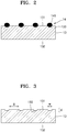
- FIG. 2 is a magnified view of a portion of the gas diffusion layer 14 of FIG. 1 .
- FIG. 3 is a cross-sectional view of the positive electrode layer 13 of FIG. 2 , not including the gas diffusion layer 14.
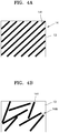
- FIG. 4A is a plan view of an embodiment of a gas diffusion layer 14, and
- FIG. 4B is a plan view of an embodiment of a gas diffusion layer 14A.
- the metal-air battery 1 may have a two-dimensional ("2D") planar structure.
- the metal-air battery 1 may be obtained by sequentially depositing a negative electrode metal layer 11, an electrolyte layer 12, a positive electrode layer 13, and the gas diffusion layer 14 for metal-air batteries (hereinafter, referred to as the gas diffusion layer 14).
- the metal-air battery 1 may further include an outer casing (not shown) that surrounds a portion of the metal-air battery 1 except for an upper surface of the gas diffusion layer 14.
- the negative electrode metal layer 11 functions to absorb/release metal ions, and may include, for example, lithium (Li), sodium (Na), zinc (Zn), potassium (K), calcium (Ca), magnesium (Mg), iron (Fe), aluminum (Al), an alloy thereof, or a combination thereof.
- the electrolyte layer 12 functions to transmit metal ions to the positive electrode layer 13.
- the electrolyte layer 12 may be referred to as a negative electrode electrolyte layer.
- the electrolyte layer 12 may include an electrolyte that is formed by dissolving a metal salt in a solvent.
- the electrolyte may be typically in a solid phase including a polymer-based electrolyte, an inorganic electrolyte, or a composite electrolyte obtained by mixing the polymer-based electrolyte with the inorganic electrolyte.
- the electrolyte layer 12 may be prepared in a bent form.
- the metal salt may be a lithium salt such as LiN(SO 2 C 2 F 5 ) 2 , LiClO 4 , LiBF 4 , LiPF 6 , LiSbF 6 , LiAsF 6 , LiCF 3 SO 3 , LiN(SO 2 CF 3 ) 2 , LiC(SO 2 CF 3 ) 3 , LiN(SO 3 CF 3 ) 2 , LiC 4 F 9 SO 3 , LiAlCl 4 , lithium bis(trifluoromethanesulfonyl)imide (“LiTFSI”), or a combination thereof.
- LiTFSI lithium bis(trifluoromethanesulfonyl)imide
- Another metal salt such as AlCl 3 , MgCl 2 , NaCl, KCl, NaBr, KBr, CaCl 2 , or a combination thereof may be added to the lithium salt.
- the solvent may be any material as long as it may dissolve the lithium salt and the another metal salt.
- the electrolyte layer 12 may further include a separation layer that prevents transmission of oxygen and has conductivity with respect to the metal ions.
- the separation layer may be a polymer-based separation film that may be bent.
- the separation layer may be formed of a polymer nonwoven fabric, such as a nonwoven fabric of polypropylene or a nonwoven fabric of polyphenylene sulfide, or a porous film of olefin-based resin, such as polyethylene or polypropylene.
- the separation layer and the electrolyte may be formed as separate layers, or the electrolytic layer 12 may be formed as one layer by impregnating pores of a porous separation layer with an electrolyte.
- the electrolytic layer 12 may be formed by impregnating the pores of a porous separation layer with an electrolyte formed by mixing polyethylene oxide ("PEO") with LiTFSI.
- PEO polyethylene oxide
- the positive electrode layer 13 may include an electrolyte for conducting the metal ions, a catalyst for oxidizing/reducing oxygen, a conductive material, and a binder.
- the positive electrode layer 13 may be formed by preparing a positive electrode slurry by mixing the electrolyte, the catalyst, the conductive material, and the binder, adding a solvent, for example, propylene glycol thereto, and coating and drying the positive electrode slurry on the electrolytic layer 12.
- the electrolyte may include the lithium salt or the another metal salt.
- the conductive material may be a porous carbon-based material, a conductive metal material, a conductive organic material, or a combination thereof.
- the carbon-based material may be carbon black, graphite, graphene, activated carbon, carbon fiber, carbon nanotubes, or a combination thereof.
- the conductive metal material may be used in the form of metal powder.
- the catalyst may be platinum (Pt), gold (Au), silver (Ag), or a combination thereof, or may be an oxide of manganese (Mn), nickel (Ni), cobalt (Co), or a combination thereof.
- the binder may be, for example, polytetrafluoroethylene (“PTFE”), polypropylene, polyvinylidene fluoride (“PVDF”), polyethylene, styrene-butadiene rubber, or a combination thereof.
- PTFE polytetrafluoroethylene
- PVDF polyvinylidene fluoride
- polyethylene polyethylene
- styrene-butadiene rubber or a combination thereof.
- the positive electrode layer 13 has a first surface 131 and a second surface 132 opposite the first surface 131.
- the gas diffusion layer 14 is disposed on the first surface 131 of the positive electrode layer 13, and the electrolyte layer 12 is disposed on the second surface 132.
- the gas diffusion layer 14 functions to absorb oxygen from the atmosphere and supply the oxygen to the positive electrode layer 13.
- the gas diffusion layer 14 may have a structure for moving and diffusing external oxygen, e.g., smoothly moving and diffusing external oxygen.
- the gas diffusion layer 14 may have a flow path structure.
- the gas diffusion layer 14 may have conductivity.
- the first thin film layer may include a plurality of carbon fibers 141.
- Each of the plurality of carbon fibers 141 may include carbon as a main component and have a diameter of less than or equal to about 20 micrometers ( ⁇ m).
- each of the carbon fibers 141 may have a diameter of about 5 ⁇ m to about 10 ⁇ m.
- the carbon fibers 141 may be referred to as graphite fibers.
- the carbon fibers 141 may be hollow carbon fibers.
- Each of the carbon fibers 141 may have a length of greater than or equal to about 3 millimeters (mm).
- a length of the plurality of carbon fibers 141 may be less than or equal to about 1,000 mm.
- the length of each of the carbon fibers 141 may be determined based on a length of the positive electrode layer 13 on which the gas diffusion layer 14 is disposed. For example, when the positive electrode layer 13 is long, long carbon fibers 141 may be used, and, when the positive electrode layer 13 is short, short carbon fibers 141 may be used.
- a weight of the gas diffusion layer 14 may be less than or equal to about 19 %, e.g., about 1 % to about 19%, of an overall weight of the metal-air battery 1.
- the gas diffusion layer 14 may include no binders. Since the gas diffusion layer 14 includes no binders, a weight per unit area, of the gas diffusion layer 14 may be reduced. For example, the weight per unit area of the gas diffusion layer 14 may be less than or equal to about 0.5 milligrams per square centimeter (mg/cm 2 ), e.g., about 0.007 mg/cm 2 to about 0.5 mg/cm 2 .
- the gas diffusion layer 14 of the present application includes no binders, when the plurality of carbon fibers 141 are arranged on the first surface 131 of the positive electrode layer 13 without any special actions, the plurality of carbon fibers 141 may not be fixed to the positive electrode layer 13 and may become scattered or move during the manufacture of the gas diffusion layer 14.
- respective portions of the plurality of carbon fibers 141 may be inserted into the positive electrode layer 13 such that the plurality of carbon fibers 141 may be fixed to the positive electrode layer 13.
- the positive electrode layer 13 may have insertion grooves 133 into which the respective portions of the carbon fibers 141 are inserted. Due to this insertion of the respective portions of the carbon fibers 141 of the gas diffusion layer 14 into the insertion grooves 133 of the positive electrode layer 13, the gas diffusion layer 14 may be fixed to the positive electrode layer 13.
- the insertion grooves 133 of the positive electrode layer 13 may have depths, widths, lengths, and gaps that enable the carbon fibers 141 of the gas diffusion layer 14 to be fixed to the positive electrode layer 13 and also enable oxygen to be sufficiently supplied and diffused.
- an average depth d of the insertion grooves 133 may be about 20 % to about 60 % of a diameter of a carbon fiber of the plurality of carbon fibers 141 or each of the carbon fibers 141.
- each of the insertion grooves 133 may have an average depth d of greater than or equal to about 1.4 ⁇ m.
- an average width w of the insertion grooves 133 may be about 80 % to about 100 % of the diameter of a carbon fiber of the plurality of carbon fibers 141 or each of the carbon fibers 141.
- An average length of each of the insertion grooves 133 may be greater than or equal to about 3 mm.
- An average gap g between adjacent insertion grooves of the plurality of insertion grooves 133 may be about 30 ⁇ m to about 1,000 ⁇ m.
- the gas diffusion layer 14 may include a first space occupied by the carbon fibers 141, and a second space in which no carbon fibers 141 are arranged and oxygen gas is movable and diffusible. A ratio of the second space to the gas diffusion layer 14 may be about 80 % to about 99 %.
- the gas diffusion layer 14 may have a single layer structure.
- the plurality of carbon fibers 141 may be arranged on the positive electrode layer 13 to form a single layer.
- the plurality of carbon fibers 141 extend in a uniform direction and may be spaced apart from each other.
- the arrangement of the plurality of carbon fibers 141 is not limited thereto, and the plurality of carbon fibers 141 may be arranged in various manners.
- the plurality of carbon fibers 141 of the gas diffusion layer 14A extend in various directions and may be arranged to be at least partially spaced apart from each other.
- the plurality of carbon fibers 141 are inserted into the insertion grooves 133 of the positive electrode layer 13 and fixed to the positive electrode layer 13, and thus the weight per unit area may be reduced to less than or equal to about 0.5 mg/cm 2 , e.g., about 0.007 mg/cm 2 to about 0.5 mg/cm 2 , and an energy density of the metal-air battery 1 may be increased.
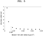
- FIG. 5 is a graph showing a voltage loss versus a weight per unit area of the gas diffusion layer 14.
- the gas diffusion layer 14 may have a weight per unit area of greater than or equal to about 0.007 mg/cm 2 so that a voltage loss due to a resistance in ohms is less than or equal to about 1 millivolt (mV).
- FIG. 6 is a cross-sectional view of an embodiment of a metal-air battery 1B.
- FIG. 7 is a magnified view of a portion of the gas diffusion layer 14B of FIG. 6 .
- FIG. 8A is a plan view of an embodiment of a diffusion layer 14B, and
- FIG. 8B is a plan view of an embodiment of a gas diffusion layer 14C.
- the metal-air battery 1B may include the negative electrode metal layer 11, the electrolyte layer 12, the positive electrode layer 13, and the gas diffusion layer 14B.
- the same component as that in the previous embodiments uses the same reference numeral, and a redundant description thereof will be omitted here.
- the gas diffusion layer 14B has a two-layer structure, and carbon fiber layers 140 and 150 may include a plurality of carbon fibers 141 and a plurality of carbon fibers 151, respectively. Each of the carbon fiber layers 140 and 150 include no binders. In the gas diffusion layer 14B having a two-layer structure, the plurality of carbon fibers 141 and 151 may be arranged in a lattice shape.
- the gas diffusion layer 14B may include a first carbon fiber layer 140 in which respective portions of the plurality of carbon fibers 141 are inserted into the insertion grooves 133 of the first surface 131, and a second carbon fiber layer 150 in which the plurality of carbon fibers 151 extend on the first carbon fiber layer 140 in a direction intersecting with a direction in which each of the carbon fibers 141 of the first carbon fiber layer 140 extends.
- the gas diffusion layer 14B may include the carbon fiber layers 140 and 150 of which the plurality of carbon fibers 141 and the plurality of carbon fibers 151 are arranged in respective uniform directions.
- the gas diffusion layer 14C may include carbon fiber layers 140 and 150 of which the plurality of carbon fibers 141 and 151 are arranged in various directions.
- the carbon fibers 151 of the second carbon fiber layer 150 are spaced apart from the positive electrode layer 13 in FIG. 7 , embodiments are not limited thereto.
- respective portions of the carbon fibers 151 of the second carbon fiber layer 150 may be arranged on the carbon fibers 141 of the first carbon fiber layer 140 and are thus not inserted into the positive electrode layer 13, whereas other portions of the carbon fibers 151 of the second carbon fiber layer 150 may be inserted into portions of the positive electrode layer 13 that is exposed and between the carbon fibers 141 of the first carbon fiber layer 140, e.g., portions of the positive electrode layer 13 not covered by the carbon fibers 141 of the first carbon fiber layer 140.
- Each of the gas diffusion layers 14B and 14C may have a layer structure of two or less layers. If each of the gas diffusion layers 14B and 14C has a layer structure of three or more layers, because there are no binders for fixing the carbon fibers 141 and 151 to each other, carbon fibers 141 and 151 forming three or more layers are not inserted into the positive electrode layer 13, and thus may not be fixed thereto. On the other hand, if each of the gas diffusion layers 14B and 14C has a layer structure of two or less layers, even when there are no binders for fixing the carbon fibers 141 and 151 to each other, carbon fibers 141 and 151 forming two or less layers may be inserted into the positive electrode layer 13 and thus may be supported thereby.
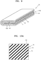
- FIG. 9 is a perspective view of an embodiment of a metal-air battery 1C.
- FIG. 10A is a plan view of an embodiment of a gas diffusion layer 14
- FIG. 10B is a plan view of an embodiment of a gas diffusion layer 14C
- FIG. 10C is a plan view of an embodiment of a gas diffusion layer 14E.
- the metal-air battery 1C may include the negative electrode metal layer 11, the electrolyte layer 12, the positive electrode layer 13, and a gas diffusion layer 14D.
- the same component as that in the previous embodiments uses the same reference numeral, and a redundant description thereof will be omitted here.
- the metal-air battery 1C may have a three-dimensional (3D) shape.
- the negative electrode metal layer 11, the electrolyte layer 12, and the positive electrode layer 13 may be bent.
- the gas diffusion layer 14 may have a one-layer structure in which the plurality of carbon fibers 141 are arranged on the positive electrode layer 13. Respective portions of the carbon fibers 141 may be inserted into the insertion grooves 133 of the positive electrode layer 13.
- the gas diffusion layer 14 is bent along a bending line FL to thereby form the gas diffusion layer 14D of a structure in which both ends of the gas diffusion layer 14D face each other as shown in FIG. 9 .
- the bent gas diffusion layer 14D may have a two-layer structure.
- the gas diffusion layer 14C may include the first carbon fiber layer 140, on which the plurality of carbon fibers 141 are arranged on the positive electrode layer 13, and the second carbon fiber layer 150, on which the plurality of carbon fibers 151 are arranged on the first carbon fiber layer 140.
- the carbon fibers 141 of the first carbon fiber layer 140 may intersect with the carbon fibers 151 of the second carbon fiber layer 150.
- the gas diffusion layer 14C is bent along the bending line FL to thereby form the gas diffusion layer 14D of a structure in which both ends of the gas diffusion layer 14D face each other.
- the bent gas diffusion layer 14D may have a layer structure of four or less layers.
- the gas diffusion layer 14E may be disposed on a portion of the positive electrode layer 13.
- the negative electrode metal layer 11, the electrolyte layer 12, and the positive electrode layer 13 are bent over the gas diffusion layer 14E such that the positive electrode layer 13 contacts three surfaces of the gas diffusion layer 14E, and one surface of the gas diffusion layer 14E may be exposed.
- the gas diffusion layer 14E may have a layer structure of two or less layers.
- a structure in which a single gas diffusion layer 14D is included and the negative electrode metal layer 11, the electrolyte layer 12, and the positive electrode layer 13 are bent once has been illustrated as the metal-air battery 1C having a 3D shape.
- the metal-air battery 1C having a 3D shape is not limited thereto and may be variously modified.
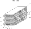
- a metal-air battery 1D may include a plurality of gas diffusion layers 14D, and may have a structure in which the negative electrode metal layer 11, the electrolyte layer 12, and the positive electrode layer 13 are bent multiple times.
- FIG. 11A a metal-air battery 1D may include a plurality of gas diffusion layers 14D, and may have a structure in which the negative electrode metal layer 11, the electrolyte layer 12, and the positive electrode layer 13 are bent multiple times.
- a metal-air battery 1E may have a structure in which a plurality of battery cells 10 are arranged vertically, each battery cell 10 has a single gas diffusion layer 14D, and the negative electrode metal layer 11, the electrolyte layer 12, and the positive electrode layer 13 are bent once for each battery cell 10.
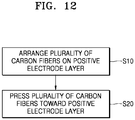
- FIG. 12 is a flowchart of a method of manufacturing the metal-air battery 1, according to an embodiment.
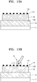
- FIGS. 13A and 13B are cross-sectional views of an embodiment of a method of manufacturing the metal-air battery 1.
- a plurality of carbon fibers 141 are arranged on the first surface 131 of the positive electrode layer 13, in operation S10.
- the plurality of carbon fibers 141 may be sprayed onto the first surface 131 of the positive electrode layer 13.
- the plurality of carbon fibers 141 may be arranged such that the average gap, e.g., distance, between adjacent carbon fibers of the plurality of carbon fibers 141 is about 30 ⁇ m to about 1,000 ⁇ m.
- Each of the plurality of carbon fibers 141 may include carbon as a main component, and have a diameter of less than or equal to about 20 ⁇ m.
- each carbon fiber 141 may have a diameter of about 5 ⁇ m to about 10 ⁇ m.
- the carbon fibers 141 may be referred to as graphite fibers.
- the carbon fibers 141 may be hollow carbon fibers.
- Each of the carbon fibers 141 may have a length of greater than or equal to about 3 mm.
- a length of the plurality of carbon fibers 141 may be less than or equal to about 1,000 mm.
- the length of each of the carbon fibers 141 may be determined based on a length of the positive electrode layer 13. For example, when the positive electrode layer 13 is long, long carbon fibers 141 may be used, and, when the positive electrode layer 13 is short, short carbon fibers 141 may be used.
- the plurality of carbon fibers 141 when the plurality of carbon fibers 141 are arranged on one surface of the positive electrode layer 13, the plurality of carbon fibers 141 are pressed toward the positive electrode layer 13, in operation S20. Due to the pressing, respective portions of the plurality of carbon fibers 141 may be inserted into the first surface 131 of the positive electrode layer 13. Accordingly, a plurality of insertion grooves 133 into which the respective portions of the carbon fibers 141 have been inserted may be formed on the positive electrode layer 13.
- the carbon fibers 141 arranged on one surface of the positive electrode layer 13 may be pressed by a rotatable roller R and thus may be stuck into the positive electrode layer 13.
- the plurality of carbon fibers 141 may be sequentially pressed by rotating and moving the roller R.
- the plurality of carbon fibers 141 of the gas diffusion layer 14 may be pressed such that the carbon fibers 141 are fixable to the positive electrode layer 13.
- the carbon fibers 141 may be pressed toward the positive electrode layer 13 such that the average depth of the insertion grooves 133 is about 20 % to about 60 % of the diameter of a carbon fiber of the plurality of carbon fibers 141 or each of the carbon fibers 141.
- the carbon fibers 141 may be pressed toward the positive electrode layer 13 such that the average width of the insertion grooves 133 is about 80 % to about 100 % of the diameter of a carbon fiber of the plurality of carbon fibers 141 or each of the carbon fibers 141.
- the plurality of carbon fibers 141 are arranged such that respective portions thereof are inserted into the positive electrode layer 13, and thus the gas diffusion layer 14 supported by one surface of the positive electrode layer 13 may be formed.
- the weight per unit area of the gas diffusion layer 14 may be minimized.
- the weight per unit area of the gas diffusion layer 14 may be less than or equal to about 0.5 mg/cm 2 .
- the weight per unit area of the gas diffusion layer 14 may be greater than or equal to about 0.007 mg/cm 2 .
- a method of fixing the gas diffusion layer 14 onto the positive electrode layer 13 has been described by focusing on the method of manufacturing the metal-air battery 1 having a 2D planar structure.
- the fixing method is not limited thereto, and may be applied to methods of manufacturing the metal-air batteries 1B, 1C, 1D, and 1E having various structures.
- the 3D metal-air batteries 1C, 1D, and 1E each having a bent structure may be manufactured by bending the gas diffusion layer 14 supported by the positive electrode layer 13 due to pressing of the plurality of carbon fibers 141, the positive electrode layer 13, the electrolyte layer 12, and the negative electrode metal layer 11.
- FIG. 14 is an electron microscope view of the positive electrode layer 13 manufactured in the method of manufacturing the metal-air battery 1.
- the insertion grooves 133 are formed in a surface of the positive electrode layer 13.
- the insertion grooves 133 may be distinguished from fine grooves generated during the manufacture of the positive electrode layer 13.
- a depth of each of the insertion groove 133 may be greater than or equal to about 1.4 ⁇ m. According to an embodiment, the depth of each of the insertion groove 133 may be greater than or equal to about 4 ⁇ m.
- Comparative Example 1 Manufacture of comparative lithium-air battery
- Carbon nanotubes, a PTFE binder, and a positive electrode electrolyte solution were weighed at a certain weight ratio, for example 1:0.2:2 and then mechanically kneaded, and a result of the kneading was manufactured to have a certain thickness, for example 30 urn by a roll press and then dried for two hours in an oven of 80°C, thereby manufacturing a rectangular positive electrode layer.
- a weight per unit area of the positive electrode layer was 2.7 milligrams per square centimeter (mg/cm 2 ).
- a separation layer was coated with a poly(diallyldimethylammonium-bis (trifluoromethanesulfonyl)imide) (“PIL”) solution including electrolyte, for example LiTFSI and then vacuum-dried (at 60°C and for 6 hours) such that a solvent is removed from the separation layer, to thereby obtaining a solid electrolyte layer.
- PIL poly(diallyldimethylammonium-bis (trifluoromethanesulfonyl)imide)
- electrolyte for example LiTFSI
- a weight per unit area of the electrolyte layer was 2.7 mg/cm 2 .
- the electrolyte layer was disposed on one surface of the positive electrode layer, and a lithium metal as a negative electrode metal layer was disposed on the surface of the electrolyte layer opposite to the positive electrode layer.
- Comparative Example 2 Manufacture of comparative lithium-air battery
- a lithium-air battery according to Comparative Example 2 was manufactured the same as the lithium-air battery according to Comparative Example 1, except that a gas diffusion layer was disposed within a bent positive electrode layer.
- the lithium-air battery according to Comparative Example 2 was manufactured by disposing a gas diffusion layer on a positive electrode layer and then bending the positive electrode layer, an electrolyte layer, and a negative electrode metal layer as shown in FIG. 9 such that the positive electrode layer surrounds at least three surfaces of the gas diffusion layer. At this time, a carbon paper having a weight per unit area of 4.2 mg/cm 2 was used as the gas diffusion layer.
- the positive electrode layer was manufactured using the same method as that used in Comparative Example 1.
- the electrolyte layer was manufactured using the same method as that used in Comparative Example 1.
- a plurality of carbon fibers (graphite fibers by Fibre Glast) having a length of 0.25 inches and a diameter of 7 ⁇ m are arranged on the positive electrode layer.
- the plurality of carbon fibers arranged on the positive electrode layer are pressed with a certain pressure.
- the plurality of carbon fibers are inserted into and fixed to insertion grooves of the positive electrode layer.
- the gas diffusion layer is fixed to the positive electrode layer without using binders, and has a weight per unit area of 0.2 mg/cm 2 .
- the lithium-air battery according to Embodiment 1 was manufactured by disposing the gas diffusion layer on the positive electrode layer and then bending the gas diffusion layer, the positive electrode layer, the electrolyte layer, and the negative electrode metal layer as shown in FIGS. 9 and 10A .
- the lithium-air battery according to Embodiment 2 was manufactured the same as the lithium-air battery according to Embodiment 1, except for a weight per unit area of a gas diffusion layer.
- the gas diffusion layer is fixed to a positive electrode layer without using binders, and has a weight per unit area of 0.05 mg/cm 2 .
- the lithium-air battery according to Embodiment 3 was manufactured the same as the lithium-air battery according to Embodiment 1, except for a weight per unit area of a gas diffusion layer.
- the gas diffusion layer is fixed to a positive electrode layer without using binders, and has a weight per unit area of 0.03 mg/cm 2 .
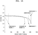
- Discharge capacities of the lithium-air batteries manufactured according to Embodiments 1 to 3 and Comparative Examples 1 to 2 were measured at 80°C under a 1 atmosphere (atm) oxygen atmosphere, and a result of the measurement was shown in Table 1 and FIG. 15 .
- each of the lithium-air batteries has a once-bent structure in which a positive electrode is disposed on an upper portion and a lower portion of a gas diffusion layer
- a weight per unit area of the gas diffusion layer according to Comparative Example 2 was calculated by respectively allocating halves of the weight per unit area to an upper positive electrode and a lower positive electrode.
- Table 1 Shape of gas diffusion layer Weight per unit area (mg/cm 2 ) Energy density (Wh/kg) Comparative Example 1 none 0 112 Comparative Example 2 Carbon paper 2.1 632 Embodiment 1 Carbon fibers (no binders) 0.2 744 Embodiment 2 Carbon fibers (no binders) 0.05 820 Embodiment 3 Carbon fibers (no binders) 0.03 827
- the lithium-air battery having a gas diffusion layer according to Comparative Example 2 has an increased energy density but has an increased weight per unit area of 2.1 mg/cm 2 due to the presence of the gas diffusion layer.
- the lithium-air battery according to Embodiment 1 uses carbon fibers without binders as a gas diffusion layer.
- the weight per unit area of the gas diffusion layer may be reduced to less than or equal to about 1/10 of the weight per unit area of the gas diffusion layer according to Comparative Example 2, and the energy density may be increased.
- the weight per unit area of the gas diffusion layer may be less than the weight per unit area of the gas diffusion layer of Embodiment 1 and the energy density may be greater than the energy density of Embodiment 1.
- a metal-air battery including the gas diffusion layer As described above, according to a gas diffusion layer for metal-air batteries, a metal-air battery including the gas diffusion layer, and a method of manufacturing the metal-air battery, according to an embodiment, respective portions of carbon fibers are inserted into and fixed to a positive electrode layer in order to include no binders. Therefore, the weight per unit area of the gas diffusion layer may be reduced, and accordingly, the energy density of the metal-air battery may be increased.
Abstract
Description
- The present disclosure relates to a metal-air battery including a gas diffusion layer, and a method of manufacturing the metal-air battery. More particularly, the present disclosure relates to a gas diffusion layer for metal-air batteries having an increased energy density, a metal-air battery including the gas diffusion layer, and a method of manufacturing the metal-air battery.
- Metal-air batteries include a negative electrode capable of absorbing/releasing ions and a positive electrode that uses oxygen from the air as an active material. In the metal-air batteries, reduction/oxidation of oxygen introduced from the outside occurs at the positive electrode, oxidation/reduction of a metal occurs at the negative electrode, and the chemical energy generated by these reactions is extracted as electrical energy. For example, the metal-air batteries absorb oxygen during discharging and release oxygen during charge. Since the metal-air batteries use oxygen from the atmosphere, the metal-air batteries may have dramatically-increased energy densities, compared to other types of secondary batteries. For example, the metal-air batteries may have an energy density that is several times greater than an energy density of lithium-ion batteries.
- Moreover, since there is a low possibility of ignition of the metal-air batteries at an abnormally high temperature, the metal-air batteries have excellent stability. Also, since the metal-air batteries operate only by storing/releasing oxygen and do not use a heavy metal, the risk of causing environmental pollution is low. Due to such various advantages, much research has been conducted on metal-air batteries.
- Provided are a gas diffusion layer for metal-air batteries with increased energy density by reducing a weight per unit area of the gas diffusion layer, a metal-air battery including the gas diffusion layer, and a method of manufacturing the metal-air battery.
- Additional aspects will be set forth in part in the description which follows and, in part, will be apparent from the description, or may be learned by practice of the presented embodiments.
- According to an aspect of an embodiment, a metal-air battery includes at least one positive electrode layer, which is configured for using oxygen as an active material and includes a first surface and a second surface opposite the first surface; a gas diffusion layer on the first surface of the positive electrode layer and including a plurality of carbon fibers; an electrolyte layer on the second surface of the positive electrode layer; and a negative electrode metal layer on the electrolyte layer, wherein the positive electrode layer includes a plurality of grooves and portions of the plurality of carbon fibers are in the grooves.
- An average depth of each of the plurality of grooves may be about 20 % to about 60 % of a diameter of each of the plurality of carbon fibers.
- An average width of each of the plurality of grooves may be about 80 % to about 100 % of a diameter of a carbon fiber of the plurality of carbon fibers.
- An average length of each of the plurality of grooves may be greater than or equal to about 3 millimeters
- An average distance between adjacent grooves of the plurality of grooves may be about 30 micrometers to about 1,000 micrometers.
- A diameter of each of the plurality of carbon fibers may be about 5 micrometers to about 10 micrometers.
- A weight per unit area of the gas diffusion layer may be less than or equal to about 0.5 milligrams per square centimeter.
- The weight per unit area of the gas diffusion layer may be greater than or equal to about 0.007 milligrams per square centimeter.
- The gas diffusion layer may include a first carbon fiber layer including a plurality of carbon fibers arranged on the positive electrode layer, and a second carbon fiber layer on the first carbon fiber layer and including a plurality of carbon fibers extending in a direction intersecting a direction in which each of the plurality of carbon fibers of the first carbon fiber layer extends.
- The gas diffusion layer may include a fold.
- The gas diffusion layer may include a plurality of carbon fiber layers including a plurality of carbon fibers, and the plurality of carbon fiber layers may include less than or equal to four layers.
- The gas diffusion layer may be partially on the positive electrode layer. The negative electrode metal layer, the electrolyte layer, and the positive electrode layer may be bent over the gas diffusion layer such that the positive electrode layer contacts three surfaces of the gas diffusion layer, and one surface of the gas diffusion layer may be exposed.
- According to an aspect of an embodiment, a method of manufacturing a metal-air battery includes: arranging a plurality of carbon fibers on a first surface of a positive electrode layer, which is configured for using oxygen as an active material; pressing the plurality of carbon fibers toward the positive electrode layer such that portions of the plurality of carbon fibers are inserted into the first surface of the positive electrode layer to form grooves, to thereby form a gas diffusion layer; and providing an electrolyte layer on a second surface of the positive electrode layer and a negative electrode metal layer on the electrolyte layer to form the metal-air battery.
- The pressing of the plurality of carbon fibers may include pressing the plurality of carbon fibers such that an average depth of the grooves is about 20 % to about 60 % of a diameter of a carbon fiber of the plurality of carbon fibers.
- The pressing of the plurality of carbon fibers may include pressing the plurality of carbon fibers such that an average width of the grooves is about 80 % to about 100 % of a diameter of a carbon fiber of the plurality of carbon fibers.
- The arranging of the plurality of carbon fibers may include arranging the plurality of carbon fibers such that an average distance between adjacent carbon fibers of the plurality of carbon fibers is about 30 micrometers to about 1,000 micrometers.
- A weight per unit area of the gas diffusion layer may be less than or equal to about 0.5 milligrams per square centimeter.
- The weight per unit area of the gas diffusion layer may be greater than or equal to about 0.007 milligrams per square centimeter.
- According to an aspect of an embodiment, a gas diffusion layer includes a plurality of carbon fibers arranged on a first surface of a positive electrode layer which is configured for using oxygen as an active material, wherein portions of the plurality of carbon fibers are in the first surface of the positive electrode layer.
- The gas diffusion layer may include no binders.
- The above and other advantages and features of this disclosure will become more apparent by describing in further detail exemplary embodiments thereof with reference to the accompanying drawings, in which:
-
FIG. 1 is a cross-sectional view of an embodiment of a metal-air battery; -
FIG. 2 is a magnified view of a portion of the gas diffusion layer ofFIG. 1 ; -
FIG. 3 is a cross-sectional view of the positive electrode layer ofFIG. 2 , in which the gas diffusion layer is omitted; -
FIG. 4A is a plan view of an embodiment of a gas diffusion layer, andFIG. 4B is a plan view of an embodiment of a gas diffusion layer; -
FIG. 5 is a graph showing a voltage loss (mV) versus a weight per unit area (mg/cm2) of the gas diffusion layer; -
FIG. 6 is a cross-sectional view of an embodiment of a metal-air battery; -
FIG. 7 is a magnified view of a portion of the gas diffusion layer ofFIG. 6 ; -
FIG. 8A is a plan view of an embodiment of a gas diffusion layer, andFIG. 8B is a plan view of an embodiment of a gas diffusion layer; -
FIG. 9 is a perspective view of an embodiment of a metal-air battery; -
FIG. 10A is a plan view of an embodiment of a gas diffusion layer,FIG. 10B is a plan view of an embodiment of a gas diffusion layer, andFIG. 10C is a plan view of an embodiment of a gas diffusion layer; -
FIGS. 11A and11B are perspective views of embodiments of metal-air batteries; -
FIG. 12 is a flowchart of an embodiment of a method of manufacturing a metal-air battery; -
FIGS. 13A and 13B are cross-sectional views of an embodiment of a method of manufacturing the metal-air battery; -
FIG. 14 is an electron microscope view of an embodiment of a positive electrode layer manufactured in the method of manufacturing the metal-air battery; and -
FIG. 15 is a graph showing voltage (V) versus energy density (Wh/kg) of metal-air batteries according to Comparative Examples 1 and 2 andEmbodiments - A gas diffusion layer for metal-air batteries, a metal-air battery, and a method of manufacturing the metal-air battery, according to an embodiment, will now be described in detail with reference to the accompanying drawings. Like reference numerals in the drawings denote like elements, and, in the drawings, the sizes or thicknesses of elements may be exaggerated for convenience of explanation. In this regard, embodiments below may have different forms and should not be construed as being limited to the descriptions set forth herein.
- It will be understood that when an element is referred to as being "on" another element, it can be directly on the other element or intervening elements may be present therebetween. In contrast, when an element is referred to as being "directly on" another element, there are no intervening elements present.
- It will be understood that, although the terms "first," "second," "third" etc. may be used herein to describe various elements, components, regions, layers and/or sections, these elements, components, regions, layers and/or sections should not be limited by these terms. These terms are only used to distinguish one element, component, region, layer or section from another element, component, region, layer or section. Thus, "a first element," "component," "region," "layer" or "section" discussed below could be termed a second element, component, region, layer or section without departing from the teachings herein.
- The terminology used herein is for the purpose of describing particular embodiments only and is not intended to be limiting. As used herein, the singular forms "a," "an," and "the" are intended to include the plural forms, including "at least one," unless the content clearly indicates otherwise. "At least one" is not to be construed as limiting "a" or "an." "Or" means "and/or." As used herein, the term "and/or" includes any and all combinations of one or more of the associated listed items. It will be further understood that the terms "comprises" and/or "comprising," or "includes" and/or "including" when used in this specification, specify the presence of stated features, regions, integers, steps, operations, elements, and/or components, but do not preclude the presence or addition of one or more other features, regions, integers, steps, operations, elements, components, and/or groups thereof.
- Furthermore, relative terms, such as "lower" or "bottom" and "upper" or "top," may be used herein to describe one element's relationship to another element as illustrated in the Figures. It will be understood that relative terms are intended to encompass different orientations of the device in addition to the orientation depicted in the Figures. For example, if the device in one of the figures is turned over, elements described as being on the "lower" side of other elements would then be oriented on "upper" sides of the other elements. The exemplary term "lower," can therefore, encompasses both an orientation of "lower" and "upper," depending on the particular orientation of the figure. Similarly, if the device in one of the figures is turned over, elements described as "below" or "beneath" other elements would then be oriented "above" the other elements. The exemplary terms "below" or "beneath" can, therefore, encompass both an orientation of above and below.
- "About" or "approximately" as used herein is inclusive of the stated value and means within an acceptable range of deviation for the particular value as determined by one of ordinary skill in the art, considering the measurement in question and the error associated with measurement of the particular quantity (i.e., the limitations of the measurement system). For example, "about" can mean within one or more standard deviations, or within ± 30%, 20%, 10% or 5% of the stated value.
- Unless otherwise defined, all terms (including technical and scientific terms) used herein have the same meaning as commonly understood by one of ordinary skill in the art to which this disclosure belongs. It will be further understood that terms, such as those defined in commonly used dictionaries, should be interpreted as having a meaning that is consistent with their meaning in the context of the relevant art and the present disclosure, and will not be interpreted in an idealized or overly formal sense unless expressly so defined herein.
- Exemplary embodiments are described herein with reference to cross section illustrations that are schematic illustrations of idealized embodiments. As such, variations from the shapes of the illustrations as a result, for example, of manufacturing techniques and/or tolerances, are to be expected. Thus, embodiments described herein should not be construed as limited to the particular shapes of regions as illustrated herein but are to include deviations in shapes that result, for example, from manufacturing. For example, a region illustrated or described as flat may, typically, have rough and/or nonlinear features. Moreover, sharp angles that are illustrated may be rounded. Thus, the regions illustrated in the figures are schematic in nature and their shapes are not intended to illustrate the precise shape of a region and are not intended to limit the scope of the present claims.
-
FIG. 1 is a cross-sectional view of an embodiment of a metal-air battery 1.FIG. 2 is a magnified view of a portion of thegas diffusion layer 14 ofFIG. 1 .FIG. 3 is a cross-sectional view of thepositive electrode layer 13 ofFIG. 2 , not including thegas diffusion layer 14.FIG. 4A is a plan view of an embodiment of agas diffusion layer 14, andFIG. 4B is a plan view of an embodiment of agas diffusion layer 14A. - Referring to
FIG. 1 , the metal-air battery 1 may have a two-dimensional ("2D") planar structure. For example, the metal-air battery 1 may be obtained by sequentially depositing a negativeelectrode metal layer 11, anelectrolyte layer 12, apositive electrode layer 13, and thegas diffusion layer 14 for metal-air batteries (hereinafter, referred to as the gas diffusion layer 14). The metal-air battery 1 may further include an outer casing (not shown) that surrounds a portion of the metal-air battery 1 except for an upper surface of thegas diffusion layer 14. - The negative
electrode metal layer 11 functions to absorb/release metal ions, and may include, for example, lithium (Li), sodium (Na), zinc (Zn), potassium (K), calcium (Ca), magnesium (Mg), iron (Fe), aluminum (Al), an alloy thereof, or a combination thereof. - The
electrolyte layer 12 functions to transmit metal ions to thepositive electrode layer 13. Theelectrolyte layer 12 may be referred to as a negative electrode electrolyte layer. To this end, theelectrolyte layer 12 may include an electrolyte that is formed by dissolving a metal salt in a solvent. The electrolyte may be typically in a solid phase including a polymer-based electrolyte, an inorganic electrolyte, or a composite electrolyte obtained by mixing the polymer-based electrolyte with the inorganic electrolyte. - The
electrolyte layer 12 may be prepared in a bent form. For example, the metal salt may be a lithium salt such as LiN(SO2C2F5)2, LiClO4, LiBF4, LiPF6, LiSbF6, LiAsF6, LiCF3SO3, LiN(SO2CF3)2, LiC(SO2CF3)3, LiN(SO3CF3)2, LiC4F9SO3, LiAlCl4, lithium bis(trifluoromethanesulfonyl)imide ("LiTFSI"), or a combination thereof. - Another metal salt, such as AlCl3, MgCl2, NaCl, KCl, NaBr, KBr, CaCl2, or a combination thereof may be added to the lithium salt. The solvent may be any material as long as it may dissolve the lithium salt and the another metal salt.
- The
electrolyte layer 12 may further include a separation layer that prevents transmission of oxygen and has conductivity with respect to the metal ions. The separation layer may be a polymer-based separation film that may be bent. For example, the separation layer may be formed of a polymer nonwoven fabric, such as a nonwoven fabric of polypropylene or a nonwoven fabric of polyphenylene sulfide, or a porous film of olefin-based resin, such as polyethylene or polypropylene. The separation layer and the electrolyte may be formed as separate layers, or theelectrolytic layer 12 may be formed as one layer by impregnating pores of a porous separation layer with an electrolyte. For example, theelectrolytic layer 12 may be formed by impregnating the pores of a porous separation layer with an electrolyte formed by mixing polyethylene oxide ("PEO") with LiTFSI. - The
positive electrode layer 13 may include an electrolyte for conducting the metal ions, a catalyst for oxidizing/reducing oxygen, a conductive material, and a binder. For example, thepositive electrode layer 13 may be formed by preparing a positive electrode slurry by mixing the electrolyte, the catalyst, the conductive material, and the binder, adding a solvent, for example, propylene glycol thereto, and coating and drying the positive electrode slurry on theelectrolytic layer 12. - The electrolyte may include the lithium salt or the another metal salt. For example, the conductive material may be a porous carbon-based material, a conductive metal material, a conductive organic material, or a combination thereof. For example, the carbon-based material may be carbon black, graphite, graphene, activated carbon, carbon fiber, carbon nanotubes, or a combination thereof. For example, the conductive metal material may be used in the form of metal powder. For example, the catalyst may be platinum (Pt), gold (Au), silver (Ag), or a combination thereof, or may be an oxide of manganese (Mn), nickel (Ni), cobalt (Co), or a combination thereof. The binder may be, for example, polytetrafluoroethylene ("PTFE"), polypropylene, polyvinylidene fluoride ("PVDF"), polyethylene, styrene-butadiene rubber, or a combination thereof.
- The
positive electrode layer 13 has afirst surface 131 and asecond surface 132 opposite thefirst surface 131. Thegas diffusion layer 14 is disposed on thefirst surface 131 of thepositive electrode layer 13, and theelectrolyte layer 12 is disposed on thesecond surface 132. - The
gas diffusion layer 14 functions to absorb oxygen from the atmosphere and supply the oxygen to thepositive electrode layer 13. To this end, thegas diffusion layer 14 may have a structure for moving and diffusing external oxygen, e.g., smoothly moving and diffusing external oxygen. For example, thegas diffusion layer 14 may have a flow path structure. - The
gas diffusion layer 14 may have conductivity. For example, the first thin film layer may include a plurality ofcarbon fibers 141. Each of the plurality ofcarbon fibers 141 may include carbon as a main component and have a diameter of less than or equal to about 20 micrometers (µm). For example, each of thecarbon fibers 141 may have a diameter of about 5 µm to about 10 µm. - The
carbon fibers 141 may be referred to as graphite fibers. Thecarbon fibers 141 may be hollow carbon fibers. - Each of the
carbon fibers 141 may have a length of greater than or equal to about 3 millimeters (mm). A length of the plurality ofcarbon fibers 141 may be less than or equal to about 1,000 mm. - The length of each of the
carbon fibers 141 may be determined based on a length of thepositive electrode layer 13 on which thegas diffusion layer 14 is disposed. For example, when thepositive electrode layer 13 is long,long carbon fibers 141 may be used, and, when thepositive electrode layer 13 is short,short carbon fibers 141 may be used. - A weight of the
gas diffusion layer 14 may be less than or equal to about 19 %, e.g., about 1 % to about 19%, of an overall weight of the metal-air battery 1. To this end, thegas diffusion layer 14 according to an embodiment may include no binders. Since thegas diffusion layer 14 includes no binders, a weight per unit area, of thegas diffusion layer 14 may be reduced. For example, the weight per unit area of thegas diffusion layer 14 may be less than or equal to about 0.5 milligrams per square centimeter (mg/cm2), e.g., about 0.007 mg/cm2 to about 0.5 mg/cm2. - As described above, because the
gas diffusion layer 14 of the present application includes no binders, when the plurality ofcarbon fibers 141 are arranged on thefirst surface 131 of thepositive electrode layer 13 without any special actions, the plurality ofcarbon fibers 141 may not be fixed to thepositive electrode layer 13 and may become scattered or move during the manufacture of thegas diffusion layer 14. - Considering this point, referring to
FIGS. 2 and 3 , in the metal-air battery 1 according to an embodiment, respective portions of the plurality ofcarbon fibers 141 may be inserted into thepositive electrode layer 13 such that the plurality ofcarbon fibers 141 may be fixed to thepositive electrode layer 13. Accordingly, thepositive electrode layer 13 may haveinsertion grooves 133 into which the respective portions of thecarbon fibers 141 are inserted. Due to this insertion of the respective portions of thecarbon fibers 141 of thegas diffusion layer 14 into theinsertion grooves 133 of thepositive electrode layer 13, thegas diffusion layer 14 may be fixed to thepositive electrode layer 13. - The
insertion grooves 133 of thepositive electrode layer 13 may have depths, widths, lengths, and gaps that enable thecarbon fibers 141 of thegas diffusion layer 14 to be fixed to thepositive electrode layer 13 and also enable oxygen to be sufficiently supplied and diffused. - For example, an average depth d of the
insertion grooves 133 may be about 20 % to about 60 % of a diameter of a carbon fiber of the plurality ofcarbon fibers 141 or each of thecarbon fibers 141. When each of thecarbon fibers 141 has a diameter of about 7 µm, each of theinsertion grooves 133 may have an average depth d of greater than or equal to about 1.4 µm. - For example, an average width w of the
insertion grooves 133 may be about 80 % to about 100 % of the diameter of a carbon fiber of the plurality ofcarbon fibers 141 or each of thecarbon fibers 141. An average length of each of theinsertion grooves 133 may be greater than or equal to about 3 mm. An average gap g between adjacent insertion grooves of the plurality ofinsertion grooves 133 may be about 30 µm to about 1,000 µm. Thegas diffusion layer 14 may include a first space occupied by thecarbon fibers 141, and a second space in which nocarbon fibers 141 are arranged and oxygen gas is movable and diffusible. A ratio of the second space to thegas diffusion layer 14 may be about 80 % to about 99 %. - The
gas diffusion layer 14 may have a single layer structure. For example, the plurality ofcarbon fibers 141 may be arranged on thepositive electrode layer 13 to form a single layer. - Referring to
FIG. 4A , the plurality ofcarbon fibers 141 extend in a uniform direction and may be spaced apart from each other. However, the arrangement of the plurality ofcarbon fibers 141 is not limited thereto, and the plurality ofcarbon fibers 141 may be arranged in various manners. For example, as shown inFIG. 4B , the plurality ofcarbon fibers 141 of thegas diffusion layer 14A extend in various directions and may be arranged to be at least partially spaced apart from each other. - As described above, even when the gas diffusion layers 14 and 14A include no binders, the plurality of
carbon fibers 141 are inserted into theinsertion grooves 133 of thepositive electrode layer 13 and fixed to thepositive electrode layer 13, and thus the weight per unit area may be reduced to less than or equal to about 0.5 mg/cm2, e.g., about 0.007 mg/cm2 to about 0.5 mg/cm2, and an energy density of the metal-air battery 1 may be increased. - However, when the weight per unit area of the
gas diffusion layer 14 becomes too small, a voltage loss due to a resistance in ohms may increase to the extent of affecting the efficiency of the metal-air battery 1. -
FIG. 5 is a graph showing a voltage loss versus a weight per unit area of thegas diffusion layer 14. Referring toFIG. 5 , when the weight per unit area of thegas diffusion layer 14 decreases to a certain value or less, the voltage loss increases sharply. Accordingly, considering this sharp increase in the voltage loss, thegas diffusion layer 14 according to an embodiment may have a weight per unit area of greater than or equal to about 0.007 mg/cm2 so that a voltage loss due to a resistance in ohms is less than or equal to about 1 millivolt (mV). -
FIG. 6 is a cross-sectional view of an embodiment of a metal-air battery 1B.FIG. 7 is a magnified view of a portion of thegas diffusion layer 14B ofFIG. 6 .FIG. 8A is a plan view of an embodiment of adiffusion layer 14B, andFIG. 8B is a plan view of an embodiment of agas diffusion layer 14C. - Referring to
FIGS. 6 and 7 , the metal-air battery 1B may include the negativeelectrode metal layer 11, theelectrolyte layer 12, thepositive electrode layer 13, and thegas diffusion layer 14B. The same component as that in the previous embodiments uses the same reference numeral, and a redundant description thereof will be omitted here. - The
gas diffusion layer 14B has a two-layer structure, and carbon fiber layers 140 and 150 may include a plurality ofcarbon fibers 141 and a plurality ofcarbon fibers 151, respectively. Each of the carbon fiber layers 140 and 150 include no binders. In thegas diffusion layer 14B having a two-layer structure, the plurality ofcarbon fibers gas diffusion layer 14B may include a firstcarbon fiber layer 140 in which respective portions of the plurality ofcarbon fibers 141 are inserted into theinsertion grooves 133 of thefirst surface 131, and a secondcarbon fiber layer 150 in which the plurality ofcarbon fibers 151 extend on the firstcarbon fiber layer 140 in a direction intersecting with a direction in which each of thecarbon fibers 141 of the firstcarbon fiber layer 140 extends. - For example, as shown in
FIG. 8A , thegas diffusion layer 14B may include the carbon fiber layers 140 and 150 of which the plurality ofcarbon fibers 141 and the plurality ofcarbon fibers 151 are arranged in respective uniform directions. As another example, as shown inFIG. 8B , thegas diffusion layer 14C may include carbon fiber layers 140 and 150 of which the plurality ofcarbon fibers - Although the
carbon fibers 151 of the secondcarbon fiber layer 150 are spaced apart from thepositive electrode layer 13 inFIG. 7 , embodiments are not limited thereto. For example, although not shown in the drawings, respective portions of thecarbon fibers 151 of the secondcarbon fiber layer 150 may be arranged on thecarbon fibers 141 of the firstcarbon fiber layer 140 and are thus not inserted into thepositive electrode layer 13, whereas other portions of thecarbon fibers 151 of the secondcarbon fiber layer 150 may be inserted into portions of thepositive electrode layer 13 that is exposed and between thecarbon fibers 141 of the firstcarbon fiber layer 140, e.g., portions of thepositive electrode layer 13 not covered by thecarbon fibers 141 of the firstcarbon fiber layer 140. - Each of the gas diffusion layers 14B and 14C may have a layer structure of two or less layers. If each of the gas diffusion layers 14B and 14C has a layer structure of three or more layers, because there are no binders for fixing the
carbon fibers carbon fibers positive electrode layer 13, and thus may not be fixed thereto. On the other hand, if each of the gas diffusion layers 14B and 14C has a layer structure of two or less layers, even when there are no binders for fixing thecarbon fibers carbon fibers positive electrode layer 13 and thus may be supported thereby. -
FIG. 9 is a perspective view of an embodiment of a metal-air battery 1C.FIG. 10A is a plan view of an embodiment of agas diffusion layer 14,FIG. 10B is a plan view of an embodiment of agas diffusion layer 14C, andFIG. 10C is a plan view of an embodiment of agas diffusion layer 14E. - Referring to
FIG. 9 , the metal-air battery 1C may include the negativeelectrode metal layer 11, theelectrolyte layer 12, thepositive electrode layer 13, and agas diffusion layer 14D. The same component as that in the previous embodiments uses the same reference numeral, and a redundant description thereof will be omitted here. - The metal-
air battery 1C may have a three-dimensional (3D) shape. In the metal-air battery 1C, the negativeelectrode metal layer 11, theelectrolyte layer 12, and thepositive electrode layer 13 may be bent. - For example, referring to
FIG. 10A , thegas diffusion layer 14 may have a one-layer structure in which the plurality ofcarbon fibers 141 are arranged on thepositive electrode layer 13. Respective portions of thecarbon fibers 141 may be inserted into theinsertion grooves 133 of thepositive electrode layer 13. Thegas diffusion layer 14 is bent along a bending line FL to thereby form thegas diffusion layer 14D of a structure in which both ends of thegas diffusion layer 14D face each other as shown inFIG. 9 . The bentgas diffusion layer 14D may have a two-layer structure. - As another example, referring to
FIG. 10B , thegas diffusion layer 14C may include the firstcarbon fiber layer 140, on which the plurality ofcarbon fibers 141 are arranged on thepositive electrode layer 13, and the secondcarbon fiber layer 150, on which the plurality ofcarbon fibers 151 are arranged on the firstcarbon fiber layer 140. Thecarbon fibers 141 of the firstcarbon fiber layer 140 may intersect with thecarbon fibers 151 of the secondcarbon fiber layer 150. Thegas diffusion layer 14C is bent along the bending line FL to thereby form thegas diffusion layer 14D of a structure in which both ends of thegas diffusion layer 14D face each other. The bentgas diffusion layer 14D may have a layer structure of four or less layers. - As another example, referring to
FIG. 10C , thegas diffusion layer 14E may be disposed on a portion of thepositive electrode layer 13. The negativeelectrode metal layer 11, theelectrolyte layer 12, and thepositive electrode layer 13 are bent over thegas diffusion layer 14E such that thepositive electrode layer 13 contacts three surfaces of thegas diffusion layer 14E, and one surface of thegas diffusion layer 14E may be exposed. Thegas diffusion layer 14E may have a layer structure of two or less layers. - In the above-described embodiments, a structure in which a single
gas diffusion layer 14D is included and the negativeelectrode metal layer 11, theelectrolyte layer 12, and thepositive electrode layer 13 are bent once has been illustrated as the metal-air battery 1C having a 3D shape. However, the metal-air battery 1C having a 3D shape is not limited thereto and may be variously modified. For example, as shown inFIG. 11A , a metal-air battery 1D may include a plurality of gas diffusion layers 14D, and may have a structure in which the negativeelectrode metal layer 11, theelectrolyte layer 12, and thepositive electrode layer 13 are bent multiple times. As another example, as shown inFIG. 11B , a metal-air battery 1E may have a structure in which a plurality ofbattery cells 10 are arranged vertically, eachbattery cell 10 has a singlegas diffusion layer 14D, and the negativeelectrode metal layer 11, theelectrolyte layer 12, and thepositive electrode layer 13 are bent once for eachbattery cell 10. -
FIG. 12 is a flowchart of a method of manufacturing the metal-air battery 1, according to an embodiment.FIGS. 13A and 13B are cross-sectional views of an embodiment of a method of manufacturing the metal-air battery 1. - Referring to
FIGS. 12 and13A , first, a plurality ofcarbon fibers 141 are arranged on thefirst surface 131 of thepositive electrode layer 13, in operation S10. The plurality ofcarbon fibers 141 may be sprayed onto thefirst surface 131 of thepositive electrode layer 13. The plurality ofcarbon fibers 141 may be arranged such that the average gap, e.g., distance, between adjacent carbon fibers of the plurality ofcarbon fibers 141 is about 30 µm to about 1,000 µm. - Each of the plurality of
carbon fibers 141 may include carbon as a main component, and have a diameter of less than or equal to about 20 µm. For example, eachcarbon fiber 141 may have a diameter of about 5 µm to about 10 µm. - The
carbon fibers 141 may be referred to as graphite fibers. Thecarbon fibers 141 may be hollow carbon fibers. - Each of the
carbon fibers 141 may have a length of greater than or equal to about 3 mm. A length of the plurality ofcarbon fibers 141 may be less than or equal to about 1,000 mm. - The length of each of the
carbon fibers 141 may be determined based on a length of thepositive electrode layer 13. For example, when thepositive electrode layer 13 is long,long carbon fibers 141 may be used, and, when thepositive electrode layer 13 is short,short carbon fibers 141 may be used. - Referring to
FIGS. 12 and13B , when the plurality ofcarbon fibers 141 are arranged on one surface of thepositive electrode layer 13, the plurality ofcarbon fibers 141 are pressed toward thepositive electrode layer 13, in operation S20. Due to the pressing, respective portions of the plurality ofcarbon fibers 141 may be inserted into thefirst surface 131 of thepositive electrode layer 13. Accordingly, a plurality ofinsertion grooves 133 into which the respective portions of thecarbon fibers 141 have been inserted may be formed on thepositive electrode layer 13. - For example, the
carbon fibers 141 arranged on one surface of thepositive electrode layer 13 may be pressed by a rotatable roller R and thus may be stuck into thepositive electrode layer 13. The plurality ofcarbon fibers 141 may be sequentially pressed by rotating and moving the roller R. - The plurality of
carbon fibers 141 of thegas diffusion layer 14 may be pressed such that thecarbon fibers 141 are fixable to thepositive electrode layer 13. - The
carbon fibers 141 may be pressed toward thepositive electrode layer 13 such that the average depth of theinsertion grooves 133 is about 20 % to about 60 % of the diameter of a carbon fiber of the plurality ofcarbon fibers 141 or each of thecarbon fibers 141. Thecarbon fibers 141 may be pressed toward thepositive electrode layer 13 such that the average width of theinsertion grooves 133 is about 80 % to about 100 % of the diameter of a carbon fiber of the plurality ofcarbon fibers 141 or each of thecarbon fibers 141. - As described above, the plurality of
carbon fibers 141 are arranged such that respective portions thereof are inserted into thepositive electrode layer 13, and thus thegas diffusion layer 14 supported by one surface of thepositive electrode layer 13 may be formed. - As such, because the
gas diffusion layer 14 includes theconductive carbon fibers 141 but uses, e.g., includes, no binders, the weight per unit area of thegas diffusion layer 14 may be minimized. For example, the weight per unit area of thegas diffusion layer 14 may be less than or equal to about 0.5 mg/cm2. However, considering the voltage loss due to a resistance in ohms, the weight per unit area of thegas diffusion layer 14 may be greater than or equal to about 0.007 mg/cm2. - In the above-described embodiment, a method of fixing the
gas diffusion layer 14 onto thepositive electrode layer 13 has been described by focusing on the method of manufacturing the metal-air battery 1 having a 2D planar structure. However, the fixing method is not limited thereto, and may be applied to methods of manufacturing the metal-air batteries air batteries gas diffusion layer 14 supported by thepositive electrode layer 13 due to pressing of the plurality ofcarbon fibers 141, thepositive electrode layer 13, theelectrolyte layer 12, and the negativeelectrode metal layer 11. -
FIG. 14 is an electron microscope view of thepositive electrode layer 13 manufactured in the method of manufacturing the metal-air battery 1. - Referring to
FIG. 14 , it may be seen that theinsertion grooves 133 are formed in a surface of thepositive electrode layer 13. Theinsertion grooves 133 may be distinguished from fine grooves generated during the manufacture of thepositive electrode layer 13. A depth of each of theinsertion groove 133 may be greater than or equal to about 1.4 µm. According to an embodiment, the depth of each of theinsertion groove 133 may be greater than or equal to about 4 µm. - The disclosed embodiment will be described in more detail via the embodiments described below and comparative examples. However, the embodiments below are intended to exemplify the present disclosure, and the scope of the present disclosure is not limited thereto.
- Carbon nanotubes, a PTFE binder, and a positive electrode electrolyte solution were weighed at a certain weight ratio, for example 1:0.2:2 and then mechanically kneaded, and a result of the kneading was manufactured to have a certain thickness, for example 30 urn by a roll press and then dried for two hours in an oven of 80°C, thereby manufacturing a rectangular positive electrode layer. A weight per unit area of the positive electrode layer was 2.7 milligrams per square centimeter (mg/cm2).
- A separation layer was coated with a poly(diallyldimethylammonium-bis (trifluoromethanesulfonyl)imide) ("PIL") solution including electrolyte, for example LiTFSI and then vacuum-dried (at 60°C and for 6 hours) such that a solvent is removed from the separation layer, to thereby obtaining a solid electrolyte layer. A weight per unit area of the electrolyte layer was 2.7 mg/cm2.
- The electrolyte layer was disposed on one surface of the positive electrode layer, and a lithium metal as a negative electrode metal layer was disposed on the surface of the electrolyte layer opposite to the positive electrode layer.
- No gas diffusion layers were disposed on the positive electrode layer, and, as shown in
FIG. 9 , the positive electrode layer, the electrolyte layer, and the negative electrode metal layer were bent to manufacture a lithium-air battery. - The manufactured lithium-air battery has a structure in which cells are respectively arranged on an upper portion and a lower portion with respect to a bent center portion. Because a single cell has a horizontal length of 3 centimeters (cm), a vertical length of 1 cm, and an area of 3 square centimeters (cm2), an overall cell area of the lithium-air battery is 6 cm2 (= 3 cm×1 cm×2).
- A lithium-air battery according to Comparative Example 2 was manufactured the same as the lithium-air battery according to Comparative Example 1, except that a gas diffusion layer was disposed within a bent positive electrode layer.
- The lithium-air battery according to Comparative Example 2 was manufactured by disposing a gas diffusion layer on a positive electrode layer and then bending the positive electrode layer, an electrolyte layer, and a negative electrode metal layer as shown in
FIG. 9 such that the positive electrode layer surrounds at least three surfaces of the gas diffusion layer. At this time, a carbon paper having a weight per unit area of 4.2 mg/cm2 was used as the gas diffusion layer. - The positive electrode layer was manufactured using the same method as that used in Comparative Example 1.
- The electrolyte layer was manufactured using the same method as that used in Comparative Example 1.
- A plurality of carbon fibers (graphite fibers by Fibre Glast) having a length of 0.25 inches and a diameter of 7 µm are arranged on the positive electrode layer.
- The plurality of carbon fibers arranged on the positive electrode layer are pressed with a certain pressure. Thus, the plurality of carbon fibers are inserted into and fixed to insertion grooves of the positive electrode layer.
- The gas diffusion layer is fixed to the positive electrode layer without using binders, and has a weight per unit area of 0.2 mg/cm2.
- The lithium-air battery according to
Embodiment 1 was manufactured by disposing the gas diffusion layer on the positive electrode layer and then bending the gas diffusion layer, the positive electrode layer, the electrolyte layer, and the negative electrode metal layer as shown inFIGS. 9 and 10A . - The lithium-air battery according to
Embodiment 2 was manufactured the same as the lithium-air battery according toEmbodiment 1, except for a weight per unit area of a gas diffusion layer. In the lithium-air battery according toEmbodiment 2, the gas diffusion layer is fixed to a positive electrode layer without using binders, and has a weight per unit area of 0.05 mg/cm2. - The lithium-air battery according to
Embodiment 3 was manufactured the same as the lithium-air battery according toEmbodiment 1, except for a weight per unit area of a gas diffusion layer. In the lithium-air battery according toEmbodiment 3, the gas diffusion layer is fixed to a positive electrode layer without using binders, and has a weight per unit area of 0.03 mg/cm2. - Discharge capacities of the lithium-air batteries manufactured according to
Embodiments 1 to 3 and Comparative Examples 1 to 2 were measured at 80°C under a 1 atmosphere (atm) oxygen atmosphere, and a result of the measurement was shown in Table 1 andFIG. 15 . - Because each of the lithium-air batteries has a once-bent structure in which a positive electrode is disposed on an upper portion and a lower portion of a gas diffusion layer, a weight per unit area of the gas diffusion layer according to Comparative Example 2 was calculated by respectively allocating halves of the weight per unit area to an upper positive electrode and a lower positive electrode.
Table 1 Shape of gas diffusion layer Weight per unit area (mg/cm2) Energy density (Wh/kg) Comparative Example 1 none 0 112 Comparative Example 2 Carbon paper 2.1 632 Embodiment 1Carbon fibers (no binders) 0.2 744 Embodiment 2Carbon fibers (no binders) 0.05 820 Embodiment 3Carbon fibers (no binders) 0.03 827 - As shown in Table 1, compared with the lithium-air battery having no gas diffusion layers according to Comparative Example 1, the lithium-air battery having a gas diffusion layer according to Comparative Example 2 has an increased energy density but has an increased weight per unit area of 2.1 mg/cm2 due to the presence of the gas diffusion layer.
- In contrast with the lithium-air battery according to Comparative Example 2, the lithium-air battery according to
Embodiment 1 uses carbon fibers without binders as a gas diffusion layer. Thus, the weight per unit area of the gas diffusion layer may be reduced to less than or equal to about 1/10 of the weight per unit area of the gas diffusion layer according to Comparative Example 2, and the energy density may be increased. - Moreover, in the lithium-air batteries according to
Embodiments Embodiment 1 and the energy density may be greater than the energy density ofEmbodiment 1. - As described above, according to a gas diffusion layer for metal-air batteries, a metal-air battery including the gas diffusion layer, and a method of manufacturing the metal-air battery, according to an embodiment, respective portions of carbon fibers are inserted into and fixed to a positive electrode layer in order to include no binders. Therefore, the weight per unit area of the gas diffusion layer may be reduced, and accordingly, the energy density of the metal-air battery may be increased.
- While the present invention has been particularly shown and described with reference to the example embodiments thereof, it will be understood by those of ordinary skill in the art that various changes in form and details may be made therein. Therefore, the scope of the present disclosure should be determined by the accompanying claims.
Claims (15)
- A metal-air battery comprising:at least one positive electrode layer, which is configured for using oxygen as an active material and comprises a first surface and a second surface opposite the first surface;a gas diffusion layer on the first surface of the positive electrode layer and comprising a plurality of carbon fibers;an electrolyte layer on the second surface of the positive electrode layer; anda negative electrode metal layer on the electrolyte layer,wherein the positive electrode layer comprises a plurality of grooves, andwherein portions of the plurality of carbon fibers are in the grooves.
- The metal-air battery of claim 1, wherein an average depth of the plurality of grooves is 20 % to 60 % of a diameter of a carbon fiber of the plurality of carbon fibers.
- The metal-air battery of claim 1 or 2, wherein an average width of the plurality of grooves is 80 % to 100 % of a diameter of a carbon fiber of the plurality of carbon fibers.
- The metal-air battery of any preceding claim, wherein an average length of each of the plurality of grooves is greater than or equal to 3 millimeters.
- The metal-air battery of any preceding claim, wherein an average distance between adjacent grooves of the plurality of grooves is 30 micrometers to 1,000 micrometers.
- The metal-air battery of any preceding claim, wherein a diameter of each of the plurality of carbon fibers is 5 micrometers to 10 micrometers.
- The metal-air battery of any preceding claim, wherein a weight per unit area of the gas diffusion layer is less than or equal to 0.5 milligrams per square centimeter.
- The metal-air battery of claim 7, wherein the weight per unit area of the gas diffusion layer is greater than or equal to 0.007 milligrams per square centimeter.
- The metal-air battery of any preceding claim, wherein the gas diffusion layer comprises:a first carbon fiber layer comprising a plurality of carbon fibers arranged on the positive electrode layer, anda second carbon fiber layer on the first carbon fiber layer and comprising a plurality of carbon fibers extending in a direction intersecting a direction in which each of the plurality of carbon fibers of the first carbon fiber layer extends.
- The metal-air battery of any preceding claim, wherein the gas diffusion comprises a fold, and optionally wherein the gas diffusion layer comprises a plurality of carbon fiber layers comprising a plurality of carbon fibers, and the plurality of carbon fiber layers comprises less than or equal to four layers.
- The metal-air battery of any preceding claim, wherein
the gas diffusion layer is partially on the positive electrode layer, and
the negative electrode metal layer, the electrolyte layer, and the positive electrode layer are bent over the gas diffusion layer such that the positive electrode layer contacts at least three surfaces of the gas diffusion layer, and a first surface of the gas diffusion layer is exposed. - A method of manufacturing a metal-air battery, the method comprising:arranging a plurality of carbon fibers on a first surface of a positive electrode layer, which is configured for using oxygen as an active material;pressing the plurality of carbon fibers toward the positive electrode layer such that portions of the plurality of carbon fibers are inserted into the first surface of the positive electrode layer to form grooves, to thereby form a gas diffusion layer; andproviding an electrolyte layer on a second surface of the positive electrode layer and a negative electrode metal layer on the electrolyte layer to form the metal-air battery.
- The method of claim 12, wherein the pressing of the plurality of carbon fibers comprises pressing the plurality of carbon fibers such that an average depth of the grooves is 20 % to 60 % of a diameter of a carbon fiber of the plurality of carbon fibers.
- The method of claim 12 or 13, wherein the pressing of the plurality of carbon fibers comprises pressing the plurality of carbon fibers such that an average width of the grooves is 80 % to 100 % of a diameter of a carbon fiber of the plurality of carbon fibers.
- The method of claim 12, 13 or 14, wherein the arranging of the plurality of carbon fibers comprises arranging the plurality of carbon fibers such that an average distance between adjacent carbon fibers of the plurality of carbon fibers is 30 micrometers to 1,000 micrometers.
Applications Claiming Priority (1)
| Application Number | Priority Date | Filing Date | Title |
|---|---|---|---|
| KR1020170094966A KR102452946B1 (en) | 2017-07-26 | 2017-07-26 | Gas diffusion layer for metal air battery, metal air battery and method of manufacturing the same |
Publications (2)
| Publication Number | Publication Date |
|---|---|
| EP3435458A1 true EP3435458A1 (en) | 2019-01-30 |
| EP3435458B1 EP3435458B1 (en) | 2023-12-13 |
Family
ID=62563070
Family Applications (1)
| Application Number | Title | Priority Date | Filing Date |
|---|---|---|---|
| EP18176472.1A Active EP3435458B1 (en) | 2017-07-26 | 2018-06-07 | Metal-air battery including a gas diffusion layer, and method of manufacturing the metal-air battery |
Country Status (4)
| Country | Link |
|---|---|
| US (1) | US10707495B2 (en) |
| EP (1) | EP3435458B1 (en) |
| KR (1) | KR102452946B1 (en) |
| CN (1) | CN109309271B (en) |
Families Citing this family (6)
| Publication number | Priority date | Publication date | Assignee | Title |
|---|---|---|---|---|
| KR102526758B1 (en) | 2018-01-09 | 2023-04-27 | 삼성전자주식회사 | Composite membrane, Anode structure including composite membrane, Lithium battery including anode structure and Preparation method of composite membrane |
| KR20210155878A (en) * | 2020-06-17 | 2021-12-24 | 현대자동차주식회사 | Cathode Material of Lithium Air Battery and Cathode Manufacturing Method Using the Same |
| CN116210128A (en) | 2020-07-29 | 2023-06-02 | 伊顿智能动力有限公司 | Connector system including an interlock system |
| CN115917885A (en) | 2020-08-21 | 2023-04-04 | 伊顿智能动力有限公司 | Electrical connector system with high ampacity |
| WO2023147074A1 (en) * | 2022-01-28 | 2023-08-03 | Form Energy, Inc. | Bifacial sealed gas diffusion electrode |
| CN114953635B (en) * | 2022-05-30 | 2023-09-15 | 安徽天富环保科技材料有限公司 | Activated carbon fiber cloth for gas diffusion of new energy battery |
Citations (4)
| Publication number | Priority date | Publication date | Assignee | Title |
|---|---|---|---|---|
| EP2278655A1 (en) * | 2009-03-06 | 2011-01-26 | Toyota Jidosha Kabushiki Kaisha | Air electrode and non-aqueous air battery |
| US20160336602A1 (en) * | 2015-05-15 | 2016-11-17 | Samsung Electronics Co., Ltd. | Metal air battery and gas diffusion layer thereof |
| US20170054189A1 (en) * | 2015-08-17 | 2017-02-23 | Samsung Electronics Co., Ltd. | Metal air battery and gas diffusion layer equipped therein |
| EP3316366A1 (en) * | 2016-01-20 | 2018-05-02 | LG Chem, Ltd. | Positive electrode of lithium-air battery having side reaction prevention film to which metal catalyst is partially introduced, lithium-air battery having same, and manufacturing method therefor |
Family Cites Families (15)
| Publication number | Priority date | Publication date | Assignee | Title |
|---|---|---|---|---|
| US6500319B2 (en) * | 2001-04-05 | 2002-12-31 | Giner Electrochemical Systems, Llc | Proton exchange membrane (PEM) electrochemical cell having an integral, electrically-conductive, compression pad |
| US8182659B2 (en) * | 2001-04-05 | 2012-05-22 | Giner Electrochemical Systems, Llc | Proton exchange membrane (PEM) electrochemical cell having an integral, electrically-conductive, resiliently compressible, porous pad |
| WO2009014726A1 (en) | 2007-07-26 | 2009-01-29 | The Regents Of The University Of California | Methods for enhancing bacterial cell display of proteins and peptides |
| KR100920115B1 (en) | 2007-11-08 | 2009-10-01 | 금오공과대학교 산학협력단 | Gas diffusion layer coated with HTTS and method thereof |
| JP2011096492A (en) * | 2009-10-29 | 2011-05-12 | Sony Corp | Lithium air battery |
| US20110253699A1 (en) * | 2010-04-16 | 2011-10-20 | Morin Philip K | Portable food warmer with carbon fiber heating element |
| US8274019B2 (en) * | 2010-04-16 | 2012-09-25 | Carbon Fibers Heating Technologies, LLC | High temperature connector and method for manufacturing |
| US10047446B2 (en) * | 2010-07-04 | 2018-08-14 | Dioxide Materials, Inc. | Method and system for electrochemical production of formic acid from carbon dioxide |
| JP5421227B2 (en) * | 2010-07-05 | 2014-02-19 | 株式会社日本自動車部品総合研究所 | Manufacturing method, manufacturing apparatus and fuel cell for gas diffusion layer of fuel cell |
| KR101851317B1 (en) | 2011-07-26 | 2018-05-31 | 삼성전자주식회사 | porous carbonaceous composite material, cathode and lithium air battery comprsing the material, and preparation method thereof |
| US8979574B2 (en) | 2012-08-15 | 2015-03-17 | Tyco Electronics Corporation | Modular plug |
| US8714994B2 (en) | 2012-08-15 | 2014-05-06 | Tyco Electronics Corporation | Modular plug for power applications |
| CA2888706C (en) | 2012-12-05 | 2021-03-16 | Toray Industries, Inc. | Carbon-fiber nonwoven cloth and composite, uses and method of manufacturing thereof |
| KR101646397B1 (en) | 2014-12-03 | 2016-08-05 | 현대자동차주식회사 | A method for producing a anode of a lithium-air battery |
| KR20170020162A (en) | 2015-08-14 | 2017-02-22 | 주식회사 엘지화학 | Lithium air battery and method for manufactureing the same |
-
2017
- 2017-07-26 KR KR1020170094966A patent/KR102452946B1/en active IP Right Grant
-
2018
- 2018-04-09 US US15/947,997 patent/US10707495B2/en active Active
- 2018-04-11 CN CN201810319729.3A patent/CN109309271B/en active Active
- 2018-06-07 EP EP18176472.1A patent/EP3435458B1/en active Active
Patent Citations (4)
| Publication number | Priority date | Publication date | Assignee | Title |
|---|---|---|---|---|
| EP2278655A1 (en) * | 2009-03-06 | 2011-01-26 | Toyota Jidosha Kabushiki Kaisha | Air electrode and non-aqueous air battery |
| US20160336602A1 (en) * | 2015-05-15 | 2016-11-17 | Samsung Electronics Co., Ltd. | Metal air battery and gas diffusion layer thereof |
| US20170054189A1 (en) * | 2015-08-17 | 2017-02-23 | Samsung Electronics Co., Ltd. | Metal air battery and gas diffusion layer equipped therein |
| EP3316366A1 (en) * | 2016-01-20 | 2018-05-02 | LG Chem, Ltd. | Positive electrode of lithium-air battery having side reaction prevention film to which metal catalyst is partially introduced, lithium-air battery having same, and manufacturing method therefor |
Also Published As
| Publication number | Publication date |
|---|---|
| CN109309271B (en) | 2024-03-12 |
| KR102452946B1 (en) | 2022-10-11 |
| US20190036127A1 (en) | 2019-01-31 |
| KR20190012064A (en) | 2019-02-08 |
| CN109309271A (en) | 2019-02-05 |
| EP3435458B1 (en) | 2023-12-13 |
| US10707495B2 (en) | 2020-07-07 |
Similar Documents
| Publication | Publication Date | Title |
|---|---|---|
| EP3435458B1 (en) | Metal-air battery including a gas diffusion layer, and method of manufacturing the metal-air battery | |
| KR102654869B1 (en) | Composite electrolyte film, Electrochemical cell comprising composite electrolyte film and Preparation method of composite electrolyte film | |
| KR101249133B1 (en) | Bipolar device | |
| KR102420022B1 (en) | Cathode for metal-air battery and metal-air battery including the same | |
| EP3157084B1 (en) | Composite cathode, cathode-membrane assembly, electrochemical cell including the cathode-membrane assembly, and method of preparing the cathode-membrane assembly | |
| DE102014116162A1 (en) | Multifunctional battery separator | |
| US20190252688A1 (en) | Positive electrode for air battery | |
| US9972876B2 (en) | Metal air battery and gas diffusion layer equipped therein | |
| US9786932B2 (en) | Metal-air battery | |
| US10020552B2 (en) | Metal air battery and cathode current collector included therein | |
| US10263306B2 (en) | Metal air battery and gas diffusion layer thereof | |
| US20180301777A1 (en) | Metal-air battery including cathode with air path | |
| KR102452954B1 (en) | Cathode for metal-air battery and metal-air battery including the same | |
| EP3712996A1 (en) | Air battery positive electrode and air battery |
Legal Events
| Date | Code | Title | Description |
|---|---|---|---|
| PUAI | Public reference made under article 153(3) epc to a published international application that has entered the european phase |
Free format text: ORIGINAL CODE: 0009012 |
|
| STAA | Information on the status of an ep patent application or granted ep patent |
Free format text: STATUS: THE APPLICATION HAS BEEN PUBLISHED |
|
| AK | Designated contracting states |
Kind code of ref document: A1 Designated state(s): AL AT BE BG CH CY CZ DE DK EE ES FI FR GB GR HR HU IE IS IT LI LT LU LV MC MK MT NL NO PL PT RO RS SE SI SK SM TR |
|
| AX | Request for extension of the european patent |
Extension state: BA ME |
|
| STAA | Information on the status of an ep patent application or granted ep patent |
Free format text: STATUS: REQUEST FOR EXAMINATION WAS MADE |
|
| 17P | Request for examination filed |
Effective date: 20190730 |
|
| RBV | Designated contracting states (corrected) |
Designated state(s): AL AT BE BG CH CY CZ DE DK EE ES FI FR GB GR HR HU IE IS IT LI LT LU LV MC MK MT NL NO PL PT RO RS SE SI SK SM TR |
|
| STAA | Information on the status of an ep patent application or granted ep patent |
Free format text: STATUS: EXAMINATION IS IN PROGRESS |
|
| 17Q | First examination report despatched |
Effective date: 20230222 |
|
| GRAP | Despatch of communication of intention to grant a patent |
Free format text: ORIGINAL CODE: EPIDOSNIGR1 |
|
| STAA | Information on the status of an ep patent application or granted ep patent |
Free format text: STATUS: GRANT OF PATENT IS INTENDED |
|
| P01 | Opt-out of the competence of the unified patent court (upc) registered |
Effective date: 20230520 |
|
| INTG | Intention to grant announced |
Effective date: 20230626 |
|
| GRAS | Grant fee paid |
Free format text: ORIGINAL CODE: EPIDOSNIGR3 |
|
| GRAA | (expected) grant |
Free format text: ORIGINAL CODE: 0009210 |
|
| STAA | Information on the status of an ep patent application or granted ep patent |
Free format text: STATUS: THE PATENT HAS BEEN GRANTED |
|
| AK | Designated contracting states |
Kind code of ref document: B1 Designated state(s): AL AT BE BG CH CY CZ DE DK EE ES FI FR GB GR HR HU IE IS IT LI LT LU LV MC MK MT NL NO PL PT RO RS SE SI SK SM TR |
|
| REG | Reference to a national code |
Ref country code: GB Ref legal event code: FG4D |
|
| REG | Reference to a national code |
Ref country code: CH Ref legal event code: EP |
|
| REG | Reference to a national code |
Ref country code: DE Ref legal event code: R096 Ref document number: 602018062487 Country of ref document: DE |
|
| REG | Reference to a national code |
Ref country code: IE Ref legal event code: FG4D |
|
| PG25 | Lapsed in a contracting state [announced via postgrant information from national office to epo] |
Ref country code: GR Free format text: LAPSE BECAUSE OF FAILURE TO SUBMIT A TRANSLATION OF THE DESCRIPTION OR TO PAY THE FEE WITHIN THE PRESCRIBED TIME-LIMIT Effective date: 20240314 |
|
| REG | Reference to a national code |
Ref country code: LT Ref legal event code: MG9D |
|
| PG25 | Lapsed in a contracting state [announced via postgrant information from national office to epo] |
Ref country code: LT Free format text: LAPSE BECAUSE OF FAILURE TO SUBMIT A TRANSLATION OF THE DESCRIPTION OR TO PAY THE FEE WITHIN THE PRESCRIBED TIME-LIMIT Effective date: 20231213 |