EP3315922A1 - Appareil de dosage de liquides - Google Patents
Appareil de dosage de liquides Download PDFInfo
- Publication number
- EP3315922A1 EP3315922A1 EP16195522.4A EP16195522A EP3315922A1 EP 3315922 A1 EP3315922 A1 EP 3315922A1 EP 16195522 A EP16195522 A EP 16195522A EP 3315922 A1 EP3315922 A1 EP 3315922A1
- Authority
- EP
- European Patent Office
- Prior art keywords
- dosing
- dosing chamber
- liquid
- container
- sidewalls
- Prior art date
- Legal status (The legal status is an assumption and is not a legal conclusion. Google has not performed a legal analysis and makes no representation as to the accuracy of the status listed.)
- Granted
Links
- 239000007788 liquid Substances 0.000 title claims abstract description 105
- 239000000203 mixture Substances 0.000 claims description 38
- 230000000903 blocking effect Effects 0.000 claims description 20
- 238000004140 cleaning Methods 0.000 claims description 12
- 239000000758 substrate Substances 0.000 claims description 2
- 230000008901 benefit Effects 0.000 description 16
- 239000003599 detergent Substances 0.000 description 9
- XLYOFNOQVPJJNP-UHFFFAOYSA-N water Substances O XLYOFNOQVPJJNP-UHFFFAOYSA-N 0.000 description 8
- 238000005259 measurement Methods 0.000 description 7
- 238000003780 insertion Methods 0.000 description 6
- 230000037431 insertion Effects 0.000 description 6
- 238000004519 manufacturing process Methods 0.000 description 6
- 238000000034 method Methods 0.000 description 6
- 229920000058 polyacrylate Polymers 0.000 description 6
- 239000006254 rheological additive Substances 0.000 description 6
- 229920000663 Hydroxyethyl cellulose Polymers 0.000 description 5
- 229920000642 polymer Polymers 0.000 description 5
- 230000000087 stabilizing effect Effects 0.000 description 5
- 239000011324 bead Substances 0.000 description 4
- 238000010276 construction Methods 0.000 description 4
- 238000010790 dilution Methods 0.000 description 4
- 239000012895 dilution Substances 0.000 description 4
- 238000007789 sealing Methods 0.000 description 4
- 239000000230 xanthan gum Substances 0.000 description 4
- 229920001285 xanthan gum Polymers 0.000 description 4
- 235000010493 xanthan gum Nutrition 0.000 description 4
- 229940082509 xanthan gum Drugs 0.000 description 4
- 230000001133 acceleration Effects 0.000 description 3
- 239000004359 castor oil Substances 0.000 description 3
- 235000019438 castor oil Nutrition 0.000 description 3
- 239000008367 deionised water Substances 0.000 description 3
- 229910021641 deionized water Inorganic materials 0.000 description 3
- ZEMPKEQAKRGZGQ-XOQCFJPHSA-N glycerol triricinoleate Natural products CCCCCC[C@@H](O)CC=CCCCCCCCC(=O)OC[C@@H](COC(=O)CCCCCCCC=CC[C@@H](O)CCCCCC)OC(=O)CCCCCCCC=CC[C@H](O)CCCCCC ZEMPKEQAKRGZGQ-XOQCFJPHSA-N 0.000 description 3
- 239000000463 material Substances 0.000 description 3
- 238000000518 rheometry Methods 0.000 description 3
- CERQOIWHTDAKMF-UHFFFAOYSA-N Methacrylic acid Chemical compound CC(=C)C(O)=O CERQOIWHTDAKMF-UHFFFAOYSA-N 0.000 description 2
- 125000005396 acrylic acid ester group Chemical group 0.000 description 2
- 239000003795 chemical substances by application Substances 0.000 description 2
- 229920001577 copolymer Polymers 0.000 description 2
- 239000004744 fabric Substances 0.000 description 2
- 235000013305 food Nutrition 0.000 description 2
- -1 suspending aids Substances 0.000 description 2
- 229920002725 thermoplastic elastomer Polymers 0.000 description 2
- 239000002562 thickening agent Substances 0.000 description 2
- 238000005406 washing Methods 0.000 description 2
- SMZOUWXMTYCWNB-UHFFFAOYSA-N 2-(2-methoxy-5-methylphenyl)ethanamine Chemical compound COC1=CC=C(C)C=C1CCN SMZOUWXMTYCWNB-UHFFFAOYSA-N 0.000 description 1
- NIXOWILDQLNWCW-UHFFFAOYSA-N 2-Propenoic acid Natural products OC(=O)C=C NIXOWILDQLNWCW-UHFFFAOYSA-N 0.000 description 1
- NLHHRLWOUZZQLW-UHFFFAOYSA-N Acrylonitrile Chemical compound C=CC#N NLHHRLWOUZZQLW-UHFFFAOYSA-N 0.000 description 1
- 102000004190 Enzymes Human genes 0.000 description 1
- 108090000790 Enzymes Proteins 0.000 description 1
- WQZGKKKJIJFFOK-GASJEMHNSA-N Glucose Natural products OC[C@H]1OC(O)[C@H](O)[C@@H](O)[C@@H]1O WQZGKKKJIJFFOK-GASJEMHNSA-N 0.000 description 1
- 239000004354 Hydroxyethyl cellulose Substances 0.000 description 1
- XTXRWKRVRITETP-UHFFFAOYSA-N Vinyl acetate Chemical compound CC(=O)OC=C XTXRWKRVRITETP-UHFFFAOYSA-N 0.000 description 1
- 241000589636 Xanthomonas campestris Species 0.000 description 1
- 230000002378 acidificating effect Effects 0.000 description 1
- 239000012190 activator Substances 0.000 description 1
- 239000000654 additive Substances 0.000 description 1
- 150000001298 alcohols Chemical class 0.000 description 1
- 230000000844 anti-bacterial effect Effects 0.000 description 1
- 239000007864 aqueous solution Substances 0.000 description 1
- 239000003899 bactericide agent Substances 0.000 description 1
- 235000013361 beverage Nutrition 0.000 description 1
- 239000007844 bleaching agent Substances 0.000 description 1
- 238000009530 blood pressure measurement Methods 0.000 description 1
- 230000005587 bubbling Effects 0.000 description 1
- 239000000872 buffer Substances 0.000 description 1
- 239000002738 chelating agent Substances 0.000 description 1
- 239000003086 colorant Substances 0.000 description 1
- 239000012141 concentrate Substances 0.000 description 1
- 235000008504 concentrate Nutrition 0.000 description 1
- 239000013256 coordination polymer Substances 0.000 description 1
- 238000005336 cracking Methods 0.000 description 1
- 230000001419 dependent effect Effects 0.000 description 1
- 235000014113 dietary fatty acids Nutrition 0.000 description 1
- 238000004851 dishwashing Methods 0.000 description 1
- 239000002270 dispersing agent Substances 0.000 description 1
- 239000006185 dispersion Substances 0.000 description 1
- 238000006073 displacement reaction Methods 0.000 description 1
- 238000004090 dissolution Methods 0.000 description 1
- 238000001035 drying Methods 0.000 description 1
- 238000010410 dusting Methods 0.000 description 1
- 239000000975 dye Substances 0.000 description 1
- 230000000694 effects Effects 0.000 description 1
- 238000011067 equilibration Methods 0.000 description 1
- 239000002979 fabric softener Substances 0.000 description 1
- 239000000194 fatty acid Substances 0.000 description 1
- 229930195729 fatty acid Natural products 0.000 description 1
- 150000004665 fatty acids Chemical class 0.000 description 1
- 238000000855 fermentation Methods 0.000 description 1
- 230000004151 fermentation Effects 0.000 description 1
- 239000012530 fluid Substances 0.000 description 1
- 239000005417 food ingredient Substances 0.000 description 1
- 239000008103 glucose Substances 0.000 description 1
- 230000005484 gravity Effects 0.000 description 1
- 239000003752 hydrotrope Substances 0.000 description 1
- 235000019447 hydroxyethyl cellulose Nutrition 0.000 description 1
- 230000003116 impacting effect Effects 0.000 description 1
- 238000002347 injection Methods 0.000 description 1
- 239000007924 injection Substances 0.000 description 1
- 238000001746 injection moulding Methods 0.000 description 1
- 235000021056 liquid food Nutrition 0.000 description 1
- 239000000178 monomer Substances 0.000 description 1
- 238000000465 moulding Methods 0.000 description 1
- 239000002324 mouth wash Substances 0.000 description 1
- 239000002245 particle Substances 0.000 description 1
- 239000002304 perfume Substances 0.000 description 1
- 239000000575 pesticide Substances 0.000 description 1
- 239000000049 pigment Substances 0.000 description 1
- 239000004033 plastic Substances 0.000 description 1
- 229920003023 plastic Polymers 0.000 description 1
- 239000002243 precursor Substances 0.000 description 1
- 238000002360 preparation method Methods 0.000 description 1
- 238000005086 pumping Methods 0.000 description 1
- 239000002516 radical scavenger Substances 0.000 description 1
- 238000011084 recovery Methods 0.000 description 1
- 238000009877 rendering Methods 0.000 description 1
- 230000000284 resting effect Effects 0.000 description 1
- 230000000717 retained effect Effects 0.000 description 1
- 238000005201 scrubbing Methods 0.000 description 1
- 229920002379 silicone rubber Polymers 0.000 description 1
- 239000002689 soil Substances 0.000 description 1
- 239000007787 solid Substances 0.000 description 1
- 239000002904 solvent Substances 0.000 description 1
- 239000003381 stabilizer Substances 0.000 description 1
- 238000003756 stirring Methods 0.000 description 1
- 239000004094 surface-active agent Substances 0.000 description 1
- 235000020357 syrup Nutrition 0.000 description 1
- 239000006188 syrup Substances 0.000 description 1
- 238000010998 test method Methods 0.000 description 1
- 238000012360 testing method Methods 0.000 description 1
- 238000013519 translation Methods 0.000 description 1
- 238000011144 upstream manufacturing Methods 0.000 description 1
- 238000013022 venting Methods 0.000 description 1
Images


Classifications
-
- G—PHYSICS
- G01—MEASURING; TESTING
- G01F—MEASURING VOLUME, VOLUME FLOW, MASS FLOW OR LIQUID LEVEL; METERING BY VOLUME
- G01F11/00—Apparatus requiring external operation adapted at each repeated and identical operation to measure and separate a predetermined volume of fluid or fluent solid material from a supply or container, without regard to weight, and to deliver it
- G01F11/02—Apparatus requiring external operation adapted at each repeated and identical operation to measure and separate a predetermined volume of fluid or fluent solid material from a supply or container, without regard to weight, and to deliver it with measuring chambers which expand or contract during measurement
- G01F11/04—Apparatus requiring external operation adapted at each repeated and identical operation to measure and separate a predetermined volume of fluid or fluent solid material from a supply or container, without regard to weight, and to deliver it with measuring chambers which expand or contract during measurement of the free-piston type
- G01F11/06—Apparatus requiring external operation adapted at each repeated and identical operation to measure and separate a predetermined volume of fluid or fluent solid material from a supply or container, without regard to weight, and to deliver it with measuring chambers which expand or contract during measurement of the free-piston type with provision for varying the stroke of the piston
-
- B—PERFORMING OPERATIONS; TRANSPORTING
- B65—CONVEYING; PACKING; STORING; HANDLING THIN OR FILAMENTARY MATERIAL
- B65D—CONTAINERS FOR STORAGE OR TRANSPORT OF ARTICLES OR MATERIALS, e.g. BAGS, BARRELS, BOTTLES, BOXES, CANS, CARTONS, CRATES, DRUMS, JARS, TANKS, HOPPERS, FORWARDING CONTAINERS; ACCESSORIES, CLOSURES, OR FITTINGS THEREFOR; PACKAGING ELEMENTS; PACKAGES
- B65D47/00—Closures with filling and discharging, or with discharging, devices
- B65D47/04—Closures with discharging devices other than pumps
- B65D47/06—Closures with discharging devices other than pumps with pouring spouts or tubes; with discharge nozzles or passages
- B65D47/08—Closures with discharging devices other than pumps with pouring spouts or tubes; with discharge nozzles or passages having articulated or hinged closures
- B65D47/0804—Closures with discharging devices other than pumps with pouring spouts or tubes; with discharge nozzles or passages having articulated or hinged closures integrally formed with the base element provided with the spout or discharge passage
-
- B—PERFORMING OPERATIONS; TRANSPORTING
- B65—CONVEYING; PACKING; STORING; HANDLING THIN OR FILAMENTARY MATERIAL
- B65D—CONTAINERS FOR STORAGE OR TRANSPORT OF ARTICLES OR MATERIALS, e.g. BAGS, BARRELS, BOTTLES, BOXES, CANS, CARTONS, CRATES, DRUMS, JARS, TANKS, HOPPERS, FORWARDING CONTAINERS; ACCESSORIES, CLOSURES, OR FITTINGS THEREFOR; PACKAGING ELEMENTS; PACKAGES
- B65D47/00—Closures with filling and discharging, or with discharging, devices
- B65D47/04—Closures with discharging devices other than pumps
- B65D47/20—Closures with discharging devices other than pumps comprising hand-operated members for controlling discharge
- B65D47/2018—Closures with discharging devices other than pumps comprising hand-operated members for controlling discharge comprising a valve or like element which is opened or closed by deformation of the container or closure
- B65D47/2056—Closures with discharging devices other than pumps comprising hand-operated members for controlling discharge comprising a valve or like element which is opened or closed by deformation of the container or closure lift valve type
- B65D47/2062—Closures with discharging devices other than pumps comprising hand-operated members for controlling discharge comprising a valve or like element which is opened or closed by deformation of the container or closure lift valve type in which the deformation raises or lowers the valve stem
- B65D47/2075—Closures with discharging devices other than pumps comprising hand-operated members for controlling discharge comprising a valve or like element which is opened or closed by deformation of the container or closure lift valve type in which the deformation raises or lowers the valve stem in which the stem is raised by the pressure of the contents and thereby opening the valve
-
- B—PERFORMING OPERATIONS; TRANSPORTING
- B65—CONVEYING; PACKING; STORING; HANDLING THIN OR FILAMENTARY MATERIAL
- B65D—CONTAINERS FOR STORAGE OR TRANSPORT OF ARTICLES OR MATERIALS, e.g. BAGS, BARRELS, BOTTLES, BOXES, CANS, CARTONS, CRATES, DRUMS, JARS, TANKS, HOPPERS, FORWARDING CONTAINERS; ACCESSORIES, CLOSURES, OR FITTINGS THEREFOR; PACKAGING ELEMENTS; PACKAGES
- B65D47/00—Closures with filling and discharging, or with discharging, devices
- B65D47/04—Closures with discharging devices other than pumps
- B65D47/20—Closures with discharging devices other than pumps comprising hand-operated members for controlling discharge
- B65D47/30—Closures with discharging devices other than pumps comprising hand-operated members for controlling discharge with plug valves, i.e. valves that open and close a passageway by turning a cylindrical or conical plug without axial passageways
-
- G—PHYSICS
- G01—MEASURING; TESTING
- G01F—MEASURING VOLUME, VOLUME FLOW, MASS FLOW OR LIQUID LEVEL; METERING BY VOLUME
- G01F15/00—Details of, or accessories for, apparatus of groups G01F1/00 - G01F13/00 insofar as such details or appliances are not adapted to particular types of such apparatus
- G01F15/005—Valves
Definitions
- the present invention relates to an apparatus and means of repeatedly dispensing controlled doses of liquid, while also varying the dosage volume.
- a large dose is desired when dosing a hard surface cleaning composition into a bucket of water for the general cleaning of floors.
- a smaller dose is desired when directly applying the hard surface cleaning composition onto the surface for spot cleaning a stain.
- a large dose would also be desired for dosing a laundry liquid composition into a washing machine, while a smaller dose is desired for direct application onto a fabric stain.
- EP2653842 relates to an apparatus and means of repeatedly dispensing controlled doses of liquid comprising a resiliently squeezable container for containing a liquid detergent composition; a cap operably connected to said container, the cap comprising a nozzle for expelling the liquid out of the container; a dosing chamber operably connected to the cap, wherein the dosing chamber comprises a base having a discharge opening therein, sidewalls extending upwardly along the perimeter of said base and at least one inlet opening located proximal the sidewalls; at least one timer aperture located proximal to the discharge opening; a plunger, provided in the dosing chamber and moveable relative to the chamber so as to advance upon squeezing of the container, up to a blocking position; a valve retaining means located below the base; a valve provided in the valve retaining mean wherein the valve is movable from an open position, allowing liquid flow through the discharge opening, and a closed position, where the valve blocks the discharge opening; wherein the liquid is a
- WO 2005049477 A2 relates to liquid dosing devices of the kind in which flow to a front discharge opening of a container is blocked after a controlled delay by a sliding piston movable in a control chamber mounted in a container neck behind the discharge opening. Movement of the piston is governed by restricted flow through control openings at the back of the control chamber. Restoration of the piston after a dosing operation is assisted by providing a dump valve at the rear of the control chamber.
- the dump valve member is a ball retained in a cage.
- Another proposal provides a one-way valve in the outlet path, obviating the dump valve and enabling rapid recovery after a dosing operation when used with a resiliently squeezable container.
- a first aspect of the present invention relates to a dosing apparatus (1) for dispensing a dose of liquid
- a dosing apparatus (1) for dispensing a dose of liquid
- said dosing chamber (4) comprises a dosing chamber base (12) having a discharge opening (13) therein, dosing chamber sidewalls (14) extending upwardly along the perimeter of said dosing chamber base (12) and at least one dosing chamber inlet opening (15) located proximal said dosing chamber sidewalls (14); at least one timer aperture (16) located proximal to said discharge opening (13); a plunger, provided in said dosing chamber (4) and moveable relative to said chamber so as to advance upon squeezing of said container (2), towards a blocking position; a valve retaining means (6) located below said dosing chamber base (12); a valve (7, 29, 33) provided in said valve retaining means (6) wherein said valve (7,
- the present invention further relates to the use claim of a dosing apparatus (1) according to any preceding claims to directly apply a dose of a hard surface cleaning composition onto a stain on a substrate.
- dose is defined as the measured amount of liquid to be delivered by the apparatus.
- the dose begins when the liquid first exits the nozzle and ends once the flow of said liquid stops.
- the volume of liquid dosed for each squeeze of the container is typically from 1ml to 80ml, preferably from 3ml to 40ml, more preferably 10ml to 30ml, and even more preferably 15ml to 30ml.
- substantially constant liquid output or dosage as used herein it is meant that variation from the target measured dose is less than 10%.
- shear thinning as used herein it is meant that the liquid referred to is non-Newtonian and preferably has a viscosity that changes with changes in shear rate.
- drip-free as used herein it is meant that no visible residue is left proximal to the nozzle of the cap following dosing and/or that no liquid exits the resilient container when the apparatus is held top down without squeezing.
- a preferred field of use is that of dosage devices for domestic or household use, containing detergents such as hard surface cleaning compositions, liquid laundry detergent compositions, or other cleaning preparations, fabric conditioners and the like.
- Other fields of use include dosage devices for manual and automatic dishwashing liquids, hair-care products and oral care applications such as mouth washes, beverages (such as syrups, shots of liquors, alcohols, liquid coffee concentrates and the like), food applications (such as food pastes and liquid food ingredients), pesticides, and the like.
- the resiliently squeezable container (2) can comprise a liquid therein, preferably a detergent composition.
- the liquid can be Newtonian or shear thinning.
- the viscosity of the liquid can be from 1 to 350mPa•s, preferably from 1 to 300mPa•s, more preferably from 1 to 250 mPa•s, even more preferably from 1 to 220 mPa•s, even more preferably 1 to 200mPa•s and most preferably from 1 to 150mPa•s (measured at 1000s -1 at 20°C).
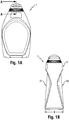
- the invention is directed to an apparatus (1) for repeatedly dosing a quantity of liquid, in which the quantity of liquid dosed can be readily adjusted to suit the user's requirement.
- the apparatus (1) comprises a resiliently squeezable container (2), a cap (3) operably connected to said container (2), and a dosing chamber (4) operably connected to said cap (3).
- the dosing chamber (4) comprises a dosing chamber base (12) having a discharge opening (13) therein, dosing chamber sidewalls (14) extending upwardly along the perimeter of said dosing chamber base (12) and at least one dosing chamber one inlet opening (15) located proximal said dosing chamber sidewalls (14); There is at least one timer aperture (16) located proximal to said discharge opening (13).
- a plunger is provided in said dosing chamber (4) and is moveable relative to said chamber so as to advance upon squeezing of said container (2), up to a blocking position.
- a valve retaining means (6) is located below said dosing chamber base (12).
- a valve (7, 29, 33) provided in said valve retaining means (6) is movable from an open position, allowing liquid flow through said discharge opening (13), and a closed position, where the valve blocks said discharge opening.
- the dosing apparatus also comprises a nozzle.
- the apparatus (1) may have a longitudinal axis (YY) extending along/or substantially parallel to, the centerline of the apparatus (1). Said longitudinal axis (YY) may also be parallel to the direction of a portion of the fluid flow during dispensing.
- the distance the plunger can move from the dosing chamber base (12) to the blocking position defines a travel distance and the blocking position can be altered to provide a minimum travel distance and a maximum travel distance, such that the minimum travel distance, for delivering the minimum dose, is from 5% to 66%, preferably from 10% to 50%, more preferably from 15% to 30% of the maximum travel distance, for delivering the maximum dose.
- the dosing apparatus (1) can dispense a volume from the minimum dose setting which is from 5% to 66%, preferably from 10% to 50%, more preferably from 15% to 30% of the volume dispensed from the maximum dose setting.
- the "high" dose can be from 10 ml to 100 ml, preferably from 15 ml to 50 ml, more preferably from 20 ml to 30 ml.
- the "low” dose can be from 0.1 ml to 5.0 ml, preferably from 0.2 ml to 2.5 ml, more preferably from 0.3 ml to 1.0 ml.
- a smaller dose is desired for direct application on to a stain on a hard surface, before scrubbing.
- the "high" dose can be from 20 ml to 150 ml, preferably from 25 ml to 120 ml, more preferably from 30 ml to 90 ml.
- the "low” dose can be from 1 ml to 17.5 ml, preferably from 2.5 ml to 15 ml, more preferably from 5.0 ml to 10 ml.
- the blocking position can be altered by any suitable means.
- the dosing apparatus (1) can comprise a dosing element (34), wherein the dosing element comprises a dosing element top (35) which is positioned above the dosing chamber (4) and is moveable such that the blocking position can be altered.
- dosing elements (34) comprise the nozzle (8).
- the nozzle (8) comprises and/or defines an orifice (9) at its apex, and an entry tube (10) which extends downwardly and opposite said orifice (9).
- the dosing element top (35) comprises the nozzle (8) extending substantially parallel to the longitudinal axis (YY) preferably comprising and/or defining an orifice (9) at its apex, and an entry tube (10) which extends downwardly and opposite said orifice (9).
- Said orifice (9) can comprise a slit valve to reduce and even eliminate dripping.
- the entry tube (10) may extend vertically downwardly substantially parallel to the longitudinal axis (YY) so as to at least partly enter a volume formed by the dosing chamber (4).
- the cap (3) or dosing element top (35) may further comprise a top lid (17) capable of engaging with the nozzle (8) to provide a closing and sealing means.
- the cap (3) comprises the top lid (17).
- the top lid (17) may be pivotable upon a pivot point located on a surface of the cap (3).
- other closing features or cap constructions could also be used, such as a push-pull closure as exemplified in Fig. 5 , or twist, screw or other caps know in the art.
- the dosing chamber (4) comprises a dosing chamber base (12) having a discharge opening (13) located therein.
- the discharge opening (13) is located at the centre of the dosing chamber base (12) to allow the liquid accumulated in the volume (11) of the dosing chamber (4) below the plunger to be quickly flushed back into the container (2) after squeezing.
- At least one timer aperture (16) is located proximal to the discharge opening (13).
- the dosing chamber (4) also has dosing chamber sidewalls (14) extending upwardly along the perimeter of the dosing chamber base (12) and have at least one dosing chamber one inlet opening (15) located proximal to said dosing chamber sidewalls (14).
- the dosing chamber inlet openings (15) are located proximal to the apex of the dosing chamber sidewalls (14) opposite the dosing chamber base (12) of the dosing chamber (4).
- the dosing chamber base (12) of the dosing chamber (4) may be chamfered to form an inclined surface extending from the dosing chamber sidewalls (14) to the discharge opening (13).
- said inclined surface extends substantially linearly from said dosing chamber sidewalls (14) to said discharge opening (13).
- Such configuration allows the liquid to drain from the dosing chamber (4) in an effective manner without leaving any left-behind residue, particularly in locations proximal to the dosing chamber sidewalls (14), which would otherwise cause jamming of the plunger upon drying.
- the dosing element (34) can further comprise dosing element sidewalls (36) extending downwardly along the perimeter of the dosing element top (35), with the entry tube (10) extending downwardly and opposite the orifice (9), and the dosing element sidewalls (36) contact the dosing chamber sidewalls (14).
- the dosing element (34) is able to move within the dosing chamber (4), in order to vary the distance between the lowest point of the entry tube (10) and the dosing chamber base (12), as exemplified in Fig. 3A to 3C .
- the dose of liquid can be adjusted by altering the position of the dosing element (34), and hence the entry tube (10), relative to the dosing chamber base (12).
- the dosing element (34) can be moved relative to the dosing chamber base (12) by a sliding motion or rotational motion.
- the outer surface of the dosing element sidewalls (36) can comprise a ridge in the form of a screw-thread, whilst the inner surface of the dosing chamber sidewalls (14) can comprise the corresponding grooves for the screw thread, or vice-versa (see Fig. 7A and 7B ).
- the dosing element sidewalls (36) can contact the dosing chamber sidewalls (14) over the circumference of the dosing element sidewalls (36), preferably such that liquid is not able to leak between the dosing element sidewalls (36) and dosing chamber sidewalls (14).
- the dosing element sidewalls (36) can be irremovable from the dosing chamber sidewalls (14). This can be achieved using any suitable means, for instance, having a bead on the exterior face of the dosing element sidewalls (36), distal from the dosing element top (35), and the dosing chamber sidewalls (14) comprising a step or lip which abuts the bead when the dosing element (34) is at its furthest position from the dosing chamber base (12).
- the nozzle (8) can comprise an entry tube (10), wherein the entry tube (10) is moveable relative to the nozzle (8) such that the blocking position can be altered (see Fig. 6A and 6B ).
- the entry tube (10) preferably contacts the nozzle (8) over the circumference of the entry tube (10), such that liquid is not able to leak between the entry tube (10) and the nozzle (8).
- the entry tube (10) is capable of displacing both upwardly and downwardly in a direction parallel to the longitudinal axis (YY) upon rotation of the cap (3). Changing the height of the entry tube (10) reduces the travel distance of the piston thus allowing the user to dose different quantities of liquid by simply rotating cap (3).
- the entry tube (10) of the dosing element (34) is able to move within nozzle (8), in order to vary the travel distance between the lowest point of the entry tube (10) and the dosing chamber base (12). Since the dose provided by the apparatus (1) varies with the distance that the plunger can move between the lowest point of the entry tube (10) and the dosing chamber base (12), the dose of liquid can be adjusted by altering the position of the dosing element (34), relative to the dosing chamber base (12).
- the entry tube (10) can be moved relative to the dosing chamber base (12) by a sliding motion or rotational motion.
- the outer surface of the entry tube (10) can comprise a ridge in the form of a screw-thread, whilst the inner surface of the nozzle (8) can comprise the corresponding grooves for the screw thread.
- the entry tube (10) can be irremovable from the nozzle (10). This can be achieved using any suitable means.
- the entry tube (10) can comprise a bead (38) either at its extremity distal from the orifice (9) or positioned on the sidewall of the entry tube (10) (see Fig. 6A and 6B ). Hence, when the dosing element (34) is at its furthest position from the dosing chamber base (12), the bead (38) abuts the nozzle (10).
- the nozzle (8) can be comprised on the cap (3).
- the nozzle (8) can be comprised on the dosing element ((34), particularly the dosing element top (35) as shown in Fig. 3A to 3C and Fig. 6A and 6B .
- the dosing element sidewalls (36) can comprise at least one dosing element inlet opening (37) located proximal said dosing chamber sidewalls (14).
- the at least one dosing element inlet opening (37) can at least partially overlap with the at least one dosing chamber inlet opening (15).
- the dosing element (34) is rotatable, the dosing element (34), and hence the dosing element side walls (36) can be rotated such that the overlap between the at least one dosing element inlet opening (37) and the at least one dosing chamber inlet opening (15) can be altered.
- the dosage provided by the dosing apparatus (1) can be further altered.
- the dosing apparatus (1) When the dosing element (34) can be rotated such that there is no overlap between the at least one dosing element inlet opening (37) and the at least one dosing chamber inlet opening (15), the dosing apparatus (1) is closed. In addition, by rotating the rotatable element (34), the relative distance between at least one dosing element inlet opening (37) and the dosing chamber base (12) is also altered.
- the ratio of the total cross-sectional open area of dosing chamber inlet openings (15) and the timer apertures (16) can be between 2 to 25, preferably from 2 to 24, preferably from 2 to 23, preferably from 4 to 22, preferably from 6 to 22, more preferably from 8 to 20, most preferably 10 to 18
- the plunger is preferably in the form of a piston (5) and is moveable relative to the dosing chamber base (12) so as to advance upon squeezing of the inverted container (2).
- the piston (5) moves from a starting position - wherein the piston (5) is at its furthest position from the entry tube (10), up to a blocking position - wherein at least part of the piston (5) contacts the entry tube (10) so as to close it and terminating the dose.
- the motion of the piston (5) is linear and parallel to the longitudinal axis (YY), however, it is understood that any other kind of motion such as rotation and combination of rotation and translation may be equally suitable for generating a dose. Since the blocking position, typically the lowest point of the entry tube (10), can be altered, the distance that the plunger, preferably the piston (5), can traverse can be changed. Hence, the dose delivered by the apparatus can be altered.
- the valve retaining means (6) is located below the dosing chamber base (12) of the dosing chamber (4) and may extend vertically downward from said dosing chamber base (12) in a direction substantially parallel to the longitudinal axis (YY).
- the valve retaining means (6) is one part with the dosing chamber (4). This allows to reduce the number of parts required and contributes towards introducing benefits such as reduced manufacturing complexity and cost, and ease of assembly.
- the valve (7) is preferably uni-directional (i.e. it opens and closes in one direction only) and is provided in the retaining means (6).
- the valve (7) is moveable from an open position - allowing liquid to flow through the discharge opening (13), and a closed position - wherein the valve blocks said discharge opening (13).
- said valve (7) may be spherical in shape and may be capable of blocking the discharge opening (13) by at least partly entering the dosing chamber (4).
- said valve maybe capable of contacting and/or impacting and/or abutting at least part of the piston (5) when said piston (5) is in its starting position and said valve (7) is in its closed position upon squeezing of the resilient container (2).
- Such configuration allows easy and accurate location of the valve into the discharge opening upon squeezing of the container (2) with no need for a specific orientation to be maintained.
- valve (7) acts as a precursor and pushes up the piston so as to overcome any initial jamming of said piston (5).
- the piston (5) may have a substantially flat surface, preferably a flat surface, and may comprise stabilizing wings (24) extending upwardly and substantially parallel to the longitudinal axis (YY).
- the root of said stabilizing wings (24) may be located along the circumference of said piston (5).
- Said stabilizing wings may be spaced apart so as to minimize material used and any friction with the dosing chamber sidewalls (14) and the dosing element side walls (36).
- the diameter of said piston (5) may be smaller than the diameter of said dosing chamber (4) to further reduce any friction effects between the surfaces thereof.
- said piston (5) may further comprise protrusions (25) extending opposite and mirrored to said stabilizing wings (24) wherein said protrusions (25) are of smaller length than said stabilizing wings (24).
- protrusions (25) are of smaller length than said stabilizing wings (24).
- the dosing chamber (4) may comprise dosing chamber sidewalls (14) extending vertically upwardly along the perimeter of dosing chamber base (12) and parallel to the longitudinal axis (YY).
- the dosing chamber (4) maybe integrally molded to the cap (3).
- the dosing chamber (4) can be separately formed, for instance by injection molding, before being attached to the cap (3).
- the dosing chamber sidewalls (14) and cap (3) can comprise corresponding protrusions and grooves, in order to "snap-fit" the dosing chamber (4) to the cap.
- the dosing chamber sidewalls (14) can comprise at least two tabs (18) extending vertically upwardly from the apex of said dosing chamber sidewalls (14) in a direction opposite to said dosing chamber base (12).
- the tabs (18) may be spaced apart so as to form a castellation on the upper portion of the dosing chamber (4).
- Such tabs (18) may define dosing chamber inlet openings (15) formed by the open space between said tabs (18).
- the perimeter of said dosing chamber base (12) may be substantially circular, however it is understood by the person skilled in the art that other shapes may also be suitable such as oval, squared, triangular and so on. This configuration allows for ease of manufacture of the dosing chamber inlet openings (15).
- the dosing chamber comprises multiple tabs (18) forming multiple dosing chamber inlet openings (15).
- the tabs (18) may further comprise a notch which may follow the contour of the inside face of said tabs (18) and extend a predetermined length towards the longitudinal axis (YY), for compliance with a groove located on a surface of the cap (3).
- said surface of cap (3) faces opposite to said longitudinal axis (YY) and is located on a first skirt (21).
- Said first skirt (21) may extend downwardly and substantially parallel to said longitudinal axis (YY) from a first surface of the cap (3) (see Fig. 8 ).
- the dosing chamber (4) maybe connected to the cap (3) by snap fitting said tabs (18) to said first skirt. Such a construction allows for ease of assembly.
- timer apertures (16) may be located in the dosing chamber base (12) of the dosing chamber (4).
- said timer apertures (16) may be proximal to the discharge opening (13) and the centre line of said timer apertures (16) maybe parallel to the centre line of said discharge opening (13).
- the timer apertures (16) may be in the form of multiple slots extending for a predetermined length from the discharge opening (13) towards the dosing chamber sidewalls (14) through the dosing chamber base (12) of the dosing chamber (4).
- the piston (5) comprises a ring-like protrusion extending from the base thereof in a direction substantially parallel to the longitudinal axis (YY) towards said dosing chamber base (12). The said ring-like protrusion may be capable of closing the multiple slots and the discharge opening (13) when in its starting position by being in relative contact with the corresponding surface of said dosing chamber base (12) of said dosing chamber (4).
- An advantage of this configuration is that bubbling through the timer apertures is significantly reduced and even prevented when the filled container is inverted without squeezing it.
- air may flow through the timer holes causing a back pressure differential that results in some of the liquid to flow in the dosing chamber (4) through the dosing chamber inlet openings (15) and leak. Consistent dosing is therefore improved over different tilt angles and also at different container fill levels.
- timer apertures (16) may be located in and/or through the valve (29, 33), as illustrated in Fig. 10A to 10B and Fig. 11 .
- the dosing chamber base (12) of the dosing chamber (4) may be chamfered in such a way to define a first area and a second area.
- said first area may be demarcated by the dosing chamber sidewalls (14) of the dosing chamber (4), and said second area may define the circumference of the discharge opening (13). More preferably, the said second area is located below said first area and the centerline of said first area coincides with the centerline of said second area.
- the cap (3) may comprise a second skirt forming aplug seal (22) extending downwardly proximal to the first skirt (21), and a v-shaped notch (23) proximal to said second skirt (22).
- the plug-seal (22) and the V-shaped notch (23) may be capable of at least partly engaging with the uppermost surface of the container (2) so as to provide a secure sealing means and prevent leakage during dosage.
- the first skirt (21) may comprise shutter tabs in the form of spaced flanges or the like to at least partly cover at least one of the dosing chamber inlet openings (15).
- the first skirt (21) may have shutter tabs formed by portions of the first skirt (21) subtending at a variable vertical distance taken from a plane substantially parallel to the longitudinal axis (YY) to form a series of preferably linear gradients along the entire circumference of said first skirt (21).
- the first skirt (21) may be rotatable with respect to the dosage chamber (4) so as to allow more variation in the size of the dosing chamber inlet openings (15). This allows greater flexibility in dosage whereby the user can dispense different amounts of liquid by rotating the cap (3) which in turn changes the size of said inlet openings and thus the ratio of the surface of said dosing chamber inlet openings (15) and the timer apertures (16).
- the valve retaining means (6) may be formed by at least three flexible hook-shaped protrusions (26) extending downwardly from said dosing chamber base (12) in a direction opposite to the dosing chamber sidewalls (14) of the dosing chamber (4) and substantially parallel to the longitudinal axis (YY).
- An advantage of such hook shaped protrusions (26) is the simplification of the de-molding operation during manufacturing by allowing pull-off from the injection mold without complex slides in the mold.
- a further advantage is that said hook shaped protrusions (26) allow to assemble the valve (7) easily via push-fit, while minimizing contact between said valve (7) and said hook shaped protrusions (26) which aids in preventing blockage.
- the retaining means (6) may further comprise at least one flat panel extending downwardly from said dosing chamber base (12) and substantially parallel to the longitudinal axis (YY). Said panels are preferably located in the gaps formed between the hook-shaped protrusions (26). This configuration allows to securely locate the valve (7) inside the retaining means (6) in a child-proof manner by preventing the removal of the valve (7) once inserted.
- the valve retaining means (6) may be formed by at least two overhangs, preferably at least three overhangs, extending downwardly from said dosing chamber base (12) in a direction opposite to the dosing chamber sidewalls (14) of the dosing chamber (4) and substantially parallel to the longitudinal axis (YY).
- a snap ring may join to the apex of said overhangs so as to define a valve insertion opening at the centre thereof.
- the snap ring may extend towards the centre of the valve insertion opening, and may be inclined at an angle from a plane perpendicular to said longitudinal axis (YY).
- said angle is about 35° prior to the insertion of the valve through the valve insertion opening and deforms in a direction towards said dosing chamber base (12) when the valve is pushed through the valve insertion opening.
- the resulting angle of said snap ring after valve insertion is preferably -45° taken along said plane perpendicular to said longitudinal axis (YY).
- said overhangs and said snap ring are one part with said dosing chamber (4).
- the valve retaining means (6) maybe formed by a projection (32) extending from said dosing chamber base (12) in a direction opposite to said dosing chamber sidewalls (14) and may engage with a flexible one-way disc valve (33) with a very low cracking pressure (i.e. low minimum upstream pressure at which the valve will operate).
- the valve (33) may be engaged to said valve retaining means (6) via a central snap fit or other means which allows movement of said valve (33) relative to said projection (32).
- the valve (33) may be substantially flat and circular in shape, although it is understood that other shapes may also be suitable such as dome shaped and/or umbrella shaped.
- the valve (33) may have timer apertures (16) extending therein.
- the valve (29) may be bullet shaped. Said bullet shape is defined by a substantially flat surface (30) on one end and a substantially convex surface (31) on the opposite end.
- the valve (29) may be inserted into the valve retaining means (6) via a snap fit or other means which allows movement of said valve (29) relative to said valve retaining means, the valve retaining means (6) guiding the valve (29) and preventing it from changing orientation.
- the flat surface of said valve may have an opening subtending more than 50% of the diameter of said valve (29) and the convex surface (31) may have one or more timer apertures (16) located proximal to the apex of said convex surface.
- the valve (29) maybe oriented so that the convex surface (31) faces the discharge opening (13) and the flat surface (30) faces the inside of the container (2).
- the container (2) may comprise a front (27) and a back (28) surface in a facing relationship.
- said front (27) and back (28) surfaces have a larger surface area compared to the other surfaces of the container (2) and are spaced apart so that the distance (d) between said front (27) and back (28) surfaces is between 30mm to 100mm. This specific range has been found to be optimal for allowing the user to correctly and comfortably grip the container and squeeze effectively.
- the container (2) may be made of any flexible material, however, preferably said material is selected from the group consisting of PP, PET, PE or blends thereof. Said container (2) may be capable of displacing from 5ml to 150ml, preferably from 10ml to 80ml, of liquid without experiencing permanent deformation. Without being bound by theory it is believed that permanent deformation will create cracks in the container or cause paneling (i.e. the panels do not return to the starting position) which in turn reduce the displacement volume with each use, affecting the consistency of the dosage.
- the container (2) may comprise an indicating means to indicate to the user the acceptable inclination angle of the apparatus (1) for effective dosage. Indeed, in some operations the user may need to angle the apparatus (1) due to space restrictions or simply comfort. However, tilting the apparatus (1) at too shallow angles may result in loss of accuracy of the dosage, particularly if air starts flowing through the dosing chamber inlet openings (15). This may be particularly true when the liquid is close to depletion. It may therefore be necessary to incline the apparatus (1) as much as possible but in such a way that the liquid still covers said dosing chamber inlet openings (15). An indicating means allowing the user to see when said liquid covers said dosing chamber inlet openings (15) may be desirable.
- said indicating means is a transparent window located on said container (2) proximal to the connecting portion of the cap (3) with said container (2).
- said indicating means may be an entirely transparent container.
- the container (2) can comprise a front surface (27) and a back surface (28), wherein the distance between said front to said back surfaces is between 30mm to 120mm.
- An advantage of the present invention is that constant dosage during use (i.e. as the liquid being dispensed is depleted from the container) is achieved whilst providing optimal ergonomics for the end user who can dispense a dose of liquid without experiencing strain during the squeeze operation, and allowing the dose size to be readily altered according to need.
- the dosing apparatus of the present invention consists of an ergonomic dosing apparatus.
- the dosing apparatus delivers a dose of liquid at a pressure of less than 150kPa, preferably less than 120 kPa, preferably less than or equal to 110 kPa, more preferably from 80 kPa to 110kPa, even more preferably from 90 kPa to 100kPa, measured according to the test method described herein.
- a pressure of less than 150kPa preferably less than 120 kPa, preferably less than or equal to 110 kPa, more preferably from 80 kPa to 110kPa, even more preferably from 90 kPa to 100kPa, measured according to the test method described herein.
- the dosage time is typically less than or equal to 3s, preferably less than or equal to 2s, preferably less than or equal to 1.5s, preferably less than or equal to 1s and more preferably less than or equal to 0.75s but greater than 0s, most preferably from 0.4s to 0.75s.
- the time of squeeze is too high, the user will apply a more variable squeezing force with the greatest force being applied towards the end of the squeeze resulting in the user experiencing an undesired fatigue especially in circumstances where multiple doses are required.
- the ratio of the total cross-sectional open area of the dosing chamber inlet openings (15) and the orifice (9) may also affect the dose, in particular if the total cross-sectional open area of the orifice is smaller than the total cross-sectional open area of the inlet openings.
- the orifice (9) is too large, dripping may occur which would require the introduction of additional features to minimize said dripping such as silicone or thermoplastic elastomers (TPE) slit-seal valves and/or cross-shaped cuts in the orifice.
- the ratio of the total cross-sectional open area of said dosing chamber inlet openings (15) and said orifice (9) may be from 4 to 0.25, preferably 1.
- the ratio of the exposed cross-sectional area of the dosing chamber inlet openings (15) and the orifice (9) may be selected such that the speed of dosage is less than or equal to 1.5s, preferably less than or equal to 1s and more preferably less than or equal to 0.75s, at ratios of total surface of the exposed cross-sectional area of the inlet openings (15) : timer apertures (16) of from 15 to 25, preferably 18 to 25, more preferably 22 to 25.
- the dose of liquid being expelled through the nozzle has a flow rate of greater than 20g/s, preferably greater than 25g/s, preferably greater or equal to 30g/s, more preferably greater or equal to 35g/s, more preferably greater or equal to 38g/s, more preferably greater or equal to 40g/s, even more preferably from 42g/s to 70g/s, even more preferably from 45g/s to 65g/s, most preferably from 50g/s to 60g/s, typically measured for the first 10 squeezes starting from a full container.
- full container it is herein intended that the resilient container of the apparatus is filled with liquid as much as is normal in the field of detergent bottles, this is typically about 90% of the total inner volume of the container. Without wishing to be bound by theory it is believed that lower flow rates provide detriment to the ergonomic squeeze.
- the viscosity and rheology profile of the liquid may impact the accuracy, speed of dosage, and comfort in the squeeze operation. It has been found that liquids having a shear thinning-type rheology profile and viscosity within the below-mentioned ranges ensure an acceptable force to be applied to the resilient container and thus permit an ergonomic squeeze of the container to provide a drip-free dose.
- the liquids herein have a viscosity of from 1 to 350 mPa•s, preferably 1 to 300 mPa•s, more preferably from 1 to 250 mPa•s, even more preferably 1 to 220 mPa•s, measured at 1000s -1 at 20°C.
- the above viscosities will deliver a constant dose of liquid whilst permitting such ergonomic squeeze. If the viscosity of the liquid is above the mentioned ranges, an unacceptable amount of force is required to be applied by the user to complete a dose.
- the viscosity measurements referred to herein are taken with an AR 1000 from TA instruments with a 2° 1' 5" cone angle spindle of 40mm diameter with truncation of 57 micrometer.
- Constant dose it is herein meant that the variation in dose over multiple squeezes, typically 10 consecutive squeezes starting from a full container, does not exceed ⁇ 3ml, preferably ⁇ 1ml.
- liquids having a viscosity of greater than 150 (and the below mentioned preferred ranges) at low shear (i.e. 10s -1 at 20°C) in combination with the apparatus according to the present invention, provides a dose of liquid substantially drip-free but also provide the necessary feel and control to the user in the squeeze operation. At the same time, ensuring that the same liquid has a high shear viscosity (i.e.
- the apparatus according to the present invention comprises a resilient container comprising a shear thinning liquid therein typically having a viscosity, at a shear rate of 10s -1 at 20°C, of more than 1 time, preferably at least 1.5 times, preferably 2 times, preferably from 2 to 100 times, more preferably from 3 to 50 times, even more preferably from 4 to 20 times, even more preferably from 5 to 15 times, most preferably from 6 to 10 times, greater than the viscosity at a shear rate of 1000s -1 at 20°C.
- the low shear viscosity (i.e. at 10s -1 at 20°C) is greater than 150mPa•s, preferably greater than 200 mPa•s, more preferably greater than 250mPa•s, even more preferably greater than 300 mPa•s. Viscosities below the above ranges result in undesirable dripping which not only provides unsightly residues being formed on the cap proximal to the orifice and messiness but also considerably affects consistency of the dosage.
- compositions suitable for use in the apparatus of the present invention are formulated as liquid compositions, preferably liquid detergent compositions, typically comprising water, preferably in an amount from 10% to 85% by weight of the total composition.
- suitable compositions maybe acidic or alkaline or both, and may further comprise abrasive cleaning particles, suspending aids, chelating agents, surfactants, radical scavengers, perfumes, surface modifying polymers, solvents, builders, buffers, bactericides, hydrotropes, colorants, stabilizers, bleaches, bleach activators, suds controlling agents like fatty acids, enzymes, soil suspenders, anti dusting agents, dispersants, pigments, thickeners, and/or dyes.
- the liquid compositions herein consist of a compact liquid.
- compact means a composition having densities in the range of from 0.5 to 1.5 grams, preferably from 0.8 to 1.3 grams, more preferably from 1 to 1.1 grams, per cubic centimeter, excluding any solid additives but including any bubbles, if present.
- the compact liquid typically has an undiluted viscosity "Vu" of from 1 to 350 mPa•s, preferably 1 to 300 mPa•s, more preferably from 1 to 250 mPa•s, even more preferably 1 to 220 mPa•s, at high shear (measured at 1000s -1 at 20°C) and of greater than 150mPa•s, preferably greater than 200 mPa•s, more preferably greater than 250mPa•s, even more preferably greater than 300 mPa•s, even more preferably from 300 mPa•s to 15000 mPa•s, even more preferably from 300 mPa•s to 10000 mPa•s, most preferably from 300 mPa•s to 5000 mPa•s at low shear (measured at 10s -1 at 20°C), and a diluted viscosity "Vu" of from 1 to 350 mPa•s, preferably 1 to 300 mPa•s, more
- the water that is used to prepare the aqueous solution for determining the diluted viscosity Vd of a composition is deionized water.
- the dilution procedure is described below.
- the advantage of such embodiment is that highly concentrated compositions may be formulated in the apparatus of the present invention whilst still achieving the desired consistency in drip-free dosage.
- a compact liquid composition having the above diluted viscosity "Vd” is important to ensure high dissolution.
- a compact liquid composition with high undiluted viscosity "Vu” important to ensure drip-free and constant dosing, will generally dissolve poorly, unless it is so formulated as to have a lower viscosity on dilution, as in the present highly preferred embodiment of the invention.
- the liquid contained in the container consists of a liquid detergent composition
- a rheology modifier comprising, preferably consisting of, polyacrylate based polymers, preferably hydrophobically modified polyacrylate polymers; hydroxyl ethyl cellulose, preferably hydrophobically modified hydroxyl ethyl cellulose, xanthan gum, hydrogenated castor oil (HCO) and mixtures thereof.
- Preferred rheology modifiers are polyacrylate based polymers, preferably hydrophobically modified polyacrylate polymers.
- a water soluble copolymer based on main monomers acrylic acid, acrylic acid esters, vinyl acetate, methacrylic acid, acrylonitrile and mixtures thereof, more preferably copolymer is based on methacrylic acid and acrylic acid esters having appearance of milky, low viscous dispersion.
- Most preferred hydrologically modified polyacrylate polymer is Rheovis® AT 120, which is commercially available from BASF.
- Suitable rheology modifiers are hydroxethylcelluloses (HM-HEC) preferably hydrophobically modified hydroxyethylcellulose.
- HM-HEC Suitable hydroxethylcelluloses
- Xanthan gum is one suitable rheology modifier for liquids used herein.
- Xanthan gum is produced by fermentation of glucose or sucroce by the xanthomonas campestris bacterium.
- Suitable Xanthan gum is commercially available under trade anem Kelzan T® from CP Kelco.
- Hydrogenated castor oil is one suitable rheology modifier used herein. Suitable hydrogenated castor oil is available under trade name TIXCIN R from Elementis.
- the most preferred rheology modifier used herein is hydrologically modified polyacrylate polymer Rheovis® AT 120, which is commercially available from BASF.
- the thickened liquid hard surface cleaning composition herein comprises from 0.1% to 10.0% by weight of the total composition of said thickener, preferably from 0.2% to 5.0%, more preferably from 0.2% to 2.5% and most preferably from 0.2% to 2.0%.
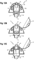
- Fig. 12A to 12C illustrate an example of the operation of apparatus (1).
- Fig. 10A illustrates the resting position of apparatus (1), prior to use.
- the user disengages the top lid (17) or opens the orifice (9) and inclines the apparatus (1) top down, in a substantially inverted position.
- the user squeezes the container (2) preferably with one hand to begin the dosage.
- the liquid flow causes the valve (7) to close the discharge opening (13) and the liquid to flow through the timer apertures (16) causes the piston (5) to move towards the entry tube (10).
- Concurrently the liquid forced through the dosing chamber inlet openings (15) is discharged through the entry tube (10) and out of the nozzle (8).
- Fig. 10A illustrates the resting position of apparatus (1), prior to use.
- the user disengages the top lid (17) or opens the orifice (9) and inclines the apparatus (1) top down, in a substantially inverted position.
- the user squeezes the container (2) preferably with one hand to begin the dosage
- FIG. 12B shows the apparatus (1) in its dosing arrangement with the piston (5) at its mid position.
- the user may squeeze said container for no more than 1.5 seconds, preferably no more than one second, to complete the dose.
- the volume of liquid dosed for each squeeze of the container (2) may be from 1ml to 80ml, preferably from 3ml to 40ml, more preferably 10ml to 30ml, and even more preferably 10ml to 25ml.
- Fig. 12C illustrates the arrangement of apparatus (1) at the end of the dosage.
- the dose is complete and the user may release the force from said container (2).
- the valve is then opened by the pressure differential generated as the resilient container (2) deforms back to its original shape, and the liquid is discharged into the container (2) through the discharge opening (13) allowing the piston (5) to return to its starting position.
- the user may now re-squeeze said container (2) to dispense a new dose, without the need of re-inverting the apparatus (1). This process maybe repeated for all subsequent dosages as necessary.
- Viscosity measurements The viscosity of liquid compositions herein, including Vu and Vd, is measured using an AR 1000 from TA Instruments with a 2° 1' 5" cone angle spindle of 40mm diameter with truncation of 57 micrometer, shear rate factor of 28.6, and shear stress factor of 0.0597.
- the software used is the TA Instruments software, version 3.03 or higher. The following settings are used: a pre-shear with a shear rate of 10s -1 for 10 seconds with 1 minute equilibration and a shear rate continuous ramp of from 0.1s -1 till 1200s -1 , during 3 minutes with 32 points per decade. All measurements are carried out at room temperature at 20°C.
- the compact liquid composition is diluted with deionized water according to the following protocol. 100g of composition are weighed in a plastic beaker. The beaker is stirred with a mechanical stirrer rotating at low speed 200rpm to avoid entrapment of air into the product. While stirring, 50ml of deionized water are added to the composition. The composition is stirred for 4 minutes, until the composition is fully homogeneous. The composition is allowed to rest for 15 minutes before starting the viscosity measurement. The entire procedure is carried out at room temperature at 20°C.
- Pressure measurements - A pressure sensor of the type MSR145 IP67 waterproof mini data logger from MSR Electronics GmbH (frequency of 1/10s, pressure range 0-2000mBar ⁇ 2.5mBar) is inserted into a container according to the present invention filled with a liquid according to the present invention. The cap and the remaining components of the apparatus according to the present invention are then fitted to close the container. Repeated doses of liquid are prepared by repeated squeezes of the apparatus in top down vertical orientation, typically 10 consecutive squeezes starting from a full container.
- the squeezing is carried out by a robot with a two point squeeze and having a Festo sfc-dc-vc-3-e-h2-co control box and Festo hgple-25-40-2.8-dc-vcsc-g85 motor, that is set to compress the container at a speed "v" of 20mm/s and acceleration "a" of 100mm/s 2 , and using the below protocol (typically the relative distance "xt" is 32mm for containers holding 400ml, 33mm for 520ml containers, 27.5mm for 600ml containers and 21mm for 946ml containers). Pressure readings are recorded by the sensor. Such measurements are repeated for apparatuses having a wide range of inlet and timer aperture ratios and for a range of viscosities.
- Determining acceptable squeeze ergonomics - Acceptable squeeze ergonomics is determined via testing a number of apparatuses according to the present invention with an expert panel. Panelists are asked to rate a number of different apparatuses in terms of comfort and easiness of squeeze to generate a complete dose of liquid. Panelists are asked to squeeze apparatuses having different inlet and timer aperture ratios and different viscosity profiles. The results are recorded.
- Flow rate measurements - A pressure sensor of the type MSR145 IP67 waterproof mini data logger from MSR Electronics GmbH (frequency of 1/10s, pressure range 0-2000mBar ⁇ 2.5mBar) is inserted into a container according to the present invention filled with a liquid according to the present invention. The cap and the remaining components of the apparatus according to the present invention are then fitted to close the container. Repeated doses of liquid are prepared by repeated squeezes of the apparatus in top down vertical orientation, typically 10 consecutive squeezes starting from a full container.
- the squeezing is carried out by a robot with a two point squeeze and having a Festo sfc-dc-vc-3-e-h2-co control box and Festo hgple-25-40-2.8-dc-vcsc-g85 motor, that is set to compress the container at a speed "v" of 20mm/s and acceleration "a" of 100mm/s 2 and using the below protocol (typically the relative distance "xt" is 32mm for containers holding 400ml, 33mm for 520ml containers, 27.5mm for 600ml containers and 21mm for 946ml containers). Pressure readings are recorded by the sensor. Such measurements are repeated for apparatuses having a wide range of inlet and timer aperture ratios and for a range of viscosities.
- the weight of each dose and the time to deliver the dose is recorded. The time is recorded with a high speed camera at 300 frames/second.
- the flow rate for each dose is calculated by dividing the mass of the dose delivered by the time taken to complete the dose.
- Protocol for robot squeeze The apparatus to be tested is mounted upright in the robot arm. The settings for speed and acceleration are adjusted to the above mentioned parameters. The apparatus is turned top down and then squeezed until the dose is complete. The apparatus is turned upright and then the squeeze is released. Pressure, mass and time parameters are recorded as explained above. The process is repeated, typically 10 times for each condition and readings recorded each time.
Priority Applications (3)
| Application Number | Priority Date | Filing Date | Title |
|---|---|---|---|
| EP16195522.4A EP3315922B1 (fr) | 2016-10-25 | 2016-10-25 | Appareil de dosage de liquides |
| PCT/US2017/057810 WO2018080964A1 (fr) | 2016-10-25 | 2017-10-23 | Appareil de dosage de liquide |
| US15/791,450 US10488240B2 (en) | 2016-10-25 | 2017-10-24 | Liquid dosing apparatus |
Applications Claiming Priority (1)
| Application Number | Priority Date | Filing Date | Title |
|---|---|---|---|
| EP16195522.4A EP3315922B1 (fr) | 2016-10-25 | 2016-10-25 | Appareil de dosage de liquides |
Publications (2)
| Publication Number | Publication Date |
|---|---|
| EP3315922A1 true EP3315922A1 (fr) | 2018-05-02 |
| EP3315922B1 EP3315922B1 (fr) | 2020-01-08 |
Family
ID=57208143
Family Applications (1)
| Application Number | Title | Priority Date | Filing Date |
|---|---|---|---|
| EP16195522.4A Active EP3315922B1 (fr) | 2016-10-25 | 2016-10-25 | Appareil de dosage de liquides |
Country Status (3)
| Country | Link |
|---|---|
| US (1) | US10488240B2 (fr) |
| EP (1) | EP3315922B1 (fr) |
| WO (1) | WO2018080964A1 (fr) |
Cited By (1)
| Publication number | Priority date | Publication date | Assignee | Title |
|---|---|---|---|---|
| WO2023111462A1 (fr) | 2021-12-17 | 2023-06-22 | Aptar France Sas | Distributeur de produit fluide |
Families Citing this family (4)
| Publication number | Priority date | Publication date | Assignee | Title |
|---|---|---|---|---|
| PL3384249T3 (pl) * | 2015-12-02 | 2019-12-31 | Raepak Limited | Urządzenie dozujące oraz pojemnik |
| CN109625583B (zh) * | 2018-12-29 | 2023-09-15 | 珠海经济特区美司达实业有限公司 | 一种倾倒式定量可调的液体分配器 |
| WO2022236219A1 (fr) * | 2021-04-20 | 2022-11-10 | Flexpenser Ab | Applicateur de dosage pour récipients médicaux et non médicaux |
| US11860017B2 (en) * | 2022-02-28 | 2024-01-02 | L'oreal | Cosmetic dispenser with bladder valve system |
Citations (6)
| Publication number | Priority date | Publication date | Assignee | Title |
|---|---|---|---|---|
| GB975288A (en) * | 1961-06-08 | 1964-11-11 | Seary Ltd | Improvements in metering button cap |
| WO2000008425A1 (fr) * | 1998-08-03 | 2000-02-17 | Createchnic Ag | Dispositif de dosage et de mesure pour fluides coulants |
| DE202004014129U1 (de) * | 2004-09-11 | 2004-12-30 | Kaspers, Norbert | Dosieraufsatz |
| WO2005049477A2 (fr) | 2003-11-18 | 2005-06-02 | Rieke Corporation | Dispositifs de dosage de liquide |
| EP2444782A1 (fr) | 2010-10-21 | 2012-04-25 | The Procter & Gamble Company | Appareil de dosage de liquides |
| EP2653842A1 (fr) | 2012-04-17 | 2013-10-23 | The Procter & Gamble Company | Appareil de dosage de liquides |
Family Cites Families (21)
| Publication number | Priority date | Publication date | Assignee | Title |
|---|---|---|---|---|
| US2730270A (en) | 1953-06-29 | 1956-01-10 | Harry B Heinemann | Liquid measuring and dispensing device |
| US3424355A (en) | 1967-08-29 | 1969-01-28 | Mcconnell Blumen & Associates | Measuring and dispensing closure |
| DE2347092A1 (de) | 1973-09-19 | 1975-03-27 | Hoechst Ag | Verschluss- und dosiervorrichtung fuer behaelter |
| DE3525814A1 (de) | 1985-07-19 | 1987-01-22 | Alkohol Handelskontor Ahk | Dosierverschluss |
| ES2033833T3 (es) | 1986-03-27 | 1993-04-01 | Unilever N.V. | Recipientes dosificadores. |
| GB2201395B (en) | 1986-12-17 | 1990-05-02 | English Glass Co Ltd | Liquid dosing device |
| US4811871A (en) | 1986-12-17 | 1989-03-14 | The English Glass Company Limited | Liquid dosing device |
| DK158289A (da) | 1988-04-13 | 1989-10-14 | Colgate Palmolive Co | Vaeskebeholder med doseringsindretning |
| US5129561A (en) | 1989-12-20 | 1992-07-14 | The Procter & Gamble Company | Metering device for liquids having a metering chamber, a collecting chamber, and a separating baffle to prevent inadvertent flow therebetween |
| IT1236746B (it) | 1989-12-21 | 1993-03-31 | Evans Santagiuliana | Dispositivo dosatore per liquidi |
| EP0446805A1 (fr) | 1990-03-12 | 1991-09-18 | Capsulit S.P.A. | Dispositif et méthode de mesure et de distribution de liquide |
| US5184760A (en) | 1991-10-11 | 1993-02-09 | Primary Delivery Systems, Inc. | Metered side dispensing cap for tubes |
| WO1994002109A2 (fr) | 1992-07-28 | 1994-02-03 | Dowbrands Inc. | Composition liquide de nettoyage moussant instantanement et distributeur associe |
| DE19500830C1 (de) | 1995-01-13 | 1996-04-11 | Henkel Kgaa | Mehrkammerbehälter mit drehbarem Mehrkammerdosierkopf |
| EP1266696A1 (fr) | 2001-06-13 | 2002-12-18 | Taplast S.p.A. | Pompe à soufflet pour la distribution de mélanges gaz-liquide |
| US6997358B2 (en) | 2001-09-12 | 2006-02-14 | Anthony Charles Lammond Wass | Liquid dosing device |
| WO2004014743A2 (fr) | 2002-08-08 | 2004-02-19 | John Terrance Mcdonald | Ensemble verseur de liquide |
| US7306127B2 (en) | 2004-08-18 | 2007-12-11 | Seaquist Closures L.L.C. | Container closure |
| GB0815881D0 (en) | 2008-09-01 | 2008-10-08 | Rieke Corp | Liquid dosing devices |
| KR101757151B1 (ko) | 2012-01-17 | 2017-07-12 | 닥터.피와이 인스터튜트, 엘엘씨 | 다회 투여량 주사기 및 방법 |
| EP3144243B1 (fr) * | 2014-05-14 | 2021-03-24 | Tokyo Light Industry Co. Ltd. | Capuchon |
-
2016
- 2016-10-25 EP EP16195522.4A patent/EP3315922B1/fr active Active
-
2017
- 2017-10-23 WO PCT/US2017/057810 patent/WO2018080964A1/fr active Application Filing
- 2017-10-24 US US15/791,450 patent/US10488240B2/en active Active
Patent Citations (6)
| Publication number | Priority date | Publication date | Assignee | Title |
|---|---|---|---|---|
| GB975288A (en) * | 1961-06-08 | 1964-11-11 | Seary Ltd | Improvements in metering button cap |
| WO2000008425A1 (fr) * | 1998-08-03 | 2000-02-17 | Createchnic Ag | Dispositif de dosage et de mesure pour fluides coulants |
| WO2005049477A2 (fr) | 2003-11-18 | 2005-06-02 | Rieke Corporation | Dispositifs de dosage de liquide |
| DE202004014129U1 (de) * | 2004-09-11 | 2004-12-30 | Kaspers, Norbert | Dosieraufsatz |
| EP2444782A1 (fr) | 2010-10-21 | 2012-04-25 | The Procter & Gamble Company | Appareil de dosage de liquides |
| EP2653842A1 (fr) | 2012-04-17 | 2013-10-23 | The Procter & Gamble Company | Appareil de dosage de liquides |
Cited By (2)
| Publication number | Priority date | Publication date | Assignee | Title |
|---|---|---|---|---|
| WO2023111462A1 (fr) | 2021-12-17 | 2023-06-22 | Aptar France Sas | Distributeur de produit fluide |
| FR3130770A1 (fr) * | 2021-12-17 | 2023-06-23 | Aptar France Sas | Dispositif doseur de fluide |
Also Published As
| Publication number | Publication date |
|---|---|
| EP3315922B1 (fr) | 2020-01-08 |
| WO2018080964A1 (fr) | 2018-05-03 |
| US20180113016A1 (en) | 2018-04-26 |
| US10488240B2 (en) | 2019-11-26 |
Similar Documents
| Publication | Publication Date | Title |
|---|---|---|
| EP2653842B1 (fr) | Appareil de dosage de liquides | |
| EP3315923B1 (fr) | Appareil de dosage de liquides | |
| EP2444782B1 (fr) | Appareil de dosage de liquides | |
| US10488240B2 (en) | Liquid dosing apparatus | |
| EP3315924B1 (fr) | Appareil de dosage de liquides | |
| US8528795B2 (en) | Liquid dosing devices | |
| US11655075B2 (en) | Dispensing systems and methods for using the same | |
| EP2281755B1 (fr) | Chambre de mélange de liquides | |
| WO2005049477A2 (fr) | Dispositifs de dosage de liquide | |
| WO2012016911A1 (fr) | Bouchon doseur pour récipient | |
| EP3088851A1 (fr) | Dispositif de dosage de liquide | |
| EP2272768A1 (fr) | Réservoir de mélange liquide | |
| WO2017060177A1 (fr) | Dispositifs de dosage de liquide | |
| WO2015132122A1 (fr) | Dispositif de dosage | |
| JP2005296925A (ja) | 液吐出器 | |
| JP2023507604A (ja) | 流動性物質を分注するための給配装置および方法 | |
| RU130391U1 (ru) | Клапан с вертикальным выпуском для активирования и дозирования жидкости и содержащий его ручной насос |
Legal Events
| Date | Code | Title | Description |
|---|---|---|---|
| PUAI | Public reference made under article 153(3) epc to a published international application that has entered the european phase |
Free format text: ORIGINAL CODE: 0009012 |
|
| STAA | Information on the status of an ep patent application or granted ep patent |
Free format text: STATUS: THE APPLICATION HAS BEEN PUBLISHED |
|
| AK | Designated contracting states |
Kind code of ref document: A1 Designated state(s): AL AT BE BG CH CY CZ DE DK EE ES FI FR GB GR HR HU IE IS IT LI LT LU LV MC MK MT NL NO PL PT RO RS SE SI SK SM TR |
|
| AX | Request for extension of the european patent |
Extension state: BA ME |
|
| STAA | Information on the status of an ep patent application or granted ep patent |
Free format text: STATUS: REQUEST FOR EXAMINATION WAS MADE |
|
| 17P | Request for examination filed |
Effective date: 20180921 |
|
| RBV | Designated contracting states (corrected) |
Designated state(s): AL AT BE BG CH CY CZ DE DK EE ES FI FR GB GR HR HU IE IS IT LI LT LU LV MC MK MT NL NO PL PT RO RS SE SI SK SM TR |
|
| RIC1 | Information provided on ipc code assigned before grant |
Ipc: B65D 47/08 20060101ALI20190619BHEP Ipc: G01F 11/30 20060101ALI20190619BHEP Ipc: B65D 47/20 20060101ALI20190619BHEP Ipc: G01F 15/00 20060101ALI20190619BHEP Ipc: B65D 47/30 20060101ALI20190619BHEP Ipc: G01F 11/06 20060101AFI20190619BHEP |
|
| GRAP | Despatch of communication of intention to grant a patent |
Free format text: ORIGINAL CODE: EPIDOSNIGR1 |
|
| STAA | Information on the status of an ep patent application or granted ep patent |
Free format text: STATUS: GRANT OF PATENT IS INTENDED |
|
| INTG | Intention to grant announced |
Effective date: 20190808 |
|
| GRAS | Grant fee paid |
Free format text: ORIGINAL CODE: EPIDOSNIGR3 |
|
| GRAA | (expected) grant |
Free format text: ORIGINAL CODE: 0009210 |
|
| STAA | Information on the status of an ep patent application or granted ep patent |
Free format text: STATUS: THE PATENT HAS BEEN GRANTED |
|
| AK | Designated contracting states |
Kind code of ref document: B1 Designated state(s): AL AT BE BG CH CY CZ DE DK EE ES FI FR GB GR HR HU IE IS IT LI LT LU LV MC MK MT NL NO PL PT RO RS SE SI SK SM TR |
|
| REG | Reference to a national code |
Ref country code: GB Ref legal event code: FG4D |
|
| REG | Reference to a national code |
Ref country code: CH Ref legal event code: EP |
|
| REG | Reference to a national code |
Ref country code: DE Ref legal event code: R096 Ref document number: 602016027717 Country of ref document: DE |
|
| REG | Reference to a national code |
Ref country code: IE Ref legal event code: FG4D |
|
| REG | Reference to a national code |
Ref country code: AT Ref legal event code: REF Ref document number: 1223266 Country of ref document: AT Kind code of ref document: T Effective date: 20200215 |
|
| REG | Reference to a national code |
Ref country code: NL Ref legal event code: MP Effective date: 20200108 |
|
| REG | Reference to a national code |
Ref country code: LT Ref legal event code: MG4D |
|
| PG25 | Lapsed in a contracting state [announced via postgrant information from national office to epo] |
Ref country code: RS Free format text: LAPSE BECAUSE OF FAILURE TO SUBMIT A TRANSLATION OF THE DESCRIPTION OR TO PAY THE FEE WITHIN THE PRESCRIBED TIME-LIMIT Effective date: 20200108 Ref country code: NL Free format text: LAPSE BECAUSE OF FAILURE TO SUBMIT A TRANSLATION OF THE DESCRIPTION OR TO PAY THE FEE WITHIN THE PRESCRIBED TIME-LIMIT Effective date: 20200108 Ref country code: LT Free format text: LAPSE BECAUSE OF FAILURE TO SUBMIT A TRANSLATION OF THE DESCRIPTION OR TO PAY THE FEE WITHIN THE PRESCRIBED TIME-LIMIT Effective date: 20200108 Ref country code: NO Free format text: LAPSE BECAUSE OF FAILURE TO SUBMIT A TRANSLATION OF THE DESCRIPTION OR TO PAY THE FEE WITHIN THE PRESCRIBED TIME-LIMIT Effective date: 20200408 Ref country code: FI Free format text: LAPSE BECAUSE OF FAILURE TO SUBMIT A TRANSLATION OF THE DESCRIPTION OR TO PAY THE FEE WITHIN THE PRESCRIBED TIME-LIMIT Effective date: 20200108 Ref country code: PT Free format text: LAPSE BECAUSE OF FAILURE TO SUBMIT A TRANSLATION OF THE DESCRIPTION OR TO PAY THE FEE WITHIN THE PRESCRIBED TIME-LIMIT Effective date: 20200531 |
|
| PG25 | Lapsed in a contracting state [announced via postgrant information from national office to epo] |
Ref country code: LV Free format text: LAPSE BECAUSE OF FAILURE TO SUBMIT A TRANSLATION OF THE DESCRIPTION OR TO PAY THE FEE WITHIN THE PRESCRIBED TIME-LIMIT Effective date: 20200108 Ref country code: SE Free format text: LAPSE BECAUSE OF FAILURE TO SUBMIT A TRANSLATION OF THE DESCRIPTION OR TO PAY THE FEE WITHIN THE PRESCRIBED TIME-LIMIT Effective date: 20200108 Ref country code: GR Free format text: LAPSE BECAUSE OF FAILURE TO SUBMIT A TRANSLATION OF THE DESCRIPTION OR TO PAY THE FEE WITHIN THE PRESCRIBED TIME-LIMIT Effective date: 20200409 Ref country code: HR Free format text: LAPSE BECAUSE OF FAILURE TO SUBMIT A TRANSLATION OF THE DESCRIPTION OR TO PAY THE FEE WITHIN THE PRESCRIBED TIME-LIMIT Effective date: 20200108 Ref country code: IS Free format text: LAPSE BECAUSE OF FAILURE TO SUBMIT A TRANSLATION OF THE DESCRIPTION OR TO PAY THE FEE WITHIN THE PRESCRIBED TIME-LIMIT Effective date: 20200508 Ref country code: BG Free format text: LAPSE BECAUSE OF FAILURE TO SUBMIT A TRANSLATION OF THE DESCRIPTION OR TO PAY THE FEE WITHIN THE PRESCRIBED TIME-LIMIT Effective date: 20200408 |
|
| REG | Reference to a national code |
Ref country code: DE Ref legal event code: R097 Ref document number: 602016027717 Country of ref document: DE |
|
| PG25 | Lapsed in a contracting state [announced via postgrant information from national office to epo] |
Ref country code: SK Free format text: LAPSE BECAUSE OF FAILURE TO SUBMIT A TRANSLATION OF THE DESCRIPTION OR TO PAY THE FEE WITHIN THE PRESCRIBED TIME-LIMIT Effective date: 20200108 Ref country code: SM Free format text: LAPSE BECAUSE OF FAILURE TO SUBMIT A TRANSLATION OF THE DESCRIPTION OR TO PAY THE FEE WITHIN THE PRESCRIBED TIME-LIMIT Effective date: 20200108 Ref country code: EE Free format text: LAPSE BECAUSE OF FAILURE TO SUBMIT A TRANSLATION OF THE DESCRIPTION OR TO PAY THE FEE WITHIN THE PRESCRIBED TIME-LIMIT Effective date: 20200108 Ref country code: RO Free format text: LAPSE BECAUSE OF FAILURE TO SUBMIT A TRANSLATION OF THE DESCRIPTION OR TO PAY THE FEE WITHIN THE PRESCRIBED TIME-LIMIT Effective date: 20200108 Ref country code: CZ Free format text: LAPSE BECAUSE OF FAILURE TO SUBMIT A TRANSLATION OF THE DESCRIPTION OR TO PAY THE FEE WITHIN THE PRESCRIBED TIME-LIMIT Effective date: 20200108 Ref country code: ES Free format text: LAPSE BECAUSE OF FAILURE TO SUBMIT A TRANSLATION OF THE DESCRIPTION OR TO PAY THE FEE WITHIN THE PRESCRIBED TIME-LIMIT Effective date: 20200108 Ref country code: DK Free format text: LAPSE BECAUSE OF FAILURE TO SUBMIT A TRANSLATION OF THE DESCRIPTION OR TO PAY THE FEE WITHIN THE PRESCRIBED TIME-LIMIT Effective date: 20200108 |
|
| PLBE | No opposition filed within time limit |
Free format text: ORIGINAL CODE: 0009261 |
|
| STAA | Information on the status of an ep patent application or granted ep patent |
Free format text: STATUS: NO OPPOSITION FILED WITHIN TIME LIMIT |
|
| REG | Reference to a national code |
Ref country code: AT Ref legal event code: MK05 Ref document number: 1223266 Country of ref document: AT Kind code of ref document: T Effective date: 20200108 |
|
| 26N | No opposition filed |
Effective date: 20201009 |
|
| PG25 | Lapsed in a contracting state [announced via postgrant information from national office to epo] |
Ref country code: AT Free format text: LAPSE BECAUSE OF FAILURE TO SUBMIT A TRANSLATION OF THE DESCRIPTION OR TO PAY THE FEE WITHIN THE PRESCRIBED TIME-LIMIT Effective date: 20200108 Ref country code: IT Free format text: LAPSE BECAUSE OF FAILURE TO SUBMIT A TRANSLATION OF THE DESCRIPTION OR TO PAY THE FEE WITHIN THE PRESCRIBED TIME-LIMIT Effective date: 20200108 |
|
| PG25 | Lapsed in a contracting state [announced via postgrant information from national office to epo] |
Ref country code: SI Free format text: LAPSE BECAUSE OF FAILURE TO SUBMIT A TRANSLATION OF THE DESCRIPTION OR TO PAY THE FEE WITHIN THE PRESCRIBED TIME-LIMIT Effective date: 20200108 Ref country code: PL Free format text: LAPSE BECAUSE OF FAILURE TO SUBMIT A TRANSLATION OF THE DESCRIPTION OR TO PAY THE FEE WITHIN THE PRESCRIBED TIME-LIMIT Effective date: 20200108 |
|
| REG | Reference to a national code |
Ref country code: CH Ref legal event code: PL |
|
| PG25 | Lapsed in a contracting state [announced via postgrant information from national office to epo] |
Ref country code: MC Free format text: LAPSE BECAUSE OF FAILURE TO SUBMIT A TRANSLATION OF THE DESCRIPTION OR TO PAY THE FEE WITHIN THE PRESCRIBED TIME-LIMIT Effective date: 20200108 Ref country code: LU Free format text: LAPSE BECAUSE OF NON-PAYMENT OF DUE FEES Effective date: 20201025 |
|
| REG | Reference to a national code |
Ref country code: BE Ref legal event code: MM Effective date: 20201031 |
|
| PG25 | Lapsed in a contracting state [announced via postgrant information from national office to epo] |
Ref country code: LI Free format text: LAPSE BECAUSE OF NON-PAYMENT OF DUE FEES Effective date: 20201031 Ref country code: CH Free format text: LAPSE BECAUSE OF NON-PAYMENT OF DUE FEES Effective date: 20201031 Ref country code: BE Free format text: LAPSE BECAUSE OF NON-PAYMENT OF DUE FEES Effective date: 20201031 |
|
| PG25 | Lapsed in a contracting state [announced via postgrant information from national office to epo] |
Ref country code: IE Free format text: LAPSE BECAUSE OF NON-PAYMENT OF DUE FEES Effective date: 20201025 |
|
| PG25 | Lapsed in a contracting state [announced via postgrant information from national office to epo] |
Ref country code: TR Free format text: LAPSE BECAUSE OF FAILURE TO SUBMIT A TRANSLATION OF THE DESCRIPTION OR TO PAY THE FEE WITHIN THE PRESCRIBED TIME-LIMIT Effective date: 20200108 Ref country code: MT Free format text: LAPSE BECAUSE OF FAILURE TO SUBMIT A TRANSLATION OF THE DESCRIPTION OR TO PAY THE FEE WITHIN THE PRESCRIBED TIME-LIMIT Effective date: 20200108 Ref country code: CY Free format text: LAPSE BECAUSE OF FAILURE TO SUBMIT A TRANSLATION OF THE DESCRIPTION OR TO PAY THE FEE WITHIN THE PRESCRIBED TIME-LIMIT Effective date: 20200108 |
|
| PG25 | Lapsed in a contracting state [announced via postgrant information from national office to epo] |
Ref country code: MK Free format text: LAPSE BECAUSE OF FAILURE TO SUBMIT A TRANSLATION OF THE DESCRIPTION OR TO PAY THE FEE WITHIN THE PRESCRIBED TIME-LIMIT Effective date: 20200108 Ref country code: AL Free format text: LAPSE BECAUSE OF FAILURE TO SUBMIT A TRANSLATION OF THE DESCRIPTION OR TO PAY THE FEE WITHIN THE PRESCRIBED TIME-LIMIT Effective date: 20200108 |
|
| P01 | Opt-out of the competence of the unified patent court (upc) registered |
Effective date: 20230429 |
|
| PGFP | Annual fee paid to national office [announced via postgrant information from national office to epo] |
Ref country code: GB Payment date: 20230831 Year of fee payment: 8 |
|
| PGFP | Annual fee paid to national office [announced via postgrant information from national office to epo] |
Ref country code: FR Payment date: 20230911 Year of fee payment: 8 |
|
| PGFP | Annual fee paid to national office [announced via postgrant information from national office to epo] |
Ref country code: DE Payment date: 20230830 Year of fee payment: 8 |