EP3315377A1 - Karosseriestruktur für ein fahrzeug auf schienen, und herstellungsverfahren einer solchen karosseriestruktur - Google Patents
Karosseriestruktur für ein fahrzeug auf schienen, und herstellungsverfahren einer solchen karosseriestruktur Download PDFInfo
- Publication number
- EP3315377A1 EP3315377A1 EP17199041.9A EP17199041A EP3315377A1 EP 3315377 A1 EP3315377 A1 EP 3315377A1 EP 17199041 A EP17199041 A EP 17199041A EP 3315377 A1 EP3315377 A1 EP 3315377A1
- Authority
- EP
- European Patent Office
- Prior art keywords
- longitudinal
- face
- body structure
- lath
- edge
- Prior art date
- Legal status (The legal status is an assumption and is not a legal conclusion. Google has not performed a legal analysis and makes no representation as to the accuracy of the status listed.)
- Granted
Links
- 238000004519 manufacturing process Methods 0.000 title claims description 12
- 238000000034 method Methods 0.000 title description 5
- 229910000851 Alloy steel Inorganic materials 0.000 claims abstract description 16
- 229910000838 Al alloy Inorganic materials 0.000 claims abstract description 8
- 238000003466 welding Methods 0.000 claims description 19
- 239000000463 material Substances 0.000 claims description 6
- 238000002844 melting Methods 0.000 claims description 5
- 229910000831 Steel Inorganic materials 0.000 description 14
- 239000010959 steel Substances 0.000 description 14
- 229910052782 aluminium Inorganic materials 0.000 description 10
- XAGFODPZIPBFFR-UHFFFAOYSA-N aluminium Chemical compound [Al] XAGFODPZIPBFFR-UHFFFAOYSA-N 0.000 description 10
- 235000015115 caffè latte Nutrition 0.000 description 10
- 239000002131 composite material Substances 0.000 description 4
- 238000004880 explosion Methods 0.000 description 2
- 238000001125 extrusion Methods 0.000 description 2
- 230000003137 locomotive effect Effects 0.000 description 2
- 229910052751 metal Inorganic materials 0.000 description 2
- 239000002184 metal Substances 0.000 description 2
- 230000000284 resting effect Effects 0.000 description 2
- 239000007787 solid Substances 0.000 description 2
- 229910045601 alloy Inorganic materials 0.000 description 1
- 239000000956 alloy Substances 0.000 description 1
- AZDRQVAHHNSJOQ-UHFFFAOYSA-N alumane Chemical group [AlH3] AZDRQVAHHNSJOQ-UHFFFAOYSA-N 0.000 description 1
- 239000004411 aluminium Substances 0.000 description 1
- 238000005452 bending Methods 0.000 description 1
- 238000005260 corrosion Methods 0.000 description 1
- 230000007797 corrosion Effects 0.000 description 1
- 238000005520 cutting process Methods 0.000 description 1
- 230000032798 delamination Effects 0.000 description 1
- 238000005516 engineering process Methods 0.000 description 1
- 238000010438 heat treatment Methods 0.000 description 1
- 239000013521 mastic Substances 0.000 description 1
- 239000007769 metal material Substances 0.000 description 1
- 239000000203 mixture Substances 0.000 description 1
- 238000007789 sealing Methods 0.000 description 1
- 238000003756 stirring Methods 0.000 description 1
Images


Classifications
-
- B—PERFORMING OPERATIONS; TRANSPORTING
- B61—RAILWAYS
- B61D—BODY DETAILS OR KINDS OF RAILWAY VEHICLES
- B61D17/00—Construction details of vehicle bodies
- B61D17/04—Construction details of vehicle bodies with bodies of metal; with composite, e.g. metal and wood body structures
- B61D17/043—Construction details of vehicle bodies with bodies of metal; with composite, e.g. metal and wood body structures connections between superstructure sub-units
-
- B—PERFORMING OPERATIONS; TRANSPORTING
- B23—MACHINE TOOLS; METAL-WORKING NOT OTHERWISE PROVIDED FOR
- B23K—SOLDERING OR UNSOLDERING; WELDING; CLADDING OR PLATING BY SOLDERING OR WELDING; CUTTING BY APPLYING HEAT LOCALLY, e.g. FLAME CUTTING; WORKING BY LASER BEAM
- B23K20/00—Non-electric welding by applying impact or other pressure, with or without the application of heat, e.g. cladding or plating
- B23K20/12—Non-electric welding by applying impact or other pressure, with or without the application of heat, e.g. cladding or plating the heat being generated by friction; Friction welding
- B23K20/122—Non-electric welding by applying impact or other pressure, with or without the application of heat, e.g. cladding or plating the heat being generated by friction; Friction welding using a non-consumable tool, e.g. friction stir welding
-
- B—PERFORMING OPERATIONS; TRANSPORTING
- B61—RAILWAYS
- B61D—BODY DETAILS OR KINDS OF RAILWAY VEHICLES
- B61D17/00—Construction details of vehicle bodies
- B61D17/04—Construction details of vehicle bodies with bodies of metal; with composite, e.g. metal and wood body structures
- B61D17/041—Construction details of vehicle bodies with bodies of metal; with composite, e.g. metal and wood body structures with bodies characterised by use of light metal, e.g. aluminium
-
- B—PERFORMING OPERATIONS; TRANSPORTING
- B61—RAILWAYS
- B61D—BODY DETAILS OR KINDS OF RAILWAY VEHICLES
- B61D17/00—Construction details of vehicle bodies
- B61D17/04—Construction details of vehicle bodies with bodies of metal; with composite, e.g. metal and wood body structures
- B61D17/10—Floors
Definitions
- the present invention relates to a body structure for a rail vehicle and a method of manufacturing such a body structure.
- the floors of the structure can be made of aluminum, while other parts such as the floor support shafts are made of steel.
- the various elements that compose it it is best to join together the various elements that compose it by welding.
- the welding of steel elements with aluminum elements requires special precautions, insofar as these materials are difficult to weld together and tend to generate galvanic corrosion when they are brought into contact.
- FR-A1-2 630 698 describes a car with a body whose structure has two levels of floor, formed by spun aluminum plates, and faces, consisting of vertical uprights and steel rails, designed to support these two levels of floors.
- Composite elements are provided to allow the fixing of the floors to the faces.
- Each of these composite members comprises an aluminum portion, which is welded to one of the floors, and a steel portion, which is welded to one of the steel faces.
- the invention aims to remedy the disadvantages of the prior art mentioned above and proposes a new body structure whose manufacture is easier and less expensive, this new body structure is no less solid and durable than the known structures.
- Friction-fusion welding which is a recent and powerful technique described for example in EP-A1-2 844 415 can advantageously be implemented directly during the manufacture of the body structure of the invention. Indeed, this friction-fusion welding (translated from English "Friction melt bonding") can be performed by applying a rotary friction-melting tool on a free face of the longitudinal lath, the free face being opposed to a face bearing against the first face. The friction-fusion welding is thus carried out by conduction through the longitudinal metal lath to fix the latter on the equipment element located below.
- the body structure obtained is particularly solid, durable and inexpensive.
- the subject of the invention is also a method for manufacturing a body structure in accordance with the foregoing, this manufacturing method comprising a step of fixing the longitudinal lath on the first face by friction-fusion welding carried out through the longitudinal lath by application of a rotating friction-melting tool on a free face of the longitudinal lath, the free face being opposite a bearing face of the longitudinal lath against the first face.
- the friction-melting tool is applied to the free face facing the first face, protruding beyond the longitudinal edge.
- the cutting plan of the Figures 1 to 3 is called “transverse plane", so that the terms “longitudinal” and “length” denote a direction orthogonal, or at least secant, to this transverse plane.
- the terms “upper” and “high” refer to a transverse direction pointing upwards Figures 1 to 3 the terms “lower” and “lower” denoting an opposite transverse direction.
- the terms “horizontal” and “vertical” designate respectively horizontal and vertical directions under normal conditions of use of the vehicle, when the latter rests on rails: in this case, the horizontal direction is represented horizontally in the figures, the vertical direction being represented vertically.
- Structure 1 of figures 1 and 2 belongs to a box of a vehicle on rails, like wagon, car or locomotive, intended for example to enter the composition of a train.
- the term "crate” refers to the upper part of the vehicle, resting on bogies of the vehicle.
- the box is intended to contain persons or goods carried by the vehicle or a traction unit in the case of a locomotive.
- the body comprises at least one horizontal floor 2 and side walls 4, only one of which is partially visible on the floor. figure 1 , which rise from the floor 2 to delimit an interior volume V of the body. Alternatively, several floors may be provided to form levels within the body.
- the box preferably comprises a roof or a roof, not shown, closing the volume V from above, and interior and exterior trim elements, also not shown.
- the floor 2, the side walls 4 and the roof thus constitute elements of equipment of the structure 1.
- the structure 1 also comprises a frame 6, formed mainly by an assembly of support elements, of the kind beams and uprights.
- the support elements are made at least predominantly, if not totally, of steel or steel alloy, to give the chassis 6 a predetermined mechanical strength depending on the conditions of use of the vehicle.
- majority it is meant that more than 50% by weight of each support member is steel or steel alloy.
- at least the majority of the support elements form metal profiles.
- the support members are assembled together by welding, riveting, bolting, or any other suitable technique.
- the chassis 6 thus constitutes a rigid frame, which is intended in particular to support the equipment elements, including the floor 2 and the side walls 4.
- two longitudinal rows of vertical uprights 8 form supporting elements of the side walls 4 of the box.
- the frame 6 also includes at least two stretchers 10, only one of which is visible to figures 1 and 2 , each forming a longitudinal beam of the frame 6.
- Each of the stretchers 10 connects the vertical uprights 8 of one of the longitudinal rows together, being welded to these uprights 8.
- Each stretcher 10 is made of steel, or alloy of at least a majority, and preferably totally.
- Each stretcher 10 is preferably formed by a profile, that is to say a part obtained by extrusion of material, or is formed by an assembly of profiles fixed together.
- the stretchers 10 are arranged at the same height, between the two rows of vertical uprights 8 and form supporting elements of the floor 2 of the structure 1.
- each stretcher 10 has a fastening surface 12 flat and oriented along a longitudinal plane parallel to the walls 4.
- Each fastening surface 12 is turned towards the inside of the box, so that the two fastening surfaces 12 are face.
- Each stretcher 10 also preferably comprises a portion 14 shaped to receive a lower end 9 of the vertical uprights 8, opposite the fastening surface 12.
- the floor 2 comprises for its part at least a majority, if not totally, of aluminum or aluminum alloy, so that it is particularly easy to manufacture and comprises a small number of parts. For the most part, it is meant that more than 90% by weight of the floor 2 is made of aluminum or aluminum alloy.
- the floor 2 comprises a first horizontal upper plate 16 and a second lower plate 18, disposed away from and parallel to the plate 16.
- the plate 16 has an opposing upper face 26 and a lower face 28, as well as the plate 18 has an opposite upper face 30 and a lower face 32.
- the plate 16, and in particular its faces 26 and 28 terminate laterally by two longitudinal edges 22, only one of which is visible on the figures 1 and 2 , opposite the fixing surface 12, each forming a vertical surface extending in a longitudinal plane, and between which the body of the plate 16 extends.
- the plate 18, and in particular its faces 30 and 32 ends laterally by two longitudinal edges 24, whose surface extends in the same plane as that of the corresponding longitudinal edges 22 of the plate 16.
- Two longitudinal flats 34 are formed in the upper face 26, each from one of the edges 22, to a longitudinal chamfer 36 of the upper face 26 of the first upper plate 16.
- the chamfer 36 defines an angle ⁇ 36 equal to approximately 35 °, the angle ⁇ 36 being measured with respect to a plane parallel to the surface of the edge 22.
- the upper face 26 also comprises a substantially flat central portion 38 delimited by the two chamfers 36.
- two longitudinal flats 40 are formed in the lower face 32 of the second lower plate 18, each from one of the edges 24, to a longitudinal chamfer 42 of the lower face 32.
- the chamfer 42 defines an angle ⁇ 42 equal to the value of the angle a36, the angle ⁇ 42 being measured with respect to a vertical plane parallel to the surface of the edge 24.
- the lower face 32 also comprises a substantially flat central portion 44 delimited by the two chamfers 42.
- the lower face 28 of the first upper plate 16 comprises a central portion 48 and two lateral portions 46 extending on either side of the central portion. 48 to the longitudinal edges 22. Each lateral portion 46 is facing, that is to say the opposite, one of the flats 34, and extends, in a direction opposite to the edge 22, to the corresponding flat 34.
- the central portion 48 extends in an intermediate plane P48 disposed between an upper plane P38 defined by the central portion 38 of the upper face 26 and a flat plane P34 defined by the longitudinal flattened portion 34.
- the depth of the flat 34 is greater than the thickness of a central zone, delimited by the central portions 38 and 48 of the faces 26 and 28 of the plate 16, which allows to optimize the mass of the floor 2 while giving it a high mechanical strength.
- the vertical distance D38 between the planes P38 and P48 is 2.8 mm
- the vertical distance D34 between the planes P38 and P46 is 4 mm.
- the upper face 30 comprises a central portion 50 and two lateral portions 52 extending on either side of the central portion 50 to the longitudinal edges 24.
- Each lateral portion 52 is opposite, that is to say in contrast, one of the flats 40, and extends, in a direction opposite to the edge 24, beyond the flats 40 corresponding.
- the central portion 50 extends in an intermediate plane P50 disposed between a lower plane P44 defined by the central portion 44 of the lower face 32 and a flattened plane P40 defined by the longitudinal flattening 40.
- the depth of the flat 40 is greater than the thickness of a central zone, delimited by the central portions 44 and 50 of the faces 30 and 32 of the plate 18, which allows to optimize the mass of the floor 2 while giving it a high mechanical strength.
- the floor 2 comprises two longitudinal webs 54 disposed near the longitudinal edges 22 and 24, only one of which is visible on the figures 1 and 2 .
- Each longitudinal core 54 interconnects the plates 16 and 18.
- each longitudinal core 54 extends in a plane perpendicular to the planes P34 and P40 of the flats and protrudes from the lateral portion 46 of the lower face 28 to at the lateral part 52 facing the upper face 30.
- Each longitudinal core 54 therefore extends in an intermediate position between a vertical plane P36 defined by the base of the chamfers 36 and a vertical plane P22 defined by the edges 22 and 24 Souls 54 come from material with plates 16 and 18.
- the lower face 28 is connected to the upper face 30 by oblique stiffening sails 20 of the floor 2, which are integral with the plates 16 and 18.
- the oblique sails 20 are arranged between the two webs longitudinal 54.
- the floor 2 is devoid of oblique sails, and comprises, instead, other stiffening means, or is devoid of stiffening means.
- an extremal part of the floor 2, including the flats 34 and 40, the core 54, the edges 22 and 24 is symmetrical with respect to a plane of symmetry P2 defined equidistant from the plates 16 and 18.
- the floor 2 is assembled with the stretchers 10 by means of four longitudinal steel alloy slats, two slats 56 and 58 only being visible to the figures 1 and 2 .
- the two longitudinal slats 56 are fixed flat respectively on the flats 34 and the two longitudinal slats 58 are flattened respectively on the flats 40.
- Each slat 56 and 58 comprises a bearing face 60, which bears against the flats. 34 or 40 concerned, and an opposite free face 62.
- Each slat 56 and 58 is bounded transversely by a longitudinal inner edge 64 and a longitudinal outer edge 66 terminating the faces 60 and 62.
- each slat 56 or 58 the bearing face 60 covers the flat portion 34 or 40, so that the inner edge 64 is in contact with the chamfer 36 or 42 respectively.
- Each slat 56 or 58 extends beyond the edge 22 or 24 concerned, so that a portion of each slat 56 and 58 protrudes from the floor 2, beyond the plane P22.
- Each slat 56 and 58 is secured to the floor 2 by means of its bearing face 60, which is welded to the flat surface 34 or 40 against which it bears, using a S weld by friction-melting .
- a rotary tool 61 friction-fusion is placed in support and rotation on the free face 62 of the longitudinal strip 56 or 58 concerned, so as to frictionally heat this slat 56 or 58 , so that the heat of friction is transmitted to the floor 2 through the lath 56 or 58 concerned, at the longitudinal flat section 34 or 40 concerned, resulting in a welding of the steel alloy of the lath 56 or 58 with the aluminum alloy of the floor 2.
- the tool 61 is applied against the batten 56 or 58 with a predetermined force F61, the force F61 being directed along an axis X61 of the tool 61, this axis X61 being perpendicular to the flat portion 34 or 40 concerned when the tool 61 is in contact with the slat 56 or 58.
- the tool 61 is rotated about the axis X61.
- the tool 61 is moved along the lath 56 or 58, while being rotated about the axis X61 and resting with the force F61, to create a continuous S weld or discontinuous.
- the presence of the core 54 allows the floor 2 to withstand the forces involved during this welding operation S friction-fusion.
- the core 54 is disposed facing each slat 56 and 58, that is to say below, on the other side of the plate 16 or 18 concerned, so as to improve the resistance. bending of this plate 16 or 18.
- the tool 61 is positioned in line with the core 54, that is to say in the axis of the latter.
- the axis X61 is aligned with a median plane of the core 54, as illustrated in FIG. figure 2 .
- the slats 56 and 58 are sufficiently thin to facilitate the heat transfer to the floor 2 during friction stir welding.
- the thickness E62 of the slat measured between the free face 62 and the bearing face 60, is 4 mm. In practice, the thickness E62 is equal to the distance D34, so that the face 62 is coplanar with the central portion 38 of the upper face 26.
- Each longitudinal outer edge 66 is chamfered to accommodate a steel-to-steel weld, to secure the slat 56 or 58 concerned to the fastening surface 12.
- the edge chamfer 66 is provided on the free face 62 side, and has an angle ⁇ 66 of 40 ° with respect to a plane orthogonal to the bearing face 60.
- Each longitudinal strip 56 and 58 has a thickened portion 70, projecting from the free face 62, which extends from longitudinal outer edge 66 bevelled. The presence of this thickened portion 70 guarantees the strength and durability of the steel-to-steel weld.
- the slats 56 and 58 have a thickness E70 of 5 mm, measured between the thickened part 70 of the free face 62 and the bearing face 60.
- the chamfer of the longitudinal outer edge 66 for the weld S ' is spaced a sufficient distance from the longitudinal edge 22, and therefore of the weld S, to avoid undesirable heating to the mechanical strength of the weld S, and in particular to avoid any risk delamination of the latter. This distance guarantees the strength and durability of the weld S.
- the steel-on-steel weld seams are only shown on the figure 1 .
- the slats 56, 58 are not fixed on the surface 12 by welding, but are by any other suitable means, for example a riveting.
- the shape of the stretcher 10 is modified to receive the rivets.
- Each longitudinal inner edge 64 is also chamfered to form a V-shaped groove with adjacent bevel 36 or 42.
- the inclination of the chamfer 64 is equal to that of the chamfers 36 or 42 adjacent.
- the V-shaped groove thus formed is filled by a seal G, shown only in the figure 1 , for the sake of clarity, of the mastic type, to guarantee the tightness of the weld S by friction-fusion.
- the floor 2 is not obtained by extrusion, but by another manufacturing method, as well as the stretcher 10 and the support member 110.
- only one of the slats 56 or 58 is fixed on the floor 2 by means of a friction weld S, the other slats being fixed by another suitable method, such as a riveting.
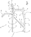
- a body structure 101 according to the second embodiment of the invention shown in FIG. figure 3 is described in the following.
- This body structure 101 has similar characteristics with the body structure 1 of the figures 1 and 2 .
- the following description is therefore centered on the differences between this second embodiment of the figure 3 and the first embodiment of figures 1 and 2 .
- the reference numbers of the figure 3 which are common with those of figures 1 and 2 refer to the same features and objects which have been described above for the first embodiment, these features and objects being found in the second embodiment.
- the cash structure 101 of the figure 3 comprises a floor 2 identical to that described above, a longitudinal slat 156 and a frame 106, which differ from the slats 56 and 58 and the frame 6 described above, in that the longitudinal slat 156 is made of material with a support element 110 of the therefore, the floor 2 is directly attached to the support member 110 by means of a S-weld by friction-fusion, the support member 110 having a longitudinal slat shaped portion 156.
- the longitudinal lath 156 has a free face 62 with a thickened portion 70, an outer edge 66 and a bearing face 60 similar to those of the first embodiment of the invention. figures 1 and 2 .
- the friction weld S of the slat 156 on the floor 2 can therefore be performed in the same way, with a similar tool, as that of the slat 56 on the floor 2 of the first embodiment.
- the outer edge 66 is optionally welded or attached to a support member, not shown, of steel alloy, of the frame 106.
- the longitudinal slat 156 is extended from a longitudinal edge 164 of the free face 62 which is opposite to the outer edge 66, by the support member 110, which protrudes upwardly from the free face.
- the floor 2 may be replaced by any aluminum alloy equipment item of the structure 1
- the stretcher 10 and the support member 110 may be replaced by any steel alloy support member of the cashier structure.
- the aluminum alloy equipment member may be a pavilion belonging to structure 1 or an intermediate decking to form an intermediate level in the case of a multi-level structure of floors.
- the steel alloy support member may be formed of a steel alloy roof, a steel alloy floor, or a steel alloy deck.
- the equipment member is attached to the support member with a single lath 56 or 58, and a single S-weld by friction-fusion.
Landscapes
- Engineering & Computer Science (AREA)
- Mechanical Engineering (AREA)
- Life Sciences & Earth Sciences (AREA)
- Wood Science & Technology (AREA)
- Pressure Welding/Diffusion-Bonding (AREA)
- Floor Finish (AREA)
- Body Structure For Vehicles (AREA)
Applications Claiming Priority (1)
| Application Number | Priority Date | Filing Date | Title |
|---|---|---|---|
| FR1660451A FR3058119B1 (fr) | 2016-10-27 | 2016-10-27 | Structure de caisse pour un vehicule sur rails et procede de fabrication d'une telle structure de caisse |
Publications (2)
| Publication Number | Publication Date |
|---|---|
| EP3315377A1 true EP3315377A1 (de) | 2018-05-02 |
| EP3315377B1 EP3315377B1 (de) | 2020-12-16 |
Family
ID=57590674
Family Applications (1)
| Application Number | Title | Priority Date | Filing Date |
|---|---|---|---|
| EP17199041.9A Active EP3315377B1 (de) | 2016-10-27 | 2017-10-27 | Karosseriestruktur für ein fahrzeug auf schienen, und herstellungsverfahren einer solchen karosseriestruktur |
Country Status (6)
| Country | Link |
|---|---|
| US (1) | US10703390B2 (de) |
| EP (1) | EP3315377B1 (de) |
| CN (1) | CN108001472B (de) |
| ES (1) | ES2857731T3 (de) |
| FR (1) | FR3058119B1 (de) |
| RU (1) | RU2743830C2 (de) |
Citations (6)
| Publication number | Priority date | Publication date | Assignee | Title |
|---|---|---|---|---|
| DE3309736A1 (de) * | 1983-03-18 | 1984-09-27 | M.A.N. Maschinenfabrik Augsburg-Nürnberg AG, 8500 Nürnberg | Untergestell fuer wagenkaesten von schienenfahrzeugen |
| FR2630698A1 (fr) * | 1988-04-29 | 1989-11-03 | Dietrich & Cie De | Structure de voiture de chemin de fer en acier et aluminium avec liaisons soudees |
| EP0392828A2 (de) * | 1989-04-14 | 1990-10-17 | Hitachi, Ltd. | Eisenbahnpersonenwagenkasten und dessen Herstellungsverfahren |
| JP2003275876A (ja) * | 2002-03-18 | 2003-09-30 | Sumitomo Light Metal Ind Ltd | 異種金属接合部材及び異種金属部材の接合方法 |
| US20050120535A1 (en) * | 2003-12-05 | 2005-06-09 | Mazda Motor Corporation | Spot joining method of metal members and spot joining apparatus of metal members |
| WO2013164294A1 (en) * | 2012-04-30 | 2013-11-07 | Universite Catholique De Louvain | Method for welding at least two layers |
Family Cites Families (9)
| Publication number | Priority date | Publication date | Assignee | Title |
|---|---|---|---|---|
| JP3070735B2 (ja) * | 1997-07-23 | 2000-07-31 | 株式会社日立製作所 | 摩擦攪拌接合方法 |
| JP2000343245A (ja) * | 1999-05-31 | 2000-12-12 | Hitachi Ltd | 構造体の製作方法 |
| US20060014009A1 (en) * | 2004-07-19 | 2006-01-19 | Kirt Weidner | Safe T flooring |
| US7178860B2 (en) * | 2005-04-22 | 2007-02-20 | Vantage Trailers, Inc. | Trailer having reduced weight wall construction |
| US20070137517A1 (en) * | 2005-12-20 | 2007-06-21 | Creighton George S | Railway Cars Manufactured With Self Piercing Rivets |
| SE530250C2 (sv) * | 2006-03-08 | 2008-04-08 | Sapa Profiler Ab | Justerbar överlappsfog och konstruktion tillverkad genom densamma |
| FR2907040B1 (fr) * | 2006-10-13 | 2009-06-26 | Alstom Transport Sa | Procede d'assemblage d'une structure comportant un exterieur et un interieur constituee d'une pluralite d'elements a double peau,telle qu'une caisse de vehicule ferroviaire,et structure obtenue. |
| US20100089977A1 (en) * | 2008-10-14 | 2010-04-15 | Gm Global Technology Operations, Inc. | Friction stir welding of dissimilar metals |
| RU158610U1 (ru) * | 2015-02-13 | 2016-01-20 | РЕЙЛ 1520 АйПи ЛТД | Вагон-хоппер |
-
2016
- 2016-10-27 FR FR1660451A patent/FR3058119B1/fr not_active Expired - Fee Related
-
2017
- 2017-10-26 RU RU2017137474A patent/RU2743830C2/ru active
- 2017-10-26 US US15/794,079 patent/US10703390B2/en active Active
- 2017-10-27 ES ES17199041T patent/ES2857731T3/es active Active
- 2017-10-27 CN CN201711027098.XA patent/CN108001472B/zh active Active
- 2017-10-27 EP EP17199041.9A patent/EP3315377B1/de active Active
Patent Citations (6)
| Publication number | Priority date | Publication date | Assignee | Title |
|---|---|---|---|---|
| DE3309736A1 (de) * | 1983-03-18 | 1984-09-27 | M.A.N. Maschinenfabrik Augsburg-Nürnberg AG, 8500 Nürnberg | Untergestell fuer wagenkaesten von schienenfahrzeugen |
| FR2630698A1 (fr) * | 1988-04-29 | 1989-11-03 | Dietrich & Cie De | Structure de voiture de chemin de fer en acier et aluminium avec liaisons soudees |
| EP0392828A2 (de) * | 1989-04-14 | 1990-10-17 | Hitachi, Ltd. | Eisenbahnpersonenwagenkasten und dessen Herstellungsverfahren |
| JP2003275876A (ja) * | 2002-03-18 | 2003-09-30 | Sumitomo Light Metal Ind Ltd | 異種金属接合部材及び異種金属部材の接合方法 |
| US20050120535A1 (en) * | 2003-12-05 | 2005-06-09 | Mazda Motor Corporation | Spot joining method of metal members and spot joining apparatus of metal members |
| WO2013164294A1 (en) * | 2012-04-30 | 2013-11-07 | Universite Catholique De Louvain | Method for welding at least two layers |
Also Published As
| Publication number | Publication date |
|---|---|
| ES2857731T3 (es) | 2021-09-29 |
| RU2017137474A (ru) | 2019-04-26 |
| RU2017137474A3 (de) | 2021-01-19 |
| CN108001472A (zh) | 2018-05-08 |
| US10703390B2 (en) | 2020-07-07 |
| EP3315377B1 (de) | 2020-12-16 |
| FR3058119B1 (fr) | 2019-01-25 |
| FR3058119A1 (fr) | 2018-05-04 |
| RU2743830C2 (ru) | 2021-02-26 |
| US20180118230A1 (en) | 2018-05-03 |
| CN108001472B (zh) | 2021-10-29 |
Similar Documents
| Publication | Publication Date | Title |
|---|---|---|
| EP1564141B1 (de) | Flugzeugsitzschiene und deren Fertigungsverfahren | |
| EP1277622B1 (de) | Kraftfahrzeugstossfänger | |
| EP3096998B1 (de) | Vorrichtung für fahrzeugkarosserieaufbau | |
| EP0285732B1 (de) | Sattelschlepperboden | |
| EP3177507B1 (de) | Fahrzeugstruktur mit verstärkung zwischen aluminiumschwelle und vorderer scharniersäule | |
| EP3083373B1 (de) | Kraftfahrzeugfassadenmodul | |
| FR2970462A1 (fr) | Pavillon de toit pour vehicule equipe de barres longitudinales de toit | |
| FR2984274A1 (fr) | Poutre securisee, en particulier cadre fort de fuselage, ainsi que fuselage d'aeronef equipe de tels cadres | |
| FR2939404A1 (fr) | Plancher modulaire pour aeronef | |
| FR2863959A1 (fr) | Glissiere pour siege de vehicule et siege de vehicule comprenant une telle glissiere | |
| EP3315377B1 (de) | Karosseriestruktur für ein fahrzeug auf schienen, und herstellungsverfahren einer solchen karosseriestruktur | |
| EP3267047A1 (de) | Vorrichtung zum zusammenbau von zwei profilen | |
| EP1819543B1 (de) | Türplattenversteifer | |
| EP3299246B1 (de) | Karosseriestruktur eines schienenfahrzeugs | |
| EP3154842B1 (de) | Vorderteil für die struktur eines kraftfahrzeugs | |
| EP3097000B1 (de) | Karosserieaufbau eines kraftfahrzeugs mit verstärkungen zur verteilung der kräfte in verbindung mit einem hinteren stossdämpfer des fahrzeugs | |
| EP2671665A1 (de) | Schutzelement für ein Fahrzeug, Fahrzeug versehen mit einem solchen Element und Verfahren zum Herstellen | |
| EP3264940B1 (de) | Schieber für schiebbare einstellungssysteme | |
| EP3505425B1 (de) | Lokale behandlung auf einschichtboden der eingänge und verteilung der belastung bei seitlichem aufprall | |
| EP3626496B1 (de) | Verstärkte sicherheitsseitentür für fahrzeug | |
| EP3950460B1 (de) | Unterboden eines fahrzeugs, entsprechendes fahrzeug und zusammenbauverfahren | |
| FR2974034A3 (fr) | Dispositif de fixation d'un element de renfort d'un ouvrant d'un vehicule automobile | |
| EP3558794B1 (de) | Fahrgestell für den fahrgastraum eines transportfahrzeugs und fahrgestellwand | |
| FR2880845A1 (fr) | Glissiere et cage a billes pour une telle glissiere | |
| BE560296A (de) |
Legal Events
| Date | Code | Title | Description |
|---|---|---|---|
| PUAI | Public reference made under article 153(3) epc to a published international application that has entered the european phase |
Free format text: ORIGINAL CODE: 0009012 |
|
| STAA | Information on the status of an ep patent application or granted ep patent |
Free format text: STATUS: THE APPLICATION HAS BEEN PUBLISHED |
|
| AK | Designated contracting states |
Kind code of ref document: A1 Designated state(s): AL AT BE BG CH CY CZ DE DK EE ES FI FR GB GR HR HU IE IS IT LI LT LU LV MC MK MT NL NO PL PT RO RS SE SI SK SM TR |
|
| AX | Request for extension of the european patent |
Extension state: BA ME |
|
| STAA | Information on the status of an ep patent application or granted ep patent |
Free format text: STATUS: REQUEST FOR EXAMINATION WAS MADE |
|
| 17P | Request for examination filed |
Effective date: 20180507 |
|
| RBV | Designated contracting states (corrected) |
Designated state(s): AL AT BE BG CH CY CZ DE DK EE ES FI FR GB GR HR HU IE IS IT LI LT LU LV MC MK MT NL NO PL PT RO RS SE SI SK SM TR |
|
| GRAP | Despatch of communication of intention to grant a patent |
Free format text: ORIGINAL CODE: EPIDOSNIGR1 |
|
| STAA | Information on the status of an ep patent application or granted ep patent |
Free format text: STATUS: GRANT OF PATENT IS INTENDED |
|
| RIC1 | Information provided on ipc code assigned before grant |
Ipc: B61D 17/04 20060101AFI20200708BHEP |
|
| INTG | Intention to grant announced |
Effective date: 20200730 |
|
| GRAS | Grant fee paid |
Free format text: ORIGINAL CODE: EPIDOSNIGR3 |
|
| GRAA | (expected) grant |
Free format text: ORIGINAL CODE: 0009210 |
|
| STAA | Information on the status of an ep patent application or granted ep patent |
Free format text: STATUS: THE PATENT HAS BEEN GRANTED |
|
| AK | Designated contracting states |
Kind code of ref document: B1 Designated state(s): AL AT BE BG CH CY CZ DE DK EE ES FI FR GB GR HR HU IE IS IT LI LT LU LV MC MK MT NL NO PL PT RO RS SE SI SK SM TR |
|
| REG | Reference to a national code |
Ref country code: GB Ref legal event code: FG4D Free format text: NOT ENGLISH |
|
| REG | Reference to a national code |
Ref country code: IE Ref legal event code: FG4D Free format text: LANGUAGE OF EP DOCUMENT: FRENCH |
|
| REG | Reference to a national code |
Ref country code: DE Ref legal event code: R096 Ref document number: 602017029545 Country of ref document: DE |
|
| REG | Reference to a national code |
Ref country code: AT Ref legal event code: REF Ref document number: 1345340 Country of ref document: AT Kind code of ref document: T Effective date: 20210115 |
|
| REG | Reference to a national code |
Ref country code: DE Ref legal event code: R082 Ref document number: 602017029545 Country of ref document: DE Representative=s name: WR SERVICES GMBH, DE |
|
| REG | Reference to a national code |
Ref country code: NL Ref legal event code: FP |
|
| PG25 | Lapsed in a contracting state [announced via postgrant information from national office to epo] |
Ref country code: GR Free format text: LAPSE BECAUSE OF FAILURE TO SUBMIT A TRANSLATION OF THE DESCRIPTION OR TO PAY THE FEE WITHIN THE PRESCRIBED TIME-LIMIT Effective date: 20210317 Ref country code: FI Free format text: LAPSE BECAUSE OF FAILURE TO SUBMIT A TRANSLATION OF THE DESCRIPTION OR TO PAY THE FEE WITHIN THE PRESCRIBED TIME-LIMIT Effective date: 20201216 Ref country code: NO Free format text: LAPSE BECAUSE OF FAILURE TO SUBMIT A TRANSLATION OF THE DESCRIPTION OR TO PAY THE FEE WITHIN THE PRESCRIBED TIME-LIMIT Effective date: 20210316 Ref country code: RS Free format text: LAPSE BECAUSE OF FAILURE TO SUBMIT A TRANSLATION OF THE DESCRIPTION OR TO PAY THE FEE WITHIN THE PRESCRIBED TIME-LIMIT Effective date: 20201216 |
|
| REG | Reference to a national code |
Ref country code: AT Ref legal event code: MK05 Ref document number: 1345340 Country of ref document: AT Kind code of ref document: T Effective date: 20201216 |
|
| PG25 | Lapsed in a contracting state [announced via postgrant information from national office to epo] |
Ref country code: BG Free format text: LAPSE BECAUSE OF FAILURE TO SUBMIT A TRANSLATION OF THE DESCRIPTION OR TO PAY THE FEE WITHIN THE PRESCRIBED TIME-LIMIT Effective date: 20210316 Ref country code: LV Free format text: LAPSE BECAUSE OF FAILURE TO SUBMIT A TRANSLATION OF THE DESCRIPTION OR TO PAY THE FEE WITHIN THE PRESCRIBED TIME-LIMIT Effective date: 20201216 Ref country code: SE Free format text: LAPSE BECAUSE OF FAILURE TO SUBMIT A TRANSLATION OF THE DESCRIPTION OR TO PAY THE FEE WITHIN THE PRESCRIBED TIME-LIMIT Effective date: 20201216 |
|
| PG25 | Lapsed in a contracting state [announced via postgrant information from national office to epo] |
Ref country code: HR Free format text: LAPSE BECAUSE OF FAILURE TO SUBMIT A TRANSLATION OF THE DESCRIPTION OR TO PAY THE FEE WITHIN THE PRESCRIBED TIME-LIMIT Effective date: 20201216 |
|
| REG | Reference to a national code |
Ref country code: LT Ref legal event code: MG9D |
|
| PG25 | Lapsed in a contracting state [announced via postgrant information from national office to epo] |
Ref country code: SM Free format text: LAPSE BECAUSE OF FAILURE TO SUBMIT A TRANSLATION OF THE DESCRIPTION OR TO PAY THE FEE WITHIN THE PRESCRIBED TIME-LIMIT Effective date: 20201216 Ref country code: LT Free format text: LAPSE BECAUSE OF FAILURE TO SUBMIT A TRANSLATION OF THE DESCRIPTION OR TO PAY THE FEE WITHIN THE PRESCRIBED TIME-LIMIT Effective date: 20201216 Ref country code: CZ Free format text: LAPSE BECAUSE OF FAILURE TO SUBMIT A TRANSLATION OF THE DESCRIPTION OR TO PAY THE FEE WITHIN THE PRESCRIBED TIME-LIMIT Effective date: 20201216 Ref country code: EE Free format text: LAPSE BECAUSE OF FAILURE TO SUBMIT A TRANSLATION OF THE DESCRIPTION OR TO PAY THE FEE WITHIN THE PRESCRIBED TIME-LIMIT Effective date: 20201216 Ref country code: RO Free format text: LAPSE BECAUSE OF FAILURE TO SUBMIT A TRANSLATION OF THE DESCRIPTION OR TO PAY THE FEE WITHIN THE PRESCRIBED TIME-LIMIT Effective date: 20201216 Ref country code: SK Free format text: LAPSE BECAUSE OF FAILURE TO SUBMIT A TRANSLATION OF THE DESCRIPTION OR TO PAY THE FEE WITHIN THE PRESCRIBED TIME-LIMIT Effective date: 20201216 Ref country code: PT Free format text: LAPSE BECAUSE OF FAILURE TO SUBMIT A TRANSLATION OF THE DESCRIPTION OR TO PAY THE FEE WITHIN THE PRESCRIBED TIME-LIMIT Effective date: 20210416 |
|
| PG25 | Lapsed in a contracting state [announced via postgrant information from national office to epo] |
Ref country code: PL Free format text: LAPSE BECAUSE OF FAILURE TO SUBMIT A TRANSLATION OF THE DESCRIPTION OR TO PAY THE FEE WITHIN THE PRESCRIBED TIME-LIMIT Effective date: 20201216 Ref country code: AT Free format text: LAPSE BECAUSE OF FAILURE TO SUBMIT A TRANSLATION OF THE DESCRIPTION OR TO PAY THE FEE WITHIN THE PRESCRIBED TIME-LIMIT Effective date: 20201216 |
|
| REG | Reference to a national code |
Ref country code: DE Ref legal event code: R097 Ref document number: 602017029545 Country of ref document: DE |
|
| REG | Reference to a national code |
Ref country code: ES Ref legal event code: FG2A Ref document number: 2857731 Country of ref document: ES Kind code of ref document: T3 Effective date: 20210929 |
|
| PG25 | Lapsed in a contracting state [announced via postgrant information from national office to epo] |
Ref country code: IS Free format text: LAPSE BECAUSE OF FAILURE TO SUBMIT A TRANSLATION OF THE DESCRIPTION OR TO PAY THE FEE WITHIN THE PRESCRIBED TIME-LIMIT Effective date: 20210416 |
|
| PLBE | No opposition filed within time limit |
Free format text: ORIGINAL CODE: 0009261 |
|
| STAA | Information on the status of an ep patent application or granted ep patent |
Free format text: STATUS: NO OPPOSITION FILED WITHIN TIME LIMIT |
|
| PG25 | Lapsed in a contracting state [announced via postgrant information from national office to epo] |
Ref country code: AL Free format text: LAPSE BECAUSE OF FAILURE TO SUBMIT A TRANSLATION OF THE DESCRIPTION OR TO PAY THE FEE WITHIN THE PRESCRIBED TIME-LIMIT Effective date: 20201216 |
|
| 26N | No opposition filed |
Effective date: 20210917 |
|
| PG25 | Lapsed in a contracting state [announced via postgrant information from national office to epo] |
Ref country code: DK Free format text: LAPSE BECAUSE OF FAILURE TO SUBMIT A TRANSLATION OF THE DESCRIPTION OR TO PAY THE FEE WITHIN THE PRESCRIBED TIME-LIMIT Effective date: 20201216 |
|
| PG25 | Lapsed in a contracting state [announced via postgrant information from national office to epo] |
Ref country code: SI Free format text: LAPSE BECAUSE OF FAILURE TO SUBMIT A TRANSLATION OF THE DESCRIPTION OR TO PAY THE FEE WITHIN THE PRESCRIBED TIME-LIMIT Effective date: 20201216 |
|
| REG | Reference to a national code |
Ref country code: CH Ref legal event code: PL |
|
| PG25 | Lapsed in a contracting state [announced via postgrant information from national office to epo] |
Ref country code: IS Free format text: LAPSE BECAUSE OF FAILURE TO SUBMIT A TRANSLATION OF THE DESCRIPTION OR TO PAY THE FEE WITHIN THE PRESCRIBED TIME-LIMIT Effective date: 20210416 |
|
| GBPC | Gb: european patent ceased through non-payment of renewal fee |
Effective date: 20211027 |
|
| PG25 | Lapsed in a contracting state [announced via postgrant information from national office to epo] |
Ref country code: MC Free format text: LAPSE BECAUSE OF FAILURE TO SUBMIT A TRANSLATION OF THE DESCRIPTION OR TO PAY THE FEE WITHIN THE PRESCRIBED TIME-LIMIT Effective date: 20201216 |
|
| PG25 | Lapsed in a contracting state [announced via postgrant information from national office to epo] |
Ref country code: LU Free format text: LAPSE BECAUSE OF NON-PAYMENT OF DUE FEES Effective date: 20211027 Ref country code: GB Free format text: LAPSE BECAUSE OF NON-PAYMENT OF DUE FEES Effective date: 20211027 |
|
| PG25 | Lapsed in a contracting state [announced via postgrant information from national office to epo] |
Ref country code: LI Free format text: LAPSE BECAUSE OF NON-PAYMENT OF DUE FEES Effective date: 20211031 Ref country code: CH Free format text: LAPSE BECAUSE OF NON-PAYMENT OF DUE FEES Effective date: 20211031 |
|
| PG25 | Lapsed in a contracting state [announced via postgrant information from national office to epo] |
Ref country code: IE Free format text: LAPSE BECAUSE OF NON-PAYMENT OF DUE FEES Effective date: 20211027 |
|
| PG25 | Lapsed in a contracting state [announced via postgrant information from national office to epo] |
Ref country code: HU Free format text: LAPSE BECAUSE OF FAILURE TO SUBMIT A TRANSLATION OF THE DESCRIPTION OR TO PAY THE FEE WITHIN THE PRESCRIBED TIME-LIMIT; INVALID AB INITIO Effective date: 20171027 |
|
| PG25 | Lapsed in a contracting state [announced via postgrant information from national office to epo] |
Ref country code: CY Free format text: LAPSE BECAUSE OF FAILURE TO SUBMIT A TRANSLATION OF THE DESCRIPTION OR TO PAY THE FEE WITHIN THE PRESCRIBED TIME-LIMIT Effective date: 20201216 |
|
| P01 | Opt-out of the competence of the unified patent court (upc) registered |
Effective date: 20230823 |
|
| PGFP | Annual fee paid to national office [announced via postgrant information from national office to epo] |
Ref country code: NL Payment date: 20231019 Year of fee payment: 7 |
|
| PGFP | Annual fee paid to national office [announced via postgrant information from national office to epo] |
Ref country code: ES Payment date: 20231227 Year of fee payment: 7 |
|
| PGFP | Annual fee paid to national office [announced via postgrant information from national office to epo] |
Ref country code: IT Payment date: 20231026 Year of fee payment: 7 Ref country code: FR Payment date: 20231026 Year of fee payment: 7 Ref country code: DE Payment date: 20231020 Year of fee payment: 7 |
|
| PGFP | Annual fee paid to national office [announced via postgrant information from national office to epo] |
Ref country code: BE Payment date: 20231019 Year of fee payment: 7 |
|
| PG25 | Lapsed in a contracting state [announced via postgrant information from national office to epo] |
Ref country code: MK Free format text: LAPSE BECAUSE OF FAILURE TO SUBMIT A TRANSLATION OF THE DESCRIPTION OR TO PAY THE FEE WITHIN THE PRESCRIBED TIME-LIMIT Effective date: 20201216 |
|
| PG25 | Lapsed in a contracting state [announced via postgrant information from national office to epo] |
Ref country code: TR Free format text: LAPSE BECAUSE OF FAILURE TO SUBMIT A TRANSLATION OF THE DESCRIPTION OR TO PAY THE FEE WITHIN THE PRESCRIBED TIME-LIMIT Effective date: 20201216 |