EP3315066A1 - Medical photometer and medical photometer control method - Google Patents
Medical photometer and medical photometer control method Download PDFInfo
- Publication number
- EP3315066A1 EP3315066A1 EP17198551.8A EP17198551A EP3315066A1 EP 3315066 A1 EP3315066 A1 EP 3315066A1 EP 17198551 A EP17198551 A EP 17198551A EP 3315066 A1 EP3315066 A1 EP 3315066A1
- Authority
- EP
- European Patent Office
- Prior art keywords
- light
- wavelength
- extinction
- light beam
- intensity
- Prior art date
- Legal status (The legal status is an assumption and is not a legal conclusion. Google has not performed a legal analysis and makes no representation as to the accuracy of the status listed.)
- Withdrawn
Links
- 238000000034 method Methods 0.000 title claims description 43
- 239000006096 absorbing agent Substances 0.000 claims abstract description 91
- 230000008033 biological extinction Effects 0.000 claims description 83
- 239000008280 blood Substances 0.000 claims description 47
- 210000004369 blood Anatomy 0.000 claims description 47
- 230000010349 pulsation Effects 0.000 claims description 13
- 210000001519 tissue Anatomy 0.000 description 44
- 108010054147 Hemoglobins Proteins 0.000 description 18
- 102000001554 Hemoglobins Human genes 0.000 description 18
- 238000005375 photometry Methods 0.000 description 17
- 230000014509 gene expression Effects 0.000 description 16
- QVGXLLKOCUKJST-UHFFFAOYSA-N atomic oxygen Chemical compound [O] QVGXLLKOCUKJST-UHFFFAOYSA-N 0.000 description 12
- 229910052760 oxygen Inorganic materials 0.000 description 12
- 239000001301 oxygen Substances 0.000 description 12
- 230000002123 temporal effect Effects 0.000 description 11
- XLYOFNOQVPJJNP-UHFFFAOYSA-N water Substances O XLYOFNOQVPJJNP-UHFFFAOYSA-N 0.000 description 11
- 230000009466 transformation Effects 0.000 description 9
- 239000000523 sample Substances 0.000 description 8
- 239000000463 material Substances 0.000 description 6
- 230000010412 perfusion Effects 0.000 description 6
- 230000003287 optical effect Effects 0.000 description 5
- 239000004065 semiconductor Substances 0.000 description 5
- 108010064719 Oxyhemoglobins Proteins 0.000 description 4
- 230000002411 adverse Effects 0.000 description 4
- 210000004204 blood vessel Anatomy 0.000 description 4
- 230000000007 visual effect Effects 0.000 description 4
- 238000001228 spectrum Methods 0.000 description 3
- 230000001133 acceleration Effects 0.000 description 2
- 230000005540 biological transmission Effects 0.000 description 2
- 230000017531 blood circulation Effects 0.000 description 2
- 238000010586 diagram Methods 0.000 description 2
- 238000005401 electroluminescence Methods 0.000 description 2
- 230000006870 function Effects 0.000 description 2
- 230000000737 periodic effect Effects 0.000 description 2
- INGWEZCOABYORO-UHFFFAOYSA-N 2-(furan-2-yl)-7-methyl-1h-1,8-naphthyridin-4-one Chemical compound N=1C2=NC(C)=CC=C2C(O)=CC=1C1=CC=CO1 INGWEZCOABYORO-UHFFFAOYSA-N 0.000 description 1
- 108010003320 Carboxyhemoglobin Proteins 0.000 description 1
- 108010061951 Methemoglobin Proteins 0.000 description 1
- 210000000577 adipose tissue Anatomy 0.000 description 1
- 230000008321 arterial blood flow Effects 0.000 description 1
- 230000000052 comparative effect Effects 0.000 description 1
- 108010002255 deoxyhemoglobin Proteins 0.000 description 1
- 210000000624 ear auricle Anatomy 0.000 description 1
- 238000012544 monitoring process Methods 0.000 description 1
- 230000035945 sensitivity Effects 0.000 description 1
- 230000008320 venous blood flow Effects 0.000 description 1
Images


Classifications
-
- A—HUMAN NECESSITIES
- A61—MEDICAL OR VETERINARY SCIENCE; HYGIENE
- A61B—DIAGNOSIS; SURGERY; IDENTIFICATION
- A61B5/00—Measuring for diagnostic purposes; Identification of persons
- A61B5/145—Measuring characteristics of blood in vivo, e.g. gas concentration, pH value; Measuring characteristics of body fluids or tissues, e.g. interstitial fluid, cerebral tissue
- A61B5/1455—Measuring characteristics of blood in vivo, e.g. gas concentration, pH value; Measuring characteristics of body fluids or tissues, e.g. interstitial fluid, cerebral tissue using optical sensors, e.g. spectral photometrical oximeters
-
- A—HUMAN NECESSITIES
- A61—MEDICAL OR VETERINARY SCIENCE; HYGIENE
- A61B—DIAGNOSIS; SURGERY; IDENTIFICATION
- A61B5/00—Measuring for diagnostic purposes; Identification of persons
- A61B5/72—Signal processing specially adapted for physiological signals or for diagnostic purposes
- A61B5/7203—Signal processing specially adapted for physiological signals or for diagnostic purposes for noise prevention, reduction or removal
- A61B5/7207—Signal processing specially adapted for physiological signals or for diagnostic purposes for noise prevention, reduction or removal of noise induced by motion artifacts
- A61B5/7214—Signal processing specially adapted for physiological signals or for diagnostic purposes for noise prevention, reduction or removal of noise induced by motion artifacts using signal cancellation, e.g. based on input of two identical physiological sensors spaced apart, or based on two signals derived from the same sensor, for different optical wavelengths
-
- A—HUMAN NECESSITIES
- A61—MEDICAL OR VETERINARY SCIENCE; HYGIENE
- A61B—DIAGNOSIS; SURGERY; IDENTIFICATION
- A61B5/00—Measuring for diagnostic purposes; Identification of persons
- A61B5/103—Detecting, measuring or recording devices for testing the shape, pattern, colour, size or movement of the body or parts thereof, for diagnostic purposes
- A61B5/107—Measuring physical dimensions, e.g. size of the entire body or parts thereof
- A61B5/1072—Measuring physical dimensions, e.g. size of the entire body or parts thereof measuring distances on the body, e.g. measuring length, height or thickness
-
- A—HUMAN NECESSITIES
- A61—MEDICAL OR VETERINARY SCIENCE; HYGIENE
- A61B—DIAGNOSIS; SURGERY; IDENTIFICATION
- A61B5/00—Measuring for diagnostic purposes; Identification of persons
- A61B5/103—Detecting, measuring or recording devices for testing the shape, pattern, colour, size or movement of the body or parts thereof, for diagnostic purposes
- A61B5/107—Measuring physical dimensions, e.g. size of the entire body or parts thereof
- A61B5/1075—Measuring physical dimensions, e.g. size of the entire body or parts thereof for measuring dimensions by non-invasive methods, e.g. for determining thickness of tissue layer
-
- A—HUMAN NECESSITIES
- A61—MEDICAL OR VETERINARY SCIENCE; HYGIENE
- A61B—DIAGNOSIS; SURGERY; IDENTIFICATION
- A61B5/00—Measuring for diagnostic purposes; Identification of persons
- A61B5/103—Detecting, measuring or recording devices for testing the shape, pattern, colour, size or movement of the body or parts thereof, for diagnostic purposes
- A61B5/107—Measuring physical dimensions, e.g. size of the entire body or parts thereof
- A61B5/1079—Measuring physical dimensions, e.g. size of the entire body or parts thereof using optical or photographic means
-
- A—HUMAN NECESSITIES
- A61—MEDICAL OR VETERINARY SCIENCE; HYGIENE
- A61B—DIAGNOSIS; SURGERY; IDENTIFICATION
- A61B5/00—Measuring for diagnostic purposes; Identification of persons
- A61B5/145—Measuring characteristics of blood in vivo, e.g. gas concentration, pH value; Measuring characteristics of body fluids or tissues, e.g. interstitial fluid, cerebral tissue
- A61B5/14542—Measuring characteristics of blood in vivo, e.g. gas concentration, pH value; Measuring characteristics of body fluids or tissues, e.g. interstitial fluid, cerebral tissue for measuring blood gases
-
- A—HUMAN NECESSITIES
- A61—MEDICAL OR VETERINARY SCIENCE; HYGIENE
- A61B—DIAGNOSIS; SURGERY; IDENTIFICATION
- A61B5/00—Measuring for diagnostic purposes; Identification of persons
- A61B5/145—Measuring characteristics of blood in vivo, e.g. gas concentration, pH value; Measuring characteristics of body fluids or tissues, e.g. interstitial fluid, cerebral tissue
- A61B5/1455—Measuring characteristics of blood in vivo, e.g. gas concentration, pH value; Measuring characteristics of body fluids or tissues, e.g. interstitial fluid, cerebral tissue using optical sensors, e.g. spectral photometrical oximeters
- A61B5/14551—Measuring characteristics of blood in vivo, e.g. gas concentration, pH value; Measuring characteristics of body fluids or tissues, e.g. interstitial fluid, cerebral tissue using optical sensors, e.g. spectral photometrical oximeters for measuring blood gases
-
- G—PHYSICS
- G01—MEASURING; TESTING
- G01N—INVESTIGATING OR ANALYSING MATERIALS BY DETERMINING THEIR CHEMICAL OR PHYSICAL PROPERTIES
- G01N21/00—Investigating or analysing materials by the use of optical means, i.e. using sub-millimetre waves, infrared, visible or ultraviolet light
- G01N21/17—Systems in which incident light is modified in accordance with the properties of the material investigated
- G01N21/25—Colour; Spectral properties, i.e. comparison of effect of material on the light at two or more different wavelengths or wavelength bands
- G01N21/27—Colour; Spectral properties, i.e. comparison of effect of material on the light at two or more different wavelengths or wavelength bands using photo-electric detection ; circuits for computing concentration
-
- G—PHYSICS
- G01—MEASURING; TESTING
- G01N—INVESTIGATING OR ANALYSING MATERIALS BY DETERMINING THEIR CHEMICAL OR PHYSICAL PROPERTIES
- G01N21/00—Investigating or analysing materials by the use of optical means, i.e. using sub-millimetre waves, infrared, visible or ultraviolet light
- G01N21/17—Systems in which incident light is modified in accordance with the properties of the material investigated
- G01N21/59—Transmissivity
-
- A—HUMAN NECESSITIES
- A61—MEDICAL OR VETERINARY SCIENCE; HYGIENE
- A61B—DIAGNOSIS; SURGERY; IDENTIFICATION
- A61B2562/00—Details of sensors; Constructional details of sensor housings or probes; Accessories for sensors
- A61B2562/02—Details of sensors specially adapted for in-vivo measurements
- A61B2562/0233—Special features of optical sensors or probes classified in A61B5/00
- A61B2562/0238—Optical sensor arrangements for performing transmission measurements on body tissue
-
- G—PHYSICS
- G01—MEASURING; TESTING
- G01J—MEASUREMENT OF INTENSITY, VELOCITY, SPECTRAL CONTENT, POLARISATION, PHASE OR PULSE CHARACTERISTICS OF INFRARED, VISIBLE OR ULTRAVIOLET LIGHT; COLORIMETRY; RADIATION PYROMETRY
- G01J1/00—Photometry, e.g. photographic exposure meter
- G01J1/02—Details
- G01J1/04—Optical or mechanical part supplementary adjustable parts
-
- G—PHYSICS
- G01—MEASURING; TESTING
- G01N—INVESTIGATING OR ANALYSING MATERIALS BY DETERMINING THEIR CHEMICAL OR PHYSICAL PROPERTIES
- G01N21/00—Investigating or analysing materials by the use of optical means, i.e. using sub-millimetre waves, infrared, visible or ultraviolet light
- G01N21/17—Systems in which incident light is modified in accordance with the properties of the material investigated
- G01N21/25—Colour; Spectral properties, i.e. comparison of effect of material on the light at two or more different wavelengths or wavelength bands
- G01N21/31—Investigating relative effect of material at wavelengths characteristic of specific elements or molecules, e.g. atomic absorption spectrometry
- G01N21/314—Investigating relative effect of material at wavelengths characteristic of specific elements or molecules, e.g. atomic absorption spectrometry with comparison of measurements at specific and non-specific wavelengths
Definitions
- the present invention relates to a medical photometer which calculates the amount of a material having a relatively low extinction in the body of the subject, and also to a method of controlling a medical photometer for calculating the amount of the material.
- a pulse photometer that is an example of a medical photometer is an apparatus which calculates the concentration of a blood light absorber of the subject as an example of photometry.
- the living tissue of the subject is irradiated with light beams at a plurality of wavelengths at which ratios of the blood extinction coefficients are different from each other depending on the blood light absorber concentration.
- the intensities of the light beams at the wavelengths transmitted through or reflected from the living tissue are detected.
- the intensities at the wavelengths are varied in accordance with the pulsation of the blood in the subject. Therefore, due to the pulsation, temporal variations of the intensities at the wavelengths are acquired in the form of a pulse wave signal.
- the amplitudes of pulse wave signals with respect to wavelengths correspond to light attenuation variations with respect to the same wavelengths.
- the blood light absorber concentration is calculated based on a ratio of light attenuation variations with respect to wavelengths (for example, see Japanese Patent No. 4,196,209 ).
- a medical photometer includes:
- a medical photometer includes:
- a method of controlling a medical photometer includes:
- the amount of a weak light absorber in body can be calculated.
- Fig. 1 is a diagram illustrating the functional configuration of a medical photometer 10 of a first embodiment.
- the medical photometer 10 is an apparatus which calculates the amount of a weak light absorber in the living body 20.
- the medical photometer 10 may include a first light emitter 11, a second light emitter 12, a detector 14, an interface 15, and a controller 16.
- the first light emitter 11 is configured so as to emit a first light beam having a first wavelength ⁇ 1 .
- the second light emitter 12 is configured so as to emit a second light beam having a second wavelength ⁇ 2 .
- An example of the first wavelength ⁇ 1 is 880 nm.
- An example of the second wavelength ⁇ 2 is 940 nm. Namely, both the first and second light beams are infrared light beams.
- the first light emitter 11 is a semiconductor light emitting device which can emit the first light beam.
- the second light emitter 12 is a semiconductor light emitting device which can emit the second light beam. Examples of such a semiconductor light emitting device are a light emitting diode (LED), a laser diode, and an organic electroluminescence element.
- LED light emitting diode
- laser diode a laser diode
- organic electroluminescence element organic electroluminescence element
- the detector 14 is configured so as to output a first intensity signal in accordance with the intensity I 1 of the first light beam that is transmitted through or reflected from a tissue of a living body 20 (the finger or ear lobe of the subject).
- the detector 14 is further configured so as to output a second intensity signal in accordance with the intensity I 2 of the second light beam that is transmitted through or reflected from the living body 20.
- the detector 14 is an optical sensor having a sensitivity to the first wavelength ⁇ 1 and the second wavelength ⁇ 2 . Examples of the optical sensor are a photodiode, a phototransistor, and a photoresistor.
- the first light emitter 11, the second light emitter 12, and the detector 14 are connected to the interface 15.
- the interface 15 is a connector which allows signals to pass therethrough.
- the connection may be realized as wired or wireless connection.
- the controller 16 is communicably connected to the first light emitter 11, the second light emitter 12, and the detector 14 through the interface 15. Therefore, the controller 16 can control the operations of the first light emitter 11 and the second light emitter 12 through the interface 15.
- the controller 16 can receive the first and second intensity signals from the detector 14 through the interface 15.
- the controller 16 may include a processor 61 and a memory 62.
- Examples of the processor 61 are a CPU and an MPU.
- the memory 62 is configured so as to store an instruction that is readable by a computer.
- Examples of the memory 62 are a ROM which stores various instructions, and a RAM having a work area in which various instructions are executed by the processor 61.
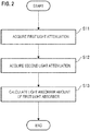
- the medical photometer 10 is configured so as to execute the process shown in Fig. 2 when an instruction stored in the memory 62 is executed by the processor 61.
- a light attenuation (first light attenuation) A 1 of the first light beam that is transmitted through or reflected from the living body 20 is acquired based on the first intensity signal supplied from the detector 14 (step S11).
- a light attenuation (second light attenuation) A 2 of the second light beam that is transmitted through or reflected from the living body 20 is acquired based on the second intensity signal supplied from the detector 14 (step S12).
- Steps S11 and S12 may be performed in parallel, or step S12 may be performed in advance of step S11.
- the amount of the weak light absorber in the tissue of the living body 20 which the first and second light beams are transmitted through or reflected from is calculated based on the first and second light attenuations A 1 and A 2 which are acquired as described above (step S13).
- the solid line indicates the extinction spectrum of water (an example of the first light absorber)
- the broken line indicates the extinction spectrum of deoxyhemoglobin
- the dash-dot line indicates the extinction spectrum of oxyhemoglobin (an example of the second light absorber).
- the extinction (an example of the first extinction) of water at the first wavelength ⁇ 1 of the first light beam, and the extinction (an example of the second extinction) of water at the second wavelength ⁇ 2 of the second light beam are different from each other.
- a ratio of the extinction of water at the first wavelength ⁇ 1 and that of water at the second wavelength ⁇ 2 is different from 1.
- the term "different from 1" means that the ratio has a value of 2 or larger, or 0.5 or smaller.
- the extinction (an example of the third extinction) of hemoglobin at the first wavelength ⁇ 1 of the first light beam is higher than that of water at the same wavelength.
- the extinction (an example of the fourth extinction) of hemoglobin at the second wavelength ⁇ 2 of the second light beam is higher than that of water at the same wavelength.
- the extinction of water is lower than that of hemoglobin at the first and second wavelengths ⁇ 1 and ⁇ 2 .
- water is an example of the weak light absorber in body.
- the extinction of hemoglobin at the first wavelength ⁇ 1 and that of hemoglobin at the second wavelength ⁇ 2 are substantially equal to each other.
- a ratio of the extinction of hemoglobin at the first wavelength ⁇ 1 and that of hemoglobin at the second wavelength ⁇ 2 can be approximated by 1.
- the term "can be approximated by 1" means that the ratio has a value smaller than 2 or larger than 0.5.
- the first and second wavelengths ⁇ 1 and ⁇ 2 are selected so that a weak light absorber in body (the first light absorber) the amount of which is to be specified has substantially different extinctions at ⁇ 1 and ⁇ 2 , and that a light absorber (the second light absorber) which is higher in extinction than the weak light absorber in body shows substantially equal extinctions at ⁇ 1 and ⁇ 2 .
- the above-described second light attenuation A 2 is the sum of the contribution of the light attenuation due to the first light absorber at the second wavelength ⁇ 2 , and that of contribution of the light attenuation due to the second light absorber, and can be indicated by the following expression:
- a 2 E 12 C 1 D 1 + E 22 C 2 D 2
- E 21 indicates the extinction coefficient (M -1 cm -1 ) of the first light absorber at the second wavelength ⁇ 2
- E 22 indicates the extinction coefficient (M -1 cm -1 ) of the second light absorber at the second wavelength ⁇ 2 .
- the contribution of the light attenuation due to the second light absorber at the first wavelength ⁇ 1 , and that of the light attenuation due to the second light absorber at the second wavelength ⁇ 2 are substantially equal to each other.
- the contribution of the light attenuation due to the second light absorber can be neglected, and only the contribution of the light attenuation due to the first light absorber can be extracted.
- the second term of the left side is a ratio of the intensity of the first light beam emitted from the first light emitter 11, and that of the second light beam emitted from the second light emitter 12. As described above, these values are already known, and therefore the second term of the left side can be treated as a constant.
- E 11 and E 21 in the right side are constants. Therefore, C 1 D 1 can be specified from a ratio of the detected intensity of the first light beam by the detector 14, and that of the second light beam. This value corresponds to the amount of the first light absorber, i.e., the weak light absorber in body.
- the amount of the weak light absorber in body can be calculated even with the principle of photometry.
- the first light attenuation A 1 can be indicated more specifically by following expression as the sum of the contribution of the light attenuation due to the arterial blood at the first wavelength ⁇ 1 , that of the light attenuation due to the venous blood, and that of the light attenuation due to tissues other than the blood:
- a 1 E a 1 HbD a + E v 1 HbD v + ⁇ t 1 D t
- E a1 indicates the extinction coefficient (dl g -1 cm -1 ) of hemoglobin in arterial blood at the first wavelength ⁇ 1
- Hb indicates the hemoglobin concentration in blood (dl g -1 )
- D a indicates the thickness (cm) of the blood vessel through which the arterial blood flows
- E v1 indicates the extinction coefficient (dl g -1 cm -1 ) of hemoglobin in venous blood at the first wavelength ⁇ 1
- D a indicates the thickness (cm) of the blood vessel through which the arterial blood flows
- the second light attenuation A 2 can be indicated by the following expression as the sum of the contribution of the light attenuation due to the arterial blood at the second wavelength ⁇ 2 , that of the light attenuation due to the venous blood, and that of contribution of the light attenuation due to tissues other than the blood, and can be indicated by the following expression:
- a 2 E a 2 HbD a + E v 2 HbD v + ⁇ t 2 D t
- E a2 indicates the extinction coefficient (dl g -1 cm -1 ) of hemoglobin in arterial blood at the second wavelength ⁇ 2
- E v2 indicates the extinction coefficient (dl g -1 cm -1 ) of hemoglobin in venous blood at the second wavelength ⁇ 2
- ⁇ t2 indicates the light attenuation rate (cm -1 ) due to tissues other than the blood at the second wavelength ⁇ 2 .
- the contribution of the light attenuation due to hemoglobin at the first wavelength ⁇ 1 , and that of the light attenuation due to hemoglobin at the second wavelength ⁇ 2 are substantially equal to each other.
- the difference between the first light attenuation A 1 and the second light attenuation A 2 is obtained, therefore, the contribution of the light attenuation due to hemoglobin can be neglected, and only the contribution of the light attenuation due to the tissue thickness Dt can be extracted.
- the second term of the left side is a ratio of the intensity of the first light beam emitted from the first light emitter 11, and that of the second light beam emitted from the second light emitter 12. As described above, these values are already known, and therefore the second term of the left side can be treated as a constant. On the other hand, also ⁇ t1 and ⁇ t2 in the right side are constants. Therefore, the tissue thickness D t can be specified from a ratio of the detected intensity of the first light beam by the detector 14, and that of the second light beam.
- the perfusion index As an index indicating the degree of the blood circulation, the perfusion index is known. Even when the blood vessel pulsates at the same expansion rate, different perfusion indices may be acquired with photometry depending on the difference in tissue thickness. In the case of a subject having large fingers (the tissue thickness is large), the perfusion index generally tends to have a large value. In other words, when attention is focused only on the fact that the value of the perfusion index is small, it is not possible to accurately distinguish whether the fact is caused by insufficient perfusion of blood or by a small tissue thickness.
- the tissue thickness of the living body 20 can be specified with the principle of photometry, and therefore it is possible to provide information which can compensate insufficient information named the perfusion index. Consequently, the degree of the blood circulation in the living body 20 can be determined more accurately
- the medical photometer 10 may include a third light emitter 13.
- the third light emitter 13 is configured so as to emit a third light beam having a third wavelength ⁇ 3 .
- an example of the third wavelength ⁇ 3 is 660 nm.
- the third light emitter 13 is a semiconductor light emitting device which can emit the third light beam. Examples of such a semiconductor light emitting device are a light emitting diode (LED), a laser diode, and an organic electroluminescence element.
- the third wavelength ⁇ 3 is selected as a wavelength which satisfies the following conditions.
- the detector 14 is configured so as to output a third intensity signal in accordance with the intensity I 3 of the third light beam that is transmitted through or reflected from the tissue of the living body 20.
- the third light emitter 13 is connected to the interface 15.
- the connection may be realized as wired or wireless connection.
- the controller 16 is communicably connected to the third light emitter 13 through the interface 15. Therefore, the controller 16 can control the operation of the third light emitter 13 through the interface 15.
- the controller 16 can receive the third intensity signal from the detector 14 through the interface 15.
- the medical photometer 10 acquires a light attenuation variation ⁇ A 3 of the third light beam due to the blood pulsation in the tissue (the place where the first and second light attenuations A 1 and A 2 are acquired) of the living body 20 based on the third intensity signal and at least one of the first and second intensity signals supplied from the detector 14.
- a ratio of oxyhemoglobin to the amount of hemoglobin capable of carrying oxygen in the arterial blood i.e., the arterial oxygen saturation (an example of the concentration of the second light absorber) is calculated based on the light attenuation variation ⁇ A 3 of the third light beam and at least one of the acquired light attenuation variations ⁇ A 1 and ⁇ A 2 of the first and second light beams.
- the arterial oxygen saturation an example of the concentration of the second light absorber
- the arterial oxygen saturation can be calculated with the principle of so-called pulse photometry. That is, the above-described configuration for specifying the amount of the weak light absorber in body can be integrated into a conventional probe which is to be used in pulse photometry. Namely, the user is allowed to easily calculate the amount of the weak light absorber in body and the arterial oxygen saturation, by simply attaching the probe to the tissue of the living body 20.
- step S21 the first light attenuation A 1 due to transmission through or reflection from the living body 20 is acquired based on the first intensity signal supplied from the detector 14 (step S21).
- step S22 the second light attenuation A 2 due to transmission through or reflection from the living body 20 is acquired based on the second intensity signal supplied from the detector 14 (step S22).
- Steps S21 and S22 may be performed in parallel, or step S22 may be performed in advance of step S21.
- the tissue thickness Dt of the living body 20 which the first and second light beams are transmitted through or reflected from is calculated based on the first and second light attenuations A 1 and A 2 that are acquired as described above (step S23).
- the calculation of the tissue thickness Dt is performed with Expressions (6) to (8) which have been described with reference to step S13 in Fig. 2 .
- step S24 an artifact of the living body 20 is detected based on a variation ⁇ D 1 of the tissue thickness Dt which is calculated in step S23 (step S24).
- the tissue thickness Dt of the interested living body 20 is varied by an artifact of the living body 20.
- Expression (8) for obtaining the tissue thickness Dt can be transformed into the following manner.
- the value (I 2 /I 1 ) in Expression (8) i.e., the intensity ratio of the first and second light beams detected by the detector 14 is expressed as R
- the value (I 02 /I 01 ) in Expression (8) i.e., the intensity ratio of the light beams emitted from the first and second light emitters 11 and 12 is expressed as Ro.
- the controller 16 monitors the temporal variation of the tissue thickness Dt by observing the temporal variation of the intensity ratio R of the first and second light beams detected by the detector 14.
- a variation ⁇ R occurs in the intensity ratio R, it can be deemed that ⁇ D t is caused also in the tissue thickness Dt.
- the lower left graph in Fig. 6 illustrates a temporal variation of the intensity I 1 of the first light beam detected by the detector 14.
- the left half of the graph illustrates a rest state, and the right half illustrates a state where a large artifact is intentionally induced. It is seen that the intensity I1 is periodically varied also in the rest state. The periodic variation is due to pulsation of the living body 20.
- the upper left graph in Fig. 6 illustrates a temporal variation of the intensity ratio R of the first and second light beams detected by the detector 14.
- the left half of the graph illustrates a rest state, and the right half illustrates a state where a large artifact is intentionally induced.
- the periodic variation of the intensity ratio due to pulsation is suppressed in the rest state.
- the detector 14 detects a temporal variation of the intensity ratio R of the first and second light beams which corresponds to a temporal variation of the tissue thickness Dt, a variation of the detected intensity due to pulsation can be cancelled out, and a variation of the detected intensity due to an artifact can be more clearly extracted. This is because pulsation does not have a substantial influence on the tissue thickness Dt.
- the tissue thickness of a living body can be calculated with the principle of photometry, and moreover an artifact of the living body which is one of factors affecting the photometry can be accurately detected.
- step S25 it is determined whether the whole process is to be ended or not. If it is determined that the whole process is to be ended (YES in step S25), the whole process is ended. If it is determined that the whole process is not to be ended (NO in step S25), the process of detecting an artifact (step S24) is repeated.
- the medical photometer 10 of the embodiment may include a notifying section 17.
- the notifying section 17 is configured so as to perform notification when the degree of the detected artifact exceeds a predetermined value.
- the notification is performed by at least one of visual notification and auditory notification.
- the medical photometer 10 is configured so as to perform the processes indicated by the broken line in Fig. 4 when an instruction stored in the memory 62 is executed by the processor 61.
- step S24 it is determined whether the degree of the artifact exceeds the predetermined value or not (step S26).
- the predetermined value is adequately adjustable by the user. Specifically, it is determined whether the variation rate of the intensity ratio R which is indicated in the upper left graph in Fig. 6 exceeds the predetermined value or not. A situation where the conditions are continued to be satisfied for a predetermined period of time may be added to criteria for the determination.
- step S26 If it is determined that the degree of the detected artifact exceeds the predetermined value (YES in step S26), the notification is performed (step S27). As described above, the notification can be performed by at least one of visual notification and auditory notification. After the notification, the process is transferred to step S25, and the above-described processes are repeated.
- step S26 If it is determined that the degree of the detected artifact is equal to or smaller than the predetermined value (NO in step S26), the process is transferred to step S25, and the above-described processes are repeated.
- the user is notified of an artifact of the living body 20 which may disturb the operation of the medical photometer 10, and thereby the user can take adequate procedures.
- the predetermined value is properly set, it is possible to notify of only a situation where procedures must be truly taken. This can prevent the working efficiency of the user from being lowered.
- the first light emitter 11, the second light emitter 12, and the detector 14 can be integrated into a conventional pulse photometry probe including the third light emitter 13.
- an independent sensor such as an acceleration sensor
- a configuration for calculating the tissue thickness can be integrated into a probe for calculating the arterial oxygen saturation, and moreover an artifact can be detected with the probe. Therefore, a situation where an artifact has an adverse influence on a calculated result of the arterial oxygen saturation can be avoided without adding an independent sensor.
- the intensity of the first intensity signal corresponding to the intensity I 1 of the first light beam which is emitted from the first light emitter 11 and detected by the detector 14 is acquired (step S31).
- step S32 the intensity of the second intensity signal corresponding to the intensity I 2 of the second light beam which is emitted from the second light emitter 12 and detected by the detector 14 is acquired.
- Steps S31 and S32 may be performed in parallel, or step S32 may be performed in advance of step S31.
- an intensity ratio which is a ratio of the intensity of the first intensity signal acquired in step S31, and that of the second intensity signal acquired in step S32 is obtained (step S33).
- the first wavelength ⁇ 1 and the second wavelength ⁇ 2 must be selected so as to enable the tissue thickness Dt to be calculated.
- the calculation of the tissue thickness Dt which has been described in the second embodiment is not essential.
- an artifact of the living body which is one of factors affecting the photometry can be accurately detected even with the principle of photometry.
- step S35 it is determined whether the whole process is to be ended or not. If it is determined that the whole process is to be ended (YES in step S35), the whole process is ended. If it is determined that the whole process is not to be ended (NO in step S35), the process of detecting an artifact (step S34) is repeated.
- a coordinate plane P1 shown in the right half in Fig. 6 is used.
- the abscissa of the coordinate plane P1 indicates the variation rate of the intensity of the first or second intensity signal. Namely, the abscissa of the coordinate plane P1 corresponds to the variation rate of the intensity I 1 of the first light beam detected by the detector 14, or that of the intensity I 2 of the second light beam (in the illustrated example, the abscissa corresponds to the variation rate of the intensity I 1 of the first light beam).
- the ordinate of the coordinate plane P1 indicates the variation rate of the intensity ratio of the first and second intensity signals. Namely, the ordinate of the coordinate plane P1 corresponds to the variation rate of the intensity ratio R of the first and second light beams detected by the detector 14.
- an artifact of the living body 20 can be detected based on a temporal variation of a point in the coordinate plane P1, i.e., the shape of a locus (Lissajous figure) drawn by the point.
- the upper right graph in Fig. 6 illustrates a Lissajous figure L1a in the rest state. Since there is no artifact, the Lissajous figure L1a does not have a substantial width in the direction of the ordinate. Only the temporal variation of the first intensity signal due to pulsation is reflected in the Lissajous figure L1a, and the figure has a substantial width in only the direction along the abscissa.
- the lower right graph in Fig. 6 illustrates a Lissajous figure L1b in the state where a large artifact is intentionally induced.
- the intensity ratio R of the first and second light beams is largely varied, and therefore the Lissajous figure L1b has a substantial width in the direction of the ordinate.
- the fact that the Lissajous figure on the coordinate plane P1 has a substantial width in the direction of the ordinate suggests the existence of an artifact of the living body 20.
- Such a Lissajous figure on the coordinate plane P1 can be displayed on a displaying section which is not shown.
- the user can more intuitively recognize an existence of an artifact.
- the medical photometer 10 can execute a process of reducing an artifact component from an acquired signal (step S36) when an instruction stored in the memory 62 is executed by the processor 61.
- a coordinate transformation from the coordinate plane P1 to a coordinate plane P2 is performed.
- the abscissa of the coordinate plane P2 indicates a component (signal component) S which is a component of an acquired intensity signal (in the example, the first intensity signal), and to which the pulsation of the living body 20 contributes.
- the ordinate of the coordinate plane P2 indicates a component (noise component) N which is a component of the acquired intensity signal, and to which an artifact of the living body 20 contributes.
- the Lissajous figure L1b which is formed in accordance with the artifact has a substantial width in both the directions of the abscissa and the ordinate. Therefore, the Lissajous figure L1b has a slope ⁇ to the abscissa on the coordinate plane P1. In other words, the slope ⁇ is an angle between the abscissa and the N axis corresponding to the noise component of the Lissajous figure L1b.
- the coordinate transformation is performed so as to make the direction of the slope ⁇ to coincide with the ordinate of the coordinate plane P2.
- a Lissajous figure L2 is obtained on the coordinate plane P2.
- the pulsation-contributed component and artifact-contributed component in the acquired first intensity signal are clearly separated from each other.
- the artifact-contributed component can be reduced from the first intensity signal, and only the pulsation-contributed component can be extracted.
- the slope ⁇ in the coordinate plane P1 is determined by searching the value in the range from 0 to ⁇ /2, and by specifying a value at which the norm in the S-axis direction in the coordinate plane P2 is minimum.
- the intensity of the second intensity signal is selected as the abscissa of the coordinate plane, and similar processes are performed, whereby only the pulsation-contributed component of the acquired second intensity signal can be extracted.
- Fig. 7B diagrammatically illustrates a reduction method of an artifact component in a conventional pulse oximeter, as a comparative example.
- a coordinate plane P0 is used in the technique.
- the abscissa of the coordinate plane P0 corresponds to the variation rate of the intensity of a first light beam detected by a detector.
- the ordinate of the coordinate plane P0 corresponds to the variation rate of the intensity of a second light beam detected by the detector.
- the first and second light beams in this method are used for calculating the blood light absorber concentration, and different from those in the embodiments for calculating the amount of a weak light absorber in body.
- a Lissajous figure L0 is formed in the thus configured coordinate plane P0.
- an S axis corresponding to the pulsation-contributed component (signal component), and an N axis corresponding to the artifact-contributed component (noise component) can be defined in the Lissajous figure L0.
- an angle ⁇ between the S axis and the abscissa in the coordinate plane P0 must be specified.
- information of the blood light absorber concentration is required both because the blood light absorber concentration is indicated as a function of the extinction ratio of the first and second light beams and because the extinction ratio is indicated as a function of the angle ⁇ .
- an angle ⁇ between the S axis and the N axis in the coordinate plane P0 must be specified.
- An angle ⁇ between the N axis and the abscissa in the coordinate plane P0 is determined by searching the value of ⁇ in the range from - ⁇ to ( ⁇ /2 - ⁇ ), and by specifying a value at which the norm in the S-axis direction in the coordinate plane P2 is minimum.
- An angle ⁇ is obtained by subtract ⁇ from angle ⁇ .
- the medical photometer 10 of the embodiment may include the notifying section 17.
- the notifying section 17 is configured so as to perform notification when the degree of the detected artifact exceeds a predetermined value.
- the notification is performed by at least one of visual notification and auditory notification.
- the medical photometer 10 is configured so as to perform the processes indicated by the broken line in Fig. 5 when an instruction stored in the memory 62 is executed by the processor 61.
- step S34 it is determined whether the degree of the artifact exceeds the predetermined value or not (step S37).
- the predetermined value is adequately adjustable by the user. Specifically, it is determined whether the width in the direction along the ordinate of the Lissajous figure L1b shown in Fig. 6 exceeds the predetermined value or not. A situation where the conditions are continued to be satisfied for a predetermined period of time may be added to criteria for the determination.
- step S38 the notification is performed.
- the notification can be performed by at least one of visual notification and auditory notification. After the notification, the process is transferred to step S35, and the above-described processes are repeated.
- step S37 If it is determined that the degree of the detected artifact is equal to or smaller than the predetermined value (NO in step S37), the process is transferred to step S36, and the above-described processes are repeated.
- the user is notified of an artifact of the living body 20 which may disturb the operation of the medical photometer 10, and thereby the user can take adequate procedures.
- the predetermined value is properly set, it is possible to notify of only a situation where procedures must be truly taken. This can prevent the working efficiency of the user from being lowered.
- the first light emitter 11, the second light emitter 12, and the detector 14 can be integrated into a conventional pulse photometry probe including the third light emitter 13.
- an independent sensor such as an acceleration sensor
- a configuration for calculating the tissue thickness can be integrated into a probe for calculating the arterial oxygen saturation, and moreover an artifact can be detected with the probe. Therefore, a situation where an artifact has an adverse influence on a calculated result of the arterial oxygen saturation can be avoided without adding an independent sensor.
- both the first light beam emitted from the first light emitter 11, and the second light beam emitted from the second light emitter 12 are infrared light beams.
- a configuration where both the first and second light beams are red light beams may be employed.
- conditions are that the extinction of the weak light absorber in body at the first wavelength ⁇ 1 of the first light beam, and that of the weak light absorber in body at the second wavelength ⁇ 2 of the second light beam are substantially different from each other, and that a material which is higher in extinction than the weak light absorber in body has substantially equal extinctions at the first wavelength ⁇ 1 and the second wavelength ⁇ 2 .
- light beams of 700 nm and 730 nm may be selected as the first and second light beams.
- the arterial oxygen saturation is used as an example of the blood light absorber concentration.
- the invention can be applied also to a configuration for calculating the concentration of another blood light absorber.
- another blood light absorber are carboxyhemoglobin, methemoglobin, and a dye injected into blood vessels.
- the wavelengths of the light beams are selected so that a ratio of the extinction coefficient of blood at these wavelengths is varied depending on the concentration of the target light absorber contained in the blood.
- the variation rate (I1 or I2) of the intensity of the first or second intensity signal is selected as the abscissa of the coordinate plane P1
- the variation rate (R) of the intensity ratio of the first and second intensity signals is selected as the ordinate.
- the abscissa indicates the signal component (S)
- the ordinate indicates the noise component (N).
- the variation rate (I1 or I2) of the intensity of the first or second intensity signal may be selected as the ordinate of the coordinate plane P1
- the variation rate (R) of the intensity ratio of the first and second intensity signals may be selected as the abscissa.
- the ordinate indicates the signal component (S)
- the abscissa indicates the noise component (N).
Landscapes
- Health & Medical Sciences (AREA)
- Life Sciences & Earth Sciences (AREA)
- Physics & Mathematics (AREA)
- Engineering & Computer Science (AREA)
- General Health & Medical Sciences (AREA)
- Pathology (AREA)
- Biophysics (AREA)
- Veterinary Medicine (AREA)
- Public Health (AREA)
- Animal Behavior & Ethology (AREA)
- Biomedical Technology (AREA)
- Heart & Thoracic Surgery (AREA)
- Medical Informatics (AREA)
- Molecular Biology (AREA)
- Surgery (AREA)
- Dentistry (AREA)
- Oral & Maxillofacial Surgery (AREA)
- Optics & Photonics (AREA)
- Spectroscopy & Molecular Physics (AREA)
- Signal Processing (AREA)
- Immunology (AREA)
- General Physics & Mathematics (AREA)
- Biochemistry (AREA)
- Analytical Chemistry (AREA)
- Chemical & Material Sciences (AREA)
- Artificial Intelligence (AREA)
- Computer Vision & Pattern Recognition (AREA)
- Physiology (AREA)
- Psychiatry (AREA)
- Mathematical Physics (AREA)
- Theoretical Computer Science (AREA)
- Measurement Of The Respiration, Hearing Ability, Form, And Blood Characteristics Of Living Organisms (AREA)
Applications Claiming Priority (1)
| Application Number | Priority Date | Filing Date | Title |
|---|---|---|---|
| JP2016211012A JP6847627B2 (ja) | 2016-10-27 | 2016-10-27 | 医用フォトメータ、および医用フォトメータの制御方法 |
Publications (1)
| Publication Number | Publication Date |
|---|---|
| EP3315066A1 true EP3315066A1 (en) | 2018-05-02 |
Family
ID=60191156
Family Applications (1)
| Application Number | Title | Priority Date | Filing Date |
|---|---|---|---|
| EP17198551.8A Withdrawn EP3315066A1 (en) | 2016-10-27 | 2017-10-26 | Medical photometer and medical photometer control method |
Country Status (3)
| Country | Link |
|---|---|
| US (1) | US10342465B2 (ja) |
| EP (1) | EP3315066A1 (ja) |
| JP (1) | JP6847627B2 (ja) |
Families Citing this family (2)
| Publication number | Priority date | Publication date | Assignee | Title |
|---|---|---|---|---|
| JP6857484B2 (ja) * | 2016-10-27 | 2021-04-14 | 日本光電工業株式会社 | 医用フォトメータ、および医用フォトメータの制御方法 |
| JP6794219B2 (ja) * | 2016-10-27 | 2020-12-02 | 日本光電工業株式会社 | 医用フォトメータ、および医用フォトメータの制御方法 |
Citations (4)
| Publication number | Priority date | Publication date | Assignee | Title |
|---|---|---|---|---|
| US20030009090A1 (en) * | 2001-04-19 | 2003-01-09 | Jeon Kye-Jin | Method and apparatus for noninvasively monitoring hemoglobin concentration and oxygen saturation |
| US20050065415A1 (en) * | 2003-09-24 | 2005-03-24 | Ok-Kyung Cho | Optical measurement apparatus and blood sugar level measuring apparatus using the same |
| JP4196209B2 (ja) | 2003-06-30 | 2008-12-17 | 日本光電工業株式会社 | 信号処理方法及びそれを適用したパルスフォトメータ |
| US20140247274A1 (en) * | 2013-03-04 | 2014-09-04 | Nihon Kohden Corporation | Display apparatus |
Family Cites Families (7)
| Publication number | Priority date | Publication date | Assignee | Title |
|---|---|---|---|---|
| US4805623A (en) * | 1987-09-04 | 1989-02-21 | Vander Corporation | Spectrophotometric method for quantitatively determining the concentration of a dilute component in a light- or other radiation-scattering environment |
| US5284137A (en) * | 1988-07-26 | 1994-02-08 | Manfred Kessler | Process and device for the determination of local dye concentrations and of scattering parameters in animal and human tissues |
| JPH10216112A (ja) * | 1997-02-04 | 1998-08-18 | Hitachi Ltd | 無侵襲生化学計測装置 |
| US6002952A (en) * | 1997-04-14 | 1999-12-14 | Masimo Corporation | Signal processing apparatus and method |
| US7025728B2 (en) | 2003-06-30 | 2006-04-11 | Nihon Kohden Corporation | Method for reducing noise, and pulse photometer using the method |
| WO2013165887A1 (en) * | 2012-04-30 | 2013-11-07 | Mayo Foundation For Medical Education And Research | Method and apparatus for selecting wavelengths for optimal measurement of a property of a molecular analyte |
| JP6385865B2 (ja) * | 2014-03-28 | 2018-09-05 | 日本光電工業株式会社 | パルスフォトメータ |
-
2016
- 2016-10-27 JP JP2016211012A patent/JP6847627B2/ja active Active
-
2017
- 2017-10-25 US US15/793,371 patent/US10342465B2/en active Active
- 2017-10-26 EP EP17198551.8A patent/EP3315066A1/en not_active Withdrawn
Patent Citations (4)
| Publication number | Priority date | Publication date | Assignee | Title |
|---|---|---|---|---|
| US20030009090A1 (en) * | 2001-04-19 | 2003-01-09 | Jeon Kye-Jin | Method and apparatus for noninvasively monitoring hemoglobin concentration and oxygen saturation |
| JP4196209B2 (ja) | 2003-06-30 | 2008-12-17 | 日本光電工業株式会社 | 信号処理方法及びそれを適用したパルスフォトメータ |
| US20050065415A1 (en) * | 2003-09-24 | 2005-03-24 | Ok-Kyung Cho | Optical measurement apparatus and blood sugar level measuring apparatus using the same |
| US20140247274A1 (en) * | 2013-03-04 | 2014-09-04 | Nihon Kohden Corporation | Display apparatus |
Also Published As
| Publication number | Publication date |
|---|---|
| US10342465B2 (en) | 2019-07-09 |
| US20180116569A1 (en) | 2018-05-03 |
| JP6847627B2 (ja) | 2021-03-24 |
| JP2018068573A (ja) | 2018-05-10 |
Similar Documents
| Publication | Publication Date | Title |
|---|---|---|
| US11647923B2 (en) | Tissue profile wellness monitor | |
| US9801584B2 (en) | Method for detection of aberrant tissue spectra | |
| US20120165629A1 (en) | Systems and methods of monitoring a patient through frequency-domain photo migration spectroscopy | |
| US10702196B2 (en) | Pulse photometer | |
| US10117611B2 (en) | Biological signal measuring system and biological signal measuring apparatus | |
| EP3315070B1 (en) | Medical photometer and medical photometer control method | |
| EP3315066A1 (en) | Medical photometer and medical photometer control method | |
| US10722154B2 (en) | Medical photometer and medical photometer control method | |
| CN114224335A (zh) | 一种多光电探测器并联的血氧检测方法及装置 | |
| EP3459458A1 (en) | Medical photometer and medical photometry system | |
| EP3135198B1 (en) | Pulse photometer and method for evaluating reliability of calculated value of blood light absorber concentration | |
| US11331046B2 (en) | Pulse oximeter | |
| EP3117763B1 (en) | Probe | |
| EP3064137B1 (en) | Pulse photometer and method for calculating concentration of light absorber in blood | |
| McEwen et al. | Noninvasive monitoring with strongly absorbed light | |
| US20230048928A1 (en) | Pulse oximeter, pulse oximetry system, processing device, and pulse oximetry method |
Legal Events
| Date | Code | Title | Description |
|---|---|---|---|
| PUAI | Public reference made under article 153(3) epc to a published international application that has entered the european phase |
Free format text: ORIGINAL CODE: 0009012 |
|
| AK | Designated contracting states |
Kind code of ref document: A1 Designated state(s): AL AT BE BG CH CY CZ DE DK EE ES FI FR GB GR HR HU IE IS IT LI LT LU LV MC MK MT NL NO PL PT RO RS SE SI SK SM TR |
|
| AX | Request for extension of the european patent |
Extension state: BA ME |
|
| STAA | Information on the status of an ep patent application or granted ep patent |
Free format text: STATUS: THE APPLICATION IS DEEMED TO BE WITHDRAWN |
|
| 18D | Application deemed to be withdrawn |
Effective date: 20181103 |