EP3314318B1 - Ensemble fibres de distribution - Google Patents
Ensemble fibres de distribution Download PDFInfo
- Publication number
- EP3314318B1 EP3314318B1 EP16813773.5A EP16813773A EP3314318B1 EP 3314318 B1 EP3314318 B1 EP 3314318B1 EP 16813773 A EP16813773 A EP 16813773A EP 3314318 B1 EP3314318 B1 EP 3314318B1
- Authority
- EP
- European Patent Office
- Prior art keywords
- delivery
- fiber
- delivery fiber
- inclusions
- light
- Prior art date
- Legal status (The legal status is an assumption and is not a legal conclusion. Google has not performed a legal analysis and makes no representation as to the accuracy of the status listed.)
- Active
Links
- 239000000835 fiber Substances 0.000 title claims description 421
- 230000005540 biological transmission Effects 0.000 claims description 79
- 238000005253 cladding Methods 0.000 claims description 75
- 239000013307 optical fiber Substances 0.000 claims description 43
- 239000000463 material Substances 0.000 claims description 28
- 239000007787 solid Substances 0.000 claims description 28
- VYPSYNLAJGMNEJ-UHFFFAOYSA-N Silicium dioxide Chemical group O=[Si]=O VYPSYNLAJGMNEJ-UHFFFAOYSA-N 0.000 claims description 22
- 239000011343 solid material Substances 0.000 claims description 15
- 239000000377 silicon dioxide Substances 0.000 claims description 11
- 230000003287 optical effect Effects 0.000 description 47
- 235000021251 pulses Nutrition 0.000 description 41
- 230000003595 spectral effect Effects 0.000 description 24
- 238000005286 illumination Methods 0.000 description 13
- 230000008878 coupling Effects 0.000 description 11
- 238000010168 coupling process Methods 0.000 description 11
- 238000005859 coupling reaction Methods 0.000 description 11
- 238000001228 spectrum Methods 0.000 description 9
- 230000010287 polarization Effects 0.000 description 8
- 238000000034 method Methods 0.000 description 7
- 238000012014 optical coherence tomography Methods 0.000 description 7
- 239000004065 semiconductor Substances 0.000 description 7
- 230000005855 radiation Effects 0.000 description 6
- 238000004611 spectroscopical analysis Methods 0.000 description 6
- 239000000758 substrate Substances 0.000 description 6
- 229910052796 boron Inorganic materials 0.000 description 5
- 229910052731 fluorine Inorganic materials 0.000 description 5
- 230000013011 mating Effects 0.000 description 5
- ZOXJGFHDIHLPTG-UHFFFAOYSA-N Boron Chemical compound [B] ZOXJGFHDIHLPTG-UHFFFAOYSA-N 0.000 description 4
- 238000005452 bending Methods 0.000 description 4
- 238000004519 manufacturing process Methods 0.000 description 4
- 238000000429 assembly Methods 0.000 description 3
- 230000000712 assembly Effects 0.000 description 3
- 230000008901 benefit Effects 0.000 description 3
- 230000005284 excitation Effects 0.000 description 3
- 239000011521 glass Substances 0.000 description 3
- 238000003384 imaging method Methods 0.000 description 3
- 238000000386 microscopy Methods 0.000 description 3
- 238000001356 surgical procedure Methods 0.000 description 3
- PXGOKWXKJXAPGV-UHFFFAOYSA-N Fluorine Chemical compound FF PXGOKWXKJXAPGV-UHFFFAOYSA-N 0.000 description 2
- 101100456571 Mus musculus Med12 gene Proteins 0.000 description 2
- 239000011248 coating agent Substances 0.000 description 2
- 238000000576 coating method Methods 0.000 description 2
- 238000009826 distribution Methods 0.000 description 2
- 238000000799 fluorescence microscopy Methods 0.000 description 2
- 238000002866 fluorescence resonance energy transfer Methods 0.000 description 2
- 239000011737 fluorine Substances 0.000 description 2
- 238000007689 inspection Methods 0.000 description 2
- 239000000203 mixture Substances 0.000 description 2
- 238000000059 patterning Methods 0.000 description 2
- 239000004038 photonic crystal Substances 0.000 description 2
- 235000010627 Phaseolus vulgaris Nutrition 0.000 description 1
- 244000046052 Phaseolus vulgaris Species 0.000 description 1
- 238000010521 absorption reaction Methods 0.000 description 1
- 230000004913 activation Effects 0.000 description 1
- 230000002730 additional effect Effects 0.000 description 1
- 238000004458 analytical method Methods 0.000 description 1
- 230000009286 beneficial effect Effects 0.000 description 1
- 230000008859 change Effects 0.000 description 1
- 238000004140 cleaning Methods 0.000 description 1
- 238000002052 colonoscopy Methods 0.000 description 1
- 238000006880 cross-coupling reaction Methods 0.000 description 1
- 239000013078 crystal Substances 0.000 description 1
- 230000003111 delayed effect Effects 0.000 description 1
- 238000001514 detection method Methods 0.000 description 1
- 238000002059 diagnostic imaging Methods 0.000 description 1
- 239000006185 dispersion Substances 0.000 description 1
- 235000013399 edible fruits Nutrition 0.000 description 1
- 238000001839 endoscopy Methods 0.000 description 1
- 238000001914 filtration Methods 0.000 description 1
- 238000000684 flow cytometry Methods 0.000 description 1
- 230000004927 fusion Effects 0.000 description 1
- 229910052732 germanium Inorganic materials 0.000 description 1
- 238000007726 management method Methods 0.000 description 1
- 238000005259 measurement Methods 0.000 description 1
- 238000013208 measuring procedure Methods 0.000 description 1
- 230000007246 mechanism Effects 0.000 description 1
- 238000012986 modification Methods 0.000 description 1
- 230000004048 modification Effects 0.000 description 1
- 229910052698 phosphorus Inorganic materials 0.000 description 1
- 238000005498 polishing Methods 0.000 description 1
- 229920000642 polymer Polymers 0.000 description 1
- 230000008569 process Effects 0.000 description 1
- 230000001902 propagating effect Effects 0.000 description 1
- 238000002165 resonance energy transfer Methods 0.000 description 1
- 238000007493 shaping process Methods 0.000 description 1
- 239000000126 substance Substances 0.000 description 1
- 238000012360 testing method Methods 0.000 description 1
- 239000010409 thin film Substances 0.000 description 1
- 238000001161 time-correlated single photon counting Methods 0.000 description 1
- 238000012546 transfer Methods 0.000 description 1
- 238000012800 visualization Methods 0.000 description 1
- XLYOFNOQVPJJNP-UHFFFAOYSA-N water Substances O XLYOFNOQVPJJNP-UHFFFAOYSA-N 0.000 description 1
Images


Classifications
-
- G—PHYSICS
- G02—OPTICS
- G02B—OPTICAL ELEMENTS, SYSTEMS OR APPARATUS
- G02B21/00—Microscopes
- G02B21/0004—Microscopes specially adapted for specific applications
- G02B21/002—Scanning microscopes
- G02B21/0024—Confocal scanning microscopes (CSOMs) or confocal "macroscopes"; Accessories which are not restricted to use with CSOMs, e.g. sample holders
- G02B21/0032—Optical details of illumination, e.g. light-sources, pinholes, beam splitters, slits, fibers
-
- G—PHYSICS
- G02—OPTICS
- G02B—OPTICAL ELEMENTS, SYSTEMS OR APPARATUS
- G02B6/00—Light guides; Structural details of arrangements comprising light guides and other optical elements, e.g. couplings
- G02B6/02—Optical fibres with cladding with or without a coating
- G02B6/02295—Microstructured optical fibre
- G02B6/02314—Plurality of longitudinal structures extending along optical fibre axis, e.g. holes
- G02B6/02342—Plurality of longitudinal structures extending along optical fibre axis, e.g. holes characterised by cladding features, i.e. light confining region
- G02B6/02347—Longitudinal structures arranged to form a regular periodic lattice, e.g. triangular, square, honeycomb unit cell repeated throughout cladding
-
- G—PHYSICS
- G02—OPTICS
- G02B—OPTICAL ELEMENTS, SYSTEMS OR APPARATUS
- G02B6/00—Light guides; Structural details of arrangements comprising light guides and other optical elements, e.g. couplings
- G02B6/02—Optical fibres with cladding with or without a coating
- G02B6/02295—Microstructured optical fibre
- G02B6/02314—Plurality of longitudinal structures extending along optical fibre axis, e.g. holes
- G02B6/02342—Plurality of longitudinal structures extending along optical fibre axis, e.g. holes characterised by cladding features, i.e. light confining region
- G02B6/02357—Property of longitudinal structures or background material varies radially and/or azimuthally in the cladding, e.g. size, spacing, periodicity, shape, refractive index, graded index, quasiperiodic, quasicrystals
-
- A—HUMAN NECESSITIES
- A61—MEDICAL OR VETERINARY SCIENCE; HYGIENE
- A61B—DIAGNOSIS; SURGERY; IDENTIFICATION
- A61B1/00—Instruments for performing medical examinations of the interior of cavities or tubes of the body by visual or photographical inspection, e.g. endoscopes; Illuminating arrangements therefor
- A61B1/06—Instruments for performing medical examinations of the interior of cavities or tubes of the body by visual or photographical inspection, e.g. endoscopes; Illuminating arrangements therefor with illuminating arrangements
- A61B1/07—Instruments for performing medical examinations of the interior of cavities or tubes of the body by visual or photographical inspection, e.g. endoscopes; Illuminating arrangements therefor with illuminating arrangements using light-conductive means, e.g. optical fibres
-
- A—HUMAN NECESSITIES
- A61—MEDICAL OR VETERINARY SCIENCE; HYGIENE
- A61B—DIAGNOSIS; SURGERY; IDENTIFICATION
- A61B5/00—Measuring for diagnostic purposes; Identification of persons
- A61B5/0059—Measuring for diagnostic purposes; Identification of persons using light, e.g. diagnosis by transillumination, diascopy, fluorescence
- A61B5/0062—Arrangements for scanning
- A61B5/0066—Optical coherence imaging
-
- G—PHYSICS
- G01—MEASURING; TESTING
- G01B—MEASURING LENGTH, THICKNESS OR SIMILAR LINEAR DIMENSIONS; MEASURING ANGLES; MEASURING AREAS; MEASURING IRREGULARITIES OF SURFACES OR CONTOURS
- G01B9/00—Measuring instruments characterised by the use of optical techniques
- G01B9/02—Interferometers
- G01B9/0209—Low-coherence interferometers
- G01B9/02091—Tomographic interferometers, e.g. based on optical coherence
-
- G—PHYSICS
- G02—OPTICS
- G02B—OPTICAL ELEMENTS, SYSTEMS OR APPARATUS
- G02B23/00—Telescopes, e.g. binoculars; Periscopes; Instruments for viewing the inside of hollow bodies; Viewfinders; Optical aiming or sighting devices
- G02B23/24—Instruments or systems for viewing the inside of hollow bodies, e.g. fibrescopes
- G02B23/2407—Optical details
- G02B23/2461—Illumination
- G02B23/2469—Illumination using optical fibres
-
- G—PHYSICS
- G02—OPTICS
- G02B—OPTICAL ELEMENTS, SYSTEMS OR APPARATUS
- G02B6/00—Light guides; Structural details of arrangements comprising light guides and other optical elements, e.g. couplings
- G02B6/02—Optical fibres with cladding with or without a coating
- G02B6/02295—Microstructured optical fibre
- G02B6/02314—Plurality of longitudinal structures extending along optical fibre axis, e.g. holes
- G02B6/02342—Plurality of longitudinal structures extending along optical fibre axis, e.g. holes characterised by cladding features, i.e. light confining region
- G02B6/02361—Longitudinal structures forming multiple layers around the core, e.g. arranged in multiple rings with each ring having longitudinal elements at substantially the same radial distance from the core, having rotational symmetry about the fibre axis
-
- G—PHYSICS
- G02—OPTICS
- G02B—OPTICAL ELEMENTS, SYSTEMS OR APPARATUS
- G02B6/00—Light guides; Structural details of arrangements comprising light guides and other optical elements, e.g. couplings
- G02B6/02—Optical fibres with cladding with or without a coating
- G02B6/024—Optical fibres with cladding with or without a coating with polarisation maintaining properties
-
- G—PHYSICS
- G02—OPTICS
- G02B—OPTICAL ELEMENTS, SYSTEMS OR APPARATUS
- G02B6/00—Light guides; Structural details of arrangements comprising light guides and other optical elements, e.g. couplings
- G02B6/24—Coupling light guides
- G02B6/26—Optical coupling means
- G02B6/28—Optical coupling means having data bus means, i.e. plural waveguides interconnected and providing an inherently bidirectional system by mixing and splitting signals
- G02B6/2804—Optical coupling means having data bus means, i.e. plural waveguides interconnected and providing an inherently bidirectional system by mixing and splitting signals forming multipart couplers without wavelength selective elements, e.g. "T" couplers, star couplers
- G02B6/2821—Optical coupling means having data bus means, i.e. plural waveguides interconnected and providing an inherently bidirectional system by mixing and splitting signals forming multipart couplers without wavelength selective elements, e.g. "T" couplers, star couplers using lateral coupling between contiguous fibres to split or combine optical signals
-
- G—PHYSICS
- G02—OPTICS
- G02B—OPTICAL ELEMENTS, SYSTEMS OR APPARATUS
- G02B6/00—Light guides; Structural details of arrangements comprising light guides and other optical elements, e.g. couplings
- G02B6/24—Coupling light guides
- G02B6/26—Optical coupling means
- G02B6/28—Optical coupling means having data bus means, i.e. plural waveguides interconnected and providing an inherently bidirectional system by mixing and splitting signals
- G02B6/293—Optical coupling means having data bus means, i.e. plural waveguides interconnected and providing an inherently bidirectional system by mixing and splitting signals with wavelength selective means
- G02B6/29379—Optical coupling means having data bus means, i.e. plural waveguides interconnected and providing an inherently bidirectional system by mixing and splitting signals with wavelength selective means characterised by the function or use of the complete device
- G02B6/2938—Optical coupling means having data bus means, i.e. plural waveguides interconnected and providing an inherently bidirectional system by mixing and splitting signals with wavelength selective means characterised by the function or use of the complete device for multiplexing or demultiplexing, i.e. combining or separating wavelengths, e.g. 1xN, NxM
-
- G—PHYSICS
- G02—OPTICS
- G02B—OPTICAL ELEMENTS, SYSTEMS OR APPARATUS
- G02B6/00—Light guides; Structural details of arrangements comprising light guides and other optical elements, e.g. couplings
- G02B6/24—Coupling light guides
- G02B6/26—Optical coupling means
- G02B6/28—Optical coupling means having data bus means, i.e. plural waveguides interconnected and providing an inherently bidirectional system by mixing and splitting signals
- G02B6/293—Optical coupling means having data bus means, i.e. plural waveguides interconnected and providing an inherently bidirectional system by mixing and splitting signals with wavelength selective means
- G02B6/29379—Optical coupling means having data bus means, i.e. plural waveguides interconnected and providing an inherently bidirectional system by mixing and splitting signals with wavelength selective means characterised by the function or use of the complete device
- G02B6/29389—Bandpass filtering, e.g. 1x1 device rejecting or passing certain wavelengths
-
- H—ELECTRICITY
- H01—ELECTRIC ELEMENTS
- H01S—DEVICES USING THE PROCESS OF LIGHT AMPLIFICATION BY STIMULATED EMISSION OF RADIATION [LASER] TO AMPLIFY OR GENERATE LIGHT; DEVICES USING STIMULATED EMISSION OF ELECTROMAGNETIC RADIATION IN WAVE RANGES OTHER THAN OPTICAL
- H01S3/00—Lasers, i.e. devices using stimulated emission of electromagnetic radiation in the infrared, visible or ultraviolet wave range
- H01S3/23—Arrangements of two or more lasers not provided for in groups H01S3/02 - H01S3/22, e.g. tandem arrangements of separate active media
- H01S3/2308—Amplifier arrangements, e.g. MOPA
Definitions
- the invention relates to a delivery fiber suitable for delivering light from a broad band source.
- WO15003714 discloses a supercontinuum light source comprising a microstructured optical fiber and a pump light source, where the microstructured optical fiber comprises an intermediate tapered section. Thereby a very broad and stable supercontinuum of light is obtained.
- US 8,731,009 discloses a super continuum light source comprising a pump source and a generator fiber for generating the supercontinuum, where the refractive index profile of the core of the generator fiber is arranged to allow modal cleaning of the light as it propagates to provide an optical super continuum with relatively high spectral density and/or good beam quality.
- the generated light or fractions thereof are often used in high precision illumination procedures and/or high precision measuring procedures such as for stimulated emission depletion, for fluorescence imaging procedures for Optical Coherence Tomography (OCT) and/or for industrial inspection, such as metrology.
- high precision illumination procedures and/or high precision measuring procedures such as for stimulated emission depletion, for fluorescence imaging procedures for Optical Coherence Tomography (OCT) and/or for industrial inspection, such as metrology.
- OCT Optical Coherence Tomography
- the light or fractions of light generated by the broad band source is transmitted via a delivery fiber to an apparatus, such as an illumination apparatus and/or a measuring apparatus for use in the measuring process of the apparatus.
- an apparatus such as an illumination apparatus and/or a measuring apparatus for use in the measuring process of the apparatus.
- the delivery fiber is simple to connect to the apparatus and it is well known in the art to use standard connectors such as connectors according to the standards IEC 61754-20, IEC 61754-15 or IEC 61754-13.
- the prior art delivery fibers have usually been step index fibers having a relatively very narrow transmission band with because such fibers are easy to handle, easy to connectorize and have low transmission loss.
- step index fibers having a relatively very narrow transmission band with because such fibers are easy to handle, easy to connectorize and have low transmission loss.
- PCF photonic crystal fiber
- In order to be capable of transmitting a broader band width is has been suggested to use of photonic crystal fiber (PCF) with air holes in their cross-sections as delivery fiber has been introduced; thereby the delivery fiber is capable of transmitting a broader band width.
- PCF photonic crystal fiber
- such holey PCF generally is difficult to connect and may result in undesired power loss.
- JP2011107687 describes an optical fiber which eliminates the need for hole control and a special connection step during manufacture.
- WO2004019092 describes an improved large mode area, single mode or few mode optical fibre that is robust towards low mechanisms such as bending losses and coupling losses.
- the conference proceedings article “ Polarization maintaining hybrid TIR / bandgap all-solid photonic crystal fiber", Lyngso J K et al., Lasers and Electro-Optics, 2008 . CLEO 2008, discloses a polarization maintaining microstructured optical fiber with solid inclusions.
- An object of the present invention is to provide a delivery fiber assembly suitable for delivering broad band light from a broad band source and/or from two or more sources as well as a broad band source system where the delivery fiber is simple to connect to an apparatus for transmitting light to the apparatus and where at least one of the problems discussed above is alleviated.
- a delivery fiber assembly according to claim 1 is provided. It is further an object to provide a broad band source and a broad band source system comprising a delivery fiber which is simple to connect e.g. to an apparatus for transmitting light to the apparatus and where at least one of the problems discussed above is alleviated.
- the novel delivery fiber assembly has a relatively high mechanical strength, which in fact is highly beneficial because such delivery fibers usually are subjected to mechanical disturbances such as bends and rough handling. Often the delivery is coiled and uncoiled repeatedly and with no control of coiling diameter.
- the delivery fiber assembly of the invention is adapted for delivering broad band light to an apparatus for transmitting light to the apparatus.
- the delivery fiber assembly comprises a delivery fiber and a connector member.
- the delivery fiber has a length, an input end for launching light and a delivery end for delivering light.
- the delivery fiber comprises along its length a core region and a cladding region surrounding the core region wherein the cladding region comprises a cladding background material having a refractive index N bg and a plurality of microstructures in the form of inclusions of solid material having refractive index of up to N inc and extending in the length of and preferably along the longitudinal axis of the delivery fiber, wherein N inc ⁇ N bg .
- the plurality of inclusions in the cladding region is arranged in a cross-sectional pattern (a pattern seen in a cross section of the delivery fiber) comprising at least two rings of inclusions surrounding the core region.
- the connector member is mounted to the delivery fiber at a delivery end section of the delivery fiber comprising the delivery end.
- the delivery fiber has a transmission bandwidth of about 200 nm or more, such as of about 300 nm or more, such as of about 400 nm or more, such as of about 500 nm or more for example at least an octave (halving/doubling in frequency).
- the core region has a diameter up to about 15 ⁇ m
- the transmission bandwidth is defined as the wavelengths where the delivery fiber has a transmission loss of less than 0.5 dB/m.
- the transmission bandwidth is defined as the wavelengths where the delivery fiber has a transmission loss of than less than 0.1 dB/m.
- the transmission loss is measured when the fiber is bend with either a 16 cm or a 32 cm bending diameter.
- an all solid fiber comprising solid inclusions as delivery fiber for delivering light from a broad band source to an apparatus for measurement and/or illumination.
- such all solid fiber comprising solid inclusions could be constructed to have a transmission bandwidth of 200 nm or larger and in particular it is surprising that the all solid fiber comprising solid inclusions can be constructed to have a transmission bandwidth of 200 nm or less, below 1800 nm or even below 900 nm.
- inclusions means inclusions in a background material, wherein an inclusion has another refractive index than that of the background material surrounding it.
- the solid inclusions can for example be inclusions of another glass type than the background material and/or an inclusion of doped material (index changing materials such as F, Ge, P, B,) or any combinations thereof.
- the inclusions of a delivery fiber can be of equal or different material or structure.
- An inclusion may be of a homogeneous material or it may have regions of different materials and/or refractive index. Where an inclusion comprises several regions of different refractive index the refractive index of the inclusion is determined as the average refractive index of the inclusion.
- ring of inclusions refers to the cladding inclusions typically having substantially equal radial distance to the core and being aligned in a ring configuration surrounding the core.
- a ring of inclusions is not fully circular, but rather is shaped with a number of soft angles, such as in a hexagonal shape.
- all the inclusions of a ring of inclusions are of substantially the same size and preferably of same material.
- radial distance means distance determined in radial direction from the longitudinal axis of the core of the delivery fiber.
- the diameter of the core and of an inclusion is determined as the characteristic diameter of the core/ inclusion.
- the core or the inclusions are not always entirely circular.
- the characteristic diameter is the diameter of the circle of the inclusion/core where it is circular or in case the inclusion is not circular, the characteristic diameter is determined as the average of the maximum and the minimum extent of the inclusion/core in question.
- the delivery end section of the delivery fiber comprising the delivery end, and the connector member is mounted at a mounting distance from the delivery end such that the delivery end is passing through the connector member for connecting the delivery end in physical contact with a receiver waveguide, preferably a receiver fiber, such as a receiver fiber incorporated in an apparatus for illumination and/or metrology and/or surgery.
- the delivery end of the fiber is the end facet.
- the mounting distance to the delivery end is usually a few mm e.g. at least 2 mm, such as up to 2 cm or preferably less than 1 cm.
- the mounting distance to the delivery end is usually given by the structure of the connector member.
- the connector member is a standard connector member such as a standard connector member according to at least one of the standards IEC 61754-20, IEC 61754-15 or IEC 61754-13 or equivalent standards.
- the mounting distance from the delivery end is determined as the distance from the delivery end to the nearest physical contact to the connector member.
- the connector member has a connecting flange that extends beyond the delivery end for being mated with and connected to another connector member while simultaneously protecting the connected delivery end.
- the delivery end Prior to being connected to the apparatus the delivery end is desirably protected by a removable cap.
- the delivery end is advantageously polished and optionally arranged to have a facet which is angled e.g. up to 60 degrees, such as up to about 30 degrees, such as from about 3 to 10 degrees, such as about 8 degrees relative to the cross-section plan of the fiber so as to reduce undesired reflection of light at the end facet.
- the angle of the facet is often selected as a compromise.
- the facet angle should advantageously not be too large because that may result in an undesired angular dispersion.
- the delivery end section of the delivery fiber is mounted to the connector member such that the delivery end of the delivery fiber is suitable for connectorisation, without changing the fiber waveguide structure.
- the delivery fiber of the delivery fiber assembly can be connected to an apparatus without the use of free space optics - i.e. without the transmission at the connection site is outside the fiber - and without undesired change of the phase front of the propagating mode. Further the delivery fiber of the delivery fiber assembly can be connected to an apparatus without undesired expansion of mode field and thereby loss of light can be reduced or entirely avoided.
- the connector member is mounted to the delivery fiber at the delivery end section of the delivery fiber at a distance to the delivery end, such that the delivery end is passing through the connector member for connecting the delivery end in physical contact with a receiver waveguide, preferably a receiver fiber, such as a receiver fiber incorporated in an apparatus for illumination and/or metrology and/or surgery.
- the connector member preferably comprises a ferrule and the delivery end section passes through the ferrule for being coupled to the receiver unit.
- the connector member is arranged such that the delivery end can be brought in physical contact with and connected to a receiving waveguide e.g. an optical fiber comprising a corresponding receiving waveguide connector member.
- a receiving waveguide e.g. an optical fiber comprising a corresponding receiving waveguide connector member.
- the connector member is spring-loaded, so the delivery end facet can be mated to a receiving fiber in a butt coupling where fiber faces are pressed together when the connectors are mated.
- the resulting glass-to-glass contact eliminates signal losses that would be caused by an air gap between the joined fibers.
- the delivery fiber has, at least along its delivery end section and optionally along the entire length of the fiber, a constant mode field diameter for at least one wavelength within the transmission bandwidth where the mode field is expanding the fiber may lose light.
- the delivery end section preferably comprises a length of the fiber of at least 2 mm, preferably at least about 5 mm, such as at least 1 cm.
- the delivery fiber has a constant mode field diameter to wavelength profile within the transmission bandwidth at least along the delivery end section.
- the phrase 'mode field diameter to wavelength profile' means the profile of the respective mode field diameters relative to the respective wavelengths within the transmission bandwidth.
- the mode field diameters of the delivery fiber are advantageously selected in dependence on the desired transmission wavelength bandwidth. It has been found that the mode field diameter for a wavelength range of wavelengths below 2 ⁇ m varies surprisingly little. Thus for a bandwidth of 100 nm the mode field diameter varies preferably less than 10 % based on the mode field diameter of the lowest wavelength.
- the relatively small core region i.e. about 15 ⁇ m or smaller is an important factor for keeping the mode field diameter range for the transmission bandwidth narrow.
- the mode field diameter range for the transmission bandwidth may be even narrower.
- the mode field diameter variation is smaller for wavelength of about 900 nm or less than for larger wavelengths.
- the delivery fiber may be tailored by selecting a mode field diameter range i.e.
- the delivery fiber at least along said delivery end section has a mode field diameter range for said transmission wavelength, wherein the mode field diameter range is about 30 % or less, such as about 20% or less, such than about 15 % or less, such as about 10 % or less of the lowest mode field diameter of the range.
- the mode field diameter range is the range of mode field diameters corresponding to the transmission band width and the lowest mode field diameter of the range is the mode field diameter of the lowest wavelength of the transmission band width.
- the delivery fiber for at least one wavelength within said transmission bandwidth and at least along said delivery end section has a constant numerical aperture NA and a propagation loss less than 0.5 dB/m, such as less than about 0.2 dB/m, such as less than about 0.1 dB/m or even less than 0.05 dB/m.
- the delivery fiber is single mode for at least one wavelength within the transmission bandwidth.
- the beam of light has a much higher quality for single mode light than for multimode light and for some applications single mode light is a requirement.
- the delivery fiber is single mode for at least about 50 %, such as at least about 80 % of the transmission bandwidth, such as for the entire transmission bandwidth of the delivery fiber.
- the delivery fiber is a polarization-maintaining optical fiber (PM fiber).
- the PM fiber may for example comprise one or more stress elements.
- a PM fiber is a fiber in which linear polarization can be maintained if linearly polarized light is launched into the fiber.
- the launched polarized light maintains a linear polarization during propagation along the PM delivery fiber and exits the fiber in a linear polarization state.
- the PM delivery fiber is single-mode for at least one wavelength within the transmission bandwidth.
- the PM properties can for example be induced by incorporating stress elements e.g. such as described in US 7,289,709 .
- the core region may in principle have any core diameter depending on the power and the wavelengths to be transmitted.
- the delivery fiber core region has a diameter of at least about 3 ⁇ m.
- the core region may vary along the length of the delivery fiber, but generally it is preferred that the core region has a substantially identical diameter along the major part of the delivery fiber, such as preferably along at least about 80 % of the length of the delivery fiber.
- core region diameters are up to about 15 ⁇ m, such as within the range of from about 3 ⁇ m to about 10 ⁇ m, such as from about 4 ⁇ m to about 12 ⁇ m.
- the delivery fiber core region advantageously has a diameter of less than about 10 ⁇ m because it has been found that where the core region of the delivery fiber is larger, such as larger than about 15 nm, there is an increased loss in the UV light region. All structural details of the optical fiber, such as core region size, inclusion diameters and pattern are given in relation to a cross-sectional view of the fiber unless otherwise specified.
- the plurality of inclusions in the cladding region is arranged in a cross-sectional pattern comprising at least four rings of inclusions surrounding the core region, such as at least five rings of inclusions surrounding the core region. It has been found that by increasing the number of rings of inclusion the transmission bandwidth can be increased and further additional properties, such as single mode properties and/or reduced loss can be enhanced.
- the rings of inclusions are advantageously arranged in a pitch pattern such that the distance between adjacent inclusions is P times the pitch, where P is 0.5 or an integer up to five, preferably up to 3, such as 1 or 2, and where P can have different value from different distances of nearest inclusions.
- the inclusions are arranged in a pitch pattern, a double pitch pattern, a triple pitch pattern, a half pitch pattern or a combination thereof, where a pitch is determined as the smallest center to center distance between the core region and an inclusion.
- the pitch ⁇ can be used in tailoring the delivery fiber for a desired transmission band width and in particularly whether or not the transmission band width comprises wavelength in the blue range below 450 nm and/or in the red range above 800 nm.
- the pitch is less than about 10 ⁇ m, preferably less than about 9 ⁇ m, such as less than about 8 ⁇ m, such as less than about 7 ⁇ m, such as less than about 6 ⁇ m.
- the pitch is advantageously about 3.2 ⁇ m or larger, such as about 3.2 ⁇ m or larger, such as about 4 ⁇ m or larger, such as about 5 ⁇ m or larger, such as about 5 ⁇ m or larger, such as about 7 ⁇ m or larger, such as about 8 ⁇ m or larger.
- the core region diameter to pitch d/ ⁇ may advantageously be about 0.7 or less, such as from about 0.3 to about 0.65, such as from about 0.4 to about 0.6.
- the core region has a refractive index N core
- the cladding region has an effective refractive index N clad
- the refractive index N bg of the cladding background material is substantially identical to the refractive index of the core region N core .
- the refractive index of the core region is homogeneous.
- the core region is microstructured e.g., as described in co-pending DK PA 2014 00545 . Where the core region is microstructured the refractive index of the core region Ncore is determined as the average refractive index.
- the refractive index N bg of the cladding background material differs from the refractive index of the core region N core , preferably such that the refractive index N bg of the cladding background material is lower than the refractive index of the core region N core .
- the delivery fiber is a silica fiber and the solid inclusions are of down doped silica.
- the solid inclusions independently of each other are silica doped with at least one of fluorine and/or boron and/or component comprising F and/or B atoms.
- the respective inclusions may have equal or different refractive indices and an inclusion may have several regions with different refractive indices in which situation the refractive index is determined as the average refractive index as described above.
- the difference between refractive indices of the respective inclusions independent from each other and the refractive index of the background material N bg is from about 10 -5 to about 0.1, such as from about 10 -4 to about 10 -2 , such as up to about 10 -3 .
- the inclusions have substantially identical refractive index Nine.
- n of the inclusions have different refractive indices N inc(1) ..., N inc(n) , where n is an integer up to the number of inclusions - in other words in principle all of the inclusions may have different refractive indices.
- this embodiment is not preferred.
- the inclusions of one ring of inclusions have a refractive index different from that of the inclusions of another ring of inclusions.
- the inclusions of the one ring of inclusions have higher refractive index than the inclusions of another ring of inclusions closer to the core region.
- the inclusions of a ring of inclusions comprises two or more inclusions having different refractive index.
- the solid inclusions are substantially parallel to the core region.
- the fiber can be drawn in a relatively simple way.
- the solid inclusions are helically surrounding the core region. Thereby the number of inclusions can be reduced and/or the bending loss can be reduced. However, the production of fiber with inclusions helically surrounding the core region is more difficult than with inclusions parallel to the core region.
- the delivery fiber comprises an inner cladding region and an outer cladding region, where the cladding background material may differ.
- the delivery fiber comprises an inner cladding region and an outer cladding region, where the cladding background material has identical refractive index.
- the delivery fiber comprises an inner cladding region and an outer cladding region, where the inclusions in the outer cladding region have higher index than the inclusions in the inner cladding region.
- the inner cladding region advantageously comprises the herein described inclusions of solid material having refractive index of up to N inc and the inclusions in the outer cladding region are of solid material having refractive index which is higher than N inc .
- the inclusions in the outer cladding region are of solid material having refractive index which is higher than the background material of the outer cladding region. Thereby the inclusions of the outer cladding region may act to couple out higher order modes.
- the delivery fiber is a double clad delivery fiber comprising an inner cladding region and an outer cladding region for example as described above, and wherein the delivery fiber is configured such that signals can be collected e.g. via free space optic or via a coupler e.g. a fused coupler as described below.
- the inclusion may in principle have any size, but generally it is desired that the inclusions are not too large unless where inclusions are used for making the fiber birefringent.
- the solid inclusions have equal or different diameters, preferably the diameters is from about 0.2 to about 1 ⁇ m, such as from about 0.4-0.8 ⁇ m.
- the inclusions of a ring of inclusions have equal diameter.
- the inclusions in a ring of inclusions have a first diameter and the inclusions in another ring of inclusions have a second diameter that differs from the first diameter.
- the delivery fiber is an all solid fiber - i.e. a fiber entirely of solid material at 25 °C.
- the delivery fiber is an all silica fiber, wherein the core region, the cladding region and/or the inclusions are doped to reach their respective refractive indices.
- the transmission bandwidth of the delivery fiber comprises wavelengths within the range of from about 400 nm to 900 nm. This range of wavelength is highly suitable for a plurality of high precision procedures, in particularly for microscopy based procedures.
- the transmission bandwidth of the delivery fiber comprises at least a bandwidth of about 200 nm such as at least a bandwidth of about 300 nm, such as at least a bandwidth of about 400 nm, such as the entire bandwidth within the range of from about 400 nm to 900 nm.
- the transmission bandwidth comprises at least one wavelength in the visible range.
- the transmission bandwidth comprises wavelengths above the visible range, for example of 700 nm or larger. This is highly suitable for illumination during eye surgery, in particular where transmission bandwidth is exclusively above 700 nm.
- the transmission bandwidth comprises at least one wavelength below 450 nm, or even below 400 nm. Such wavelengths are very suitable for many microscopy illumination procedures.
- the delivery fiber is configured for suppressing wavelengths above 900 nm.
- the transmission bandwidth of the delivery fiber comprises wavelengths within the range of from about 1100 nm to 2400 nm
- the transmission bandwidth of the delivery fiber comprises at least a bandwidth of about 200 nm such as at least a bandwidth of about 300 nm, such as at least a bandwidth of about 400 nm, such as the entire bandwidth within the range of from about 1100 nm to 2400 nm.
- the transmission bandwidth of the delivery fiber comprises wavelengths within the range of from about 400 nm to 1100 nm.
- the transmission bandwidth of the delivery fiber comprises wavelengths below 800 nm, such as below 700 nm, such as below 600 nm, such as below 500 nm.
- the delivery fiber should not be too long because this may result in undesired bends and mechanical disturbance. However, neither should the delivery fiber be too short. In preferred embodiments the delivery fiber assembly can be supplied in different lengths for the specific use.
- a suitable length of the delivery fiber is for example from about 5 cm to about 100m, such as from about 10 cm to about 30 m, such as from about 20 cm to about 20 m, such as from about 30 cm to about 10 m.
- the delivery fiber comprises at least one component section, the component section is advantageously configured for splitting of light from the delivery fiber and/or for combining light in the delivery fiber, the component section preferably is an all fiber component section.
- the delivery fiber comprises a fused component, such as a fused coupler or a fused splitter.
- a fused component such as a fused coupler or a fused splitter.
- fused components are well known in the art, but have heretofore never been applied or fused to a delivery fiber.
- the principle of a fused element is that the core of the delivery fiber and the core of the fused component - usually a fiber component - are fused to be very close to each other so as to transfer light from one core to another.
- An advantage of the fused component(s) comprises an optical fiber with solid microstructures e.g.
- the cladding region comprises a cladding background material having a refractive index TN bg and a plurality of microstructures in the form of inclusions of solid material having refractive indices of up to TN inc and extending in the length of and preferably along the twin delivery fiber, wherein TN inc ⁇ TN bg and the plurality of inclusions in the cladding region is arranged in a cross-sectional pattern comprising at least two rings of inclusions surrounding the core region.
- the coupling or splitting of light to or from the delivery fiber will be such that the fraction of light coupled to or split from the delivery fiber has a substantially identical wavelength profile as the light from where it was coupled or split.
- the delivery fiber assembly comprises a fused coupler, wherein the fused coupler is fused to the delivery fiber at the component section.
- the fused coupler is a 2x2 coupler, comprising a coupling fiber fused to the delivery fiber at the component section.
- the coupling fiber comprises a first and a second fiber section on either side of the fused component section and is arranged such the light is coupled between the delivery fiber and the coupling fiber at the fused component section.
- the coupling fiber is arranged for coupling light into the delivery fiber and simultaneously coupling a light fraction from the delivery fiber to the coupling fiber.
- Such fused coupler is advantageous for use in OCT as shown in the examples below.
- the delivery fiber assembly comprises a fused splitter, wherein the fused splitter is fused to the delivery fiber at the component section for splitting a fraction of light from the delivery fiber.
- the split off light fraction constitutes from 5 - 95 % by power of the light, wherein the split off light fraction has a wavelength profile substantially identical to the light fraction from which it was split.
- the splitter is a 10-90 % ratio splitter in that the split off light will constitute about 10 % by power or about 90 % by power.
- This type of splitter is e.g. suitable for use in OCT or wafer metrology or similar apparatus.
- the splitter can be applied for splitting any desired power fraction of light from the delivery fiber and the split off fraction can be used as a reference.
- the delivery fiber with the splitter is configured for use in an interferometer apparatus.
- the splitter is a 50-50 % ratio splitter in that the split off light will constitute about 50 % by power.
- This embodiment may be applied for providing interleaved pulses, e.g. as described in Advanced Fluorescence Fluctuation Spectroscopy with Pulsed Interleaved Excitation, Matthias Höller, Dissertation zur Erlangung des Doktorgrades der Fakultier für Chemie und Pharmazie der Ludwig-Maximilians-Universmaschine Ober, 2011.
- the fused splitter comprises a twin delivery fiber for delivering light
- the twin delivery fiber comprises a twin delivery end and a length extending from the component section to the twin delivery end and comprises along its length a core region and a cladding region surrounding the core region
- the cladding region comprises a cladding background material having a refractive index TN bg and a plurality of microstructures in the form of inclusions of solid material having a refractive index of up to TN inc and extending in the length of and preferably along the twin delivery fiber, wherein TN inc ⁇ TN bg and the plurality of inclusions in the cladding region is arranged in a cross-sectional pattern comprising at least two rings of inclusions surrounding the core region, preferably a twin connector member being mounted to the twin delivery fiber at a twin delivery end section of the twin delivery fiber comprising the twin delivery end.
- the delivery fiber has a transmission bandwidth of about 200 nm or more, such as of about 300 nm or more, such as of about 400 nm or more, such as of about 500 nm or more.
- the delivery fiber assembly comprises a fused coupler and a fused splitter, wherein the fused splitter is fused to the delivery fiber at a first component section and the fused coupler is fused to the delivery fiber at a second component section closer to the delivery end of the delivery fiber, the fused splitter and fused coupler comprises a loop fiber configured for delaying a light pulse fraction split out via the splitter and recombined into the delivery fiber via the coupler such that a split off and recombined light pulse fraction is delayed relative to the light pulse fraction from which it was split.
- the loop fiber is advantageously an all solid fiber comprising inclusions e.g. as described above.
- the assembly comprises an input end connector member and the input end connector member is mounted to the delivery fiber at an input end section of the delivery fiber comprising the input end, the connector member preferably being configured for connecting the input end in physical contact with a light launching unit, such as a microstructured optical fiber.
- a light launching unit such as a microstructured optical fiber.
- the assembly comprises a pre-delivery fiber, the pre-delivery fiber is coupled to the delivery fiber without free space optics.
- the pre-delivery fiber is spliced to the delivery fiber, optionally by a splicing.
- the splicing is provided such that guiding one or more properties selected from mode field diameter, numerical aperture, low propagation loss or transmission band width are substantially unaltered from the pre-delivery fiber to the delivery fiber.
- the delivery fiber assembly is configured for delivering light with single mode quality from a multiplum of multiplexed lasers with different wavelengths.
- multiplexed laser light is sometimes referred to as a spectral engine.
- the multiplexed laser light may e.g. be multiplexed from a blue, a green and a red laser which are combined into a single beam path with e.g. a Keyoptics KineFLEX module.
- Prior art would either be using three different delivery fibers or having a single delivery fiber which was single mode at the large wavelengths and multimode at the low wavelengths.
- the disclosure also relates to a broad band source for supplying light to an apparatus.
- the broad band source comprises
- the delivery fiber of the broad band source may advantageously be as the delivery fiber described above.
- the delivery fiber has a transmission bandwidth of about 200 nm or more, such as of about 300 nm or more, such as of about 400 nm or more, such as of about 500 nm or more.
- the delivery fiber has a constant mode field diameter for at least one wavelength within the transmission bandwidth at least along the delivery end section, preferably the delivery fiber has a constant mode field diameter to wavelength profile within the transmission bandwidth at least along the delivery end section.
- the delivery fiber has a substantially constant mode field diameter along its entire length including the delivery end section with the connector.
- the delivery fiber has a substantially constant mode field diameter to wavelength profile along the major part of its length, preferably as described above e.g. at least including the end sections including 1 cm from delivery end.
- the delivery fiber is preferably single mode for at least one wavelength within the transmission bandwidth.
- the delivery fiber is single mode for at least about 50 %, such as at least about 80 % of the transmission bandwidth, such as for the entire transmission bandwidth of the delivery.
- the delivery fiber preferably has a transmission bandwidth of about 200 nm or more, such as of about 300 nm or more, such as of about 400 nm or more, such as of about 500 nm or more.
- the delivery is a polarization-maintaining optical fiber (PM fiber) as described above.
- the plurality of inclusions in the cladding region is arranged in a cross-sectional pattern comprising at least four rings of inclusions surrounding the core region, such as at least five rings of inclusions surrounding the core region.
- the rings of inclusions are arranged in a pitch pattern, a double pitch pattern, a triple pitch pattern, a half pitch pattern or a combination thereof, e.g. as described above.
- the fiber has a so called single cell core, which basically corresponds to a single missing inclusion.
- the core size is given by two times the pitch ( ⁇ ) minus the diameter of the inclusions (d).
- the core region has a refractive index N core
- the cladding region has an effective refractive index N clad
- the refractive index N bg of the cladding background material is substantially identical to the refractive index of the core region N core .
- the delivery fiber is advantageously a silica fiber and the solid inclusions are of down doped silica, preferably the solid inclusions independently of each other are silica doped with at least one of fluorine and/or boron and/or component comprising F and/or B atoms.
- the delivery fiber is a double clad fiber comprising an inner cladding region and an outer cladding region, where the inclusions in the outer cladding region have higher indices than the inclusions in the inner cladding region, preferably the inner cladding region comprises the at least two rings of inclusions of solid material having a refractive index of at least N inc and the outer cladding region has a higher effective refractive index than the inner cladding region.
- the inclusions in the outer cladding region are preferably of solid material having a refractive index which is higher than N inc , preferably the inclusions in the outer cladding region are of solid material having a refractive index which is higher than the background material of the outer cladding region. Thereby the inclusions of the outer cladding may act to couple out higher order modes.
- the optical pump source can in principle be any kind of optical pump source, e.g. such as the optical pump source described in WO 2011/023201 .
- the optical pump source comprises a mode-locked fiber oscillator and preferably at least one amplifier.
- the optical pump source comprises a master oscillator power amplifier MOPA.
- MOPA configurations are well known in the art.
- the microstructured optical fiber can be any microstructured optical fiber suitable for supercontinuum generation e.g. as described in the above cited prior art documents.
- optical pump source and the microstructured optical fiber of the broad band source are configured for generating broad band light pulses spanning at least about 200 nm, preferably at least about 500 nm, such as an octave.
- the microstructured optical fiber comprises holes which are connected to a connector member connected to the delivery fiber preferably without the use of free space optics.
- microstructured optical fiber comprising holes is spliced to the delivery fiber e.g. as described in US2012195554 .
- the microstructured optical fiber is connected to the delivery fiber by butt connection, optionally by connector members or by splicing, such as a cold splice or where the holes are collapsed at the end of the microstructured optical fiber.
- the microstructured optical fiber is connected to the delivery fiber by using of a gradient index fiber arrangement (GRIN) as described in " Low-Loss High-Strength Microstructured Fiber Fusion Splices Using GRIN Fiber Lenses" by A. D. Yablon and R. Bise. 2004 Optical Society of America , OCIS codes: (060.2310) Fiber optics.
- GRIN gradient index fiber arrangement
- the broad band source comprises a band pas filter for filtering the broad band light pulses
- the band pas filter is preferably a tunable band pass filter, preferably selected from a grating based filter, a prism, or an acousto-optic tunable filter (AOTF).
- AOTF acousto-optic tunable filter
- the band pass filter is positioned between the microstructured optical fiber and the delivery fiber.
- the delivery fiber is arranged to receive the band pass filtered portion of the broad band light pulses and for delivering the at least a part of the received portion of the broad band light pulses to the apparatus without free space optics.
- the filter is a tunable optical band pass filter, configured for selectively selecting a plurality of wavelengths or wavelength ranges and transmitting the selected wavelengths to the delivery fiber.
- the disclosure also comprises a broad band source system comprising the broad band source as described above and wherein the broad band source system comprises a plurality of delivery fiber assemblies having different transmitting properties, wherein each of the delivery fiber assemblies comprises an input end connector member and a delivery end connector member.
- the user can select a delivery fiber assembly for a specific use and switch to another delivery fiber assembly for another use.
- the respective delivery fiber assemblies are advantageously designed for the performance of different procedures and the user can relatively simply switch delivery fiber assembly.
- the disclosure also relates to a spectral engine source for supplying light to an apparatus, the spectral engine source comprising
- the spectral engine may comprise a multiplum of lasers emitting laser beams with distinct wavelength or band of wavelength.
- the multiplexer is configured for receiving at least a portion of the laser beams of each of the lasers and for collimating the received light to a multiplexed beam.
- the delivery fiber is arranged to receive the multiplexed beam and to delivering at least a part of the received multiplexed beam to the apparatus, and wherein the delivery fiber has a length, an input end for launching light and a delivery end for delivering light.
- the delivery fiber comprises along its length a core region and a cladding region surrounding the core region wherein the core region has a diameter of up to about 15 ⁇ m and the cladding region comprises a cladding background material having a refractive index N bg and a plurality of microstructures in the form of inclusions of solid material having refractive index of up to N inc and extending in the length of the longitudinal axis of the delivery fiber, wherein N inc ⁇ N bg and the plurality of inclusions in the cladding region is arranged in a cross-sectional pattern comprising at least two rings of inclusions surrounding the core region, preferably the delivery fiber has a transmission bandwidth comprising wavelengths comprising at least a part of the wavelengths of each of the two or more lasers.
- the delivery fiber may be as described above.
- the lasers may be any kind of lasers, such as fiber lasers or semiconductor diode lasers.
- At least one of the laser beams emitted from the two or more lasers have a bandwidth of about 50 nm or less, such as about 25 nm or less, such as about 5 nm or less.
- one of the laser beams emitted from the two or more lasers comprises at least one wavelength below 500 nm and one of the laser beams emitted from the two or more lasers comprises at least one wavelength above 800 nm.
- the spectral engine comprises at least three lasers, wherein a first laser of the lasers is adapted for emitting a laser beam comprising at least one wavelength below 450 nm, a second laser of the lasers is adapted for emitting a laser beam comprising at least one wavelength in the range from 500 nm to 700 nm, and a third of the lasers is adapted for emitting a laser beam comprising at least one wavelength above 800 nm.
- the disclosure also relates to an apparatus comprising a broad band source or a spectral engine source comprising as described above.
- the apparatus comprises an optical waveguide arranged for receiving light from the delivery fiber, wherein the optical waveguide comprises a connector member configured for being mated with the delivery end connector member of the delivery fiber, the optical wave guide preferably being an optical fiber.
- the apparatus is for example an illumination apparatus configured for illuminating a target, the illumination apparatus is preferably selected from a microscope, a spectroscope or an endoscope.
- the illumination source is adapted for fluorescence Imaging; Fluorescence Lifetime Imaging (FLIM); Total Internal Reflection Fluorescence (TIRF) Microscopy; fluorescence resonance energy transfer (FRET); pulse interleave excitation foster resonance energy transfer (PIE-FRET); broadband Spectroscopy; nanophotonics; flow cytometry; industrial inspection, such as metrology; ringdown spectroscopy, such as gas sensing; analytical spectroscopy, such as hyperspectral spectroscopy, crop analysis e.g. of fruits and time of flight spectroscopy (TCSPC); single Molecule Imaging and/or combinations thereof.
- the delivery fiber serves as a so-called light guide in the microscope.
- the apparatus is a metrology apparatus, the apparatus preferably comprises a double clad delivery fiber configured for collecting signals from an illuminated target.
- the apparatus comprises at least one delivery fiber assembly comprising a fused coupler and/or at least one delivery fiber assembly comprising a fused splitter.
- the illumination source comprises at least one delivery fiber assembly comprising a fused coupler and/or at least one delivery fiber assembly comprising a fused splitter and wherein the delivery fiber has a transmission bandwidth of at least about 200 nm, preferably at least about 500 nm, such as an octave.
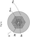
- Fig. 1a shows a cross-section of a delivery fiber 5 of a delivery fiber assembly.
- the delivery fiber 5 comprises a core region with a refractive index n core .
- the core is surrounded by a cladding region comprising a background material having a refractive index N bg and a plurality of microstructures in the form of inclusions 2a, 2b of solid material having refractive index up to N inc and extending in the length of the longitudinal axis of the delivery fiber, wherein N inc ⁇ N bg .
- the plurality of inclusions 2a, 2b in the cladding region is arranged in a cross-sectional pattern comprising at least 6 rings of inclusions surrounding the core region.
- the 3 in radial direction innermost rings of inclusions 2a have a lower refractive index than the 3 in radial direction outermost rings of inclusions 2b.
- the inclusions have substantially equal diameter. As explained above it may for some applications be advantageous to have different diameters for one ring of inclusions relative to another ring of inclusions.
- Fig. 1b shows a transmission loss spectrum of a fiber corresponding to the delivery fiber shown in fig. 1 with six rings of inclusions, but where all inclusions have same refractive index.
- the core has a diameter of 10 ⁇ m
- the inclusions have a refractive index which is 1.2% lower than the refractive index of the core and the cladding background silica material at 635 nm.
- the center to center distance between the inclusions in the cladding (also known as the pitch) is 6 ⁇ m and the diameter of the inclusions is 3 ⁇ m.
- the spectrum is obtained by sending light from a broad band spectrum light source through the fiber and performing a cut-back to separate the coupling loss.
- the peak at around 1400 nm is due to water absorption.
- the delivery fiber is single-mode in the entire transmission bandwidth of the delivery fiber. It can be seen that the delivery fiber has a very broad transmission bandwidth extending from about 425 nm to about 1500 nm.
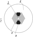
- the delivery fiber shown in Fig. 1c is an example of a PM fiber comprising a core region with a refractive index n core .
- the core is surrounded by a cladding region comprising a background material having a refractive index N bg and a plurality of microstructures in the form of inclusions 7a, 8b of solid material having refractive index up to N inc and extending in the length of the longitudinal axis of the delivery fiber, wherein N inc ⁇ N bg .
- the plurality of inclusions 7a, 7b in the cladding region is arranged in a cross-sectional pattern comprising at least 6 rings of inclusions surrounding the core region.
- a number of inclusions b with a higher refractive index than the other inclusions 7a is arranged in two opposite clusters for forming stress elements.
- the inclusions 7b with the higher refractive index are e.g. doped with boron.
- the diameter(d) of the inclusions in the cladding relative to the pitch ( ⁇ ) may have large influence on the guiding properties of the delivery fiber.
- the transmission loss is large if the d/ ⁇ is less than about 0.4.
- the fiber is multimode if d/ ⁇ is more than about 0.6.
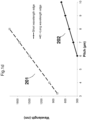
- the pitch ( ⁇ ) of the delivery fiber may have large influence on the spectral transmission bandwidth of the delivery fiber.
- the short wavelength transmission edge sets a upper limit to the pitch and where this limit increases with the required short wavelength edge, such that e.g. a short wavelength edge of 300 nm requires a pitch of less than 6 ⁇ m whereas a short wavelength edge of 600 nm requires a pitch of less than 9 ⁇ m.
- the long wavelength transmission edge sets a lower limit to the pitch and where this limit increases with the required long wavelength edge, such that e.g. a long wavelength edge of 800 nm requires a pitch of at least 3.2 ⁇ m whereas a long wavelength edge of 1500 nm requires a pitch of at least 6 ⁇ m.
- Fig. 1d shows the pitch shows an example of the long wavelength transmission edge (201) and short wavelength transmission edge (202) versus the pitch for a fiber according to the invention having a d/ ⁇ of about 0.5.
- the mode field diameter of the delivery fiber varies from about 8.0 ⁇ m at 500 nm to about 9.0 ⁇ m at 900 nm. In an embodiment the mode filed diameter of the fiber varies by less than about 20% from 500 nm to 900 nm.
- Fig. 2 shows a part of a delivery fiber assembly comprising the delivery fiber 5 and a connector member 6 mounted to the delivery fiber at a delivery end section of the delivery fiber comprising the delivery end 5a.
- the delivery fiber comprises a protection coating, such as a polymer protection coating.
- the connector member is advantageously an optical fiber connector of the type which in the prior art is commonly used to terminate the end of an optical standard fiber to enable easy connection and disconnection of two standard optical fibers with low loss.
- the optical fiber is typically aligned inside the optical connector member, so that the core region of the optical delivery fiber is centered inside a connector plane of the connector member.
- a polarizing or polarization maintaining fiber it is also possible to rotate the fiber so that the polarization axis is in a predetermined plane. Furthermore it is ensured that the end facet of the fiber is in the output plane of the connector member. This can e.g. be achieved by polishing the connector and fiber end facets.
- the position of the light being emitted from the output of the connector member is well known.
- the light will have its focal plane and thereby waist at the output plane of the connector.
- connectors have been introduced to the marked, such as e.g. FC, E-2000, SMA connectors, as well as connectors with built in beam expansion.
- fiber connector members having low loss and high power handling should advantageously be capable of handling average powers such as up to 100 mW or even up to several Watts.
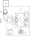
- the broad band source 10 shown in Fig. 3 comprises a broad band laser pulse generator 1 comprising a not shown optical pump source operable to generate pump pulses and a not shown microstructured optical fiber for generating broad band light pulses upon feeding of pump light where the optical pump source is arranged to launch pump pulses to the microstructured optical fiber.
- the broad band laser pulse generator 1 is in the form of a SuperK TM system marketed by NKT Photonics Denmark.
- the broad band source further comprises a delivery fiber 5 comprising solid inclusions as described above. The delivery fiber 5 is arranged for receiving at least a portion of at least some of said broad band light pulses.
- the broad band source 10 further comprises an optical component 3, preferably a filter 3 arranged between the broad band laser pulse generator 1 and the delivery fiber 5.
- the optical component 3 is for example a polarizer, a spectral filter (preferably tunable) and/or a beam splitter.
- the delivery fiber comprises a connector member 6 e.g. as described above.
- the connector member 6 is advantageously configured for delivering at least a part of said received portion of said broad band light pulses to an apparatus as described above.
- the broad band source 10 is coupled to an optical waveguide arranged for receiving light from the delivery fiber, here called the first delivery fiber.
- the optical waveguide arranged for receiving light from the first delivery fiber is in form of an additional delivery assembly comprising a second delivery optical fiber 22 and a second delivery fiber inlet end connector member 21 and a second delivery fiber output end termination unit 23.
- the connector member 6 of the delivery fiber assembly 5, 6 in the following referred to as the first delivery fiber assembly 5,6 is connected to the second delivery fiber inlet end connector member 21 using a mating sleeve 20.
- the connectors mechanically couple the core regions of the first and the second delivery fibers 5, 22 so that light can pass from the first delivery fiber 5 to the second delivery fiber 22 with low loss.
- the connector members are spring-loaded, so the fiber faces are pressed together when the connector members 6, 21 are mated. The resulting glass-to-glass or plastic-to-plastic contact eliminates signal losses that would be caused by an air gap between the joined fibers.
- the fiber termination unit 23 is advantageously a connector member, a collimator, a ball lens, grin lens or any other suitable termination unit.
- the second optical delivery fiber 22 can in principle be any kind of optical fiber, preferably having a relative broad transmission bandwidth e.g. at least about 200 nm or more, and preferably the transmission bandwidth of the second optical delivery fiber 22 at least partially overlaps the transmission bandwidth of the first delivery fiber 5.
- the second optical delivery fiber 22 is substantially identical to the first delivery fiber 5.
- the broad band source 10 comprising the broad band laser pulse generator 1 and the first fiber delivery assembly 5,6 can be replaced without replacing the second fiber delivery assembly 21, 22, 23 or vice versa.
- the broad band source 10 and said second fiber delivery assembly 21, 22, 23 is built into an apparatus or alternatively the second fiber delivery assembly 21, 22, 23 is built into an apparatus while the broad band source 10 is arranged to feed light to the apparatus via the connection between the connector members 6, 21.
- apparatus examples include microscopes, bio- imaging systems (such as e.g. OCT, SLO, STED, CARS and photoacoustic systems), alignment or overlay system and manufacturing equipment (such as e.g. semiconductor manufacturing equipment).
- This embodiment of the invention enables that the broad band source 10 easily can be disconnected for service and/or can be replaced independently of said second fiber assembly 21, 22, 23, which e.g. may be more difficult to disconnect from the remainder of the apparatus.
- the supercontinuum source and first fiber delivery assemble constituting a broad band source of an embodiment of the invention can be comprised in a first module, whereas the second fiber assembly 21, 22, 23 is part of a second module such as e.g. an alignment sensor in a semiconductor wafer scribing system.
- the invention enables a modular build-up of the semiconductor wafer scribing system. If the semiconductor wafer scribing system breaks down, then the error can be located to the specific module which has failed, and this can be replaced independently of the other modules. This improves risk management for the semiconductor wafer scribing system compared to having to replace both modules at the same time.
- the second fiber delivery assembly 21, 22, 23 is used in bio-medical imaging or surgical applications.
- examples of such embodiments include endoscopy, colonoscopy, rhinoscopy and bronoscopy as well as other applications where a part of the second optical fiber enters inside either a human or animal body.
- the broad band source 10 as shown in Fig. 3 can easily be connected to the connection member 21 as described above.
- the second fiber delivery assembly is sterilized before use. In an embodiment the second fiber delivery assembly is disposable.
- Fig. 5 is a schematic illustration of another broad band source.
- the broad band system 10 may be as described above and the second optical delivery fiber assembly 21, 22, 23 may be as described in Fig. 4 .
- the fiber termination unit 23 advantageously is or comprises a collimator for focusing light towards a sample 30.
- the second fiber delivery assembly 21, 22, 23 is built into an apparatus and the broad band source 10 is optionally arranged as a built in module in the apparatus and is arranged to feed light to the apparatus via the connection between the connector members 6, 21.
- the source 10 comprises or is optically connected to an optical detector 34, and the optical component 3 comprises an additional filter 32 arranged to direct a portion of light 33 reflected by the sample and guided by the fibers 5 and 22.
- the additional filter is advantageously a splitter.
- the delivery fiber 5 and the second optical fiber 22 are double clad fibers. Thereby a portion of the light 31 reflected by the sample can be guided to the optical detector via the second optical delivery fiber assembly 21, 22, 23 and the first delivery fiber assembly 5, 6.
- the delivery fiber 5 and the second optical fiber 22 comprise a cladding with an NA of at least 0.1, such as at least 0.15, such as at least 0.22. Also in this embodiment the fibers 5, 22 will guide some of the light 31 which is being reflected from the sample under test.
- the optical component 3 comprises means to separate the light that is reflected from the sample and guided by the fibers 33 from at least some of the light from the broad band source.
- Such means is for example a beam splitter 32.
- a double-clad fiber coupler is applied instead of a splitter for example by providing a double-clad fiber coupler at the input end of the first delivery fiber.
- the double-clad fiber coupler is advantageously configured for separating core and cladding light ,e.g. by having a 2X2 port structure comprising multimode double clad fibers on two ports of the coupler and single mode double clad fibers on the other two ports, such as e.g. the DC1300 LEB offered by Thorlabs.
- a portion or all of the reflected light could be separated from the major part of the light from the broad band source but any other means known to the skilled person.
- the reflected and separated light is transmitted to an optical detector 34, such as e.g. a photodiode or a spectrometer.
- an optical detector 34 such as e.g. a photodiode or a spectrometer.
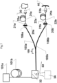
- the interferometer comprises a broad band source comprising an optical pump source 101a operable to generate pump pulses an air hole microstructured optical fiber 101b for generating broad band light pulses upon feeding of pump pulses from said optical pump source 101a and the first delivery fiber assembly 105a, 106a comprising a delivery fiber 105a comprising solid inclusions as described above and a connector member 106a also as described above.
- the first delivery fiber assembly 105a, 106a is connected to the microstructured optical fiber via a delivery fiber connector member 106c which is advantageously as the connector member described above, and an end cap connection member 101c.
- the air holes along less than a few mm of the air hole microstructured optical fiber 101b are collapsed and the light beam is collimated by a not shown lens.
- the delivery fiber connector member 106c and the end cap connection member 101c are mated and held together by a mating sleeve 20c.
- the air hole microstructured optical fiber 101b is spliced to the delivery fiber 105 by splicing and/or by using a using a GRIN lens as described above.
- the interferometer comprises a second fiber assembly 21a, 22a, 23a which advantageously is as the second fiber assembly 21, 22, 23 described above, and the connector members 106a, 21a are connected and hold together by mating sleeve 20a.
- the fused coupler delivery fiber assembly 105b, 106b is connected to a third fiber assembly 21b, 22b, 23b which advantageously is as the second fiber assembly 21, 22, 23 described above, and the connector members 106b, 21b are connected and held together by mating sleeve 20b.
- the interferometer further comprises a mirror 40 or another reference unit arranged to reflect light emitted via the fiber termination unit 23b. In an alternative embodiment the reference unit is not included in the apparatus but can be selected by the user.
- the fused coupler delivery fiber assembly 105b is further connected to a detector 124, such as a spectrometer.
- the broad band source may comprise one or more tunable or non-tunable filters and or a pulse picker and one or more amplifiers such as it is well known in the art.
- a coupler has a bar port, where the light goes straight through from one top arm to the other top arm (or from the bottom arm to the other bottom arm), and a cross port where the light goes from the top arm to bottom arm, or vice versa.
- couplers are close to have a very low loss such that all the light is send to the bar port or the cross port.
- the two top arms are provided by the delivery fiber 105a on either side of the component section 100 and the bottom arms are provided by the delivery fiber 105b on either side of the component section.
- the bar ports and the cross port are provided by the component section 100.
- the bar port has a transmission coefficient of x and the cross arm a transmission coefficient of (1-x). The transmission coefficient is the same irrespective of which direction the coupler is traversed.
- the fused component section 100 some of the light (x) is transmitted further via the delivery fiber 105a and some of the light (1-x) is transmitted further via the fused coupler delivery fiber 105b.
- the light portion (X) transmitted from the fused component section 100 and via the delivery fiber 105a is transmitted to the second fiber assembly 21a, 22a, 23a and via the fiber termination unit 23a the light pulses are emitted towards a sample 30 and reflected light 31a is transmitted in the opposite direction via the second fiber 22a and the delivery fiber 105a until the remitted light reaches the fused component section 100. From there a portion of remitted light is transmitted further via the fused coupler delivery fiber 105b to the detector 104.
- the light portion (1-X) transmitted from the fused component section 100 and via the fused coupler delivery fiber 105b is transmitted to the third fiber assembly 21b, 22b, 23b and via the fiber termination unit 23b the light pulses are emitted towards a mirror 40 and reflected light 31b is transmitted in the opposite direction via the third fiber 22b and the fused coupler delivery fiber 105b until the remitted light reaches the fused component section 100. From there a portion of remitted light is transmitted further via the fused coupler delivery fiber 105b to the detector 104.
- the mirror reflects substantially all of the light that is incident on it.
- the interferometer thereby has two interferometer arms, one that is guiding light to a sample and re-transmit reflected light and one that is guiding light to a reference unit (e.g. a mirror) and re-transmits reflected light.
- one interferometer arm is configured for being focused onto a tissue sample and for scanning the sample in an X-Y longitudinal raster pattern. The other interferometer arm is bounced off the reference mirror. Reflected light from the tissue sample is combined with reflected light from the reference.
- the light goes from the broad band laser goes through the cross port of the coupler to reach the mirror 40. It is reflected from the mirror and goes back through the bar port of the coupler to reach the detector 124. Assuming that the reflection is loss less the transmission coefficient for the entire path is the product of the two transmission coefficients, i.e. x(1-x).
- Fig. 7 is a schematic illustration of a delivery fiber comprising a combiner.
- the delivery fibers 105a, 105b, 22a, 22b are all solid fibers comprising microstructures in form of inclusions as described above and preferably all of the delivery fibers 105a, 105b, 22a, 22b have a transmission bandwidth of 200 nm or more, preferably the transmission bandwidths are overlapping or identical.
- Fig. 7 is a schematic illustration of an apparatus in form of another type of interferometer e.g. for use in optical metrology e.g. for thin film, wafer, optical critical dimension (OCD), overlay and wafer stress for transistor and interconnect metrology applications.
- optical metrology e.g. for thin film, wafer, optical critical dimension (OCD), overlay and wafer stress for transistor and interconnect metrology applications.
- OCD optical critical dimension
- the interferometer comprises a first delivery fiber assembly 105a, 106a comprising a fused splitter delivery fiber assembly 105b, 106b where the first delivery fiber assembly 105a, 106a and the fused splitter delivery fiber assembly 106b is fused in a component section 100.
- the interferometer comprises a broad band source comprising an optical pump source 101a operable to generate pump pulse, a microstructured optical fiber 101b for generating broad band light pulses upon feeding of pump pulses from said optical pump source 101a and the first delivery fiber assembly 105a, 106a comprising a delivery fiber 105a comprising solid inclusions as described above and a connector member 106a also as described above.
- the first delivery fiber assembly 105a, 106a is connected to the microstructured optical fiber via a filter 32 arranged to directing a portion of reflected light 33 reflected by the sample 30e and the reference unit 40 towards an optical detector 34.
- the remaining parts are as in the example of Fig. 7 .
- Fig. 8 illustrates a spectral engine source suitably for supplying light to an apparatus.
- the spectral engine source comprises three lasers 121, 222, 123 emitting laser beams 121a, 122a, 123a respectively.
- the laser beams 121a, 122a, 123a differs from each other with at least one wavelength as described above.
- the lasers 121, 222, 123 may be of same or of different types, such as one or more gas lasers, one or more chemical lasers, one or more metal-vapor lasers and/or one or more semiconductor lasers.
- the spectral engine source further comprises a multiplexer M here illustrated by a number of mirrors arranged to combine the beams 121a, 122a, 123a into one single multiplexed beam M.
- the multiplexer may be any kind of multiplexer or combiner capable of combining least a portion of the laser beams of each of the lasers and for collimating the received light to a multiplexed beam.
- the multiplexer M collimates the 121a, 122a, 123a sufficiently close to be received by the delivery fiber of the spectral engine source of the invention.
- the delivery fiber is not shown of the spectral engine source, however the delivery fiber is arranged to collect the multiplexed beam M and to delivering at least a part of the received multiplexed beam M to the apparatus,
- Fig. 9 illustrates another spectral engine source suitably for supplying light to an apparatus.
- the spectral engine source comprises 5 lasers 131, 232, 133, 134, 135 emitting laser beams 131a, 132a, 133a, 134a, 135a respectively.
- the laser beams 131a, 132a, 133a, 134a, 135a differs from each other with at least one wavelength.
- laser beam 131a may comprise wavelength (s) in the range of 400-500nm
- laser beam 132a may comprise wavelength (s) in the range of 500-600nm
- laser beam 133a may comprise wavelength (s) in the range of 600-700nm
- laser beam 135a may comprise wavelength (s) in the range of 800-900nm.
- the spectral engine source further comprises a multiplexer M here illustrated by a number of mirrors arranged to combine the beams 131a, 132a, 133a, 134a, 135a into one single multiplexed beam M.
- the spectral engine source also comprises a not shown delivery fiber as described above for receiving the multiplexed beam and to delivering at least a part of the received multiplexed beam M to an apparatus,
- Fig. 10 illustrates an apparatus comprising a light source LS selected from a broad band source, a broad band source system or a spectral engine source with a delivery fiber DL as described above.
- the apparatus is a lithographic apparatus and comprises an illumination system (illuminator) IL arranged to receive the light from the delivery fiber of the light source LS.
- the illuminator IL may comprise an adjuster AD for adjusting the angular intensity distribution of the radiation beam received from the light source LS.
- the illuminator IL may comprise various other components, such as an integrator IN and a condenser CO.
- the illuminator may be used to condition the radiation bean, to have a desired uniformity and intensity distribution in its cross-section.
- the radiation beam B is incident on a patterning device (e.g., mask MA), which is held on the support structure (e.g., mask table MT), and is patterned by the patterning device. Having traversed the mask MA, the radiation beam B passes through the projection system PS, which focuses the beam onto a target portion C of the substrate W.
- the substrate table WT can be moved accurately, e.g. so as to position different target portions C in the path of the radiation beam B.
- the first positioner PM and another position sensor (which is not explicitly depicted in Fig.
- the mask table MT can be used to accurately position the mask MA with respect to the path of the radiation beam B, e.g. after mechanical retrieval from a mask library, or during a scan.
- movement of the mask table MT may be realized with the aid of a long-stroke module (coarse positioning) and a short-stroke module (fine positioning), which form part of the first positioner PM.
- movement of the substrate table WT may be realized using a long-stroke module and a short-stroke module, which form part of the second positioner PW.
- the mask table MT may be connected to a short-stroke actuator only, or may be fixed.
- Mask MA and substrate W may be aligned using mask alignment marks M1, M2 and substrate alignment marks P1, P2.
- the substrate alignment marks as illustrated occupy dedicated target portions, they may be located in spaces between target portions (these are known as scribe-lane alignment marks).
- the mask alignment marks may be located between the dies.
- the apparatus may for example operate as described in US2007013921
- Fig. 11 illustrates an apparatus comprising scanning microscope that is embodied as a confocal scanning microscope and a light source LS selected from a broad band source, a broad band source system or a spectral engine source with a delivery fiber DL as described above.
- the light source LS delivers an illuminating light beam 211 via the delivery fiber DL
- the scanning microscope comprises an acoustooptical component 213 that is embodied as AOTF 215.
- Detected light beam 229 coming from the specimen travels in the opposite direction through scanning optical system 221, tube optical system 223, and objective 225, and arrives via scanning mirror 219 at acoustooptical component 213 which conveys detected light beam 229 to detector 231, which is embodied as a multi-band detector.
- Illuminating light beam 211 is depicted as a solid line in the drawing, and detected light beam 229 as a dashed line.
- Illumination pinhole 233 and detection pinhole 235 that are usually provided in a confocal scanning microscope are schematically drawn in for the sake of completeness. Omitted in the interest of better clarity, however, are certain optical elements for guiding and shaping the light beam.
- Acoustooptical component 213, which serves to select the wavelength spectrum that is chosen, is configured as AOTF 215, through which an acoustic wave passes. The acoustic wave is generated by an electrically activated piezo acoustic generator 237.
- Activation is accomplished by a high-frequency source 239 that generates an electromagnetic high-frequency wave that exhibits an adjustable HF spectrum.
- the HF spectrum is chosen in such a way that only those portions of illuminating light beam 211 having the desired wavelength arrive at beam deflection device 217.
- the other portions of illuminating light beam 211 not influenced by the acoustic excitation are directed into a beam trap 241.
- the power level of the illuminating light beam 211 can be selected by varying the amplitude of the acoustic wave.
- the crystal sectioning and orientation of acoustooptical component 213 are selected in such a way that with a single coupling-in direction, different wavelengths are deflected in the same direction.
- a computer 243 is used to choose a second or third wavelength spectrum.
- Monitor 247 of computer2 43 serves as the display for the spectral composition. Selection of the wavelength spectrum together with its spectral composition is accomplished on the basis of a graph G within a coordinate system having two coordinate axes X, Y. The wavelength of the light is plotted on coordinate axis X, and its power level on coordinate axis Y.
- Computer 243 controls high-frequency source 239 in accordance with the user's stipulation. The user makes adjustments using computer mouse 257. Depicted on monitor 247 is a slider 259 that serves for adjustment of the overall light power level of illuminating light beam 11 or detected light beam 229.
Claims (11)
- Ensemble fibres de distribution adapté pour distribuer une lumière à large bande et comprenant une fibre de distribution (5) et un élément connecteur, ladite fibre de distribution ayant une extrémité d'entrée pour lancer de la lumière et une extrémité de distribution pour distribuer de la lumière, ladite fibre de distribution comprenant une région centrale et un région de gaine entourant la région centrale, dans lequel la région de gaine comprend un matériau de fond de gaine ayant un indice de réfraction Nbg et une pluralité de microstructures sous la forme d'inclusions s'étendant longitudinalement (2a, 2b, 7a, 7b) de matériau solide ayant un indice de réfraction allant jusqu'à Ninc, dans lequel Ninc < Nbg, dans lequel la pluralité d'inclusions est agencée selon un motif en coupe comprenant au moins deux anneaux d'inclusions entourant la région centrale, ladite région centrale ayant un diamètre allant jusqu'à 15 um, ledit élément connecteur étant monté sur ladite fibre de distribution au niveau d'une section d'extrémité de distribution de la fibre de distribution, ladite fibre de distribution ayant une largeur de bande de transmission de 200 nm ou plus, dans lequel la fibre de distribution a une perte de transmission inférieure à 0,5 dB/m à des longueurs d'onde dans la largeur de bande de transmission, et dans lequel ladite la fibre de distribution est une fibre optique à maintien de polarisation.
- Ensemble fibres de distribution selon la revendication 1, dans lequel ledit élément connecteur est monté sur ladite fibre de distribution microstructurée au niveau de ladite section d'extrémité de distribution de la fibre de distribution microstructurée à une distance de ladite extrémité de distribution, de sorte que l'extrémité de distribution passe à travers l'élément connecteur pour connecter ladite extrémité de distribution en contact physique avec un guide d'onde récepteur.
- Ensemble fibres de distribution selon la revendication 1 ou la revendication 2, dans lequel pour au moins une longueur d'onde dans ladite largeur de bande de transmission et au moins le long de ladite section d'extrémité de distribution, la fibre de distribution microstructurée a un diamètre de champ de mode constant.
- Ensemble fibres de distribution selon l'une quelconque des revendications précédentes, dans lequel la fibre de distribution microstructurée au moins le long de ladite section d'extrémité de distribution a une plage de diamètre de champ de mode pour ladite longueur d'onde de transmission, dans lequel la plage de diamètre de champ de mode est de 30 % ou moins du diamètre de champ de mode le plus bas de la plage.
- Ensemble fibres de distribution selon l'une quelconque des revendications précédentes, dans lequel ladite fibre de distribution est monomode pour au moins une longueur d'onde dans ladite largeur de bande de transmission.
- Ensemble fibres de distribution selon l'une quelconque des revendications précédentes, dans lequel ladite fibre de distribution comprend un ou plusieurs éléments de contrainte.
- Ensemble fibres de distribution selon l'une quelconque des revendications précédentes, dans lequel la fibre de distribution a un diamètre de région centrale au pas d/∧ qui est de 0,7 ou moins.
- Ensemble fibres de distribution selon l'une quelconque des revendications précédentes, dans lequel la pluralité d'inclusions dans la région de gaine est agencée selon un motif en coupe comprenant au moins quatre anneaux d'inclusions entourant la région centrale.
- Ensemble fibres de distribution selon l'une quelconque des revendications précédentes, dans lequel la fibre de distribution est une fibre de silice et les inclusions solides comprennent de la silice sous-dopée.
- Ensemble fibres de distribution selon l'une quelconque des revendications précédentes, dans lequel la fibre de distribution est une fibre entièrement solide, de préférence la fibre de distribution est une fibre entièrement en silice, dans lequel la région centrale, la région de gaine et/ou les inclusions sont dopées pour atteindre leurs indices de réfraction respectifs.
- Ensemble fibres de distribution selon l'une quelconque des revendications précédentes, dans lequel l'ensemble comprend en outre un élément connecteur d'extrémité d'entrée, l'élément connecteur d'extrémité d'entrée étant monté sur ladite fibre de distribution microstructurée au niveau d'une section d'extrémité d'entrée de la fibre de distribution comprenant ladite extrémité d'entrée, ledit élément connecteur d'extrémité d'entrée étant configuré pour connecter ladite extrémité d'entrée en contact physique avec une unité de lancement de lumière.
Applications Claiming Priority (2)
| Application Number | Priority Date | Filing Date | Title |
|---|---|---|---|
| DKPA201570393 | 2015-06-25 | ||
| PCT/DK2016/050221 WO2016206700A1 (fr) | 2015-06-25 | 2016-06-24 | Ensemble fibres de distribution et source à large bande |
Publications (4)
| Publication Number | Publication Date |
|---|---|
| EP3314318A1 EP3314318A1 (fr) | 2018-05-02 |
| EP3314318A4 EP3314318A4 (fr) | 2019-02-20 |
| EP3314318B1 true EP3314318B1 (fr) | 2023-08-09 |
| EP3314318C0 EP3314318C0 (fr) | 2023-08-09 |
Family
ID=57584717
Family Applications (1)
| Application Number | Title | Priority Date | Filing Date |
|---|---|---|---|
| EP16813773.5A Active EP3314318B1 (fr) | 2015-06-25 | 2016-06-24 | Ensemble fibres de distribution |
Country Status (7)
| Country | Link |
|---|---|
| US (4) | US10649136B2 (fr) |
| EP (1) | EP3314318B1 (fr) |
| JP (2) | JP6835752B2 (fr) |
| KR (1) | KR20180019739A (fr) |
| CN (3) | CN107710040A (fr) |
| HK (1) | HK1250793A1 (fr) |
| WO (1) | WO2016206700A1 (fr) |
Families Citing this family (15)
| Publication number | Priority date | Publication date | Assignee | Title |
|---|---|---|---|---|
| CN107710040A (zh) | 2015-06-25 | 2018-02-16 | Nkt光子学有限公司 | 传输光纤组件和宽带光源 |
| US11300683B2 (en) | 2016-12-30 | 2022-04-12 | Innovusion Ireland Limited | Multiwavelength LiDAR design |
| WO2018202269A1 (fr) | 2017-05-04 | 2018-11-08 | Nkt Photonics A/S | Ensemble source de lumière |
| US11221211B2 (en) | 2018-01-26 | 2022-01-11 | Vanderbilt University | Systems and methods for non-destructive evaluation of optical material properties and surfaces |
| US11927696B2 (en) | 2018-02-21 | 2024-03-12 | Innovusion, Inc. | LiDAR systems with fiber optic coupling |
| US20190265339A1 (en) * | 2018-02-23 | 2019-08-29 | Innovusion Ireland Limited | Distributed lidar systems |
| CN108802989B (zh) * | 2018-08-17 | 2020-06-02 | 华中科技大学 | 一种并行多区域成像装置 |
| KR102135593B1 (ko) * | 2018-11-29 | 2020-07-20 | 재단법인대구경북과학기술원 | 다중모드 현미경 |
| US11493751B2 (en) | 2019-01-23 | 2022-11-08 | Vanderbilt University | Systems and methods for compact optical relay |
| CN110289471B (zh) * | 2019-05-31 | 2020-11-03 | 江苏大学 | 一种太赫兹波导 |
| EP3889662A1 (fr) * | 2020-04-03 | 2021-10-06 | Leica Microsystems CMS GmbH | Système d'éclairage optique pour un microscope et microscope |
| CN111812770A (zh) * | 2020-06-15 | 2020-10-23 | 艾菲博(宁波)光电科技有限责任公司 | 一种实芯保偏无截止单模微结构光纤及其制备工艺 |
| EP4258052A1 (fr) | 2022-04-08 | 2023-10-11 | NKT Photonics A/S | Système de supercontinuum avec détection spectrale |
| EP4258051A1 (fr) | 2022-04-08 | 2023-10-11 | NKT Photonics A/S | Système supercontinuum réglable |
| CN115248475A (zh) * | 2022-08-04 | 2022-10-28 | 艾菲博(宁波)光电科技有限责任公司 | 一种微结构保偏光纤 |
Citations (3)
| Publication number | Priority date | Publication date | Assignee | Title |
|---|---|---|---|---|
| US20050084223A1 (en) * | 2002-01-29 | 2005-04-21 | Masatoshi Tanaka | Polarization retaining photonic crystal fiber |
| US20060096325A1 (en) * | 2003-02-12 | 2006-05-11 | Takaharu Kinoshita | Method for manufacturing photonic crystal fiber |
| US7289709B2 (en) * | 2003-12-19 | 2007-10-30 | Crystal Fibre A/S | Photonic crystal fibres comprising stress elements |
Family Cites Families (31)
| Publication number | Priority date | Publication date | Assignee | Title |
|---|---|---|---|---|
| DE60025766T2 (de) * | 1999-02-19 | 2006-10-12 | Crystal Fibre A/S | Herstellungsverfahren einer photonischen Kristallfaser |
| AU2003254639A1 (en) * | 2002-08-20 | 2004-03-11 | Crystal Fibre A/S | Photonic crystal fibre |
| US6901197B2 (en) * | 2003-01-13 | 2005-05-31 | Sumitomo Electric Industries, Ltd. | Microstructured optical fiber |
| US7126693B2 (en) * | 2004-03-29 | 2006-10-24 | Carl Zeiss Meditec, Inc. | Simple high efficiency optical coherence domain reflectometer design |
| EP1846784B1 (fr) * | 2004-12-30 | 2016-07-20 | Imra America, Inc. | Fibres a largeurs de bande photoniques |
| JP4869734B2 (ja) | 2005-04-25 | 2012-02-08 | オリンパス株式会社 | 多光子励起走査型レーザ顕微鏡 |
| US20070002336A1 (en) | 2005-06-30 | 2007-01-04 | Asml Netherlands B.V. | Metrology apparatus, lithographic apparatus, process apparatus, metrology method and device manufacturing method |
| JP5390741B2 (ja) | 2005-10-11 | 2014-01-15 | 古河電気工業株式会社 | 光ファイバおよび光伝送媒体 |
| EP1969685A2 (fr) * | 2005-11-18 | 2008-09-17 | Crystal Fibre A/S | Fibres optiques actives ameliorees possedant un mecanisme de filtrage a selection de longueur d'onde, leur procede de fabrication et d'utilisation |
| US7356233B2 (en) * | 2006-04-13 | 2008-04-08 | Furakawa Electric North America Inc. | Suppression of transverse modes in bandgap microstructure optical fibers |
| WO2009042347A1 (fr) | 2007-09-26 | 2009-04-02 | Imra America, Inc. | Fibres optiques en verre à âme de grande dimension |
| GB0719376D0 (en) | 2007-10-03 | 2007-11-14 | Univ Bath | Hollow-core photonic crystal fibre |
| US9048627B2 (en) * | 2007-12-18 | 2015-06-02 | Nkt Photonics A/S | Mode-locked fiber laser with improved life-time of saturable absorber |
| GB0800936D0 (en) | 2008-01-19 | 2008-02-27 | Fianium Ltd | A source of optical supercontinuum generation having a selectable pulse repetition frequency |
| US8406594B2 (en) * | 2008-08-18 | 2013-03-26 | Nkt Photonics A/S | Optical fiber with resonant structure of cladding features connected to light sink |
| US8731009B2 (en) | 2009-04-08 | 2014-05-20 | Nkt Photonics A/S | Broadband high power light source |
| CN102687048B (zh) | 2009-08-14 | 2015-04-01 | Nkt光子学有限公司 | 涉及光子晶体光纤的熔接与连接的改进 |
| WO2011023201A1 (fr) | 2009-08-28 | 2011-03-03 | Nkt Photonics A/S | Laser à fibres pulsé |
| JP5605630B2 (ja) * | 2009-10-23 | 2014-10-15 | 日本電信電話株式会社 | 光ファイバ |
| JP2011257589A (ja) * | 2010-06-09 | 2011-12-22 | Olympus Corp | レーザ顕微鏡、レーザ顕微鏡システムおよびレーザ光伝達手段 |
| ES2932623T3 (es) * | 2010-08-30 | 2023-01-23 | Nkt Photonics As | Fibra óptica ahusada para la generación de supercontinuo |
| JP5557290B2 (ja) | 2011-02-15 | 2014-07-23 | 日本電信電話株式会社 | 光ファイバ |
| US8849083B1 (en) | 2011-04-28 | 2014-09-30 | Nufern | All glass leakage channel fibers and devices using them |
| EP2533081A1 (fr) | 2011-06-09 | 2012-12-12 | Universite De Lille 1 Sciences Et Technologies | Fibre de cristal photonique hybride |
| CA2874787C (fr) | 2012-06-01 | 2023-04-04 | Nkt Photonics A/S | Source de lumiere supercontinuum, et systeme et procede de mesure |
| JP2014132287A (ja) | 2013-01-04 | 2014-07-17 | Fujikura Ltd | フォトニックバンドギャップファイバ |
| DK3019899T3 (da) | 2013-07-10 | 2021-10-11 | Nkt Photonics As | Superkontinuumdannelse i mikrostrukturerede optiske fibre ved tilspidsning og tilpasning af ikke-dispergerende bølgelængde(r) |
| US9841557B2 (en) | 2013-07-10 | 2017-12-12 | Nkt Photonics A/S | Microstructured optical fiber, supercontinuum light source comprising microstructured optical fiber and use of such light source |
| WO2015077021A1 (fr) | 2013-11-22 | 2015-05-28 | Imra America, Inc | Fibres de polarisation et d'entretien de polarisation à canal de fuite |
| PL227732B1 (pl) | 2013-12-04 | 2018-01-31 | Polskie Centrum Fotoniki I Swiatlowodów | Mikrostrukturalny światłowód z selektywnie powiększonymi przestrzeniami o zmniejszonym współczynniku załamania światła zwłaszcza do generacji efektów nieliniowych i pomiaru naprężeń |
| CN107710040A (zh) | 2015-06-25 | 2018-02-16 | Nkt光子学有限公司 | 传输光纤组件和宽带光源 |
-
2016
- 2016-06-24 CN CN201680037135.2A patent/CN107710040A/zh active Pending
- 2016-06-24 EP EP16813773.5A patent/EP3314318B1/fr active Active
- 2016-06-24 WO PCT/DK2016/050221 patent/WO2016206700A1/fr unknown
- 2016-06-24 KR KR1020187002255A patent/KR20180019739A/ko not_active Application Discontinuation
- 2016-06-24 US US15/738,623 patent/US10649136B2/en active Active
- 2016-06-24 CN CN202010170503.9A patent/CN111239889A/zh active Pending
- 2016-06-24 CN CN202210966063.7A patent/CN115166959A/zh active Pending
- 2016-06-24 JP JP2017566732A patent/JP6835752B2/ja active Active
-
2018
- 2018-08-09 HK HK18110216.7A patent/HK1250793A1/zh unknown
-
2020
- 2020-05-11 US US16/871,297 patent/US11137541B2/en active Active
- 2020-12-07 JP JP2020202480A patent/JP7036891B2/ja active Active
-
2021
- 2021-08-19 US US17/406,646 patent/US11703635B2/en active Active
-
2023
- 2023-05-31 US US18/326,562 patent/US20230384512A1/en active Pending
Patent Citations (3)
| Publication number | Priority date | Publication date | Assignee | Title |
|---|---|---|---|---|
| US20050084223A1 (en) * | 2002-01-29 | 2005-04-21 | Masatoshi Tanaka | Polarization retaining photonic crystal fiber |
| US20060096325A1 (en) * | 2003-02-12 | 2006-05-11 | Takaharu Kinoshita | Method for manufacturing photonic crystal fiber |
| US7289709B2 (en) * | 2003-12-19 | 2007-10-30 | Crystal Fibre A/S | Photonic crystal fibres comprising stress elements |
Non-Patent Citations (1)
| Title |
|---|
| LYNGSO J. K. ET AL: "Polarization maintaining hybrid TIR / bandgap all-solid photonic crystal fiber", LASERS AND ELECTRO-OPTICS, 2008. CLEO 2008. CONFERENCE ON, 1 May 2008 (2008-05-01), Piscataway, NJ, USA, pages 1 - 2, XP055811873, ISBN: 978-1-55752-859-9, DOI: 10.1109/CLEO.2008.4551537 * |
Also Published As
| Publication number | Publication date |
|---|---|
| JP2021047446A (ja) | 2021-03-25 |
| EP3314318A4 (fr) | 2019-02-20 |
| JP7036891B2 (ja) | 2022-03-15 |
| US11137541B2 (en) | 2021-10-05 |
| JP6835752B2 (ja) | 2021-02-24 |
| EP3314318A1 (fr) | 2018-05-02 |
| CN115166959A (zh) | 2022-10-11 |
| KR20180019739A (ko) | 2018-02-26 |
| WO2016206700A1 (fr) | 2016-12-29 |
| US11703635B2 (en) | 2023-07-18 |
| CN107710040A (zh) | 2018-02-16 |
| US10649136B2 (en) | 2020-05-12 |
| CN111239889A (zh) | 2020-06-05 |
| HK1250793A1 (zh) | 2019-01-11 |
| JP2018527601A (ja) | 2018-09-20 |
| US20180188447A1 (en) | 2018-07-05 |
| EP3314318C0 (fr) | 2023-08-09 |
| US20200341190A1 (en) | 2020-10-29 |
| US20230384512A1 (en) | 2023-11-30 |
| US20210382230A1 (en) | 2021-12-09 |
Similar Documents
| Publication | Publication Date | Title |
|---|---|---|
| US11703635B2 (en) | Delivery fiber assembly and a broad band source | |
| US10827911B2 (en) | Optical imaging system employing vortex fiber for multiple-mode illumination | |
| US7953308B2 (en) | System and method for fiber optic bundle-based illumination for imaging system | |
| US8861910B2 (en) | Fused fiber optic coupler arrangement and method for use thereof | |
| JP5745851B2 (ja) | モジュール式撮像デバイス、前記デバイス用のモジュール、及び前記撮像デバイスの作動方法 | |
| US20080192339A1 (en) | Laser Microscope | |
| WO2018001442A1 (fr) | Résonateur optique, procédé de fabrication du résonateur optique et ses applications | |
| KR101278285B1 (ko) | 렌즈 일체형 광섬유쌍 프로브를 이용한 이미징 시스템 | |
| US20120229879A1 (en) | Mirror cascade for bundling a plurality of light sources and a laser-scanning microscope | |
| JP2008170471A (ja) | ファイバレンズ、ファイバレンズアレイ、ファイバコリメータおよび光モジュール | |
| WO2008053190A1 (fr) | Microscope homofocal | |
| CN117555081B (zh) | 一种多光子显微镜及多光子显微成像系统 | |
| CN101634730A (zh) | 光转化系统及方法 | |
| GB2580607A (en) | Dual fibre optical apparatus | |
| GB2601409A (en) | Dual fibre optical apparatus | |
| CN113454508A (zh) | 双非对称光纤耦合器 | |
| Pelaprat et al. | OPTICAL COHERENCE TOMOGRAPHY: Monolithic fiberoptic probes enable medical imaging with OCT |
Legal Events
| Date | Code | Title | Description |
|---|---|---|---|
| STAA | Information on the status of an ep patent application or granted ep patent |
Free format text: STATUS: THE INTERNATIONAL PUBLICATION HAS BEEN MADE |
|
| PUAI | Public reference made under article 153(3) epc to a published international application that has entered the european phase |
Free format text: ORIGINAL CODE: 0009012 |
|
| STAA | Information on the status of an ep patent application or granted ep patent |
Free format text: STATUS: REQUEST FOR EXAMINATION WAS MADE |
|
| 17P | Request for examination filed |
Effective date: 20180122 |
|
| AK | Designated contracting states |
Kind code of ref document: A1 Designated state(s): AL AT BE BG CH CY CZ DE DK EE ES FI FR GB GR HR HU IE IS IT LI LT LU LV MC MK MT NL NO PL PT RO RS SE SI SK SM TR |
|
| AX | Request for extension of the european patent |
Extension state: BA ME |
|
| DAV | Request for validation of the european patent (deleted) | ||
| DAX | Request for extension of the european patent (deleted) | ||
| REG | Reference to a national code |
Ref country code: DE Ref legal event code: R079 Ref document number: 602016081812 Country of ref document: DE Free format text: PREVIOUS MAIN CLASS: G02B0006032000 Ipc: G02B0006020000 Ref country code: DE Ref legal event code: R079 Free format text: PREVIOUS MAIN CLASS: G02B0006032000 Ipc: G02B0006020000 |
|
| A4 | Supplementary search report drawn up and despatched |
Effective date: 20190117 |
|
| RIC1 | Information provided on ipc code assigned before grant |
Ipc: G02B 6/02 20060101AFI20190111BHEP |
|
| STAA | Information on the status of an ep patent application or granted ep patent |
Free format text: STATUS: EXAMINATION IS IN PROGRESS |
|
| 17Q | First examination report despatched |
Effective date: 20210615 |
|
| STAA | Information on the status of an ep patent application or granted ep patent |
Free format text: STATUS: EXAMINATION IS IN PROGRESS |
|
| GRAP | Despatch of communication of intention to grant a patent |
Free format text: ORIGINAL CODE: EPIDOSNIGR1 |
|
| STAA | Information on the status of an ep patent application or granted ep patent |
Free format text: STATUS: GRANT OF PATENT IS INTENDED |
|
| INTG | Intention to grant announced |
Effective date: 20230418 |
|
| GRAS | Grant fee paid |
Free format text: ORIGINAL CODE: EPIDOSNIGR3 |
|
| GRAA | (expected) grant |
Free format text: ORIGINAL CODE: 0009210 |
|
| STAA | Information on the status of an ep patent application or granted ep patent |
Free format text: STATUS: THE PATENT HAS BEEN GRANTED |
|
| AK | Designated contracting states |
Kind code of ref document: B1 Designated state(s): AL AT BE BG CH CY CZ DE DK EE ES FI FR GB GR HR HU IE IS IT LI LT LU LV MC MK MT NL NO PL PT RO RS SE SI SK SM TR |
|
| REG | Reference to a national code |
Ref country code: GB Ref legal event code: FG4D |
|
| REG | Reference to a national code |
Ref country code: CH Ref legal event code: EP |
|
| REG | Reference to a national code |
Ref country code: DE Ref legal event code: R096 Ref document number: 602016081812 Country of ref document: DE |
|
| REG | Reference to a national code |
Ref country code: IE Ref legal event code: FG4D |
|
| U01 | Request for unitary effect filed |
Effective date: 20230823 |
|
| U07 | Unitary effect registered |
Designated state(s): AT BE BG DE DK EE FI FR IT LT LU LV MT NL PT SE SI Effective date: 20230829 |
|
| PG25 | Lapsed in a contracting state [announced via postgrant information from national office to epo] |
Ref country code: GR Free format text: LAPSE BECAUSE OF FAILURE TO SUBMIT A TRANSLATION OF THE DESCRIPTION OR TO PAY THE FEE WITHIN THE PRESCRIBED TIME-LIMIT Effective date: 20231110 |
|
| PG25 | Lapsed in a contracting state [announced via postgrant information from national office to epo] |
Ref country code: IS Free format text: LAPSE BECAUSE OF FAILURE TO SUBMIT A TRANSLATION OF THE DESCRIPTION OR TO PAY THE FEE WITHIN THE PRESCRIBED TIME-LIMIT Effective date: 20231209 |
|
| PG25 | Lapsed in a contracting state [announced via postgrant information from national office to epo] |
Ref country code: RS Free format text: LAPSE BECAUSE OF FAILURE TO SUBMIT A TRANSLATION OF THE DESCRIPTION OR TO PAY THE FEE WITHIN THE PRESCRIBED TIME-LIMIT Effective date: 20230809 Ref country code: NO Free format text: LAPSE BECAUSE OF FAILURE TO SUBMIT A TRANSLATION OF THE DESCRIPTION OR TO PAY THE FEE WITHIN THE PRESCRIBED TIME-LIMIT Effective date: 20231109 Ref country code: IS Free format text: LAPSE BECAUSE OF FAILURE TO SUBMIT A TRANSLATION OF THE DESCRIPTION OR TO PAY THE FEE WITHIN THE PRESCRIBED TIME-LIMIT Effective date: 20231209 Ref country code: HR Free format text: LAPSE BECAUSE OF FAILURE TO SUBMIT A TRANSLATION OF THE DESCRIPTION OR TO PAY THE FEE WITHIN THE PRESCRIBED TIME-LIMIT Effective date: 20230809 Ref country code: GR Free format text: LAPSE BECAUSE OF FAILURE TO SUBMIT A TRANSLATION OF THE DESCRIPTION OR TO PAY THE FEE WITHIN THE PRESCRIBED TIME-LIMIT Effective date: 20231110 |
|
| PG25 | Lapsed in a contracting state [announced via postgrant information from national office to epo] |
Ref country code: PL Free format text: LAPSE BECAUSE OF FAILURE TO SUBMIT A TRANSLATION OF THE DESCRIPTION OR TO PAY THE FEE WITHIN THE PRESCRIBED TIME-LIMIT Effective date: 20230809 |