EP3314237B1 - Système et procédé pour le développement d'informations de surface en trois dimensions correspondant à une feuille de verre profilée - Google Patents
Système et procédé pour le développement d'informations de surface en trois dimensions correspondant à une feuille de verre profilée Download PDFInfo
- Publication number
- EP3314237B1 EP3314237B1 EP16814894.8A EP16814894A EP3314237B1 EP 3314237 B1 EP3314237 B1 EP 3314237B1 EP 16814894 A EP16814894 A EP 16814894A EP 3314237 B1 EP3314237 B1 EP 3314237B1
- Authority
- EP
- European Patent Office
- Prior art keywords
- glass sheet
- camera
- cameras
- pattern
- dimension
- Prior art date
- Legal status (The legal status is an assumption and is not a legal conclusion. Google has not performed a legal analysis and makes no representation as to the accuracy of the status listed.)
- Active
Links
- 239000011521 glass Substances 0.000 title claims description 173
- 238000000034 method Methods 0.000 title claims description 23
- 230000003287 optical effect Effects 0.000 claims description 23
- 239000013598 vector Substances 0.000 claims description 21
- 238000012545 processing Methods 0.000 claims description 20
- 238000013507 mapping Methods 0.000 claims description 14
- 238000011161 development Methods 0.000 description 12
- 238000004458 analytical method Methods 0.000 description 10
- 238000004519 manufacturing process Methods 0.000 description 7
- 238000005452 bending Methods 0.000 description 5
- 238000010438 heat treatment Methods 0.000 description 5
- 238000001816 cooling Methods 0.000 description 4
- 230000006870 function Effects 0.000 description 4
- 238000005496 tempering Methods 0.000 description 4
- 238000007689 inspection Methods 0.000 description 3
- 238000010586 diagram Methods 0.000 description 2
- 230000014509 gene expression Effects 0.000 description 2
- 238000005286 illumination Methods 0.000 description 2
- 238000005259 measurement Methods 0.000 description 2
- 230000003252 repetitive effect Effects 0.000 description 2
- 238000000137 annealing Methods 0.000 description 1
- 238000007796 conventional method Methods 0.000 description 1
- 230000007547 defect Effects 0.000 description 1
- 230000001419 dependent effect Effects 0.000 description 1
- 238000013461 design Methods 0.000 description 1
- 230000004069 differentiation Effects 0.000 description 1
- 238000007496 glass forming Methods 0.000 description 1
- 238000009434 installation Methods 0.000 description 1
- 238000003475 lamination Methods 0.000 description 1
- 239000011159 matrix material Substances 0.000 description 1
- 238000009740 moulding (composite fabrication) Methods 0.000 description 1
- 230000008447 perception Effects 0.000 description 1
- 210000003370 receptor cell Anatomy 0.000 description 1
- 238000011144 upstream manufacturing Methods 0.000 description 1
Images


Classifications
-
- G—PHYSICS
- G01—MEASURING; TESTING
- G01B—MEASURING LENGTH, THICKNESS OR SIMILAR LINEAR DIMENSIONS; MEASURING ANGLES; MEASURING AREAS; MEASURING IRREGULARITIES OF SURFACES OR CONTOURS
- G01B11/00—Measuring arrangements characterised by the use of optical techniques
- G01B11/24—Measuring arrangements characterised by the use of optical techniques for measuring contours or curvatures
- G01B11/25—Measuring arrangements characterised by the use of optical techniques for measuring contours or curvatures by projecting a pattern, e.g. one or more lines, moiré fringes on the object
- G01B11/2513—Measuring arrangements characterised by the use of optical techniques for measuring contours or curvatures by projecting a pattern, e.g. one or more lines, moiré fringes on the object with several lines being projected in more than one direction, e.g. grids, patterns
-
- G—PHYSICS
- G01—MEASURING; TESTING
- G01B—MEASURING LENGTH, THICKNESS OR SIMILAR LINEAR DIMENSIONS; MEASURING ANGLES; MEASURING AREAS; MEASURING IRREGULARITIES OF SURFACES OR CONTOURS
- G01B11/00—Measuring arrangements characterised by the use of optical techniques
- G01B11/24—Measuring arrangements characterised by the use of optical techniques for measuring contours or curvatures
- G01B11/245—Measuring arrangements characterised by the use of optical techniques for measuring contours or curvatures using a plurality of fixed, simultaneously operating transducers
-
- C—CHEMISTRY; METALLURGY
- C03—GLASS; MINERAL OR SLAG WOOL
- C03B—MANUFACTURE, SHAPING, OR SUPPLEMENTARY PROCESSES
- C03B23/00—Re-forming shaped glass
- C03B23/02—Re-forming glass sheets
- C03B23/023—Re-forming glass sheets by bending
-
- C—CHEMISTRY; METALLURGY
- C03—GLASS; MINERAL OR SLAG WOOL
- C03B—MANUFACTURE, SHAPING, OR SUPPLEMENTARY PROCESSES
- C03B27/00—Tempering or quenching glass products
- C03B27/04—Tempering or quenching glass products using gas
- C03B27/0417—Controlling or regulating for flat or bent glass sheets
-
- C—CHEMISTRY; METALLURGY
- C03—GLASS; MINERAL OR SLAG WOOL
- C03B—MANUFACTURE, SHAPING, OR SUPPLEMENTARY PROCESSES
- C03B29/00—Reheating glass products for softening or fusing their surfaces; Fire-polishing; Fusing of margins
- C03B29/02—Reheating glass products for softening or fusing their surfaces; Fire-polishing; Fusing of margins in a discontinuous way
-
- C—CHEMISTRY; METALLURGY
- C03—GLASS; MINERAL OR SLAG WOOL
- C03B—MANUFACTURE, SHAPING, OR SUPPLEMENTARY PROCESSES
- C03B35/00—Transporting of glass products during their manufacture, e.g. hot glass lenses, prisms
- C03B35/14—Transporting hot glass sheets or ribbons, e.g. by heat-resistant conveyor belts or bands
-
- G—PHYSICS
- G05—CONTROLLING; REGULATING
- G05B—CONTROL OR REGULATING SYSTEMS IN GENERAL; FUNCTIONAL ELEMENTS OF SUCH SYSTEMS; MONITORING OR TESTING ARRANGEMENTS FOR SUCH SYSTEMS OR ELEMENTS
- G05B2219/00—Program-control systems
- G05B2219/30—Nc systems
- G05B2219/37—Measurements
- G05B2219/37048—Split beam, stripe projection on object, lines detected with cameras
-
- G—PHYSICS
- G05—CONTROLLING; REGULATING
- G05B—CONTROL OR REGULATING SYSTEMS IN GENERAL; FUNCTIONAL ELEMENTS OF SUCH SYSTEMS; MONITORING OR TESTING ARRANGEMENTS FOR SUCH SYSTEMS OR ELEMENTS
- G05B2219/00—Program-control systems
- G05B2219/30—Nc systems
- G05B2219/37—Measurements
- G05B2219/37054—Digitize every grid point of a raster
-
- G—PHYSICS
- G05—CONTROLLING; REGULATING
- G05B—CONTROL OR REGULATING SYSTEMS IN GENERAL; FUNCTIONAL ELEMENTS OF SUCH SYSTEMS; MONITORING OR TESTING ARRANGEMENTS FOR SUCH SYSTEMS OR ELEMENTS
- G05B2219/00—Program-control systems
- G05B2219/30—Nc systems
- G05B2219/37—Measurements
- G05B2219/37205—Compare measured, vision data with computer model, cad data
-
- G—PHYSICS
- G05—CONTROLLING; REGULATING
- G05B—CONTROL OR REGULATING SYSTEMS IN GENERAL; FUNCTIONAL ELEMENTS OF SUCH SYSTEMS; MONITORING OR TESTING ARRANGEMENTS FOR SUCH SYSTEMS OR ELEMENTS
- G05B2219/00—Program-control systems
- G05B2219/30—Nc systems
- G05B2219/45—Nc applications
- G05B2219/45009—Glassforming
Definitions
- This invention relates to a system and a method for acquiring three-dimensional surface information corresponding to a contoured glass sheet.
- Manufacturers of glass sheets are interested in measuring the shape of the formed glass sheet to assess conformity of the actual formed shape to design specification, as well as for evaluating the amount of optical distortion in the formed sheets that might be perceived by a human observer.
- Binocular vision is defined as vision "using two eyes with overlapping fields of view, allowing good perception of depth.”
- the device implements using two cameras trained on the same viewing area, mounted symmetrical with respect to the object being measured.
- the document US2009282871 discloses measuring of transmitted optical distortion in a glass sheet. This measuring uses a single camera positioned to capture images of a dot matrix pattern on a background screen with the glass sheet interposed between the camera and the background screen.
- the document US2010149327 discloses a device for detecting defects (e.g., scratches, chips, stains) on the edge face of a glass sheet.
- the device uses two cameras trained on the same edge of a glass sheet to detect the illumination level of light directed to the edge, from a pair of light sources.
- the two cameras and two light sources must be associated with the same area of interest on the glass edge to obtain the illumination levels on the edge.
- US2008247668 discloses re-constructing three-dimensional image from two-dimensional image data, employing multiple cameras directed to obtain "plural view, stereo digital data" from images of the same area of interest on an object. This re-constructing uses projective geometric constraints to generate a three-dimensional candidate of the object from selected edge points, developed from the stereo digital data gathered from the object.
- the disclosed system and method for acquiring three-dimensional surface information corresponding to, and developing a mathematical description of the surface of, a contoured glass sheet includes, as one component, a surface data acquisition system which may include a conveyor for conveying the glass sheet in a first direction generally parallel to the first dimension of the glass sheet, at least 2. two displays projecting a preselected contrasting pattern, and at least two cameras. Each one of the two or more cameras is uniquely paired with one of the displays, wherein each display and camera pair are mounted in a spaced-apart relationship a known distance and angle from the surface of the glass sheet such that the camera detects the reflected image of the pattern projected on the surface of the glass sheet from its associated display.
- the surface data acquisition system component includes two or more cameras, each one of the cameras being uniquely paired with one of the displays as described above, wherein each of the display and camera pairs are spaced apart from each other at least in a second direction across the second dimension of the glass sheet such that each camera detects the reflected image of the pattern projected on the surface of the glass sheet from only its associated display, and wherein the patterns detected by the two or more cameras together cover the entire surface in the direction of the second dimension of the glass sheet.
- the surface data acquisition component of the system according to the invention also includes a programmable control including at least one processor programmed to execute logic for controlling each of the cameras to acquire at least one image of the reflected pattern of its associated display on the glass sheet as the glass sheet is conveyed across the path of the projected pattern in the first direction.
- a programmable control including at least one processor programmed to execute logic for controlling each of the cameras to acquire at least one image of the reflected pattern of its associated display on the glass sheet as the glass sheet is conveyed across the path of the projected pattern in the first direction.
- the system according to the invention also includes, as another component, logic for analyzing and combining the data acquired by the surface data acquisition system component to construct a three-dimensional mathematical description of the surface of the glass sheet.
- This component of the system may include logic for developing, for each pixel in in the viewing area of the camera for each acquired image, a mapping vector that defines where the reflected ray projects from the camera origin to the associated display, and logic for developing, for each pixel in the viewing area of the camera for each acquired image, the elevation value, s, of the point, by simultaneously solving (1) the geometric optical equation and (2) the differential geometry equation, using the mapping vector.
- the surface definition developed by the disclosed system may be utilized as input to other systems which utilize the surface information to perform other manufacturing, analytical, or measuring operations that involve or relate to the surface, such as, for example optical processing, or gaging.
- the system may, alternatively, be integrated into a single system which utilizes the same or additional processors to perform one or more of such analytical or measuring functions.
- the system may also include logic which utilizes the three-dimensional mathematical description of the surface to perform one or more optical processing operations to analyze the optical characteristics of the glass sheet to, for example, measure the level of reflected optical distortion in areas of interest on the surface, and display or otherwise report selected information associated with the analysis.
- the system may include logic which utilizes the three-dimensional mathematical description of the surface to compare the developed surface with a pre-defined exemplary surface, and display or otherwise report selected information associated with the comparison.
- the system may also or alternatively be integrated with other analytical and reporting functions as described above.
- the system may utilize a single computer which controls the conveyor and the operation of the cameras, and includes the previously described surface data acquisition logic, as well as the optical distortion processing logic.
- the conveyor control, camera controls, surface data acquisition and optical processing may be integrated but implemented on separate or multiple processors, in one or more programmable logic controllers and/or computers.
- a glass sheet surface data acquisition and surface definition development system generally indicated as 10, is disclosed and includes a conveyor 12 which conveys the glass sheet G in a first direction generally parallel to a first dimension of the glass sheet.
- the contoured glass sheet G is a generally rectangular vehicle windshield or backlight, having a first dimension which is the relatively smaller dimension (and which may alternatively be referred to as the height) and a second, relatively larger dimension (which may alternatively be referred to as the width).
- the glass sheet G is curved about one or more axes of curvature that are generally parallel to the first direction.
- the conveyor 12 may be a single conveyor dedicated solely to transporting the glass sheet G through the optical inspection system 10 which may be configured and/or operated as a stand-alone optical inspection system.
- the conveyor 12 may be one of a series of conveyors which convey the glass sheet through a variety of process stations, such as, for example, heating, forming, and annealing or tempering stations found in a typical automotive, architectural and/or solar glass sheet fabrication systems.
- the glass sheet surface data acquisition and surface definition development system 10 depicted in Figures 1 and 2 also includes two or more displays 14 ⁇ 24. Each display projects a contrasting pattern, such as, for example, those patterns shown in Figures 3 and 4 , which pattern is projected onto the surface of the glass sheet as it is conveyed beneath the screens.
- the depicted system 10 also includes two or more cameras 28 ⁇ 40. Each one of the cameras 28 - 40 is uniquely paired with one of each of the corresponding number of displays 14 ⁇ 26. In the depicted embodiment of the system 10, an aperture is formed in the center of each of the displays 14 ⁇ 26.
- each camera may be alternatively arranged at other locations with respect to its associated display, so long as the camera is positioned to detect the reflected image of the pattern projected on the surface of the glass sheet from that display, and not detect reflected images of patterns projected from other displays in its field of view.
- the number and placement of the displays is dependent upon the size of the displays, as well as the width and the curvature of the glass sheet.
- the camera/display pairs are positioned such that the principal viewing axis of each camera is generally perpendicular to the surface of the glass sheet.
- the total number of camera/display pairs must be sufficient such that the total number of projected patterns span the entire width of the surface of the glass sheet part to be analyzed.
- the glass sheet surface data acquisition and surface definition development system 10 also includes a programmable control, depicted in this embodiment as a computer 42, which includes at least one processor programmed to detect the glass sheet as it advances on the conveyor, control each of the cameras 28 ⁇ 40 to acquire one or more images of the pattern reflected off the surface of the glass sheet as it is conveyed below the cameras/displays, and construct the definition of the glass sheet surface (using, for example, the technique depicted and described in Figures 7-9 , and as further described hereinafter).
- a programmable control depicted in this embodiment as a computer 42, which includes at least one processor programmed to detect the glass sheet as it advances on the conveyor, control each of the cameras 28 ⁇ 40 to acquire one or more images of the pattern reflected off the surface of the glass sheet as it is conveyed below the cameras/displays, and construct the definition of the glass sheet surface (using, for example, the technique depicted and described in Figures 7-9 , and as further described hereinafter).
- the system control may be programmed to acquire multiple images as the glass is conveyed in the first direction. It will be appreciated that the number of images acquire by each camera should be sufficient that the surface information developed from each image (as hereinafter described) can be combined to form a description of the entire surface across the height (i.e., in the direction of conveyance) of the glass sheet.
- the system control 42 may be programmed to acquire multiple images as the glass is conveyed in the first direction to insure that an image of the reflected pattern is obtained in a previous or subsequent image of the moving sheet for that portion of the surface of the glass sheet that, in any one of the captured images, is in the area of reflection of the display aperture.
- the number of images acquired by each camera should also be sufficient that the surface information developed from each image (as hereinafter described) can be combined to form a description of the entire surface across the height in the area in which a single image might include an image of the display aperture rather than the reflected pattern.
- the surface descriptions for each of the cameras are similarly combined to form a description of the entire surface across the width (or across the area of interest in the direction of the width) of the glass sheet.
- the screen pattern is a three-frequency pattern constructed by superimposition of three different frequency sinusoidal patterns in each of the x and y directions of the coordinate system employed by the system logic.
- the x-y coordinate system axes are chosen to be oriented such that they are coincident with the x and y axes of the display (and, as well, the y axis is parallel to the direction of travel of the conveyor and the x axis is orthogonal to the direction of travel of the conveyor).
- the sinusoidal patterns are chosen and combined to insure that the portion of the resultant pattern appearing on the display is non-repetitive, thereby ensuring that, for the image data collected, each pixel in the camera's field of view will correspond uniquely to a single point on the display.
- Each of the three frequencies may be relatively prime values, and are selected such that they are spaced apart within the envelope of frequencies bound by the minimum and maximum frequency limits of the camera's optics.
- the image of this three-frequency pattern reflected from the surface of the glass sheet may then be mathematically deconstructed into three single frequency images in each of the x and y direction. Phase information corresponding to each of the three frequencies can then be isolated and utilized as hereinafter described to develop an accurate three-dimensional description of the glass sheet surface.
- a two-frequency pattern may be utilized.
- This two-frequency pattern may be constructed by superimposition of two different frequency sinusoidal patterns in each of two orthogonal directions which are rotated (or skewed) about the axes that are used to separate the analysis into orthogonal components, such that each of the sinusoidal components of the pattern yields phase information in both the x and y directions.
- the x, y coordinate system axes that are used by the system logic to separate the analysis into orthogonal components are coincident with the x and y axes of the display (and the y axis is as well, coincident with the direction of conveyance).
- the orthogonal directions of the sinusoidal patterns are skewed from the x and y axes of the display. It will be appreciated, however, that any other convenient orientation may be chosen for the axes that are used by the system to separate the analysis into orthogonal components, so long as the sinusoidal patterns are rotated about the axes that are used to separate the analysis into orthogonal components to yield phase information in both the x and y directions.
- the sinusoidal patterns are chosen (relatively prime frequencies and spaced apart as described above) and combined to insure that the portion of the resultant pattern appearing on the display is non-repetitive, thereby ensuring that the image data collected that each pixel in the camera's field of view will correspond uniquely to a single point on the display.
- phase information corresponding to each of the two frequencies can be isolated and utilized as hereinafter described to develop an accurate three-dimensional description of the glass sheet surface.
- first zone display 20 is oriented at an angle of about 25° counterclockwise from horizontal (when viewed as in Figure 1 ), display 18 is angled at about 15° counterclockwise, display 16 is angled at about 7.5° counterclockwise, display 14 is approximately horizontal, display 22 is angled at approximately 7.5° clockwise from horizontal, display 24 is angled at about 15° clockwise, and display 26 is angled at about 25° clockwise.
- the seven displays 14 ⁇ 26 are arranged in in the direction of conveyance of the glass sheet G.
- the screens are arranged such that each associated camera detects only the reflected pattern from its associated display in its field of view, and the surface areas detected by all cameras together comprise the surface across the entire width of the glass sheet part.
- the glass sheet surface data acquisition and surface definition development system 10 includes a surface data acquisition system which employs the above-described camera and display pairs and acquired images, as well as logic for developing an accurate three-dimensional description of the surface from the reflected patterns from each image, and logic for combining the surface descriptions developed from the images as hereinafter described to obtain an accurate mathematical description of the entire surface of the glass sheet.
- the system 10 may also, in addition to the surface data acquisition system, include one or more computers and/or programmable controls including logic for processing the acquired surface data to analyze the optical characteristics of the glass sheet.
- the glass sheet surface data acquisition and surface definition development system 10 may, in turn, be incorporated into a system for fabricating glass sheets including one or more processing stations and one or more conveyors for conveying the glass sheets from station to station during processing, such as fabrication systems 200 and 300 schematically shown in Figures 10 and 11 .
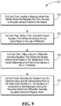
- Figure 7 describes the method 80 performed by the control logic of the disclosed system 10.
- the system 10 determines that a glass sheet is in the appropriate position on the conveyor, the system activates the appropriate camera(s), at 82, to acquire an image of the pattern reflected from the surface of the glass sheet.
- the position of the glass sheets can be determined using conventional sensors.
- one or more additional images may be obtained from each camera, as required, as the glass sheet moves on the conveyor.
- the number of images acquired by each camera is determined by at least two considerations. First, in embodiments of the system wherein the cameras are mounted within an aperture of their associated displays, a sufficient number of images must be acquired to ensure that the system acquires a reflected image of the pattern for all of the points in the viewing area, including those points from which the display pattern is not reflected in a particular image due to the fact that it is located within the area that includes a reflection of the aperture.
- multiple images may be required as the glass is conveyed across the viewing area of the camera in embodiments of the system where the field of view of the camera is not large enough to acquire a reflection of the display pattern from the surface of the glass sheet across its entire first dimension (i.e., the entire height) in one image.
- the system For each of the acquired images, the system, at 86, must determine the precise location in three-space of each point on the surface of the glass sheet based upon the reflected pattern in the image. As previously described, the use of a pattern which is non-repeating in the camera's viewing area ensures that each point on the display screen that is reflected within the viewing area of the camera will be uniquely associated with a pixel that detects the reflected pattern.
- Conventional image processing techniques may be employed to determine the x and y locations (i.e., in the focal plane of the camera) for each point on the surface of the glass sheet that is in the viewing area of the camera for that image. Other known processing techniques may be employed to determine the z location (a.k.a. the elevation) of each point.
- a mapping vector technique is employed (as depicted in figures 8 and 9 , and as more fully described hereinafter) to determine the elevation of each single point on the surface of the glass from the image of the reflected projected pattern.
- the x, y, and z values developed for each point in the viewing area of a particular camera are typically developed in a coordinate system associated with that camera.
- the origin of the coordinate system for each camera is set at that camera's origin 98 (as shown in Figure 8 ).
- the resulting collection of points associated with the surface in the viewing area of each camera (“the point cloud”) may then be combined for each image collected by that camera.
- the system then combines the developed surface data for each of the images acquired from all of the cameras to obtain the surface definition which identifies the location of each point in three-space for the entire surface of the glass sheet.
- the point clouds for each camera are converted to a common ("global") coordinate system, and the point clouds are then combined to form the entire surface.
- one or more other coordinate systems/origins may be selected and employed based upon a particular system's camera/display architecture and/or for computational convenience.
- the combination of the surface developed from the individual acquired images may be performed using other conventional image data processing techniques.
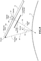
- Figures 8 and 9 illustrate, respectively, the theoretical basis and the method performed by the control logic for determining the elevation (z value) of each point on the surface of the glass from the image of the reflected projected pattern for each acquired image.
- Figure 8 illustrates the pertinent geometrical relationships between the camera 28, the display screen 14, and the surface of the glass sheet G.
- the three principles used to determine the elevation of a single point on the surface of the glass sheet from a reflected projected image are (1) the surface of any object can be defined by the normal vector 92 for each discrete point of the surface; (2) the law of reflection defines the normal vector 92 at each point by bisecting the angle between the incident ray 94 and the reflected ray 96 of light (also referred to herein as the "geometric optical” or “reflection angle” equation); and (3) the normal vector can also be defined by the differential geometry which describes each point on the surface of the glass sheet (also referred to herein as the "differential geometry” equation).
- the incident ray is defined entirely by the camera intrinsics.
- each pixel in the cameras receptor cell at the cameras origin 98 sees a point in space at varying distances through the lens.
- the reflected ray 96 is defined by a screen position and a surface point on the glass. The distance is constrained only where it intersects the incident ray 94.
- mapping vector 100 needs to be established, which defines, for each pixel, where the reflected ray will hit the projected pattern on the display (viewed from the camera origin).
- mapping field i.e., the set of mapping vectors for each pixel in the camera's field of view
- the distances from the camera's origin and each discrete point on the surface can be calculated.
- n ⁇ ⁇ v ⁇ ⁇ m ⁇ ⁇ s v ⁇ v ⁇ ⁇ ⁇ m ⁇ ⁇ s v ⁇ v ⁇ ⁇ v ⁇ v ⁇ v ⁇ ⁇
- n is the surface normal
- v is the camera pixel vector
- m is the mapping vector
- n ⁇ ⁇ p ⁇ ⁇ x ⁇ ⁇ p ⁇ ⁇ y
- Figure 9 illustrates how a suitably programmed computer could implement this mapping vector technique 102.
- the system develops a mapping vector that defines where the reflected ray projects to the display (again, viewed mathematically from the camera origin).
- a first expression, the geometric optical equation, at 106 defines the surface normal vector for each point on the glass sheet surface within the camera's viewing area based upon the law of reflection.
- a second equation, the differential geometry equation, at 108 defines the surface normal vector-based on the multiplication of the partial differentials which describe the point on the surface in the x, y directions.
- mapping vector to obtain the elevation, s (that is, the z distance - the distance between the glass surface and the camera origin) for each point on the glass sheet surface that is within the viewing area of the camera.
- This information coupled with the previously developed x and y locations of each surface point, yields a specific description, in x , y, and z , for each point on the surface.
- the disclosed glass sheet surface data acquisition and surface definition development system 10 may be mounted in-line to inspect glass sheets as they are transported on a conveyor associated with a glass sheet processing system which performs multiple fabricating operations on the glass sheets.
- the disclosed system 10 includes a surface data acquisition system and a computer including logic for receiving the captured image data, and developing a three-dimension description of the glass sheet surface from the image data.
- the system 10 may, as well, perform one or more analyses utilizing the developed surface, such as known optical processing, gaging, and/or other surface related analyses as previously described, and display or otherwise report selected information associated with the analyses.
- computer 42 may be operably connected to the conveyor and cameras to perform the image acquisition, the surface development, and the optical processing described herein. Alternatively, computer 42 may be combined with one or more other computers and/or programmable controls to perform these functions.
- the system 10 may also be programmed by the user to graphically and numerically display characteristics of the surface, including, for example, various indicia of optical distortion and/or gaging, and/or other indicia considered relevant in the industry to the analysis of the quality of formed and fabricated glass sheets.
- the digital cameras 28 ⁇ 40 are each connected via a conventional data line to one or more computers, such as computer 42, which may be suitably programmed to acquire the digital image data from the camera, process the image data to obtain the desired surface definition for the glass sheet, and analyze the data to develop various indicia of distortion.
- the computer 42 may also be programmed to present the developed information in both graphical (e.g., colorcoded images) and statistical forms. If desired, various other statistical data can be derived and reported for predefined areas of the glass sheet.
- the glass sheet surface data acquisition and surface definition development system 10 may additionally or alternatively employ other known image processing techniques to collect and analyze the acquired image data and develop a definition of the surface.
- the displays 14 ⁇ 26 are light boxes that utilize conventional lighting (such as fluorescent lights) behind a translucent panel upon which the contrasting pattern is printed, painted, or otherwise applied using conventional methods.
- the digital cameras 28 - 40 are connected to the computer 60 using known methods, preferably so that the acquisition of the image by the camera may be controlled by the computer 42.
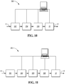
- FIG 10 illustrates a typical glass sheet heating, bending, and tempering system 200 which includes the in-line glass sheet surface data acquisition and surface definition development system 10.
- the glass sheets enter a heating zone 202 where the glass is softened to a temperature suitable for forming the glass into the desired shape.
- the heated glass sheet is then conveyed to a bending station 204 where the softened sheet is formed to the desired shape, and thereafter further conveyed to a cooling station 206 where the glass sheet is cooled in a controlled manner to achieve the appropriate physical characteristics.
- the glass sheet would then be conveyed out of the cooling station onto a conveyor from which the sheet is conveyed for image acquisition and analysis by the disclosed system 10.
- the glass sheet would be moved on the conveyor 12 for further processing.
- transport and conveyance of the glass can be achieved by using known techniques such as by roller, air-float, or belt conveyors, positioners, and robotic arms, in order to handle the glass in the manner described.
- a plurality of conveyors each of which may be independently controlled to move the glass sheets through the different processing stations at speeds to efficiently govern the flow and processing of the glass sheets throughout the system 200.
- Figure 11 similarly schematically illustrates an in-line glass sheet surface data acquisition and surface definition development system 10 in a typical automotive windshield fabrication system 300, which may include a heating station 302, a bending station 304, a cooling station 306, and a lamination station 308, upstream of the optical inspection system 10.
- Selected data output by the system 10 may also be provided as input to the control logic for the associated glass sheet heating, bending, and tempering system 200 (or automotive windshield fabrication system 300) to allow the control(s) associated with one or more of the stations the glass sheet system to modify its (their) operating parameters as a function of the optical data developed from previously processed glass sheets.
- glass sheet surface data acquisition and surface definition development system 10 of the present invention could alternatively be mounted in-line at various other points in the above-described and other glass sheet fabrication systems as desired to maximize the production rate of the system, so long as the optical distortion measurements are taken after the glass sheet has been formed to its final shape.
Landscapes
- Physics & Mathematics (AREA)
- General Physics & Mathematics (AREA)
- Engineering & Computer Science (AREA)
- Computer Vision & Pattern Recognition (AREA)
- Length Measuring Devices By Optical Means (AREA)
- Chemical & Material Sciences (AREA)
- Materials Engineering (AREA)
- Organic Chemistry (AREA)
- Re-Forming, After-Treatment, Cutting And Transporting Of Glass Products (AREA)
Claims (12)
- Système (10) de collecte de données de surface à partir de l'une des surfaces d'une feuille de verre (G) généralement rectangulaire et bombée présentant une surface à considérer avec une première dimension et une seconde dimension, dans lequel la feuille de verre (G) est bombée au moins suivant un ou plusieurs axes de courbure qui sont généralement parallèles à la première dimension, et d'élaboration d'une définition de surface de la feuille de verre (G), le système (10) comprenant :un convoyeur (12) pour déplacer la feuille de verre (G) suivant une première direction généralement parallèle à la première dimension de la feuille de verre (G) ;au moins deux affichages (14-26), chacun des affichages (14-26) projetant un motif de contraste présélectionné,au moins deux caméras (28-40) ; etun pilotage programmable incluant au moins un processeur programmé pour exécuter une logique pour le pilotage de chacune des caméras (28-40) afin de collecter au moins une image du motif réfléchi de l'affichage associé (14-26) sur la feuille de verre lorsque ladite feuille de verre (G) est déplacée et traverse le chemin du motif projeté suivant la première direction, et une logique pour l'analyse et la combinaison des données collectées par les caméras afin de construire des données de surface représentatives de la surface de la feuille de verre (G) ;dans lequel chacune desdites au moins deux caméras (28-40) est appariée de façon unique à l'un des affichages (14-26), dans lequel chacune des paires d'affichage (14-26) et de caméra est montée selon une relation espacée suivant une distance et selon un angle connus par rapport à la surface de la feuille de verre (G) de façon que la caméra détecte l'image réfléchie du motif projeté sur la surface de la feuille de verre (G) provenant de son affichage associé, et dans lequel chacune desdites paires d'affichage et de caméra est espacée l'une de l'autre au moins suivant une seconde direction d'un côté à l'autre de la seconde dimension de la feuille de verre (G) de façon que chaque caméra détecte l'image réfléchie du motif projeté sur la surface de la feuille de verre provenant seulement de son affichage associé, et dans lequel les motifs détectés par les caméras (28-40) couvrent ensemble l'intégralité de la surface suivant la direction de la seconde dimension de la feuille de verre (G).
- Système (10) selon la revendication 1, caractérisé en ce que la première dimension est la dimension la plus petite de la feuille de verre (G) et la seconde dimension est la dimension la plus grande de la feuille de verre.
- Système (10) selon la revendication 1, caractérisé en ce que la logique pour l'analyse et la combinaison des données collectées par les caméras (28-40) afin de construire des données de surface représentatives de la surface de la feuille de verre (G) inclut une logique pour construire des données de surface représentatives de l'intégralité de la surface d'un côté à l'autre de la seconde dimension de la feuille de verre (G).
- Système (10) selon la revendication 1, caractérisé en ce qu'une seule image des motifs réfléchis que projettent les affichages (14-26) et provenant de chacune des caméras (28-40) associées ne peut être combinée afin de définir des données représentatives de la surface de la feuille de verre (G) d'un côté à l'autre de l'intégralité de la seconde dimension de la feuille de verre (G), et dans lequel le pilotage programmable inclut au moins un processeur programmé pour exécuter une logique afin de piloter chacune des caméras (28-40) pour collecter des images multiples du motif réfléchi de l'affichage (14-26) associé sur la feuille de verre lorsque la feuille de verre (G) est déplacée et traverse le chemin du motif projeté suivant la première direction, et une logique pour l'analyse et la combinaison des données collectées par les images multiples collectées par chacune desdites au moins deux caméras (28-40) afin de construire des données de surface représentatives de la surface de la feuille de verre d'un côté à l'autre de l'intégralité de la première dimension de la feuille de verre (G).
- Système (10) selon la revendication 1, caractérisé en ce que chacun des affichages (14-26) inclut une ouverture, et dans lequel la caméra associée est montée derrière son affichage associé de façon que l'axe principal de la caméra associée soit généralement normal à la surface de l'affichage et que l'image soit reçue par la caméra à travers l'ouverture, et dans lequel le pilotage programmable inclut une logique afin de piloter chacune des caméras (28-40) pour collecter des images multiples du motif réfléchi de l'affichage associé sur la feuille de verre (G) lorsque la feuille de verre est déplacée suivant la première direction sur une distance au moins plus grande que la taille de l'ouverture, et une logique pour l'analyse et la combinaison des données provenant des images multiples afin de définir des données représentatives de la surface de la feuille de verre (G) dans la zone pour laquelle l'une quelconque des images collectées inclut une image réfléchie de l'ouverture.
- Système (10) selon la revendication 1, caractérisé en ce que la logique pour l'analyse et la combinaison des données collectées par les caméras (28-40) pour construire des données de surface représentatives de la surface de la feuille de verre (G) inclut au moins :une logique pour l'élaboration, pour chaque pixel de la zone d'observation de la caméra pour chaque image collectée, d'un vecteur de modélisation (100) qui définit l'endroit où le rayon réfléchi est projeté à partir de l'origine de la caméra vers l'affichage associé ; etune logique pour l'élaboration, pour chaque pixel de la zone d'observation de la caméra pour chaque image collectée, de la valeur en élévation, s, de ce point, en résolvant simultanément (1) l'équation de géométrie optique et (2) l'équation de géométrie différentielle, à l'aide du vecteur de modélisation (100).
- Système (10) selon la revendication 1, caractérisé en ce que le motif de contraste présélectionné n'est pas répétitif sur l'intégralité de la zone d'observation de la caméra.
- Système (10) selon la revendication 7, caractérisé en ce que le motif de contraste présélectionné est un motif à trois fréquences, construit par la superposition de trois différents motifs sinusoïdaux de fréquence suivant chacune des directions x et y du système de coordonnées utilisé par la logique du système.
- Système (10) selon la revendication 7, caractérisé en ce que le motif de contraste présélectionné est un motif à deux fréquences, construit par la superposition de deux différents motifs sinusoïdaux de fréquence suivant chacune des directions x et y du motif, où les deux différents motifs sinusoïdaux de fréquences sont pivotés par rapport aux axes du système de coordonnées utilisé par la logique du système.
- Système (10) selon la revendication 1, caractérisé en ce que ledit système est incorporé dans un système de fabrication de feuilles de verre bombées (G) incluant de multiples postes de transformation et un ou plusieurs convoyeurs (12) pour déplacer la feuille de verre (G) de poste en poste au cours de la transformation.
- Procédé de collecte de données de surface à partir d'une feuille de verre bombée (G) et d'élaboration d'une définition de surface de ladite feuille de verre, ladite feuille de verre (G) présentant une première dimension et une seconde dimension, dans lequel la feuille de verre (G) est bombée au moins suivant un ou plusieurs axes de courbure qui sont généralement parallèles à la première dimension, le procédé incluant au moins les étapes de :déplacement de la feuille de verre (G) suivant une première direction généralement parallèle à la première dimension de la feuille de verre ;projection d'un motif de contraste présélectionné provenant de chacun desdits au moins deux affichages (14-26) sur la surface de la feuille de verre (G)apport d'au moins deux caméras (28-40) ;pilotage de chacune des caméras (28-40) afin de collecter au moins une image du motif réfléchi d'un affichage associé parmi lesdits au moins deux affichages (14-26) sur la feuille de verre (G) lorsque la feuille de verre (G) est déplacée et traverse le chemin du motif projeté suivant la première direction ; etanalyse et combinaison des données collectées par les caméras (28-40) afin de construire des données de surface représentatives de la surface de la feuille de verre (G) ;dans lequel l'étape de l'apport des caméras inclut uniquement d'apparier chacune des caméras à l'un des affichages (14-26), et de monter chacune des paires de caméra et d'affichage selon une relation espacée suivant une distance et un angle connus par rapport à la surface de la feuille de verre (G) afin de détecter l'image réfléchie du motif projeté sur la surface de la feuille de verre (G) provenant de son affichage associé, et d'espacer l'une de l'autre chacune des paires d'affichage et de caméra au moins suivant une seconde direction d'un côté à l'autre de la seconde dimension de la feuille de verre (G) de façon que chaque caméra détecte l'image réfléchie du motif projeté sur la surface de la feuille de verre (G) provenant seulement de son affichage associé, dans lequel les motifs détectés par les caméras (28-40) couvrent ensemble l'intégralité de la surface suivant la direction de la seconde dimension de la feuille de verre (G).
- Procédé selon la revendication 11 caractérisé en ce que l'étape d'analyse et de combinaison des données collectées par les caméras (28-40) afin de construire des données de surface représentatives de la surface de la feuille de verre (G) inclut en outre au moins les étapes de :élaboration, pour chaque pixel dans la zone de d'observation de la caméra pour chaque image collectée, d'un vecteur de modélisation (100) qui définit où le rayon réfléchi est projeté depuis l'origine de la caméra vers l'affichage associé, etélaboration, pour chaque pixel dans la zone de d'observation de la caméra pour chaque image collectée, de la valeur en élévation, s, de ce point, en résolvant simultanément (1) l'équation de géométrie optique et (2) l'équation de géométrie différentielle, à l'aide du vecteur de modélisation (100).
Priority Applications (1)
| Application Number | Priority Date | Filing Date | Title |
|---|---|---|---|
| PL16814894T PL3314237T3 (pl) | 2015-06-26 | 2016-05-17 | System i sposób opracowywania trójwymiarowych informacji o powierzchni odpowiadających wyprofilowanej tafli szkła |
Applications Claiming Priority (2)
| Application Number | Priority Date | Filing Date | Title |
|---|---|---|---|
| US14/752,133 US9841276B2 (en) | 2015-06-26 | 2015-06-26 | System and method for developing three-dimensional surface information corresponding to a contoured glass sheet |
| PCT/US2016/032855 WO2016209414A1 (fr) | 2015-06-26 | 2016-05-17 | Système et procédé pour le développement d'informations de surface en trois dimensions correspondant à une feuille de verre profilée |
Publications (3)
| Publication Number | Publication Date |
|---|---|
| EP3314237A1 EP3314237A1 (fr) | 2018-05-02 |
| EP3314237A4 EP3314237A4 (fr) | 2019-03-27 |
| EP3314237B1 true EP3314237B1 (fr) | 2021-11-03 |
Family
ID=57585430
Family Applications (1)
| Application Number | Title | Priority Date | Filing Date |
|---|---|---|---|
| EP16814894.8A Active EP3314237B1 (fr) | 2015-06-26 | 2016-05-17 | Système et procédé pour le développement d'informations de surface en trois dimensions correspondant à une feuille de verre profilée |
Country Status (10)
| Country | Link |
|---|---|
| US (1) | US9841276B2 (fr) |
| EP (1) | EP3314237B1 (fr) |
| CN (1) | CN107709971B (fr) |
| BR (1) | BR112017028029B1 (fr) |
| CA (1) | CA2990385A1 (fr) |
| ES (1) | ES2898407T3 (fr) |
| HU (1) | HUE056572T2 (fr) |
| MX (1) | MX2017017056A (fr) |
| PL (1) | PL3314237T3 (fr) |
| WO (1) | WO2016209414A1 (fr) |
Families Citing this family (9)
| Publication number | Priority date | Publication date | Assignee | Title |
|---|---|---|---|---|
| US9952039B2 (en) | 2015-06-26 | 2018-04-24 | Glasstech, Inc. | System and method for measuring reflected optical distortion in contoured panels having specular surfaces |
| US9470641B1 (en) | 2015-06-26 | 2016-10-18 | Glasstech, Inc. | System and method for measuring reflected optical distortion in contoured glass sheets |
| US9933251B2 (en) | 2015-06-26 | 2018-04-03 | Glasstech, Inc. | Non-contact gaging system and method for contoured glass sheets |
| US9952037B2 (en) | 2015-06-26 | 2018-04-24 | Glasstech, Inc. | System and method for developing three-dimensional surface information corresponding to a contoured sheet |
| US9851200B2 (en) | 2015-06-26 | 2017-12-26 | Glasstech, Inc. | Non-contact gaging system and method for contoured panels having specular surfaces |
| US10289930B2 (en) * | 2017-02-09 | 2019-05-14 | Glasstech, Inc. | System and associated for online measurement of the optical characteristics of a glass sheet |
| CN109238118B (zh) * | 2018-11-06 | 2024-02-27 | 桂林电子科技大学 | 一种检测玻璃可装配性的检测系统及方法 |
| CN110351481A (zh) * | 2019-06-20 | 2019-10-18 | 浙江四点灵机器人股份有限公司 | 一种曲面玻璃成像系统及方法 |
| CN115180810B (zh) * | 2022-08-15 | 2023-08-29 | 洛阳北方玻璃技术股份有限公司 | 玻璃在冷却风栅中进行双向复合运动的轨迹控制方法 |
Family Cites Families (51)
| Publication number | Priority date | Publication date | Assignee | Title |
|---|---|---|---|---|
| US4585343A (en) | 1983-11-04 | 1986-04-29 | Libbey-Owens-Ford Company | Apparatus and method for inspecting glass |
| US4629319A (en) | 1984-02-14 | 1986-12-16 | Diffracto Ltd. | Panel surface flaw inspection |
| US4989984A (en) | 1989-11-08 | 1991-02-05 | Environmental Research Institute Of Michigan | System for measuring optical characteristics of curved surfaces |
| US5574274A (en) | 1995-02-21 | 1996-11-12 | Microtek International, Inc. | Transmissive/reflective optical scanning apparatus |
| DE19643018B4 (de) | 1996-10-18 | 2010-06-17 | Isra Surface Vision Gmbh | Verfahren und Vorrichtung zum Messen des Verlaufs reflektierender Oberflächen |
| US6031221A (en) | 1998-02-19 | 2000-02-29 | Emhart Glass S.A. | Container inspection machine |
| US6100990A (en) | 1999-06-14 | 2000-08-08 | Ford Motor Company | Method and apparatus for determining reflective optical quality using gray-scale patterns |
| US6512239B1 (en) | 2000-06-27 | 2003-01-28 | Photon Dynamics Canada Inc. | Stereo vision inspection system for transparent media |
| AU2001288641A1 (en) | 2000-09-01 | 2002-03-13 | Mark M. Abbott | Optical system for imaging distortions in moving reflective sheets |
| FR2817042B1 (fr) | 2000-11-22 | 2003-06-20 | Saint Gobain | Procede et dispositif d'analyse de la surface d'un substrat |
| DE10127304C5 (de) | 2001-06-06 | 2007-07-19 | Technische Universität Carolo-Wilhelmina Zu Braunschweig | Verfahren und Vorrichtung zur Bestimmung der dreidimensionalen Kontur einer spiegelnden Oberfläche eines Objektes |
| US7106325B2 (en) | 2001-08-03 | 2006-09-12 | Hewlett-Packard Development Company, L.P. | System and method for rendering digital images having surface reflectance properties |
| US6985231B2 (en) | 2001-09-20 | 2006-01-10 | Strainoptics, Inc. | Method and apparatus for measuring the optical quality of a reflective surface |
| EP1601928B1 (fr) | 2003-03-07 | 2015-09-02 | International Industry Support, Inc. | Systeme de balayage au moyen d'un ensemble camera stereo |
| US8224064B1 (en) | 2003-05-21 | 2012-07-17 | University Of Kentucky Research Foundation, Inc. | System and method for 3D imaging using structured light illumination |
| JP4036268B2 (ja) | 2004-08-06 | 2008-01-23 | 国立大学法人東北大学 | 超低膨張ガラス材料の線膨張係数評価方法 |
| JP4626982B2 (ja) | 2005-02-10 | 2011-02-09 | セントラル硝子株式会社 | ガラス板の端面の欠陥検出装置および検出方法 |
| US8254659B2 (en) | 2005-09-09 | 2012-08-28 | Sacmi Cooperativa Meccanici Imolasocieta Cooperativa | Method and apparatus for visually inspecting an object |
| JP5156152B2 (ja) | 2005-10-17 | 2013-03-06 | アイ2アイシー コーポレイション | 組み合わせ型の映像ディスプレイおよびカメラシステム |
| DE102005050882B4 (de) | 2005-10-21 | 2008-04-30 | Isra Vision Systems Ag | System und Verfahren zur optischen Inspektion von Glasscheiben |
| CN101466998B (zh) | 2005-11-09 | 2015-09-16 | 几何信息学股份有限公司 | 三维绝对坐标表面成像的方法和装置 |
| US8358354B2 (en) | 2009-01-26 | 2013-01-22 | The Board Of Trustees Of The Leland Stanford Junior University | Correction of optical abberations |
| DE102006015792A1 (de) | 2006-04-05 | 2007-10-18 | Isra Surface Vision Gmbh | Verfahren und System zur Formmessung einer reflektierenden Oberfläche |
| TWI397995B (zh) * | 2006-04-17 | 2013-06-01 | Omnivision Tech Inc | 陣列成像系統及其相關方法 |
| JP4174536B2 (ja) | 2006-08-24 | 2008-11-05 | アドバンスド・マスク・インスペクション・テクノロジー株式会社 | 画像補正装置、画像検査装置、及び画像補正方法 |
| US7471383B2 (en) | 2006-12-19 | 2008-12-30 | Pilkington North America, Inc. | Method of automated quantitative analysis of distortion in shaped vehicle glass by reflected optical imaging |
| CA2675456C (fr) | 2007-01-12 | 2017-03-07 | Synergx Technologies Inc. | Canaux a fond clair et a fond sombre, utilises pour des systemes d'inspection de vitre d'automobile |
| US8355581B2 (en) | 2007-03-06 | 2013-01-15 | Advanced Vision Technology (Avt) Ltd. | System and method for detecting the contour of an object on a moving conveyor belt |
| US8126273B2 (en) | 2007-04-05 | 2012-02-28 | Siemens Corporation | Method for reconstructing three-dimensional images from two-dimensional image data |
| DE102007031244B3 (de) | 2007-07-05 | 2009-01-02 | Fraunhofer-Gesellschaft zur Förderung der angewandten Forschung e.V. | Vorrichtung und Verfahren zur Durchführung statischer und dynamischer Streulichtmessungen in kleinen Volumina |
| JP2011512533A (ja) * | 2008-02-15 | 2011-04-21 | ピルキングトン・グループ・リミテッド | 反射光学画像法によるガラス表面形状及び光学歪の測定方法 |
| FR2930030B1 (fr) | 2008-04-11 | 2012-12-28 | Visuol Technologies | Dispositif de controle de la qualite d'une surface |
| US8049879B2 (en) | 2008-04-15 | 2011-11-01 | Glasstech, Inc. | Method and apparatus for measuring transmitted optical distortion in glass sheets |
| FR2936605B1 (fr) | 2008-10-01 | 2014-10-31 | Saint Gobain | Dispositif d'analyse de la surface d'un substrat |
| US8292394B2 (en) * | 2009-06-05 | 2012-10-23 | Canon Kabushiki Kaisha | Inkjet recording apparatus |
| US8670031B2 (en) | 2009-09-22 | 2014-03-11 | Cyberoptics Corporation | High speed optical inspection system with camera array and compact, integrated illuminator |
| FR2960059B1 (fr) | 2010-05-11 | 2012-12-28 | Visuol Technologies | Installation de controle de la qualite d'une surface d'un objet |
| US8532812B2 (en) | 2010-06-29 | 2013-09-10 | Mitsubishi Electric Research Laboratories, Inc. | System and method for identifying defects of surfaces due to machining processes |
| JP5639797B2 (ja) | 2010-07-01 | 2014-12-10 | 株式会社日立ハイテクノロジーズ | パターンマッチング方法,画像処理装置、及びコンピュータプログラム |
| US9056584B2 (en) * | 2010-07-08 | 2015-06-16 | Gentex Corporation | Rearview assembly for a vehicle |
| US20120098959A1 (en) | 2010-10-20 | 2012-04-26 | Glasstech, Inc. | Method and apparatus for measuring transmitted optical distortion in glass sheets |
| FR2975776B1 (fr) | 2011-05-24 | 2014-03-28 | Visuol Technologies | Installation pour le controle de la qualite d'une surface d'un objet |
| US9322643B2 (en) | 2011-10-18 | 2016-04-26 | Nanyang Technological University | Apparatus and method for 3D surface measurement |
| US10037474B2 (en) * | 2013-03-15 | 2018-07-31 | Leap Motion, Inc. | Determining the relative locations of multiple motion-tracking devices |
| CN203231736U (zh) * | 2013-04-18 | 2013-10-09 | 中国科学院沈阳自动化研究所 | 一种基于双目视觉的镜面物体测量装置 |
| US9896369B2 (en) * | 2014-11-24 | 2018-02-20 | Glasstech, Inc. | Glass sheet forming and annealing providing edge stress control |
| US9952037B2 (en) | 2015-06-26 | 2018-04-24 | Glasstech, Inc. | System and method for developing three-dimensional surface information corresponding to a contoured sheet |
| US9470641B1 (en) | 2015-06-26 | 2016-10-18 | Glasstech, Inc. | System and method for measuring reflected optical distortion in contoured glass sheets |
| US9952039B2 (en) | 2015-06-26 | 2018-04-24 | Glasstech, Inc. | System and method for measuring reflected optical distortion in contoured panels having specular surfaces |
| US9933251B2 (en) | 2015-06-26 | 2018-04-03 | Glasstech, Inc. | Non-contact gaging system and method for contoured glass sheets |
| US9851200B2 (en) | 2015-06-26 | 2017-12-26 | Glasstech, Inc. | Non-contact gaging system and method for contoured panels having specular surfaces |
-
2015
- 2015-06-26 US US14/752,133 patent/US9841276B2/en active Active
-
2016
- 2016-05-17 CN CN201680037574.3A patent/CN107709971B/zh active Active
- 2016-05-17 WO PCT/US2016/032855 patent/WO2016209414A1/fr active Application Filing
- 2016-05-17 PL PL16814894T patent/PL3314237T3/pl unknown
- 2016-05-17 ES ES16814894T patent/ES2898407T3/es active Active
- 2016-05-17 BR BR112017028029-9A patent/BR112017028029B1/pt active IP Right Grant
- 2016-05-17 EP EP16814894.8A patent/EP3314237B1/fr active Active
- 2016-05-17 HU HUE16814894A patent/HUE056572T2/hu unknown
- 2016-05-17 CA CA2990385A patent/CA2990385A1/fr not_active Abandoned
- 2016-05-17 MX MX2017017056A patent/MX2017017056A/es unknown
Also Published As
| Publication number | Publication date |
|---|---|
| CA2990385A1 (fr) | 2016-12-29 |
| US20160377419A1 (en) | 2016-12-29 |
| CN107709971A (zh) | 2018-02-16 |
| PL3314237T3 (pl) | 2022-02-14 |
| EP3314237A4 (fr) | 2019-03-27 |
| WO2016209414A1 (fr) | 2016-12-29 |
| US9841276B2 (en) | 2017-12-12 |
| CN107709971B (zh) | 2021-04-06 |
| BR112017028029A2 (pt) | 2018-08-28 |
| ES2898407T3 (es) | 2022-03-07 |
| HUE056572T2 (hu) | 2022-02-28 |
| BR112017028029B1 (pt) | 2021-06-15 |
| MX2017017056A (es) | 2018-05-23 |
| EP3314237A1 (fr) | 2018-05-02 |
Similar Documents
| Publication | Publication Date | Title |
|---|---|---|
| US9846129B2 (en) | System and method for measuring reflected optical distortion in contoured glass sheets | |
| EP3314237B1 (fr) | Système et procédé pour le développement d'informations de surface en trois dimensions correspondant à une feuille de verre profilée | |
| US9952037B2 (en) | System and method for developing three-dimensional surface information corresponding to a contoured sheet | |
| US9952039B2 (en) | System and method for measuring reflected optical distortion in contoured panels having specular surfaces | |
| US9851200B2 (en) | Non-contact gaging system and method for contoured panels having specular surfaces | |
| US10267750B2 (en) | System and associated method for online detection of small defects on/in a glass sheet | |
| US10289930B2 (en) | System and associated for online measurement of the optical characteristics of a glass sheet | |
| US9933251B2 (en) | Non-contact gaging system and method for contoured glass sheets | |
| US20160109363A1 (en) | Method for determining the refractive power of a transparent object, and corresponding device |
Legal Events
| Date | Code | Title | Description |
|---|---|---|---|
| STAA | Information on the status of an ep patent application or granted ep patent |
Free format text: STATUS: THE INTERNATIONAL PUBLICATION HAS BEEN MADE |
|
| PUAI | Public reference made under article 153(3) epc to a published international application that has entered the european phase |
Free format text: ORIGINAL CODE: 0009012 |
|
| STAA | Information on the status of an ep patent application or granted ep patent |
Free format text: STATUS: REQUEST FOR EXAMINATION WAS MADE |
|
| 17P | Request for examination filed |
Effective date: 20171221 |
|
| AK | Designated contracting states |
Kind code of ref document: A1 Designated state(s): AL AT BE BG CH CY CZ DE DK EE ES FI FR GB GR HR HU IE IS IT LI LT LU LV MC MK MT NL NO PL PT RO RS SE SI SK SM TR |
|
| AX | Request for extension of the european patent |
Extension state: BA ME |
|
| RIN1 | Information on inventor provided before grant (corrected) |
Inventor name: MORAN, BENJAMIN L. Inventor name: ADDINGTON, JASON C. Inventor name: VILD, MICHAEL J. |
|
| DAV | Request for validation of the european patent (deleted) | ||
| DAX | Request for extension of the european patent (deleted) | ||
| A4 | Supplementary search report drawn up and despatched |
Effective date: 20190225 |
|
| RIC1 | Information provided on ipc code assigned before grant |
Ipc: C03B 11/08 20060101ALI20190219BHEP Ipc: G01N 1/04 20060101ALI20190219BHEP Ipc: G01B 11/25 20060101ALI20190219BHEP Ipc: G01N 21/00 20060101AFI20190219BHEP |
|
| REG | Reference to a national code |
Ref country code: DE Ref legal event code: R079 Ref document number: 602016065794 Country of ref document: DE Free format text: PREVIOUS MAIN CLASS: G01N0021000000 Ipc: G01B0011245000 |
|
| GRAP | Despatch of communication of intention to grant a patent |
Free format text: ORIGINAL CODE: EPIDOSNIGR1 |
|
| STAA | Information on the status of an ep patent application or granted ep patent |
Free format text: STATUS: GRANT OF PATENT IS INTENDED |
|
| RIC1 | Information provided on ipc code assigned before grant |
Ipc: C03B 29/02 20060101ALN20210511BHEP Ipc: C03B 27/04 20060101ALN20210511BHEP Ipc: C03B 23/023 20060101ALN20210511BHEP Ipc: C03B 35/14 20060101ALN20210511BHEP Ipc: G01N 1/04 20060101ALI20210511BHEP Ipc: G01N 21/00 20060101ALI20210511BHEP Ipc: G01B 11/25 20060101ALI20210511BHEP Ipc: G01B 11/245 20060101AFI20210511BHEP |
|
| RIC1 | Information provided on ipc code assigned before grant |
Ipc: C03B 29/02 20060101ALN20210517BHEP Ipc: C03B 27/04 20060101ALN20210517BHEP Ipc: C03B 23/023 20060101ALN20210517BHEP Ipc: C03B 35/14 20060101ALN20210517BHEP Ipc: G01N 1/04 20060101ALI20210517BHEP Ipc: G01N 21/00 20060101ALI20210517BHEP Ipc: G01B 11/25 20060101ALI20210517BHEP Ipc: G01B 11/245 20060101AFI20210517BHEP |
|
| RIC1 | Information provided on ipc code assigned before grant |
Ipc: C03B 29/02 20060101ALN20210529BHEP Ipc: C03B 27/04 20060101ALN20210529BHEP Ipc: C03B 23/023 20060101ALN20210529BHEP Ipc: C03B 35/14 20060101ALN20210529BHEP Ipc: G01N 1/04 20060101ALI20210529BHEP Ipc: G01N 21/00 20060101ALI20210529BHEP Ipc: G01B 11/25 20060101ALI20210529BHEP Ipc: G01B 11/245 20060101AFI20210529BHEP |
|
| INTG | Intention to grant announced |
Effective date: 20210615 |
|
| GRAS | Grant fee paid |
Free format text: ORIGINAL CODE: EPIDOSNIGR3 |
|
| GRAA | (expected) grant |
Free format text: ORIGINAL CODE: 0009210 |
|
| STAA | Information on the status of an ep patent application or granted ep patent |
Free format text: STATUS: THE PATENT HAS BEEN GRANTED |
|
| AK | Designated contracting states |
Kind code of ref document: B1 Designated state(s): AL AT BE BG CH CY CZ DE DK EE ES FI FR GB GR HR HU IE IS IT LI LT LU LV MC MK MT NL NO PL PT RO RS SE SI SK SM TR |
|
| REG | Reference to a national code |
Ref country code: GB Ref legal event code: FG4D |
|
| REG | Reference to a national code |
Ref country code: AT Ref legal event code: REF Ref document number: 1444334 Country of ref document: AT Kind code of ref document: T Effective date: 20211115 Ref country code: CH Ref legal event code: EP |
|
| REG | Reference to a national code |
Ref country code: IE Ref legal event code: FG4D |
|
| REG | Reference to a national code |
Ref country code: DE Ref legal event code: R096 Ref document number: 602016065794 Country of ref document: DE |
|
| REG | Reference to a national code |
Ref country code: FI Ref legal event code: FGE |
|
| REG | Reference to a national code |
Ref country code: LT Ref legal event code: MG9D |
|
| REG | Reference to a national code |
Ref country code: HU Ref legal event code: AG4A Ref document number: E056572 Country of ref document: HU |
|
| REG | Reference to a national code |
Ref country code: ES Ref legal event code: FG2A Ref document number: 2898407 Country of ref document: ES Kind code of ref document: T3 Effective date: 20220307 |
|
| REG | Reference to a national code |
Ref country code: NL Ref legal event code: MP Effective date: 20211103 |
|
| REG | Reference to a national code |
Ref country code: AT Ref legal event code: MK05 Ref document number: 1444334 Country of ref document: AT Kind code of ref document: T Effective date: 20211103 |
|
| PG25 | Lapsed in a contracting state [announced via postgrant information from national office to epo] |
Ref country code: RS Free format text: LAPSE BECAUSE OF FAILURE TO SUBMIT A TRANSLATION OF THE DESCRIPTION OR TO PAY THE FEE WITHIN THE PRESCRIBED TIME-LIMIT Effective date: 20211103 Ref country code: LT Free format text: LAPSE BECAUSE OF FAILURE TO SUBMIT A TRANSLATION OF THE DESCRIPTION OR TO PAY THE FEE WITHIN THE PRESCRIBED TIME-LIMIT Effective date: 20211103 Ref country code: AT Free format text: LAPSE BECAUSE OF FAILURE TO SUBMIT A TRANSLATION OF THE DESCRIPTION OR TO PAY THE FEE WITHIN THE PRESCRIBED TIME-LIMIT Effective date: 20211103 |
|
| PG25 | Lapsed in a contracting state [announced via postgrant information from national office to epo] |
Ref country code: IS Free format text: LAPSE BECAUSE OF FAILURE TO SUBMIT A TRANSLATION OF THE DESCRIPTION OR TO PAY THE FEE WITHIN THE PRESCRIBED TIME-LIMIT Effective date: 20220303 Ref country code: SE Free format text: LAPSE BECAUSE OF FAILURE TO SUBMIT A TRANSLATION OF THE DESCRIPTION OR TO PAY THE FEE WITHIN THE PRESCRIBED TIME-LIMIT Effective date: 20211103 Ref country code: PT Free format text: LAPSE BECAUSE OF FAILURE TO SUBMIT A TRANSLATION OF THE DESCRIPTION OR TO PAY THE FEE WITHIN THE PRESCRIBED TIME-LIMIT Effective date: 20220303 Ref country code: NO Free format text: LAPSE BECAUSE OF FAILURE TO SUBMIT A TRANSLATION OF THE DESCRIPTION OR TO PAY THE FEE WITHIN THE PRESCRIBED TIME-LIMIT Effective date: 20220203 Ref country code: NL Free format text: LAPSE BECAUSE OF FAILURE TO SUBMIT A TRANSLATION OF THE DESCRIPTION OR TO PAY THE FEE WITHIN THE PRESCRIBED TIME-LIMIT Effective date: 20211103 Ref country code: LV Free format text: LAPSE BECAUSE OF FAILURE TO SUBMIT A TRANSLATION OF THE DESCRIPTION OR TO PAY THE FEE WITHIN THE PRESCRIBED TIME-LIMIT Effective date: 20211103 Ref country code: HR Free format text: LAPSE BECAUSE OF FAILURE TO SUBMIT A TRANSLATION OF THE DESCRIPTION OR TO PAY THE FEE WITHIN THE PRESCRIBED TIME-LIMIT Effective date: 20211103 Ref country code: GR Free format text: LAPSE BECAUSE OF FAILURE TO SUBMIT A TRANSLATION OF THE DESCRIPTION OR TO PAY THE FEE WITHIN THE PRESCRIBED TIME-LIMIT Effective date: 20220204 |
|
| PG25 | Lapsed in a contracting state [announced via postgrant information from national office to epo] |
Ref country code: SM Free format text: LAPSE BECAUSE OF FAILURE TO SUBMIT A TRANSLATION OF THE DESCRIPTION OR TO PAY THE FEE WITHIN THE PRESCRIBED TIME-LIMIT Effective date: 20211103 Ref country code: SK Free format text: LAPSE BECAUSE OF FAILURE TO SUBMIT A TRANSLATION OF THE DESCRIPTION OR TO PAY THE FEE WITHIN THE PRESCRIBED TIME-LIMIT Effective date: 20211103 Ref country code: EE Free format text: LAPSE BECAUSE OF FAILURE TO SUBMIT A TRANSLATION OF THE DESCRIPTION OR TO PAY THE FEE WITHIN THE PRESCRIBED TIME-LIMIT Effective date: 20211103 Ref country code: DK Free format text: LAPSE BECAUSE OF FAILURE TO SUBMIT A TRANSLATION OF THE DESCRIPTION OR TO PAY THE FEE WITHIN THE PRESCRIBED TIME-LIMIT Effective date: 20211103 |
|
| REG | Reference to a national code |
Ref country code: DE Ref legal event code: R097 Ref document number: 602016065794 Country of ref document: DE |
|
| PLBE | No opposition filed within time limit |
Free format text: ORIGINAL CODE: 0009261 |
|
| STAA | Information on the status of an ep patent application or granted ep patent |
Free format text: STATUS: NO OPPOSITION FILED WITHIN TIME LIMIT |
|
| 26N | No opposition filed |
Effective date: 20220804 |
|
| PG25 | Lapsed in a contracting state [announced via postgrant information from national office to epo] |
Ref country code: AL Free format text: LAPSE BECAUSE OF FAILURE TO SUBMIT A TRANSLATION OF THE DESCRIPTION OR TO PAY THE FEE WITHIN THE PRESCRIBED TIME-LIMIT Effective date: 20211103 |
|
| PG25 | Lapsed in a contracting state [announced via postgrant information from national office to epo] |
Ref country code: SI Free format text: LAPSE BECAUSE OF FAILURE TO SUBMIT A TRANSLATION OF THE DESCRIPTION OR TO PAY THE FEE WITHIN THE PRESCRIBED TIME-LIMIT Effective date: 20211103 |
|
| REG | Reference to a national code |
Ref country code: CH Ref legal event code: PL |
|
| PG25 | Lapsed in a contracting state [announced via postgrant information from national office to epo] |
Ref country code: MC Free format text: LAPSE BECAUSE OF FAILURE TO SUBMIT A TRANSLATION OF THE DESCRIPTION OR TO PAY THE FEE WITHIN THE PRESCRIBED TIME-LIMIT Effective date: 20211103 Ref country code: LI Free format text: LAPSE BECAUSE OF NON-PAYMENT OF DUE FEES Effective date: 20220531 Ref country code: CH Free format text: LAPSE BECAUSE OF NON-PAYMENT OF DUE FEES Effective date: 20220531 |
|
| PG25 | Lapsed in a contracting state [announced via postgrant information from national office to epo] |
Ref country code: IE Free format text: LAPSE BECAUSE OF NON-PAYMENT OF DUE FEES Effective date: 20220517 |
|
| P01 | Opt-out of the competence of the unified patent court (upc) registered |
Effective date: 20230530 |
|
| PGFP | Annual fee paid to national office [announced via postgrant information from national office to epo] |
Ref country code: IT Payment date: 20230519 Year of fee payment: 8 |
|
| PG25 | Lapsed in a contracting state [announced via postgrant information from national office to epo] |
Ref country code: MK Free format text: LAPSE BECAUSE OF FAILURE TO SUBMIT A TRANSLATION OF THE DESCRIPTION OR TO PAY THE FEE WITHIN THE PRESCRIBED TIME-LIMIT Effective date: 20211103 Ref country code: CY Free format text: LAPSE BECAUSE OF FAILURE TO SUBMIT A TRANSLATION OF THE DESCRIPTION OR TO PAY THE FEE WITHIN THE PRESCRIBED TIME-LIMIT Effective date: 20211103 |
|
| PGFP | Annual fee paid to national office [announced via postgrant information from national office to epo] |
Ref country code: LU Payment date: 20240527 Year of fee payment: 9 |
|
| PG25 | Lapsed in a contracting state [announced via postgrant information from national office to epo] |
Ref country code: TR Free format text: LAPSE BECAUSE OF FAILURE TO SUBMIT A TRANSLATION OF THE DESCRIPTION OR TO PAY THE FEE WITHIN THE PRESCRIBED TIME-LIMIT Effective date: 20211103 |
|
| PGFP | Annual fee paid to national office [announced via postgrant information from national office to epo] |
Ref country code: GB Payment date: 20240527 Year of fee payment: 9 |
|
| PGFP | Annual fee paid to national office [announced via postgrant information from national office to epo] |
Ref country code: DE Payment date: 20240530 Year of fee payment: 9 |
|
| PGFP | Annual fee paid to national office [announced via postgrant information from national office to epo] |
Ref country code: ES Payment date: 20240603 Year of fee payment: 9 |
|
| PGFP | Annual fee paid to national office [announced via postgrant information from national office to epo] |
Ref country code: CZ Payment date: 20240507 Year of fee payment: 9 |
|
| PGFP | Annual fee paid to national office [announced via postgrant information from national office to epo] |
Ref country code: RO Payment date: 20240507 Year of fee payment: 9 Ref country code: FR Payment date: 20240527 Year of fee payment: 9 Ref country code: FI Payment date: 20240527 Year of fee payment: 9 Ref country code: BG Payment date: 20240510 Year of fee payment: 9 |
|
| PGFP | Annual fee paid to national office [announced via postgrant information from national office to epo] |
Ref country code: PL Payment date: 20240507 Year of fee payment: 9 |
|
| PGFP | Annual fee paid to national office [announced via postgrant information from national office to epo] |
Ref country code: HU Payment date: 20240509 Year of fee payment: 9 Ref country code: BE Payment date: 20240527 Year of fee payment: 9 |