EP3314048B1 - Kettengewirk mit schussfäden mit variablem weg - Google Patents
Kettengewirk mit schussfäden mit variablem weg Download PDFInfo
- Publication number
- EP3314048B1 EP3314048B1 EP16738585.5A EP16738585A EP3314048B1 EP 3314048 B1 EP3314048 B1 EP 3314048B1 EP 16738585 A EP16738585 A EP 16738585A EP 3314048 B1 EP3314048 B1 EP 3314048B1
- Authority
- EP
- European Patent Office
- Prior art keywords
- strands
- weft
- fabric
- warp
- strand
- Prior art date
- Legal status (The legal status is an assumption and is not a legal conclusion. Google has not performed a legal analysis and makes no representation as to the accuracy of the status listed.)
- Active
Links
Images



Classifications
-
- D—TEXTILES; PAPER
- D04—BRAIDING; LACE-MAKING; KNITTING; TRIMMINGS; NON-WOVEN FABRICS
- D04B—KNITTING
- D04B21/00—Warp knitting processes for the production of fabrics or articles not dependent on the use of particular machines; Fabrics or articles defined by such processes
- D04B21/06—Patterned fabrics or articles
- D04B21/08—Patterned fabrics or articles characterised by thread material
-
- D—TEXTILES; PAPER
- D04—BRAIDING; LACE-MAKING; KNITTING; TRIMMINGS; NON-WOVEN FABRICS
- D04B—KNITTING
- D04B21/00—Warp knitting processes for the production of fabrics or articles not dependent on the use of particular machines; Fabrics or articles defined by such processes
- D04B21/06—Patterned fabrics or articles
-
- D—TEXTILES; PAPER
- D04—BRAIDING; LACE-MAKING; KNITTING; TRIMMINGS; NON-WOVEN FABRICS
- D04B—KNITTING
- D04B21/00—Warp knitting processes for the production of fabrics or articles not dependent on the use of particular machines; Fabrics or articles defined by such processes
- D04B21/14—Fabrics characterised by the incorporation by knitting, in one or more thread, fleece, or fabric layers, of reinforcing, binding, or decorative threads; Fabrics incorporating small auxiliary elements, e.g. for decorative purposes
-
- D—TEXTILES; PAPER
- D04—BRAIDING; LACE-MAKING; KNITTING; TRIMMINGS; NON-WOVEN FABRICS
- D04B—KNITTING
- D04B23/00—Flat warp knitting machines
- D04B23/22—Flat warp knitting machines with special thread-guiding means
-
- D—TEXTILES; PAPER
- D04—BRAIDING; LACE-MAKING; KNITTING; TRIMMINGS; NON-WOVEN FABRICS
- D04B—KNITTING
- D04B27/00—Details of, or auxiliary devices incorporated in, warp knitting machines, restricted to machines of this kind
- D04B27/10—Devices for supplying, feeding, or guiding threads to needles
- D04B27/24—Thread guide bar assemblies
- D04B27/32—Thread guide bar assemblies with independently-movable thread guides controlled by Jacquard mechanisms
-
- D—TEXTILES; PAPER
- D10—INDEXING SCHEME ASSOCIATED WITH SUBLASSES OF SECTION D, RELATING TO TEXTILES
- D10B—INDEXING SCHEME ASSOCIATED WITH SUBLASSES OF SECTION D, RELATING TO TEXTILES
- D10B2401/00—Physical properties
- D10B2401/16—Physical properties antistatic; conductive
-
- D—TEXTILES; PAPER
- D10—INDEXING SCHEME ASSOCIATED WITH SUBLASSES OF SECTION D, RELATING TO TEXTILES
- D10B—INDEXING SCHEME ASSOCIATED WITH SUBLASSES OF SECTION D, RELATING TO TEXTILES
- D10B2401/00—Physical properties
- D10B2401/18—Physical properties including electronic components
-
- D—TEXTILES; PAPER
- D10—INDEXING SCHEME ASSOCIATED WITH SUBLASSES OF SECTION D, RELATING TO TEXTILES
- D10B—INDEXING SCHEME ASSOCIATED WITH SUBLASSES OF SECTION D, RELATING TO TEXTILES
- D10B2403/00—Details of fabric structure established in the fabric forming process
- D10B2403/02—Cross-sectional features
- D10B2403/021—Lofty fabric with equidistantly spaced front and back plies, e.g. spacer fabrics
-
- D—TEXTILES; PAPER
- D10—INDEXING SCHEME ASSOCIATED WITH SUBLASSES OF SECTION D, RELATING TO TEXTILES
- D10B—INDEXING SCHEME ASSOCIATED WITH SUBLASSES OF SECTION D, RELATING TO TEXTILES
- D10B2403/00—Details of fabric structure established in the fabric forming process
- D10B2403/02—Cross-sectional features
- D10B2403/024—Fabric incorporating additional compounds
- D10B2403/0243—Fabric incorporating additional compounds enhancing functional properties
- D10B2403/02431—Fabric incorporating additional compounds enhancing functional properties with electronic components, e.g. sensors or switches
Definitions
- This relates generally to items formed from strands of material and, more particularly, to items formed from intertwined conductive and non-conductive strands of material.
- woven or knitted fabric or braided strands may be used in forming portions of an item.
- Warp knit fabrics allow for a variety of fabric constructions and can be knitted into three- dimensional structures with multiple layers.
- Warp knit fabrics sometimes include inserted weft and/or warp threads.
- the inserted weft and warp threads lie flat in the knitted fabric and can provide strength and rigidity to the fabric.
- weft threads are inserted using a weft thread carrier that holds each weft thread across the entire width of the knitting machine.
- Weft threads that are inserted in the fabric with this type of equipment have a fixed path, typically spanning the entire width of the fabric.
- weft threads restricted to one width and one pattern in a warp knit fabric can place undesirable limitations on the layout and design of the warp knit fabric. These limitations are especially cumbersome when forming fabrics with conductive signal paths and conductive regions. For example, fixed-pattern weft threads in a warp knit fabric cannot be used to form conductive regions of different shapes, sizes, and patterns in the fabric.
- US 2013/102217 A1 discloses an electrically conductive fabric and manufacturing method and apparatus thereof.
- DE 10 2013 018883 A1 discloses a method for producing a textile and a textile for energy conversion.
- US 2014/273699 A1 discloses a warp knit wrappable sleeve with extendable electro-functional yarns and method of construction thereof.
- FR 2 695 003 A1 discloses an electric fence with an improved conducting network.
- JP 2009 091674 A discloses a warp knitted fabric having partial extensibility and searchability.
- EP 2 743 387 A1 discloses a fabric product and sensing fabric made thereof comprising a top and lower layer, the top layer comprising a series of alternate insulating strips and conductive strips, the bottom layer having low conductivity properties, which comprises cross-yarns of low conductivity material extending from the bottom layer to the conductive strips of the top layer.
- DE 10 2008 034937 A1 discloses a flat warp knit spacer fabric having a complex shape, wherein a electrically conductive thread, which is inlayed in the weft direction in multiple zones having varying widths.
- An item may include fabric or other materials formed from intertwined strands of material.
- the strands of material may include non-conductive strands and conductive strands.
- the strands may are intertwined by a warp knitting machine to produce a warp knit fabric.
- the warp knit fabric includes intertwined warp strands and weft insertion strands that are inserted amongst the warp strands.
- the weft insertion strands extend across less than all of the warp strands in the warp knit fabric.
- the weft insertion strands may include parallel segments in the fabric that each extend across a different portion of the warp strands.
- the segments of weft insertion strands may have different widths relative to one another and relative to the width of the fabric. In examples not forming part of the invention, some weft insertion strands may extend across the entire width of the fabric whereas other weft insertion strands may extend across only a portion of the width of the fabric.
- weft insertion strands may be inserted into a warp knitting machine using a weft insertion device that is positioned by a computer-controlled positioner.
- the computer-controlled positioner may move the weft insertion device across a desired width of the fabric corresponding to the desired width of the weft strand in the fabric.
- the weft insertion device may feed a weft strand into the warp knitting machine as the weft insertion device moves the desired distance across the warp knitting machine.
- multiple weft insertion devices may be used in parallel to insert multiple weft strands into the fabric during knitting.
- the weft insertion devices may be independently controlled and, if desired, may produce different weft strand patterns in the fabric.
- the weft insertion strands may be preloaded onto a conveyor surface in a pattern corresponding to the pattern to be created in the warp knit fabric.
- the weft insertion strands may be wrapped around a series of posts on the conveyor surface to create parallel segments having different widths. They conveyor may feed each segment into the warp knitting machine to thereby embed weft insertion strands of variable widths in the warp knit fabric.
- the warp knitting machine may be a tricot knitting machine, a single needle bar Raschel knitting machine, a double needle bar knitting machine, or other suitable knitting machine.
- a double needle bar Raschel knitting machine a multi-layer fabric may be produced.
- a warp knit textile having first and second layers and a spacer layer joining the first and second layers may be produced.
- any one or more of the layers in a multi-layer warp knit textile may include weft insertion fibers having variable paths.
- Strands of material may be incorporated into strand-based items such as strand- based item 10 of FIG. 1 .
- Item 10 may be an electronic device or an accessory for an electronic device such as a laptop computer, a computer monitor containing an embedded computer, a tablet computer, a cellular telephone, a media player, or other handheld or portable electronic device, a smaller device such as a wrist-watch device, a pendant device, a headphone or earpiece device, a device embedded in eyeglasses or other equipment worn on a user's head, or other wearable or miniature device, a television, a computer display that does not contain an embedded computer, a gaming device, a navigation device, an embedded system such as a system in which fabric-based item 10 is mounted in a kiosk, in an automobile, airplane, or other vehicle, other electronic equipment, or equipment that implements the functionality of two or more of these devices.
- item 10 may be a removable external case for electronic equipment, may be a strap, may be a wrist band or head band, may be a removable cover for a device, may be a case or bag that has straps or that has other structures to receive and carry electronic equipment and other items, may be a necklace or arm band, may be a wallet, sleeve, pocket, or other structure into which electronic equipment or other items may be inserted, may be part of a chair, sofa, or other seating (e.g., cushions or other seating structures), may be part of an item of clothing or other wearable item (e.g., a hat, belt, wrist band, headband, etc.), or may be any other suitable strand-based item.
- a removable external case for electronic equipment may be a strap
- a removable cover for a device may be a case or bag that has straps or that has other structures to receive and carry electronic equipment and other items, may be a necklace or arm band, may be a wallet, s
- Strands in strand-based item 10 may form all or part of a housing wall for an electronic device, may form internal structures in an electronic device, or may form other strand-based structures.
- Strand-based item 10 may be soft (e.g., item 10 may have a fabric surface that yields to a light touch), may have a rigid feel (e.g., the surface of item 10 may be formed from a stiff fabric), may be coarse, may be smooth, may have ribs or other patterned textures, and/or may be formed as part of a device that has portions formed from non-fabric structures of plastic, metal, glass, crystalline materials, ceramics, or other materials.
- Item 10 includes intertwined strands 12.
- the strands may be intertwined using strand intertwining equipment such as weaving equipment, knitting equipment, braiding equipment, or equipment that intertwines strands by entangling the strands with each other in other ways (e.g., to form felt).
- Intertwined strands 12 may, for example, form woven or knitted fabric or other fabric (i.e., item 10 may be a fabric-based item), a braided cord, etc.
- Strands 12 may be single-filament strands or may be threads, yarns, or other strands that have been formed by intertwining multiple filaments of material together.
- Strands 12 may be formed from polymer, metal, glass, graphite, ceramic, natural fibers such as cotton, bamboo, wool, or other organic and/or inorganic materials and combinations of these materials.
- Strands 12 may be insulating or conductive.
- Conductive coatings such as metal coatings may be formed on non-conductive strands (e.g., plastic cores) to make them conductive and strands such as these may be coated with insulation or left bare. Reflective coatings such as metal coatings may be applied to strands 12 to make them reflective. Strands 12 may also be formed from single-filament metal wire, multifilament wire, or combinations of different materials.
- Strands 12 may be conductive along their entire length or may have conductive segments (e.g., metal portions that are exposed by locally removing insulation or that are formed by adding a conductive layer to a portion of a non-conductive strand.). Threads and other multifilament yarns that have been formed from intertwined filaments may contain mixtures of conductive fibers and insulating fibers (e.g., metal strands or metal coated strands with or without exterior insulating layers may be used in combination with solid plastic fibers or natural fibers that are insulating).
- Item 10 may include additional mechanical structures 14 such as polymer binder to hold strands 12 together, support structures such as frame members, housing structures (e.g., an electronic device housing), and other mechanical structures.
- additional mechanical structures 14 such as polymer binder to hold strands 12 together, support structures such as frame members, housing structures (e.g., an electronic device housing), and other mechanical structures.
- Circuitry 16 may be included in item 10. Circuitry 16 may include components that are coupled to strands 12, components that are housed within an enclosure formed by strands 12, components that are attached to strands 12 using welds, solder j oints, adhesive bonds (e.g., conductive adhesive bonds), crimped connections, or other electrical and/or mechanical bonds.
- adhesive bonds e.g., conductive adhesive bonds
- crimped connections or other electrical and/or mechanical bonds.
- Circuitry 16 may include metal structures for carrying current, integrated circuits, discrete electrical components such as resistors, capacitors, and inductors, switches, connectors, light-emitting components such as light-emitting diodes, audio components such as microphones and speakers, vibrators, solenoids, piezoelectric devices, and other electromechanical devices, connectors, microelectromechanical systems (MEMs) devices, pressure sensors, light detectors, proximity sensors, force sensors, moisture sensors, temperature sensors, accelerometers, gyroscopes, compasses, magnetic sensors, touch sensors, and other sensors, components that form displays, touch sensors arrays (e.g., arrays of capacitive touch sensor electrodes to form a touch sensor that detects touch events in two dimensions), and other input-output devices. Circuitry 16 may also include control circuitry such as non-volatile and volatile memory, microprocessors, application-specific integrated circuits, system-on-chip devices, baseband processors, wired and wireless communications circuitry, and other integrated circuits.
- Item 10 may interact with electronic equipment or other additional items 18. Items 18 may be attached to item 10 or item 10 and item 18 may be separate items that are configured to operate with each other (e.g., when one item is a case and the other is a device that fits within the case, etc.). Circuitry 16 may include antennas and other structures for supporting wireless communications with item 18. Item 18 may also interact with strand- based item 10 using a wired communications link or other connection that allows information to be exchanged.
- item 18 may be an electronic device such as a cellular telephone, computer, or other portable electronic device and strand-based item 10 may form a case or other structure that receives the electronic device in a pocket, an interior cavity, or other portion of item 10.
- item 18 may be a wrist-watch device or other electronic device and item 10 may be a strap or other strand-based item that is attached to item 18.
- item 10 may be an electronic device, strands 12 may be used in forming the electronic device, and additional items 18 may include accessories or other devices that interact with item 10.
- magnets and other structures in items 10 and/or 18 may allow items 10 and 18 to interact wirelessly.
- One item may, for example, include a magnet that produces a magnetic field and the other item may include a magnetic switch or magnetic sensor that responds in the presence of the magnetic field.
- Items 10 and 18 may also interact with themselves or each other using pressure-sensitive switches, pressure sensors, force sensors, proximity sensors, light-based sensors, interlocking electrical connectors, etc.
- the strands that make up item 10 are intertwined using any suitable strand intertwining equipment.
- strands 12 may be woven together to form a fabric.
- the fabric may have a plain weave, a satin weave, a twill weave, or variations of these weaves, may be a three-dimensional woven fabric, or may be other suitable woven fabric.
- the strands that make up item 10 may be intertwined using knitting equipment, braiding equipment, or other strand intertwining equipment.
- Item 10 may also incorporate more than one type of fabric or intertwined strand-based material (e.g., item 10 may include both woven and knitted portions).
- Fabric 20 may include strands 12.
- Strands 12 may be formed from conductive and/or insulating materials.
- fabric may be formed from insulating strands interspersed with conductive strands.
- fabric 20 is a warp knit fabric having columns of warp strands 12-1 that zigzag along the length L of fabric 20.
- Each warp strand 12-1 has a number of loops, with each loop securing a loop of an adjacent strand from a previous row. For example, the loops of row 22B in fabric 20 secure the loops of row 22A in fabric 20.
- additional strands are inserted into a warp knit fabric.
- fabric 20 includes weft strands 12-2 and warp strands 12-3 that are inserted into the intertwined warp strands 12-1.
- Weft strands 12-2 that are inserted across the width W of fabric 20 are referred to as weft insertion strands.
- Warp strands 12-3 that are inserted along the length L of fabric 20 may sometimes be referred to as warp insertion strands.
- weft insertion strands 12-2 are able to lie flat in fabric 20 because the strands are inserted into fabric 20 between rows of stitching. For example, as shown in FIG. 3 , weft insertion strand 12-2 is inserted into fabric 20 between row A of stitches and row B of stiches.
- warp insertion strands 12-2 and warp insertion strands 12-3 may be formed from the same material as warp strands 12-1 or may be formed from a different material.
- warp strands 12-1 may be insulating strands while weft insertion strands 12-2 are conductive strands and warp insertion strands 12-3 may be conductive strands.
- warp strands 12-1 may be conductive strands while weft insertion strands 12-2 and/or warp insertion strands 12-3 may be insulating strands.
- weft strand 12-2' and weft-strand 12-2" may be formed from two separate weft strands or may be formed from a single weft strand that extends back and forth across the fabric.
- a single weft strand may have multiple widths, with each width corresponding to a respective row formed by a segment of the weft strand.
- fabric 20 may include weft insertion strands 12-2 that follow a variable pattern in fabric 20.
- weft insertion strands 12-2 may span various distances across the width of fabric 20, wherein weft insertion strands 12-2, 12-2' and 12-2" extend across less than all of warp fibers 12-1 in accordance with the invention.
- strand 12-2' has a width W1 that is less than width W
- strand 12-2" has a width W2 that is less than width W of fabric 20 and width W1 of strand 12-1. Varying the width of weft insertion strands 12-2 may allow patterns that would otherwise not be possible in a warp knit fabric.
- FIG. 4 Illustrative equipment and operations of the type that may be involved in forming fabric-based items that include weft insertion strands of variable patterns are shown in FIG. 4 .
- the equipment of FIG. 4 may be provided with strands from strand source 24.
- the strands provided by strand source 24 may be single-strand filaments or may be threads, yarns, fibers, or other strands that have been formed by intertwining single-strand filaments.
- Strands may be formed from polymer, metal, glass, graphite, ceramic, natural materials such as cotton or bamboo, or other organic and/or inorganic materials and combinations of these materials.
- Conductive coatings such as metal coatings may be formed on non-conductive strand cores. Strands may also be formed from single filament metal wire or stranded wire. Strands may be insulating or conductive.
- Strands may be conductive along their entire length or may have conductive segments (e.g., metal portions that are exposed by locally removing polymer insulation from an insulated conductive fiber). Threads and other multi-strand bundles that have been formed from intertwined filaments may contain mixtures of conductive strands and insulating strands (e.g., metal strands or metal coated strands with or without exterior insulating layers may be used in combination with solid plastic strands or natural strands that are insulating).
- Strand source 24 may provide warp strands (e.g., warp strands 12-1 of FIG. 3 ) to intertwining equipment 28 and weft strands (e.g., weft insertion strands 12-2 of FIG. 3 ) to weft strand insertion equipment 26.
- Weft strand insertion equipment 26 may feed weft strands 12-2 into intertwining equipment 28.
- Warp strands 12-1 ( FIG. 3 ) from strand source 24 and weft strands 12-2 from weft strand insertion equipment 26 may be intertwined using intertwining equipment 28 to produce fabric 20.
- Equipment 28 may include knitting equipment such as tricot knitting equipment, Raschel knitting equipment (e.g., single needle bar or double needle bar Raschel knitting equipment), Milanese knitting equipment, or other suitable equipment for intertwining strands from strand source 24.
- Equipment 28 may be automated.
- equipment 28 may include computer-controlled actuators that manipulate and intertwine fibers from source 24.
- Intertwining equipment 28 may be configured to produce three-dimensional fabric structures (e.g., fabrics with potentially complex multi-layer structures).
- intertwining equipment 28 may include knitting equipment that produces three-dimensional structures, a three-dimensional weaving machine, tools for producing three-dimensional braided fabrics, etc.
- Weft strand insertion equipment 26 may include one or more feeders that feed weft strands 12-2 into warp knitting machine 28 during knitting. If desired, weft strand insertion equipment 26 may be automated. For example, equipment 26 may include computer-controlled actuators that control when weft strands 12-2 are inserted into knitting machine 28 and that controls the width spanned by each weft strand 12-2 in fabric 20. The widths spanned by weft strands 12-2 may be predetermined prior to knitting or may be determined and adjusted during the knitting process. Weft strand insertion equipment 26 may produce rows of weft strands 12-2 with variable widths in fabric 20.
- fabric 20 that includes inserted weft strands 12-2 may be processed using additional tools and assembly equipment 32.
- Equipment 32 may be used in processing strands 12.
- Equipment 32 may be used in forming electrical connections between strands 12 and attaching electronic components such as electronic components in circuitry 16 of FIG. 1 to strands such as conductive strands 12.
- equipment 32 may be used to attach electrical components to strands 12 using solder j oints, crimped metal connections, welds, conductive adhesive, or other conductive attachment structures.
- the electrical components that are attached to strands in this way may include light-emitting components, integrated circuits, light-emitting diodes, light-emitting diodes that are packaged with transistor-based circuitry such as communications circuitry and/or light-emitting diode driver circuitry that allows each component to operate as a pixel in a display, discrete components such as resistors, capacitors, and inductors, audio components such as microphones and/or speakers, sensors such as touch sensors (with or without co-located touch sensor processing circuitry), accelerometers, temperature sensors, force sensors, microelectromechanical systems (MEMS) devices, transducers, solenoids, electromagnets, pressure sensors, light-sensors, proximity sensors, buttons, switches, two-terminal devices, three-terminal devices, devices with four or more contacts, etc.
- transistor-based circuitry such as communications circuitry and/or light-emitting diode driver circuitry that allows each component to operate as a pixel in a display
- discrete components such as
- Electrical connections for attaching electrical components to strands 12 using equipment 32 may be formed using solder, conductive adhesive, welds, molded package parts, mechanical fasteners, wrapped strand connections, press-fit connections, crimped connections (e.g., bend metal prong connections), and other mechanical connections, portions of liquid coatings (e.g., metallic paint, conductive adhesive, etc.) that are selectively applied to strands 12 using equipment 32, or using any other suitable arrangement for forming an electrical short between conductive structures.
- Equipment 32 may be used to attach fabric 20 to housing structures formed from plastic, metal, glass, or other materials. Fabric 20 may be sewn, cut, and otherwise incorporated into fabric-based items to form a finished fabric-based item (e.g., electronic device 10).
- FIG. 5 is a perspective view of illustrative knitting equipment that may be used to knit fabric 20.
- knitting equipment 20 may include guide bar 34 having a number of guides 36. Each warp thread 12-1 may be threaded through a respective one of guides 36.
- Needle bar 40 may include a number of needles 38. All of the needles 38 in needle bar 40 may move in unison. Needles 38 may be bearded needles having beards 38B or may be any other suitable type of knitting needle (e.g., latch needle, compound needle, carbine needle, etc.).
- Loops are made between adjacent warp strands 12-1 by moving various components of knitting machine 28.
- Guide bar 34 is configured to move back and forth between needles 38 along direction 42. This movement is sometimes referred to as a swing.
- Guide bar 34 is also configured to move laterally in direction 44, either in front of or behind needles 38. This movement is sometimes referred to as a shog.
- FIGS. 6 , 7 , and 8 show how loops are formed in a warp knit fabric using knitting equipment of the type shown in FIG. 5 .
- loop formation begins with guide 36 swinging in direction 66 from the front of machine 28 (e.g., opposite the open side of needles 38) to the back of machine 28 (e.g., on the open side of needles 38) to bring warp thread 12-1 between adjacent needles 38 to the back of machine 28.
- closing structure 46 is down such that beard 38B of needle 38 is open.
- guide 36 is shogged laterally behind needle 38 in direction 50 to overlap warp strand 12-1 behind needle 38. Following this lateral shog, guide 36 swings from back to front in direction 52, bringing warp thread 12-1 back between needles 38 (e.g., on the opposite side of needle 38 as the front-to-back swing of FIG. 6 ).
- closing structure 46 has moved upwards in direction 62 to trap newly made loop 56 (e.g., the loop around needle 38 formed from the overlap step of FIG. 7 ) in needle 38.
- Closed needle 38 then moves downward in direction 58 to pull new loop 56 in direction 60 through a previously made loop such as old loop 54, which is wrapped around a lower portion of needle 38.
- sinkers such as sinker 48 may be moved backwards in direction 64 to release old loop 54 (a process sometimes referred to as knock-over).
- sinker 46 may move forward in direction 68 to secure fabric 20 prior to needles 38 rising for the next cycle of loop formation.
- FIGS. 5 , 6 , 7 , and 8 The knitting equipment of FIGS. 5 , 6 , 7 , and 8 is merely illustrative. Similar movements may apply with various types of knitting machines (e.g., tricot machines, Raschel machines, machines with compound needles, bearded needles, or other suitable type of needle, etc.).
- various types of knitting machines e.g., tricot machines, Raschel machines, machines with compound needles, bearded needles, or other suitable type of needle, etc.
- FIG. 9 is a cross-sectional side view of a warp knit fabric 20 having inserted weft strands.
- weft insertion strands 12-2 may be inserted into fabric 20 between previously formed loops 54 of fabric 20 prior to pulling a new loop (e.g., a new loop such as loop 56 of FIG. 8 ) through previously formed loop 54. Once the new loops are pulled through the old loops, warp insertion strands 12-2 may be integrated into fabric 20.
- a new loop e.g., a new loop such as loop 56 of FIG. 8
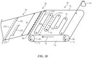
- FIG. 10 is a perspective view of illustrative equipment that may be used to insert weft strands 12-2 into fabric 20 during knitting.
- weft strand insertion equipment 26 may include a conveyor belt structure such as conveyor 74 having a number of structures 70 (e.g., hooks, pins, posts, etc.) around which weft strands 12-2 are wrapped. Hooks 70 hold each weft strand segment 12S parallel to the width W of fabric 20.
- rollers 80 rotate in direction 72 which in turn moves conveyor surface 76 in direction 78.
- Weft segments 12S are released from conveyor 74 and placed cross-wise into fabric 20 (see, e.g., FIG. 9 ).
- the width of weft strand segments 12S is determined by the spacing between posts 70.
- equipment 26 may have a uniform spacing between posts 70 to form weft segments of uniform width, or equipment 26 may have variable spacing between posts 70 to form weft segments with variable width, as shown in FIG. 10 .
- a distance D1 may separate one pair of opposing posts 70, while a distance D2 (e.g., a distance less than D1) may separate another pair of opposing posts.
- the positions of posts 70 on conveyor surface 76 may be fixed or the positions may be adjustable. In either case, the weft insertion strand 12-2 may be pre-loaded onto conveyor surface 76 in a particular pattern.
- the pattern in which weft strand 12-2 is placed on conveyor surface 76 may correspond to the pattern to be created in fabric 20 with weft strand 12-2.
- the distances D1 and D2 between neighboring pairs of posts 70 on conveyor surface 76 may create first and second weft insertion segments 12S in fabric 20 having widths D1 and D2.
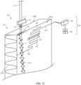
- weft insertion equipment 26 includes a conveyor system on which the pattern of weft insertion strands 12-2 is pre-loaded prior to inserting the weft strands 12-2 in fabric 20 is merely illustrative. If desired, weft insertion equipment 26 may include computer-controlled weft strand positioning equipment that precisely moves and positions weft strands in fabric 20. This type of arrangement is shown in FIG. 11 .
- fabric 20 is a multi-layer fabric having a spacer layer 82S interposed between first and second outer layers 82A and 82B.
- Multi-layer fabrics of this type may, for example, be formed using Raschel double-needle bar machine in which threaded guide bars form outer layers 82A and 82B and an additional threaded guide bar is used to attach outer layer 82A and 82B with spacer layer 82S.
- the spacer construction of FIG. 11 may be used to form a touch-sensitive textile.
- Each outer layer 82A and 82B may include a set of conductive strands.
- the spacer layer may compress or deform in response to a touch on the textile, which, in some cases, causes the distance between conductive strands in layer 82A to come closer to the conductive strands in layer 82B.
- the change in distance between the conductive strands may cause a change in capacitance between the conductive strands, which may be monitored by a sensing circuit. If desired, a force associated with the touch may be determined based on the change in capacitance.
- weft strand positioning equipment 26 may include a feeder 84 (sometimes referred to as a carrier, a weft insertion device, or weft strand positioner) that feeds weft strands 12-2 into fabric 20 during weaving.
- the location at which weft strands 12-2 are inserted into fabric 20 may be similar to that of FIGS. 9 and 10 (e.g., between previously formed loops and newly wrapped strands to be looped with previously formed loops).
- equipment 26 of FIG. 11 produces the pattern of weft strands 12-2 as the weft strands are inserted into fabric 20.
- feeder 84 may move across knitting machine 28 along direction 108 while feeding weft strand 12-2 into fabric 20 as knitting machine 28 knits fabric 20.
- Feeder 84 may be controlled by computer-controlled positioner 86. If desired, computer-controlled positioner 86 may synchronize the movement and placement of feeder 84 with the operation of knitting machine 28 such that the pattern of weft insertion strands 12-2 can be customized and adjusted during knitting without requiring any change in operation of knitting machine 28.
- Computer-controlled positioner 86 manipulates feeder 84 to insert segments 12S of weft strands 12-2 in fabric 20. As shown in FIG. 11 , weft segments 12S may have different widths and may span different portions of fabric 20. The width 110 of a given segment 12S in fabric 20 may be determined by the movement of weft insertion equipment 26. For example, to produce a segment of width 110 in fabric 20, computer-controlled positioner 86 may move insertion device 84 across width 110 while placing weft segment 12S into knitting machine 28. The weft segment is integrated into fabric 20 as knitting machine 28 forms loops with warp strands 12-1.
- weft strand positioning equipment 26 may include multiple feeders 84.
- one feeder 84 may feed weft strands 12-2 to layer 82A while another feeder 84 feeds weft strands 12-2 to layer 82B.
- weft strands 12-2 of layer 82A and weft strands 12-2 of layer 82B may be conductive and may overlap one another. The overlapping regions of conductive weft strands may, for example, form sensor electrodes as part of a touch sensor and/or force sensor in fabric 20.
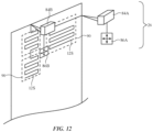
- feeders 84 may be used for any one or more of layers 82A, 82B, and 82C. This type of arrangement is shown in FIG. 12 .
- weft insertion equipment 26 may include multiple feeders such as feeder 84A controlled by positioner 86A and feeder 84B controlled by positioner 86B.
- Feeders 84A and 84B may operate independently of one another to create multiple regions 90 of weft segments 12S in fabric 20. Because regions 90 of weft segments 12S are created independently of one another, each region 90 may have a different pattern of weft segments. The widths of segments 12S within a given region 90 may be fixed or may be variable.
- FIG. 12 The example of FIG. 12 in which two feeders 84 are used to independently insert different weft strands 12-2 in fabric 20 is merely illustrative. If desired, one, two, three, four, or more than four feeders 84 may be used to insert and control the width of weft segments 12S in fabric 20.
- the ability to insert weft segments 12S with variable widths and patterns allows for the creation of regions 90 having different shapes, sizes, and functions in fabric 20. Regions 90 may create an aesthetically pleasing design in fabric 20 and/or may be used for functional purposes (e.g., to create different patterns, shapes, and sizes of touch-sensitive and/or force-sensitive regions in fabric 20).
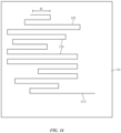
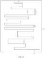
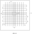
- FIGS. 13 , 14 , 15 , and 16 show various patterns that can be made with a weft insertion strand using the equipment and methods described in FIGS. 4-12 .
- weft strand 12-2 forms a number of parallel weft segments 12S in fabric 20.
- Weft segments 12S may have different widths W.
- weft segments 12S in region 92 may have a greater width than weft segments 12S in region 94.
- the spacing S between adjacent segments 12S is uniform in fabric 20.
- segments 12S may have a non-uniform spacing.
- weft strand 12-2 has segments of variable width and has different patterns in different regions of fabric 20.
- weft strand 12-2 has segments 12S with variable width and a variable spacing S between neighboring segments. For example, one pair of segments 12S may have be spaced apart by a distance S1, whereas another pair of segments 12S may be spaced apart by a distance S2 that is less than S1.
- fabric 20 includes both weft insertion strands 12-2 and warp insertion strands 12-3.
- the spacing between weft strands 12-2 and the spacing between warp strands 12-3 may be adjusted to create regions of different resolutions.
- warp strands 12-3 in region 96 may be spaced closer together than warp strands 12-3 in other regions of fabric 20.
- Weft strands 12-2 in region 98 may be spaced closer together than weft strands 12-2 in other regions of fabric 20.
- region 100 may create a discrete touch-sensitive and/or force-sensitive region in fabric 20.
Landscapes
- Engineering & Computer Science (AREA)
- Textile Engineering (AREA)
- Knitting Of Fabric (AREA)
Claims (8)
- Kettwirkware (20), umfassend:eine Vielzahl von Kettfäden (12-1), die miteinander verschlungen sind, wobei die Kettfäden (12-1) einen ersten Kettfaden, der eine erste Kante des Gewebes (20) bildet, und einen zweiten Kettfaden, der eine zweite Kante des Gewebes (20) bildet, umfassen und wobei sich eine Breite (W) der Kettwirkware (20) von der ersten Kante zur zweiten Kante erstreckt;einen Schusseinziehfaden (12-2, 12-2', 12-2"), der in die Kettwirkware (20) quer zu den Kettfäden (12-1) zwischen dem ersten und dem zweiten Rand des Gewirkes (20) eingetragen ist, wobei sich der Schusseinziehfaden (12-2, 12-2', 12-2") über weniger als alle Kettfäden (12-1) erstreckt, wobei der Schusseinziehfaden (12-2, 12-2', 12-2") einen leitenden Faden umfasst, der elektrische Signale überträgt, und gekennzeichnet durcheinen Ketteinziehfaden (12-3), die in die Kettwirkware (20) entlang der Länge (L) der Kettwirkware (20) eingefügt ist.
- Kettwirkware (20) nach Anspruch 1, wobei der Schusseinziehfaden (12-2, 12-2', 12-2") eine Vielzahl von parallelen Schussfaden-Segmenten (12S) aufweist und wobei sich jedes Schussfaden-Segment (12S) über mindestens einige der Kettfäden (12-1) erstreckt.
- Kettwirkware (20) nach Anspruch 2, wobei die Schussfaden-Segmente (12S) mindestens ein erstes Schussfaden-Segment, das sich über einen ersten Satz von Kettfäden in der Vielzahl von Kettfäden (12-1) erstreckt, und ein zweites Schussfaden-Segment, das sich über einen zweiten Satz von Kettfäden in der Vielzahl von Kettfäden (12-1) erstreckt, der sich von dem ersten Satz von Kettfäden unterscheidet, umfassen.
- Kettwirkware (20) nach Anspruch 2, wobei der Abstand zwischen den Schussfaden-Segmenten gleichmäßig ist.
- Kettwirkware (20) nach Anspruch 2, bei der der Abstand zwischen den Schussfaden-Segmenten des Schussfadens ungleichmäßig ist.
- Kettwirkware (20) nach Anspruch 1, ferner umfassend: einen zusätzlichen Schusseinziehfaden (12-2, 12-2', 12-2"), der quer zu den Kettfäden (12-1) zwischen dem ersten und dem zweiten Rand der Ware (20) eingetragen ist, wobei sich der zusätzliche Schussfaden (12-2, 12-2', 12-2") über weniger als alle Kettfäden (12-1) erstreckt.
- Kettwirkware (20) nach Anspruch 6, wobei der Schusseinziehfaden (12-2, 12-2', 12-2") einem ersten Muster in der Kettwirkware (20) folgt, wobei der zusätzliche Schusseinziehfaden (12-2, 12-2', 12-2") einem zweiten Muster in der Kettwirkware (20) folgt, und wobei das erste Muster sich von dem zweiten Muster unterscheidet.
- Kettenwirkware (20) nach Anspruch 6, wobei sich der Schusseinziehfaden (12-2, 12-2', 12-2") über einen ersten Satz von Kettfäden in der Vielzahl von Kettfäden (12-1) erstreckt, wobei sich der zusätzliche Schusseinziehfaden (12-2, 12-2', 12-2") über einen zweiten Satz von Kettfäden in der Vielzahl von Kettfäden (12-1) erstreckt, und wobei der erste Satz von Kettfäden anders ist als der zweite Satz von Kettfäden.
Applications Claiming Priority (2)
| Application Number | Priority Date | Filing Date | Title |
|---|---|---|---|
| US201562186285P | 2015-06-29 | 2015-06-29 | |
| PCT/US2016/038678 WO2017003783A1 (en) | 2015-06-29 | 2016-06-22 | Warp knit fabrics with variable path weft strands |
Publications (2)
| Publication Number | Publication Date |
|---|---|
| EP3314048A1 EP3314048A1 (de) | 2018-05-02 |
| EP3314048B1 true EP3314048B1 (de) | 2025-02-19 |
Family
ID=56409684
Family Applications (1)
| Application Number | Title | Priority Date | Filing Date |
|---|---|---|---|
| EP16738585.5A Active EP3314048B1 (de) | 2015-06-29 | 2016-06-22 | Kettengewirk mit schussfäden mit variablem weg |
Country Status (4)
| Country | Link |
|---|---|
| US (1) | US10829878B2 (de) |
| EP (1) | EP3314048B1 (de) |
| JP (1) | JP6676665B2 (de) |
| WO (1) | WO2017003783A1 (de) |
Families Citing this family (15)
| Publication number | Priority date | Publication date | Assignee | Title |
|---|---|---|---|---|
| US10526731B2 (en) * | 2014-12-22 | 2020-01-07 | Apple, Inc. | Conductive signal paths in woven fabrics |
| US10577732B1 (en) * | 2016-02-26 | 2020-03-03 | Apple Inc. | Knit fabric with electrical components |
| JP6146509B1 (ja) * | 2016-03-31 | 2017-06-14 | タカタ株式会社 | 乗員拘束ベルト用ウェビング、シートベルト、及びシートベルト装置 |
| US10145036B1 (en) * | 2016-05-04 | 2018-12-04 | Apple Inc. | Items with conductive yarn |
| US10180721B2 (en) * | 2017-06-14 | 2019-01-15 | Apple Inc. | Fabric-based devices with force sensing |
| US10156029B1 (en) | 2017-06-14 | 2018-12-18 | Apple Inc. | Fabric control device |
| US11986064B2 (en) * | 2018-05-17 | 2024-05-21 | Kuraray Fastening Co., Ltd. | Conductive surface fastener and production method therefor |
| WO2020038552A1 (de) * | 2018-08-20 | 2020-02-27 | Relytex Gmbh + Co. Kg I.G. | Verfahren zur herstellung einer sende- und/oder empfangsantenne auf einem textilen trägermaterial |
| WO2020081557A1 (en) * | 2018-10-15 | 2020-04-23 | Drexel University | Knitted capacitive touch sensor and capacitive touch sensor (active) textile |
| CN109505054A (zh) * | 2018-12-27 | 2019-03-22 | 东莞超盈纺织有限公司 | 一种非热熔材质的任意裁蕾丝花边织物 |
| WO2020210644A1 (en) | 2019-04-10 | 2020-10-15 | Propel, LLC | Knitted textiles with conductive traces of a hybrid yarn and methods of knitting the same |
| US12003916B1 (en) * | 2020-03-30 | 2024-06-04 | Apple Inc. | Electronic devices with sound permeable fabric |
| US20230008099A1 (en) * | 2021-07-12 | 2023-01-12 | Apple Inc. | Fabric Seam with Electrical Components |
| DE102022004262A1 (de) * | 2022-11-18 | 2024-05-23 | Gottlieb Binder Gmbh & Co. Kg | Sensorvorrichtung |
| US20240417895A1 (en) * | 2023-06-13 | 2024-12-19 | Apple Inc. | Fabric with Electrical Components |
Citations (4)
| Publication number | Priority date | Publication date | Assignee | Title |
|---|---|---|---|---|
| US3084529A (en) * | 1958-02-06 | 1963-04-09 | Scheibe Walter Hugo | Open mesh warp knitted fabric |
| DE3800320A1 (de) * | 1986-12-31 | 1989-07-20 | Textima Veb K | Steuersystem fuer schussfaeden (schussfadenhalteleiste) |
| DE102008034937A1 (de) * | 2008-07-26 | 2010-02-04 | Müller Textil GmbH | Abstandsgewirke und Verfahren zu dessen Herstellung |
| EP2743387A1 (de) * | 2012-12-14 | 2014-06-18 | Fundacio Cetemmsa | Stoffprodukt und daraus hergestellter Sensorstoff |
Family Cites Families (21)
| Publication number | Priority date | Publication date | Assignee | Title |
|---|---|---|---|---|
| US3733859A (en) * | 1970-09-04 | 1973-05-22 | Darlington Fabrics Corp | Warp knit elastic fabric |
| JPS6127085A (ja) * | 1984-07-14 | 1986-02-06 | 旭化成株式会社 | 導電性布帛材料 |
| DE3634162A1 (de) * | 1986-10-07 | 1988-04-21 | Ries Gmbh Bekleidungsverschlus | Reissverschluss und verfahren zu dessen herstellung |
| US5290619A (en) * | 1991-07-05 | 1994-03-01 | Ct-Nassau Corporation | Knitted mattress tape |
| FR2695003B1 (fr) * | 1992-08-31 | 1994-10-28 | Catherine Bellon | Clôture électrique à réseau conducteur perfectionné. |
| US5265445A (en) * | 1992-09-01 | 1993-11-30 | Shytles Douglas M | Breathable elastic fabric and method of making same |
| US5585169A (en) * | 1995-01-20 | 1996-12-17 | Burlington Industries, Inc. | Warp-knit, weft-inserted fabric construction with dyed substrate |
| US5502986A (en) * | 1995-06-21 | 1996-04-02 | Ykk Corporation | Knit slide fastener |
| US5809805A (en) * | 1996-09-03 | 1998-09-22 | Mcdonnell Douglas Corporation | Warp/knit reinforced structural fabric |
| US5797283A (en) * | 1997-05-14 | 1998-08-25 | Novtex Corp. | Crochet knitted decorative ribbon with severable sections forming decorative curls |
| DE29901225U1 (de) * | 1998-01-26 | 1999-05-12 | Müller, Peter, 83209 Prien | Abstandsgewirke zur Aufpolsterung |
| US6276177B1 (en) * | 1999-09-03 | 2001-08-21 | Liberty Fabrics | Knitted elastomeric fabric |
| WO2002050352A1 (en) * | 2000-12-18 | 2002-06-27 | Asahi Doken Kabushiki Kaisha | Double knitted fabric |
| WO2002044452A2 (en) * | 2000-11-30 | 2002-06-06 | Alnet (Proprietary) Limited | A knitted fabric |
| CN100551291C (zh) * | 2003-06-02 | 2009-10-21 | Ykk株式会社 | 针织、机织的隐形拉链 |
| JP4457141B2 (ja) * | 2007-10-04 | 2010-04-28 | 株式会社タケダレース | 部分低伸長伸縮性経編地 |
| KR101325817B1 (ko) * | 2010-01-14 | 2013-11-05 | 실버레이 주식회사 | 도전성 직조물, 그 제조방법 및 제조장치 |
| JP2012136813A (ja) * | 2010-12-09 | 2012-07-19 | Yoshida Sangyo Kk | 伸縮パワー強化部ないし非伸縮性付与部からなる補強部を有する経編衣料 |
| WO2014159807A1 (en) * | 2013-03-13 | 2014-10-02 | Federal-Mogul Powertrain, Inc. | Warp knit wrappable sleeve with extendable electro-functional yarns and method of construction thereof |
| DE102013018883B4 (de) * | 2013-11-12 | 2015-10-15 | Freundes- Und Förderkreis Des Instituts Fuer Textiltechnik Der Rwth Aachen University | Verfahren zur Herstellung eines Textils und Textil zur Energiewandlung |
| JP6271959B2 (ja) * | 2013-11-14 | 2018-01-31 | 竹中繊維株式会社 | 繊維電極付き生地、繊維電極付き生地の製造方法及び電気インピーダンス測定用ベルト |
-
2016
- 2016-06-22 EP EP16738585.5A patent/EP3314048B1/de active Active
- 2016-06-22 JP JP2017567358A patent/JP6676665B2/ja active Active
- 2016-06-22 WO PCT/US2016/038678 patent/WO2017003783A1/en not_active Ceased
-
2018
- 2018-03-06 US US15/913,653 patent/US10829878B2/en active Active
Patent Citations (4)
| Publication number | Priority date | Publication date | Assignee | Title |
|---|---|---|---|---|
| US3084529A (en) * | 1958-02-06 | 1963-04-09 | Scheibe Walter Hugo | Open mesh warp knitted fabric |
| DE3800320A1 (de) * | 1986-12-31 | 1989-07-20 | Textima Veb K | Steuersystem fuer schussfaeden (schussfadenhalteleiste) |
| DE102008034937A1 (de) * | 2008-07-26 | 2010-02-04 | Müller Textil GmbH | Abstandsgewirke und Verfahren zu dessen Herstellung |
| EP2743387A1 (de) * | 2012-12-14 | 2014-06-18 | Fundacio Cetemmsa | Stoffprodukt und daraus hergestellter Sensorstoff |
Also Published As
| Publication number | Publication date |
|---|---|
| WO2017003783A1 (en) | 2017-01-05 |
| EP3314048A1 (de) | 2018-05-02 |
| US10829878B2 (en) | 2020-11-10 |
| US20180195218A1 (en) | 2018-07-12 |
| JP6676665B2 (ja) | 2020-04-08 |
| JP2018518607A (ja) | 2018-07-12 |
Similar Documents
| Publication | Publication Date | Title |
|---|---|---|
| EP3314048B1 (de) | Kettengewirk mit schussfäden mit variablem weg | |
| CN111534899B (zh) | 织造织物中的导电信号路径 | |
| US10385487B2 (en) | Electrically conductive fabric and manufacturing method and apparatus thereof | |
| EP2743386B1 (de) | Leitfähiges Textil sowie Verfahren zu seiner Herstellung | |
| EP3256627B1 (de) | Gewebe mit leiterbahnen | |
| EP3705612B1 (de) | Gewebe mit elektrischen komponenten | |
| EP3575462B1 (de) | Strickmaschine und verfahren zum stricken eines textilartikels auf einer flachstrickmaschine | |
| US20210355613A1 (en) | Knitted capacitive touch sensor and capacitive touch sensor (active) textile | |
| US10323344B2 (en) | Method for manufacturing a knitted fabric comprising a vertical yarn filament | |
| US10900154B2 (en) | Knit fabric with electrical components | |
| US20240417898A1 (en) | Warp Knit and Braided Fabrics with Electrical Components | |
| US20240417895A1 (en) | Fabric with Electrical Components | |
| EP4305228A1 (de) | Stoffartikel und verfahren zur herstellung davon | |
| US20230078969A1 (en) | Tubular Warp Knit Spacer Fabric | |
| EP3239376B1 (de) | Verfahren zum stricken eines doppelseitigen gewebes, eingebettet mit kontinuierlichem linearem material und als gebogene form ausgebildet | |
| US20240417897A1 (en) | Weft Knit Fabric with Electrical Components | |
| US20250011981A1 (en) | Fabric with Circuitry and Electrical Components | |
| WO2025014738A1 (en) | Fabric with circuitry and electrical components |
Legal Events
| Date | Code | Title | Description |
|---|---|---|---|
| STAA | Information on the status of an ep patent application or granted ep patent |
Free format text: STATUS: THE INTERNATIONAL PUBLICATION HAS BEEN MADE |
|
| PUAI | Public reference made under article 153(3) epc to a published international application that has entered the european phase |
Free format text: ORIGINAL CODE: 0009012 |
|
| STAA | Information on the status of an ep patent application or granted ep patent |
Free format text: STATUS: REQUEST FOR EXAMINATION WAS MADE |
|
| 17P | Request for examination filed |
Effective date: 20171227 |
|
| AK | Designated contracting states |
Kind code of ref document: A1 Designated state(s): AL AT BE BG CH CY CZ DE DK EE ES FI FR GB GR HR HU IE IS IT LI LT LU LV MC MK MT NL NO PL PT RO RS SE SI SK SM TR |
|
| AX | Request for extension of the european patent |
Extension state: BA ME |
|
| RAP1 | Party data changed (applicant data changed or rights of an application transferred) |
Owner name: APPLE INC. |
|
| DAV | Request for validation of the european patent (deleted) | ||
| DAX | Request for extension of the european patent (deleted) | ||
| STAA | Information on the status of an ep patent application or granted ep patent |
Free format text: STATUS: EXAMINATION IS IN PROGRESS |
|
| 17Q | First examination report despatched |
Effective date: 20210430 |
|
| GRAP | Despatch of communication of intention to grant a patent |
Free format text: ORIGINAL CODE: EPIDOSNIGR1 |
|
| STAA | Information on the status of an ep patent application or granted ep patent |
Free format text: STATUS: GRANT OF PATENT IS INTENDED |
|
| RIC1 | Information provided on ipc code assigned before grant |
Ipc: D04B 27/32 20060101ALI20240925BHEP Ipc: D04B 23/22 20060101ALI20240925BHEP Ipc: D04B 21/14 20060101AFI20240925BHEP |
|
| INTG | Intention to grant announced |
Effective date: 20241008 |
|
| GRAS | Grant fee paid |
Free format text: ORIGINAL CODE: EPIDOSNIGR3 |
|
| GRAA | (expected) grant |
Free format text: ORIGINAL CODE: 0009210 |
|
| STAA | Information on the status of an ep patent application or granted ep patent |
Free format text: STATUS: THE PATENT HAS BEEN GRANTED |
|
| AK | Designated contracting states |
Kind code of ref document: B1 Designated state(s): AL AT BE BG CH CY CZ DE DK EE ES FI FR GB GR HR HU IE IS IT LI LT LU LV MC MK MT NL NO PL PT RO RS SE SI SK SM TR |
|
| REG | Reference to a national code |
Ref country code: GB Ref legal event code: FG4D |
|
| REG | Reference to a national code |
Ref country code: CH Ref legal event code: EP |
|
| REG | Reference to a national code |
Ref country code: DE Ref legal event code: R096 Ref document number: 602016091272 Country of ref document: DE |
|
| REG | Reference to a national code |
Ref country code: IE Ref legal event code: FG4D |
|
| P01 | Opt-out of the competence of the unified patent court (upc) registered |
Free format text: CASE NUMBER: APP_11256/2025 Effective date: 20250307 |
|
| REG | Reference to a national code |
Ref country code: NL Ref legal event code: MP Effective date: 20250219 |
|
| PG25 | Lapsed in a contracting state [announced via postgrant information from national office to epo] |
Ref country code: RS Free format text: LAPSE BECAUSE OF FAILURE TO SUBMIT A TRANSLATION OF THE DESCRIPTION OR TO PAY THE FEE WITHIN THE PRESCRIBED TIME-LIMIT Effective date: 20250519 |
|
| PG25 | Lapsed in a contracting state [announced via postgrant information from national office to epo] |
Ref country code: FI Free format text: LAPSE BECAUSE OF FAILURE TO SUBMIT A TRANSLATION OF THE DESCRIPTION OR TO PAY THE FEE WITHIN THE PRESCRIBED TIME-LIMIT Effective date: 20250219 |
|
| PG25 | Lapsed in a contracting state [announced via postgrant information from national office to epo] |
Ref country code: PL Free format text: LAPSE BECAUSE OF FAILURE TO SUBMIT A TRANSLATION OF THE DESCRIPTION OR TO PAY THE FEE WITHIN THE PRESCRIBED TIME-LIMIT Effective date: 20250219 |
|
| PGFP | Annual fee paid to national office [announced via postgrant information from national office to epo] |
Ref country code: DE Payment date: 20250319 Year of fee payment: 10 |
|
| PG25 | Lapsed in a contracting state [announced via postgrant information from national office to epo] |
Ref country code: ES Free format text: LAPSE BECAUSE OF FAILURE TO SUBMIT A TRANSLATION OF THE DESCRIPTION OR TO PAY THE FEE WITHIN THE PRESCRIBED TIME-LIMIT Effective date: 20250219 |
|
| REG | Reference to a national code |
Ref country code: LT Ref legal event code: MG9D |
|
| PG25 | Lapsed in a contracting state [announced via postgrant information from national office to epo] |
Ref country code: IS Free format text: LAPSE BECAUSE OF FAILURE TO SUBMIT A TRANSLATION OF THE DESCRIPTION OR TO PAY THE FEE WITHIN THE PRESCRIBED TIME-LIMIT Effective date: 20250619 Ref country code: NO Free format text: LAPSE BECAUSE OF FAILURE TO SUBMIT A TRANSLATION OF THE DESCRIPTION OR TO PAY THE FEE WITHIN THE PRESCRIBED TIME-LIMIT Effective date: 20250519 |
|
| PG25 | Lapsed in a contracting state [announced via postgrant information from national office to epo] |
Ref country code: NL Free format text: LAPSE BECAUSE OF FAILURE TO SUBMIT A TRANSLATION OF THE DESCRIPTION OR TO PAY THE FEE WITHIN THE PRESCRIBED TIME-LIMIT Effective date: 20250219 |
|
| PG25 | Lapsed in a contracting state [announced via postgrant information from national office to epo] |
Ref country code: HR Free format text: LAPSE BECAUSE OF FAILURE TO SUBMIT A TRANSLATION OF THE DESCRIPTION OR TO PAY THE FEE WITHIN THE PRESCRIBED TIME-LIMIT Effective date: 20250219 |
|
| PG25 | Lapsed in a contracting state [announced via postgrant information from national office to epo] |
Ref country code: PT Free format text: LAPSE BECAUSE OF FAILURE TO SUBMIT A TRANSLATION OF THE DESCRIPTION OR TO PAY THE FEE WITHIN THE PRESCRIBED TIME-LIMIT Effective date: 20250620 Ref country code: LV Free format text: LAPSE BECAUSE OF FAILURE TO SUBMIT A TRANSLATION OF THE DESCRIPTION OR TO PAY THE FEE WITHIN THE PRESCRIBED TIME-LIMIT Effective date: 20250219 |
|
| PG25 | Lapsed in a contracting state [announced via postgrant information from national office to epo] |
Ref country code: GR Free format text: LAPSE BECAUSE OF FAILURE TO SUBMIT A TRANSLATION OF THE DESCRIPTION OR TO PAY THE FEE WITHIN THE PRESCRIBED TIME-LIMIT Effective date: 20250520 Ref country code: BG Free format text: LAPSE BECAUSE OF FAILURE TO SUBMIT A TRANSLATION OF THE DESCRIPTION OR TO PAY THE FEE WITHIN THE PRESCRIBED TIME-LIMIT Effective date: 20250219 |
|
| REG | Reference to a national code |
Ref country code: AT Ref legal event code: MK05 Ref document number: 1768358 Country of ref document: AT Kind code of ref document: T Effective date: 20250219 |
|
| PG25 | Lapsed in a contracting state [announced via postgrant information from national office to epo] |
Ref country code: SE Free format text: LAPSE BECAUSE OF FAILURE TO SUBMIT A TRANSLATION OF THE DESCRIPTION OR TO PAY THE FEE WITHIN THE PRESCRIBED TIME-LIMIT Effective date: 20250219 |
|
| PG25 | Lapsed in a contracting state [announced via postgrant information from national office to epo] |
Ref country code: SM Free format text: LAPSE BECAUSE OF FAILURE TO SUBMIT A TRANSLATION OF THE DESCRIPTION OR TO PAY THE FEE WITHIN THE PRESCRIBED TIME-LIMIT Effective date: 20250219 |
|
| PG25 | Lapsed in a contracting state [announced via postgrant information from national office to epo] |
Ref country code: DK Free format text: LAPSE BECAUSE OF FAILURE TO SUBMIT A TRANSLATION OF THE DESCRIPTION OR TO PAY THE FEE WITHIN THE PRESCRIBED TIME-LIMIT Effective date: 20250219 |
|
| PG25 | Lapsed in a contracting state [announced via postgrant information from national office to epo] |
Ref country code: IT Free format text: LAPSE BECAUSE OF FAILURE TO SUBMIT A TRANSLATION OF THE DESCRIPTION OR TO PAY THE FEE WITHIN THE PRESCRIBED TIME-LIMIT Effective date: 20250219 |
|
| PG25 | Lapsed in a contracting state [announced via postgrant information from national office to epo] |
Ref country code: AT Free format text: LAPSE BECAUSE OF FAILURE TO SUBMIT A TRANSLATION OF THE DESCRIPTION OR TO PAY THE FEE WITHIN THE PRESCRIBED TIME-LIMIT Effective date: 20250219 |
|
| PG25 | Lapsed in a contracting state [announced via postgrant information from national office to epo] |
Ref country code: CZ Free format text: LAPSE BECAUSE OF FAILURE TO SUBMIT A TRANSLATION OF THE DESCRIPTION OR TO PAY THE FEE WITHIN THE PRESCRIBED TIME-LIMIT Effective date: 20250219 Ref country code: EE Free format text: LAPSE BECAUSE OF FAILURE TO SUBMIT A TRANSLATION OF THE DESCRIPTION OR TO PAY THE FEE WITHIN THE PRESCRIBED TIME-LIMIT Effective date: 20250219 |
|
| PG25 | Lapsed in a contracting state [announced via postgrant information from national office to epo] |
Ref country code: RO Free format text: LAPSE BECAUSE OF FAILURE TO SUBMIT A TRANSLATION OF THE DESCRIPTION OR TO PAY THE FEE WITHIN THE PRESCRIBED TIME-LIMIT Effective date: 20250219 |
|
| PG25 | Lapsed in a contracting state [announced via postgrant information from national office to epo] |
Ref country code: SK Free format text: LAPSE BECAUSE OF FAILURE TO SUBMIT A TRANSLATION OF THE DESCRIPTION OR TO PAY THE FEE WITHIN THE PRESCRIBED TIME-LIMIT Effective date: 20250219 |
|
| REG | Reference to a national code |
Ref country code: DE Ref legal event code: R097 Ref document number: 602016091272 Country of ref document: DE |
|
| PLBE | No opposition filed within time limit |
Free format text: ORIGINAL CODE: 0009261 |
|
| STAA | Information on the status of an ep patent application or granted ep patent |
Free format text: STATUS: NO OPPOSITION FILED WITHIN TIME LIMIT |
|
| REG | Reference to a national code |
Ref country code: CH Ref legal event code: L10 Free format text: ST27 STATUS EVENT CODE: U-0-0-L10-L00 (AS PROVIDED BY THE NATIONAL OFFICE) Effective date: 20251231 |
|
| REG | Reference to a national code |
Ref country code: CH Ref legal event code: H13 Free format text: ST27 STATUS EVENT CODE: U-0-0-H10-H13 (AS PROVIDED BY THE NATIONAL OFFICE) Effective date: 20260127 |
|
| 26N | No opposition filed |
Effective date: 20251120 |
|
| PG25 | Lapsed in a contracting state [announced via postgrant information from national office to epo] |
Ref country code: MC Free format text: LAPSE BECAUSE OF FAILURE TO SUBMIT A TRANSLATION OF THE DESCRIPTION OR TO PAY THE FEE WITHIN THE PRESCRIBED TIME-LIMIT Effective date: 20250219 |
|
| PG25 | Lapsed in a contracting state [announced via postgrant information from national office to epo] |
Ref country code: LU Free format text: LAPSE BECAUSE OF NON-PAYMENT OF DUE FEES Effective date: 20250622 |
|
| GBPC | Gb: european patent ceased through non-payment of renewal fee |
Effective date: 20250622 |
|
| REG | Reference to a national code |
Ref country code: BE Ref legal event code: MM Effective date: 20250630 |
|
| PG25 | Lapsed in a contracting state [announced via postgrant information from national office to epo] |
Ref country code: GB Free format text: LAPSE BECAUSE OF NON-PAYMENT OF DUE FEES Effective date: 20250622 |
|
| PG25 | Lapsed in a contracting state [announced via postgrant information from national office to epo] |
Ref country code: IE Free format text: LAPSE BECAUSE OF NON-PAYMENT OF DUE FEES Effective date: 20250622 |
|
| PG25 | Lapsed in a contracting state [announced via postgrant information from national office to epo] |
Ref country code: BE Free format text: LAPSE BECAUSE OF NON-PAYMENT OF DUE FEES Effective date: 20250630 |
|
| PG25 | Lapsed in a contracting state [announced via postgrant information from national office to epo] |
Ref country code: FR Free format text: LAPSE BECAUSE OF NON-PAYMENT OF DUE FEES Effective date: 20250630 |
|
| PG25 | Lapsed in a contracting state [announced via postgrant information from national office to epo] |
Ref country code: CH Free format text: LAPSE BECAUSE OF NON-PAYMENT OF DUE FEES Effective date: 20250630 |