EP3313498B1 - System zur verfolgung und bestimmung der eigenschaften von aufblasbaren medizinischen instrumenten anhand von faseroptischen realshape-daten - Google Patents
System zur verfolgung und bestimmung der eigenschaften von aufblasbaren medizinischen instrumenten anhand von faseroptischen realshape-daten Download PDFInfo
- Publication number
- EP3313498B1 EP3313498B1 EP16730298.3A EP16730298A EP3313498B1 EP 3313498 B1 EP3313498 B1 EP 3313498B1 EP 16730298 A EP16730298 A EP 16730298A EP 3313498 B1 EP3313498 B1 EP 3313498B1
- Authority
- EP
- European Patent Office
- Prior art keywords
- medical instrument
- inflatable medical
- shape
- fors
- analysis module
- Prior art date
- Legal status (The legal status is an assumption and is not a legal conclusion. Google has not performed a legal analysis and makes no representation as to the accuracy of the status listed.)
- Active
Links
Images


Classifications
-
- A—HUMAN NECESSITIES
- A61—MEDICAL OR VETERINARY SCIENCE; HYGIENE
- A61B—DIAGNOSIS; SURGERY; IDENTIFICATION
- A61B5/00—Measuring for diagnostic purposes; Identification of persons
- A61B5/68—Arrangements of detecting, measuring or recording means, e.g. sensors, in relation to patient
- A61B5/6846—Arrangements of detecting, measuring or recording means, e.g. sensors, in relation to patient specially adapted to be brought in contact with an internal body part, i.e. invasive
- A61B5/6847—Arrangements of detecting, measuring or recording means, e.g. sensors, in relation to patient specially adapted to be brought in contact with an internal body part, i.e. invasive mounted on an invasive device
- A61B5/6852—Catheters
- A61B5/6853—Catheters with a balloon
-
- A—HUMAN NECESSITIES
- A61—MEDICAL OR VETERINARY SCIENCE; HYGIENE
- A61B—DIAGNOSIS; SURGERY; IDENTIFICATION
- A61B34/00—Computer-aided surgery; Manipulators or robots specially adapted for use in surgery
- A61B34/20—Surgical navigation systems; Devices for tracking or guiding surgical instruments, e.g. for frameless stereotaxis
-
- A—HUMAN NECESSITIES
- A61—MEDICAL OR VETERINARY SCIENCE; HYGIENE
- A61B—DIAGNOSIS; SURGERY; IDENTIFICATION
- A61B5/00—Measuring for diagnostic purposes; Identification of persons
- A61B5/103—Detecting, measuring or recording devices for testing the shape, pattern, colour, size or movement of the body or parts thereof, for diagnostic purposes
- A61B5/107—Measuring physical dimensions, e.g. size of the entire body or parts thereof
- A61B5/1076—Measuring physical dimensions, e.g. size of the entire body or parts thereof for measuring dimensions inside body cavities, e.g. using catheters
-
- A—HUMAN NECESSITIES
- A61—MEDICAL OR VETERINARY SCIENCE; HYGIENE
- A61B—DIAGNOSIS; SURGERY; IDENTIFICATION
- A61B90/00—Instruments, implements or accessories specially adapted for surgery or diagnosis and not covered by any of the groups A61B1/00 - A61B50/00, e.g. for luxation treatment or for protecting wound edges
- A61B90/36—Image-producing devices or illumination devices not otherwise provided for
- A61B90/37—Surgical systems with images on a monitor during operation
-
- A—HUMAN NECESSITIES
- A61—MEDICAL OR VETERINARY SCIENCE; HYGIENE
- A61M—DEVICES FOR INTRODUCING MEDIA INTO, OR ONTO, THE BODY; DEVICES FOR TRANSDUCING BODY MEDIA OR FOR TAKING MEDIA FROM THE BODY; DEVICES FOR PRODUCING OR ENDING SLEEP OR STUPOR
- A61M25/00—Catheters; Hollow probes
- A61M25/01—Introducing, guiding, advancing, emplacing or holding catheters
- A61M25/09—Guide wires
- A61M25/09041—Mechanisms for insertion of guide wires
-
- A—HUMAN NECESSITIES
- A61—MEDICAL OR VETERINARY SCIENCE; HYGIENE
- A61M—DEVICES FOR INTRODUCING MEDIA INTO, OR ONTO, THE BODY; DEVICES FOR TRANSDUCING BODY MEDIA OR FOR TAKING MEDIA FROM THE BODY; DEVICES FOR PRODUCING OR ENDING SLEEP OR STUPOR
- A61M25/00—Catheters; Hollow probes
- A61M25/10—Balloon catheters
- A61M25/1018—Balloon inflating or inflation-control devices
- A61M25/10184—Means for controlling or monitoring inflation or deflation
-
- A—HUMAN NECESSITIES
- A61—MEDICAL OR VETERINARY SCIENCE; HYGIENE
- A61M—DEVICES FOR INTRODUCING MEDIA INTO, OR ONTO, THE BODY; DEVICES FOR TRANSDUCING BODY MEDIA OR FOR TAKING MEDIA FROM THE BODY; DEVICES FOR PRODUCING OR ENDING SLEEP OR STUPOR
- A61M25/00—Catheters; Hollow probes
- A61M25/10—Balloon catheters
- A61M25/104—Balloon catheters used for angioplasty
-
- A—HUMAN NECESSITIES
- A61—MEDICAL OR VETERINARY SCIENCE; HYGIENE
- A61B—DIAGNOSIS; SURGERY; IDENTIFICATION
- A61B17/00—Surgical instruments, devices or methods, e.g. tourniquets
- A61B17/22—Implements for squeezing-off ulcers or the like on the inside of inner organs of the body; Implements for scraping-out cavities of body organs, e.g. bones; Calculus removers; Calculus smashing apparatus; Apparatus for removing obstructions in blood vessels, not otherwise provided for
- A61B2017/22038—Implements for squeezing-off ulcers or the like on the inside of inner organs of the body; Implements for scraping-out cavities of body organs, e.g. bones; Calculus removers; Calculus smashing apparatus; Apparatus for removing obstructions in blood vessels, not otherwise provided for with a guide wire
- A61B2017/22042—Details of the tip of the guide wire
-
- A—HUMAN NECESSITIES
- A61—MEDICAL OR VETERINARY SCIENCE; HYGIENE
- A61B—DIAGNOSIS; SURGERY; IDENTIFICATION
- A61B17/00—Surgical instruments, devices or methods, e.g. tourniquets
- A61B17/22—Implements for squeezing-off ulcers or the like on the inside of inner organs of the body; Implements for scraping-out cavities of body organs, e.g. bones; Calculus removers; Calculus smashing apparatus; Apparatus for removing obstructions in blood vessels, not otherwise provided for
- A61B2017/22051—Implements for squeezing-off ulcers or the like on the inside of inner organs of the body; Implements for scraping-out cavities of body organs, e.g. bones; Calculus removers; Calculus smashing apparatus; Apparatus for removing obstructions in blood vessels, not otherwise provided for with an inflatable part, e.g. balloon, for positioning, blocking, or immobilisation
-
- A—HUMAN NECESSITIES
- A61—MEDICAL OR VETERINARY SCIENCE; HYGIENE
- A61B—DIAGNOSIS; SURGERY; IDENTIFICATION
- A61B34/00—Computer-aided surgery; Manipulators or robots specially adapted for use in surgery
- A61B34/20—Surgical navigation systems; Devices for tracking or guiding surgical instruments, e.g. for frameless stereotaxis
- A61B2034/2046—Tracking techniques
- A61B2034/2061—Tracking techniques using shape-sensors, e.g. fiber shape sensors with Bragg gratings
-
- A—HUMAN NECESSITIES
- A61—MEDICAL OR VETERINARY SCIENCE; HYGIENE
- A61B—DIAGNOSIS; SURGERY; IDENTIFICATION
- A61B34/00—Computer-aided surgery; Manipulators or robots specially adapted for use in surgery
- A61B34/20—Surgical navigation systems; Devices for tracking or guiding surgical instruments, e.g. for frameless stereotaxis
- A61B2034/2046—Tracking techniques
- A61B2034/2065—Tracking using image or pattern recognition
-
- A—HUMAN NECESSITIES
- A61—MEDICAL OR VETERINARY SCIENCE; HYGIENE
- A61B—DIAGNOSIS; SURGERY; IDENTIFICATION
- A61B90/00—Instruments, implements or accessories specially adapted for surgery or diagnosis and not covered by any of the groups A61B1/00 - A61B50/00, e.g. for luxation treatment or for protecting wound edges
- A61B90/08—Accessories or related features not otherwise provided for
- A61B2090/0803—Counting the number of times an instrument is used
-
- A—HUMAN NECESSITIES
- A61—MEDICAL OR VETERINARY SCIENCE; HYGIENE
- A61B—DIAGNOSIS; SURGERY; IDENTIFICATION
- A61B90/00—Instruments, implements or accessories specially adapted for surgery or diagnosis and not covered by any of the groups A61B1/00 - A61B50/00, e.g. for luxation treatment or for protecting wound edges
- A61B90/08—Accessories or related features not otherwise provided for
- A61B2090/0807—Indication means
- A61B2090/0809—Indication of cracks or breakages
-
- A—HUMAN NECESSITIES
- A61—MEDICAL OR VETERINARY SCIENCE; HYGIENE
- A61B—DIAGNOSIS; SURGERY; IDENTIFICATION
- A61B90/00—Instruments, implements or accessories specially adapted for surgery or diagnosis and not covered by any of the groups A61B1/00 - A61B50/00, e.g. for luxation treatment or for protecting wound edges
- A61B90/36—Image-producing devices or illumination devices not otherwise provided for
- A61B90/361—Image-producing devices, e.g. surgical cameras
- A61B2090/3614—Image-producing devices, e.g. surgical cameras using optical fibre
-
- A—HUMAN NECESSITIES
- A61—MEDICAL OR VETERINARY SCIENCE; HYGIENE
- A61B—DIAGNOSIS; SURGERY; IDENTIFICATION
- A61B90/00—Instruments, implements or accessories specially adapted for surgery or diagnosis and not covered by any of the groups A61B1/00 - A61B50/00, e.g. for luxation treatment or for protecting wound edges
- A61B90/36—Image-producing devices or illumination devices not otherwise provided for
- A61B90/37—Surgical systems with images on a monitor during operation
- A61B2090/373—Surgical systems with images on a monitor during operation using light, e.g. by using optical scanners
-
- A—HUMAN NECESSITIES
- A61—MEDICAL OR VETERINARY SCIENCE; HYGIENE
- A61M—DEVICES FOR INTRODUCING MEDIA INTO, OR ONTO, THE BODY; DEVICES FOR TRANSDUCING BODY MEDIA OR FOR TAKING MEDIA FROM THE BODY; DEVICES FOR PRODUCING OR ENDING SLEEP OR STUPOR
- A61M25/00—Catheters; Hollow probes
- A61M25/01—Introducing, guiding, advancing, emplacing or holding catheters
- A61M25/0105—Steering means as part of the catheter or advancing means; Markers for positioning
- A61M2025/0166—Sensors, electrodes or the like for guiding the catheter to a target zone, e.g. image guided or magnetically guided
-
- A—HUMAN NECESSITIES
- A61—MEDICAL OR VETERINARY SCIENCE; HYGIENE
- A61M—DEVICES FOR INTRODUCING MEDIA INTO, OR ONTO, THE BODY; DEVICES FOR TRANSDUCING BODY MEDIA OR FOR TAKING MEDIA FROM THE BODY; DEVICES FOR PRODUCING OR ENDING SLEEP OR STUPOR
- A61M25/00—Catheters; Hollow probes
- A61M25/10—Balloon catheters
- A61M2025/1043—Balloon catheters with special features or adapted for special applications
- A61M2025/105—Balloon catheters with special features or adapted for special applications having a balloon suitable for drug delivery, e.g. by using holes for delivery, drug coating or membranes
-
- A—HUMAN NECESSITIES
- A61—MEDICAL OR VETERINARY SCIENCE; HYGIENE
- A61M—DEVICES FOR INTRODUCING MEDIA INTO, OR ONTO, THE BODY; DEVICES FOR TRANSDUCING BODY MEDIA OR FOR TAKING MEDIA FROM THE BODY; DEVICES FOR PRODUCING OR ENDING SLEEP OR STUPOR
- A61M2205/00—General characteristics of the apparatus
- A61M2205/15—Detection of leaks
-
- A—HUMAN NECESSITIES
- A61—MEDICAL OR VETERINARY SCIENCE; HYGIENE
- A61M—DEVICES FOR INTRODUCING MEDIA INTO, OR ONTO, THE BODY; DEVICES FOR TRANSDUCING BODY MEDIA OR FOR TAKING MEDIA FROM THE BODY; DEVICES FOR PRODUCING OR ENDING SLEEP OR STUPOR
- A61M2205/00—General characteristics of the apparatus
- A61M2205/70—General characteristics of the apparatus with testing or calibration facilities
Definitions
- This disclosure relates to medical devices and more particularly to a system and an exemplary method for tracking an inflatable medical instrument and determining characteristics of the instrument by using Fiber-Optical RealShapeTM data.
- Inflatable medical instruments are used in numerous intravascular interventional procedures for various purposes, including opening an occluded vessel, deploying a stent graft, eluting a therapeutic composition and applying pressure to a valve or anatomical structure.
- a balloon catheter is used to increase the lumen diameter of a blood vessel which has become partially occluded by plaque or constriction stenosis.
- a guidewire is traditionally utilized to cross the occlusion and the catheter then follows the guidewire.
- a mixture of saline and contrast agent is injected into the balloon of the catheter to inflate it.
- the pressure in the balloon is carefully monitored for adverse events such as balloon rupture or vessel dissection within the body of the subject.
- the balloon is then held in its deployed state for a period of time ranging from seconds to minutes and the balloon is typically re-inflated multiple times to achieve successful reopening of the blood vessel.
- the balloon is deflated and removed from the body.
- Fluoroscopy is normally implemented to properly track an inflatable medical instrument such as a balloon catheter during an angioplasty procedure. More specifically, fluoroscopy is used to navigate the balloon to the correct position within the subject as well as to monitor the balloon catheter during inflation, pressurization, and depressurization.
- a disadvantage of fluoroscopy is that it exposes the subject to harmful radiation.
- US 2012/271339 A1 discloses a medical system, comprising an inflatable medical instrument configured for interventional deployment which includes an optical fiber for a fiber optical shape sensing system that is configured to measure a shape of the inflatable medical instrument during the interventional deployment and a shape analysis module configured to analyze data from the fiber optical shape sensing system and determine an instantaneous virtual measurement of characteristics of the inflatable medical instrument.
- WO 2014/053941 A1 discloses a similar medical system, comprising an inflatable medical instrument configured for interventional deployment which includes an optical fiber for a fiber optical shape sensing system.
- a medical system includes an inflatable medical instrument that is configured for interventional deployment.
- the inflatable medical instrument includes an optical fiber for a Fiber-Optical RealShapeTM ("FORS") system.
- the FORS system is configured to measure the shape of the inflatable medical instrument during the interventional deployment.
- a shape analysis module is configured to analyze the FORS data and determine characteristics of the inflatable medical instrument.
- a medical system for tracking and determining characteristics of an inflatable medical instrument configured for interventional deployment includes an inflatable medical instrument that is configured for interventional deployment.
- a guidewire is positioned within a lumen of the inflatable medical instrument.
- the guidewire includes an optical fiber for a FORS system.
- FORS is configured to measure a shape of the guidewire during the interventional deployment of the inflatable medical instrument.
- the system further includes a workstation that features one or more processors, memory and an interface.
- a shape analysis module is configured to analyze FORS data from the FORS system and determine characteristics of the inflatable medical instrument.
- an exemplary method for tracking and determining characteristics of an inflatable medical instrument configured for interventional deployment includes the steps of positioning a guidewire within a lumen of the inflatable medical instrument, said guidewire including an optical fiber for a FORS system.
- a shape of the guidewire is determined during interventional deployment of the inflatable medical instrument by a FORS system.
- the FORS data is analyzed and characteristics of the inflatable medical instrument are determined based on the FORS data.
- a system for tracking and determining characteristics of inflatable medical instruments using FORS data includes an inflatable medical instrument that is configured for interventional deployment.
- a guidewire including an optical fiber is positioned within a lumen of the inflatable medical instrument.
- a FORS system is configured to measure a shape of the guidewire during the interventional deployment of the inflatable medical instrument.
- a shape analysis module is configured to analyze the FORS data in order to track the inflatable medical instrument and determine characteristics of the inflatable medical instrument.
- the tracking and determination of characteristics of the inflatable medical instrument by a FORS system allows the practitioner to monitor the inflatable medical instrument during inflation, pressurization and depressurization of an interventional procedure resulting in a significant reduction in the required radiation dosage on the subject during inflatable medical instrument-based procedures or assisted therapies. Furthermore, the system allows the FORS to be performed on standard inflatable medical instruments without requiring the instrument to be specially manufactured with an imbedded optical fiber. This provides significant benefits concerning the complexity and cost of manufacture for the inflatable medical instruments of the system. It should be understood, however, that the system described herein equally applies to instruments specially manufactured with an imbedded shape sensor.
- the present invention will be described in terms of medical systems. However, the teachings of the present invention are much broader and in some embodiments, the present principles are employed in complex biological or mechanical systems. Furthermore, the present principles are applicable to internal procedures of biological systems in all areas of the body such as the lungs, liver, brain, uterus, gastrointestinal tract, excretory organs, blood vessels, and any other solid organ tissue, tumor tissue and homogenously or heterogeneously enhancing structures of the body.
- the elements depicted in the FIGS. may be implemented in various combinations of hardware and software and provide functions which may be combined in a single element or multiple elements.
- processor or “controller” should not be construed to refer exclusively to hardware capable of executing software, and can implicitly include, without limitation, digital signal processor ("DSP") hardware, read-only memory (“ROM”) for storing software, random access memory (“RAM”), non-volatile storage, etc.
- DSP digital signal processor
- ROM read-only memory
- RAM random access memory
- non-volatile storage etc.
- embodiments of the present invention can include a computer program product accessible from a computer-usable or computer-readable storage medium providing program code for use by or in connection with a computer or any instruction execution system.
- a computer-usable or computer readable storage medium can be any apparatus that may include, store, communicate, propagate, or transport the program for use by or in connection with the instruction execution system, apparatus, or device.
- the medium can be an electronic, magnetic, optical, electromagnetic, infrared, or semiconductor system (or apparatus or device) or a propagation medium.
- Examples of a computer-readable medium include a semiconductor or solid state memory, magnetic tape, a removable computer diskette, a random access memory (RAM), a read-only memory (ROM), a rigid magnetic disk and an optical disk. Current examples of optical disks include compact disk - read only memory (CD-ROM), compact disk-read/write (CD-R/W), Blu-RayTM and DVD.
- a system 100 includes an inflatable medical instrument 102.
- the inflatable medical instrument 102 is a balloon catheter.
- the inflatable medical instrument may be other inflatable devices known in the art which are used for interventional procedures or to assist such procedures.
- the inflatable medical instrument 102 is configured for interventional deployment on a region 123 of a subject 103.
- the interventional procedure may be a balloon angioplasty, a drug-eluting balloon procedure or any other known procedures.
- the system 100 may include a workstation 101 from which the procedure is supervised and/or managed.
- the workstation 101 preferably includes one or more processors 110, memory 108 for storing programs and applications and a display 109 which permits a user to view images and interact with the workstation 101.
- the system 100 may further include an interface 112 which may feature a keyboard, mouse, a joystick, a haptic device, or any other peripheral or control to permit user feedback from and interaction with the workstation 101.
- the medical instrument includes at least one lumen 116.
- a guidewire 104 or like device is positioned within the lumen 116.
- the guidewire 104 may be positioned within the central lumen of a balloon catheter.
- the system may include a standard balloon catheter and an inflatable medical instrument having a specially configured lumen for receiving the guidewire is not required.
- a Fiber-Optical RealShapeTM sensor is integrated within the guidewire.
- a Fiber-Optical RealShape system (“FORS") is a commercial name for systems developed by Koninklijke Philips, N.V.
- FORS and FORS systems are not, however, limited to products and systems of Koninklijke Philips, N.V., but refer generally to fiber optic(al) shape sensing and fiber optic(al) shape sensing systems, fiber optic(al) 3D shape sensing, fiber optic(al) 3D shape sensing systems, fiber optic(al) shape sensing and localization or the like.
- the FORS systems are also commonly known as "optical shape sensing systems” or "optic shape sensing systems”.
- FORS systems include one or more optical fibers 107 that are integrated within the guidewire in a set pattern or patterns.
- the optical fiber may connect to a workstation 101 through a launch mount 115 and cabling 118.
- the cabling 118 may include fiber optics, electrical connections, other instrumentation, etc., as needed.
- the cabling 118 interfaces with an optical interrogation device 119 that may include or work with an optical source or sources 117.
- the system may include a sensing and interpretation module 113 that is configured to receive the FORS data 111 and interpret this information.
- the FORS data 111 may be stored in the memory 108 of the system.
- a FORS system uses light from the interrogator device along an optical fiber, such as a multicore optical fiber, for device localization and navigation during surgical intervention.
- FORS data may be used in combination with real-time or pre-operative images of the medical device to provide improved tracking of the device.
- the shape along the optical fiber begins at a specific point along the sensor, known as the launch or zero position, and the subsequent shape position and orientation are relative to that point.
- the FORS system 106 with fiber optics may be based on fiber optic Bragg grating sensors.
- a fiber optic Bragg grating (FBG) is a short segment of optical fiber that reflects particular wavelengths of light and transmits all others. This is achieved by adding a periodic variation of the refractive index in the fiber core, which generates a wavelength-specific dielectric mirror.
- a fiber Bragg grating can therefore be used as an inline optical filter to block certain wavelengths, or as a wavelength-specific reflector.
- a fundamental principle behind the operation of a fiber Bragg grating is Fresnel reflection at each of the interfaces where the refractive index is changing. For some wavelengths, the reflected light of the various periods is in phase so that constructive interference exists for reflection and, consequently, destructive interference for transmission.
- the Bragg wavelength is sensitive to strain as well as to temperature. This means that Bragg gratings can be used as sensing elements in fiber optical sensors. In an FBG sensor, the measurand (e.g., strain) causes a shift in the Bragg wavelength.
- One advantage of this technique is that various sensor elements can be distributed over the length of a fiber. Incorporating three or more cores with various sensors (gauges) along the length of a fiber that is embedded in a structure permits a three-dimensional form of such a structure to be precisely determined, typically with better than 1 mm accuracy.
- a multitude of FBG sensors can be located (e.g., 3 or more fiber sensing cores). From the strain measurement of each FBG, the curvature of the structure can be inferred at that position. From the multitude of measured positions, the total three-dimensional form is determined.
- Fiber-optic Bragg gratings As an alternative to fiber-optic Bragg gratings, the inherent backscatter in conventional optical fiber can be exploited.
- One such approach is to use Rayleigh scatter in standard single-mode communications fiber. Rayleigh scatter occurs as a result of random fluctuations of the index of refraction in the fiber core. These random fluctuations can be modeled as a Bragg grating with a random variation of amplitude and phase along the grating length.
- Sensors using technology based on Raman scattering, Brillouin scattering, fluorescence scattering or the like may also be used in accordance with the present invention.
- the 3D shape and dynamics of the surface of interest can be followed. While the preferred embodiments describe the optical fiber for the FORS system as a multicore optical fiber, discrete optical fibers may be utilized for the FORS system in other embodiments. Furthermore, while the system 100 is illustratively described as utilizing a FORS system 106, other known shape sensor systems and sensors may be utilized for the system in accordance with the present principles.
- the system 100 may be configured to locate the segment of the optical fiber 107 of the FORS system that is contained within the balloon, such as by a longitudinal encoding device or other means known in the art.
- the FORS system allows for determination of the shape of the guidewire 104 during an interventional procedure.
- a balloon catheter during balloon angioplasty will display various configurations which will result in characteristic changes in the shape of the lumen 116.
- the lumen 116 of a balloon catheter during balloon angioplasty is relatively linear when the balloon is empty.
- the shape of the lumen 116 of the balloon exhibits significant deformations.
- the guidewire lumen buckles and transitions from a straight lumen to a curved lumen. Later in the procedure, when the balloon is filled with fluid and is in an unpressurized state, the central lumen exhibits a maximum curvature. Once the balloon is pressurized, the curvature of the lumen is reduced and the lumen 116 returns to a relatively linear configuration.
- these changes in the shape of the lumen 116 result in corresponding changes in the shape of the guidewire within the lumen.
- the FORS system 106 of the present invention detects the shape of the guidewire and tracks these changes during an interventional procedure.
- the changes in shape of the guidewire can then be used for determining numerous characteristics of the medical instrument including the orientation, position, pressurization and/or the status of the inflatable medical instrument.
- the shape of the guidewire 104 within a lumen 116 of the balloon catheter will be indicative of the diameter of the balloon during inflation and deflation of the device.
- the shape of the guidewire 104 will also indicate whether the balloon is pressurized or unpressurized. As shown in FIG.
- the guidewire 104 will be curved whereas the guidewire will be linear if the balloon is pressurized after inflation.
- the analysis of FORS data concerning the guidewire 104 also allows the determination of the position of the inflatable medical instrument 102 and provides the status of the balloon concerning rupture.
- the optical fiber 107 of the FORS system may be imbedded directly within the body of the inflatable medical instrument 102, which is shown in an inflated state.
- the optical fiber 107 may be integrated within the wall 125 of the catheter lumen.
- the FORS data provides direct information concerning the changes in the shape of the inflatable medical instrument and the FORS data may be similarly utilized to determine numerous characteristics of the medical instrument as well as provide the state of the medical instrument, the position of the inflatable medical instrument and provide the status of the balloon concerning rupture.
- the system further includes a shape analysis module 114 which is configured to receive the FORS data 111 from the FORS system 106, analyze the FORS data and determine one or more characteristics of the inflatable medical instrument.
- a shape analysis module 114 may be integrated within the workstation 101.
- the shape analysis module 114 may comprise an external device and may not be integrated within the workstation.
- the shape analysis module 114 is configured to determine the characteristics of the inflatable medical instrument by computing the curvature for the section of the optical fiber in the balloon or other inflatable structure.
- the shape analysis module is configured to determine characteristics of the inflatable medical instrument for any sequence of pressure changes during an interventional procedure.
- the shape analysis module 114 may be configured to analyze the plot indicative of the curvature response of the balloon by computing the cumulative area under the plot. This area provides information concerning the changes in the shape of the guidewire 104 and allows the shape analysis module 114 to determine characteristics of the inflatable medical instrument.
- the shape analysis module 114 is configured to receive the FORS data and determine changes in the shape by measuring parameters of the shape of the guidewire 104 including the three-dimensional shape, two-dimensional projection of the shape, curvature, alpha, axial strain, etc.
- the shape analysis module 114 is also configured to compute an instantaneous virtual measurement of both balloon diameter and pressure using the computed change in the shape.
- the shape analysis module 114 is also configured to compute the number of inflation cycles during the interventional procedure based upon the FORS data.
- a calibration for each model of an inflatable medical instrument is developed using a measured parameter, such as curvature, in response to a pressure change.
- the shape analysis module 114 is configured to use the model 130 in order to compute a calibrated determination of the characteristics of the instrument.
- a calibration based on the specific model of the inflatable medical instrument being tracked is likely necessary only once for each model of the inflatable medical instrument because parameters are likely to be consistent across all instances of the same model.
- the system 100 is configured to automatically determine the model of the inflatable medical instrument 102 such as by RFID or other means for automatic detection.
- the system 100 may include a stored balloon lookup table 128 for determining the model of the inflatable medical instrument 102.
- a user may input the specific model into the system 100 by the interface 112.
- the system 100 may further comprise an imaging module 120 which is configured to generate graphical models of the inflatable medical instrument 102 and other images based on the characteristics determined by the shape analysis module 114.
- the parameters of the generated image may be further updated based on additional data such as information obtained via fluoroscopy or another imaging modality or due to a user input.
- the images are preferably overlaid on live or pre-operative images.
- an overlay 121 indicating the balloon diameter as determined by the shape analysis module 114 is generated and displayed over images of the inflatable medical instrument.
- the imaging module 120 may also be configured to generate a graphical representation of the orientation of the guidewire 104 based on the FORS data 111.
- FIG. 11 shows a visual three-dimensional model of an inflatable medical instrument 102 ( FIG. 3 ) overlaid on an intraoperative image 126.
- the imaging module 120 may be integrated in the workstation 101.
- the imaging module 120 may comprise an external device and may not be integrated within the workstation 101.
- the images of the inflatable medical instrument 102 may be acquired by a variety of imaging modalities known in the art that are employed during the interventional procedure to provide real-time or pre-operative images.
- the guidewire 104 may be registered to the patient system and the imaging system.
- the images may be stored in the memory 108 of the system 100 and generated on the display 109 in combination with the overlay 121 generated by the imaging module 120.
- the width of the overlay 121 is directly proportional to the balloon diameter measured by the shape analysis module.
- the overlays 121 may be color coded.
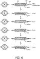
- the overlays in FIGS. 3 and 6 may have a green color to indicate low pressure conditions and a red color to indicate high pressure conditions for the inflatable medical instrument.
- the overlay 121 in FIG. 6 provides a clear visual guide concerning the real-time state of pressurization of the balloon catheter for the practitioner during an interventional procedure.
- the color of the overlay 121 also provides a clear warning to the practitioner concerning the existence of a high pressure condition in the medical instrument.
- the color mapping of the overlay can be specific to each balloon model (nominal pressure, burst pressure).
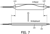
- the shape analysis module 114 is configured to analyze the FORS data 111 and determine one or more characteristics of the inflatable medical instrument by three-dimensional point tracking. More specifically, as shown in Fig. 7 , the shape analysis module 114 is configured to identify a point 122 at the beginning and at the end 124 of the medical device. These points may be input into a workstation 101 by the user through the interface 112. Alternatively, the points 122, 124 may be automatically identified by the system based on structural and/or positional characteristics of the inflatable medical instrument 102.
- the shape analysis module 114 is configured to determine the linear distance between the points 122, 124. During the interventional procedure, the shape analysis module 114 tracks points 122, 124 for changes in the linear distance between them. The changes in the length of the lumen between the two points 122, 124 in response to changes in the inflatable medical instrument 102 are analyzed by the shape analysis module 114 and characteristics concerning the medical instrument are determined based on these changes.
- the distance between two points 122, 124 at the beginning and end of a balloon catheter decreases as the balloon catheter inflates during a balloon angioplasty.
- This change in distance is then utilized by the shape analysis module to determine characteristics concerning the inflatable medical instrument. For instance, the diameter of the balloon catheter during a balloon angioplasty procedure may be obtained by analyzing the distance of the two points.
- a calibration model may be utilized for increased accuracy of the determinations by the shape analysis module 114.
- Calibrated models 130 may be in the form of a linear, polynomial, exponential, logarithmic, or other relationship, a lookup table 128, or some combined relationship thereof that relates a shape-derived calculation to the actual balloon state. Distance changes may be tracked by the shape analysis module 114 utilizing three-dimensional point tracking.
- the shape analysis module 114 is also configured to determine the status of the balloon concerning rupture based on the FORS data 111. More specifically, by monitoring the rate of changes of the inflatable medical instrument 102 concerning diameter and pressurization by analysis of the FORS data 111, an adverse event such as rupture may be detected by a high rate of change in these characteristics.
- Fig. 8 shows a graph of the normalized shape response of a balloon catheter before and after a balloon catheter rupture. After the rupture event, an approximate 50% decrease of the total response is exhibited within the first 30 milliseconds after the rupture.
- the system 100 may include a threshold value for the rate of a decrease in the shape response of a particular inflatable medical instrument.
- the system 100 is configured to produce an optical or auditory signal when a rupture is detected by the shape analysis module 114.
- the shape analysis module 114 is also configured to utilize the FORS data 111 to determine the position of the inflatable medical instrument 102.
- the localized shape change of the guidewire 104 based on the changes in the balloon lumen has a much higher amplitude than shape change in the surrounding areas of the subject during the inflation of device.
- the shape analysis module 114 is configured to receive an input from the user indicating that the inflation has begun. The shape analysis module then selects a baseline frame for the inflatable medical instrument for comparison. The shape analysis module 114 compares the curvature or other shape parameters during the procedure and computes a position of the inflatable medical instrument.
- Fig. 9 shows a graph of the curvature change for identification of the balloon position along the guidewire.
- the balloon position can be estimated by its endpoints, which are found to be the first point before and after the peak that drops below a certain threshold value determined by a balloon calibration.
- the center position of the balloon along the guidewire is identified as halfway between these points.
- the distance between the beginning and end point is determined by the shape analysis module 114 and a confidence score for the accuracy of the detected balloon position is generated.
- the position of the inflatable medical instrument may be used by the shape analysis module 114 to visualize the instrument and to register the position of the instrument in a global coordinate system for tracking purposes.
- the imaging module 120 may generate a graphical representation of the inflatable medical instrument 102 using the determined position of the instrument.
- the balloon position is identified using a longitudinal encoding device.
- the system 100 utilizes the FORS data to determine characteristics of the inflatable medical instrument 102 in a similar manner as described for the embodiments in which the optical fiber is within the guidewire 104.
- exemplary methods 140 for tracking an inflatable medical instrument 102 that is configured for an interventional procedure and determining characteristics of the instrument are illustratively shown in accordance with the present principles.
- a guidewire 104 is positioned within a lumen 116 of an inflatable medical instrument.
- a shape of the guidewire during an interventional procedure is determined by a FORS system.
- the FORS data 111 from the FORS system is analyzed.
- the FORS data 111 may be analyzed by a computation using curvature data or three-dimensional point tracking data for the inflatable instrument, as previously described with respect to the system 100 of the present invention.
- the inflatable medical instrument is tracked and characteristics of the inflatable medical instrument are determined based upon the FORS data 111 from the FORS system. For example, characteristics including the diameter of the inflatable instrument, the pressurization of the instrument and whether the instrument has ruptured may be determined in a manner previously described for the system 100 of the present invention. The position of the instrument may also be determined in order to track the instrument and register the instrument in a global coordinate system.
- the method includes the additional step of generating images based on the characteristics of the inflatable medical instrument.
- the images that are generated may be an overlay, a virtual image of the guidewire, a virtual image of the inflatable medical instrument, etc.
- FIG. 12 shows another embodiment of the exemplary method 140 for tracking an inflatable medical instrument 102 that is configured for an interventional procedure and determining characteristics of the instrument in accordance with the present principles.
- a stored lookup table is read in order to determine the model of the inflatable medical instrument.
- the lookup table is preferably stored in the memory 108 of the workstation 101.
- a segment of the optical fiber 107 of the FORS system 106 is located in the inflatable medical instrument during an interventional procedure.
- the optical fiber may be integrated in a guidewire that is positioned in the lumen of the inflatable medical instrument or the optical fiber may be imbedded directly in the inflatable medical instrument.
- a longitudinal encoding device and method is used to locate the optical fiber within the guidewire positioned in the lumen 116 of the inflatable medical instrument.
- a shape of the FORS device in the inflatable medical instrument during an interventional procedure is determined by a FORS system.
- the FORS data 111 from the FORS system is analyzed and characteristics of the inflatable medical instrument are determined based upon the FORS data 111 from the FORS system.
- the characteristics determined from the FORS data are input into the lookup table and the display of a virtual balloon is updated.
- the balloon model parameters may be further updated such as via fluoroscopy or user input.
- the virtual balloon is displayed as an overlay on the FORS device in the balloon segment. The overlay may be displayed on live or pre-operative images.
- FIG. 13 shows another embodiment of the exemplary method 140 for tracking an inflatable medical instrument 102 that is configured for an interventional procedure and determining characteristics of the instrument in accordance with the present principles.
- the model type of the inflatable instrument is identified either by the user, RFID technology or automatic detection.
- stored model parameters are read in order to determine the parameters for the model of the inflatable medical instrument.
- a segment of the optical fiber 107 of the FORS system 106 is located in the inflatable medical instrument during an interventional procedure by a longitudinal encoding device and method or by other means known in the art.
- a shape of the FORS device within the inflatable medical instrument during an interventional procedure is determined by a FORS system.
- the FORS data 111 from the FORS system is analyzed and characteristics of the inflatable medical instrument are determined based upon the FORS data 111 from the FORS system.
- the characteristics determined from the FORS data are placed into a parameterized model to update a display of a virtual balloon.
- the virtual balloon is displayed as an overlay on the FORS device in the balloon segment. The overlay may be displayed on live or pre-operative images.
- the balloon model parameters may be further updated such as via fluoroscopy or user input.
Landscapes
- Health & Medical Sciences (AREA)
- Life Sciences & Earth Sciences (AREA)
- Heart & Thoracic Surgery (AREA)
- Engineering & Computer Science (AREA)
- Animal Behavior & Ethology (AREA)
- Veterinary Medicine (AREA)
- Biomedical Technology (AREA)
- Public Health (AREA)
- General Health & Medical Sciences (AREA)
- Biophysics (AREA)
- Surgery (AREA)
- Molecular Biology (AREA)
- Medical Informatics (AREA)
- Anesthesiology (AREA)
- Hematology (AREA)
- Pulmonology (AREA)
- Pathology (AREA)
- Physics & Mathematics (AREA)
- Nuclear Medicine, Radiotherapy & Molecular Imaging (AREA)
- Child & Adolescent Psychology (AREA)
- Oral & Maxillofacial Surgery (AREA)
- Dentistry (AREA)
- Robotics (AREA)
- Gynecology & Obstetrics (AREA)
- Radiology & Medical Imaging (AREA)
- Vascular Medicine (AREA)
- Endoscopes (AREA)
- Media Introduction/Drainage Providing Device (AREA)
Claims (10)
- Medizinisches System, umfassend
ein aufblasbares medizinisches Instrument (102), das für eine interventionelle Entfaltung konfiguriert ist und eine optische Faser für ein FORS-System einschließt, wobei die optische Faser für das FORS-System in einen Führungsdraht (104) integriert ist, der in einem Lumen (116) des aufblasbaren medizinischen Instruments positioniert ist;
ein FORS-System (106), das konfiguriert ist, um eine Form des Führungsdrahtes zu messen, um eine Form des aufblasbaren medizinischen Instruments während der interventionellen Entfaltung zu bestimmen; und
ein Formanalysemodul (114), das konfiguriert ist, um FORS-Daten aus dem FORS-System zu analysieren und eine sofortige virtuelle Messung der Eigenschaften des aufblasbaren medizinischen Instruments zu bestimmen, wobei die Eigenschaften das Volumen des aufblasbaren medizinischen Instruments, einen Durchmesser des aufblasbaren medizinischen Instruments, einen Druck des aufblasbaren medizinischen Instruments und/oder eine Gesamtzahl von Aufblaszyklen für das aufblasbare medizinische Instrument umfassen. - System nach Anspruch 1, wobei das Formanalysemodul (114) konfiguriert ist, um Eigenschaften des aufblasbaren medizinischen Instruments durch Berechnen von Formparametern für das aufblasbare medizinische Instrument zu bestimmen, wobei die Formparameter eine Form, Krümmung, Knotenabstand, axiale Dehnung und/oder dreidimensionale Form des aufblasbaren medizinischen Instruments einschließen.
- System nach Anspruch 1, wobei das Formanalysemodul (114) zudem eine Nachschlagetabelle (128) oder ein Modell (130) zur Kalibrierung des aufblasbaren medizinischen Instruments einschließt.
- System nach Anspruch 1, wobei das Formanalysemodul (114) zudem konfiguriert ist, um die FORS-Daten zu analysieren und eine sofortige virtuelle Messung einer Position des aufblasbaren medizinischen Instruments zu bestimmen.
- System nach Anspruch 1, wobei das Formanalysemodul (114) konfiguriert ist, um die FORS-Daten zu analysieren und zu erkennen, ob das aufblasbare medizinische Instrument gerissen ist; und
das System ist so konfiguriert, dass es ein Signal erzeugt, falls ein Riss festgestellt wird. - System nach Anspruch 1, wobei:das System zudem eine Bildgebungsvorrichtung (120) einschließt, die konfiguriert ist, um ein Modell oder Bilder basierend auf den durch das Formanalysemodul bestimmten Eigenschaften zu erzeugen; unddas System ist so konfiguriert, dass das Modell oder die Bilder basierend auf Daten einer anderen Bildgebungsmodalität oder aufgrund einer Benutzereingabe aktualisiert werden.
- System nach Anspruch 6, wobei das System konfiguriert ist, um das Bild oder Modell auf einem präoperativen oder intraoperativen Bild zu überlagern.
- Medizinisches System nach Anspruch 1, zudem umfassend eine Arbeitsstation (101), einschließend:
einen oder mehrere Prozessoren (110), Speicher (108) und eine Schnittstelle (112); das Formanalysemodul (114). - System nach Anspruch 8, wobei das Formanalysemodul (114) konfiguriert ist, um Eigenschaften des aufblasbaren medizinischen Instruments durch Berechnen von Formparametern für das aufblasbare medizinische Instrument zu bestimmen.
- System von Anspruch 1
wobei das Formanalysemodul (114) zudem konfiguriert ist, um aus Daten von der optischen FORS-Faser eine Form der optischen FORS-Faser zu erkennen, wobei die Form für eine Änderung der Form des Lumens charakteristisch ist.
Applications Claiming Priority (2)
| Application Number | Priority Date | Filing Date | Title |
|---|---|---|---|
| US201562183942P | 2015-06-24 | 2015-06-24 | |
| PCT/EP2016/062979 WO2016206975A1 (en) | 2015-06-24 | 2016-06-08 | System and method for tracking and determining characteristics of inflatable medical instruments using fiber-optical realshape data |
Publications (2)
| Publication Number | Publication Date |
|---|---|
| EP3313498A1 EP3313498A1 (de) | 2018-05-02 |
| EP3313498B1 true EP3313498B1 (de) | 2020-05-20 |
Family
ID=56137288
Family Applications (1)
| Application Number | Title | Priority Date | Filing Date |
|---|---|---|---|
| EP16730298.3A Active EP3313498B1 (de) | 2015-06-24 | 2016-06-08 | System zur verfolgung und bestimmung der eigenschaften von aufblasbaren medizinischen instrumenten anhand von faseroptischen realshape-daten |
Country Status (4)
| Country | Link |
|---|---|
| US (1) | US11039890B2 (de) |
| EP (1) | EP3313498B1 (de) |
| JP (1) | JP6739454B2 (de) |
| WO (1) | WO2016206975A1 (de) |
Families Citing this family (19)
| Publication number | Priority date | Publication date | Assignee | Title |
|---|---|---|---|---|
| CN106618803B (zh) * | 2017-02-08 | 2018-10-02 | 上海纽脉太惟医疗科技有限公司 | 一种人工心脏瓣膜输送装置 |
| CN106580519B (zh) * | 2017-02-08 | 2018-06-19 | 上海纽脉太惟医疗科技有限公司 | 一种可测量球囊直径变化的医疗组件 |
| US10799256B2 (en) * | 2017-04-24 | 2020-10-13 | Biosense Webster (Israel) Ltd. | Mapping of nasal passages before and after a procedure |
| JP2021508586A (ja) | 2018-01-02 | 2021-03-11 | コーニンクレッカ フィリップス エヌ ヴェKoninklijke Philips N.V. | Ossインターベンショナルデバイスのアニメーション位置表示 |
| CN216090756U (zh) | 2019-08-12 | 2022-03-22 | 巴德阿克塞斯系统股份有限公司 | 医疗装置和用于医疗装置的形状感测系统 |
| EP3777782A1 (de) * | 2019-08-14 | 2021-02-17 | Biotronik Ag | Lernendes medizinisches system für eine optimale stenteinbettung bei der angioplastie |
| WO2021028152A1 (en) * | 2019-08-14 | 2021-02-18 | Biotronik Ag | Learning electronic balloon catheter system for optimal stent embedding |
| CN214804697U (zh) | 2019-11-25 | 2021-11-23 | 巴德阿克塞斯系统股份有限公司 | 光学尖端追踪系统 |
| EP4061272A4 (de) | 2019-11-25 | 2023-11-22 | Bard Access Systems, Inc. | Formungsempfindliche systeme mit filtern und verfahren dafür |
| EP4110175A1 (de) | 2020-02-28 | 2023-01-04 | Bard Access Systems, Inc. | Optische verbindungssysteme und verfahren dafür |
| CN113456054A (zh) | 2020-03-30 | 2021-10-01 | 巴德阿克塞斯系统股份有限公司 | 光学和电气诊断系统及其方法 |
| US20210330398A1 (en) * | 2020-04-22 | 2021-10-28 | St. Jude Medical International Holding S.À.R.L. | Single-core fiber and multi-core fiber configurations for medical devices |
| US11622816B2 (en) | 2020-06-26 | 2023-04-11 | Bard Access Systems, Inc. | Malposition detection system |
| CN216136534U (zh) | 2020-06-29 | 2022-03-29 | 巴德阿克塞斯系统股份有限公司 | 用于将医疗装置放置入患者身体内的医疗装置系统 |
| US11624677B2 (en) | 2020-07-10 | 2023-04-11 | Bard Access Systems, Inc. | Continuous fiber optic functionality monitoring and self-diagnostic reporting system |
| US11630009B2 (en) | 2020-08-03 | 2023-04-18 | Bard Access Systems, Inc. | Bragg grated fiber optic fluctuation sensing and monitoring system |
| CN216985791U (zh) | 2020-10-13 | 2022-07-19 | 巴德阿克塞斯系统股份有限公司 | 用于光纤连接器的消毒罩 |
| US20220110695A1 (en) * | 2020-10-13 | 2022-04-14 | Bard Access Systems, Inc. | Fiber Optic Enabled Deployable Medical Devices for Monitoring, Assessment and Capture of Deployment Information |
| ES1286945Y (es) * | 2022-01-13 | 2022-05-13 | Marin David Martinez | Dispositivo de inflado para angioplastia mediante regulación automática e inteligencia artificial |
Citations (1)
| Publication number | Priority date | Publication date | Assignee | Title |
|---|---|---|---|---|
| US20070032818A1 (en) * | 2005-08-05 | 2007-02-08 | Western Clinical Engineering Ltd. | Surgical tourniquet cuff for limiting usage to improve safety |
Family Cites Families (6)
| Publication number | Priority date | Publication date | Assignee | Title |
|---|---|---|---|---|
| EP2667816A2 (de) * | 2011-01-28 | 2013-12-04 | Koninklijke Philips N.V. | Formspeichernde glasfaser zur spitzen- und formcharakterisierung medizinischer instrumente |
| US8873900B2 (en) * | 2011-04-21 | 2014-10-28 | Medtronic Vascular, Inc. | Balloon catheter with integrated optical sensor for determining balloon diameter |
| EP3488803B1 (de) * | 2012-02-03 | 2023-09-27 | Intuitive Surgical Operations, Inc. | Lenkbare flexible nadel mit eingebetteter formerfassung |
| WO2014053941A1 (en) * | 2012-10-02 | 2014-04-10 | Koninklijke Philips N.V. | Volume mapping using optical shape sensors |
| US20160000519A1 (en) | 2013-03-28 | 2016-01-07 | Koninklijke Philips N.V. | Instrument localization in guided high dose rate brachytherapy |
| CN105636503B (zh) * | 2013-09-30 | 2019-05-21 | 皇家飞利浦有限公司 | 用于光学形状感测的多用途内腔设计 |
-
2016
- 2016-06-08 EP EP16730298.3A patent/EP3313498B1/de active Active
- 2016-06-08 JP JP2017566346A patent/JP6739454B2/ja active Active
- 2016-06-08 WO PCT/EP2016/062979 patent/WO2016206975A1/en active Application Filing
- 2016-06-08 US US15/736,854 patent/US11039890B2/en active Active
Patent Citations (1)
| Publication number | Priority date | Publication date | Assignee | Title |
|---|---|---|---|---|
| US20070032818A1 (en) * | 2005-08-05 | 2007-02-08 | Western Clinical Engineering Ltd. | Surgical tourniquet cuff for limiting usage to improve safety |
Also Published As
| Publication number | Publication date |
|---|---|
| JP6739454B2 (ja) | 2020-08-12 |
| EP3313498A1 (de) | 2018-05-02 |
| WO2016206975A1 (en) | 2016-12-29 |
| JP2018522638A (ja) | 2018-08-16 |
| US20180360545A1 (en) | 2018-12-20 |
| US11039890B2 (en) | 2021-06-22 |
Similar Documents
| Publication | Publication Date | Title |
|---|---|---|
| EP3313498B1 (de) | System zur verfolgung und bestimmung der eigenschaften von aufblasbaren medizinischen instrumenten anhand von faseroptischen realshape-daten | |
| US10994095B2 (en) | Hub for device placement with optical shape sensed guidewire | |
| US11547489B2 (en) | Shape sensing of multiple over-the-wire devices | |
| US11690975B2 (en) | Hub for device navigation with optical shape sensed guidewire | |
| US11576729B2 (en) | Cranial surgery using optical shape sensing | |
| US20150141764A1 (en) | Distributed sensing device for referencing of physiological features | |
| US11553966B2 (en) | Device visualization through optical shape sensing of a guidewire | |
| EP3247301B1 (de) | Endograftvisualisierung mit optischer formmessung | |
| US11346730B2 (en) | Systems and methods for determining the length of a non-shape-sensed interventional device with a shape-sensed guidewire and determining a state of the guidewire with respect to an interventional device | |
| US11730931B2 (en) | Balloon catheter comprising shape sensing optical fibers | |
| JP7216655B2 (ja) | Oss奥行短縮検出システム | |
| WO2014024069A1 (en) | Quantifying probe deflection for improved catheter identification | |
| US11344222B2 (en) | Systems and methods for determining the position of a non-shape-sensed guidewire with a shape-sensed catheter and for visualizing the guidewire | |
| US20180344204A1 (en) | Features for optical shape sense enabled device identification | |
| WO2012143883A2 (en) | Visible optical fiber for medical imaging applications | |
| WO2015092590A1 (en) | System and method for determining the entry point to the body using optical shape sensing |
Legal Events
| Date | Code | Title | Description |
|---|---|---|---|
| STAA | Information on the status of an ep patent application or granted ep patent |
Free format text: STATUS: THE INTERNATIONAL PUBLICATION HAS BEEN MADE |
|
| PUAI | Public reference made under article 153(3) epc to a published international application that has entered the european phase |
Free format text: ORIGINAL CODE: 0009012 |
|
| STAA | Information on the status of an ep patent application or granted ep patent |
Free format text: STATUS: REQUEST FOR EXAMINATION WAS MADE |
|
| 17P | Request for examination filed |
Effective date: 20180124 |
|
| AK | Designated contracting states |
Kind code of ref document: A1 Designated state(s): AL AT BE BG CH CY CZ DE DK EE ES FI FR GB GR HR HU IE IS IT LI LT LU LV MC MK MT NL NO PL PT RO RS SE SI SK SM TR |
|
| AX | Request for extension of the european patent |
Extension state: BA ME |
|
| DAV | Request for validation of the european patent (deleted) | ||
| DAX | Request for extension of the european patent (deleted) | ||
| STAA | Information on the status of an ep patent application or granted ep patent |
Free format text: STATUS: EXAMINATION IS IN PROGRESS |
|
| 17Q | First examination report despatched |
Effective date: 20190520 |
|
| REG | Reference to a national code |
Ref country code: DE Ref legal event code: R079 Ref document number: 602016036727 Country of ref document: DE Free format text: PREVIOUS MAIN CLASS: A61M0025100000 Ipc: A61B0005000000 |
|
| RIC1 | Information provided on ipc code assigned before grant |
Ipc: A61B 5/00 20060101AFI20191021BHEP Ipc: A61B 17/22 20060101ALI20191021BHEP Ipc: A61M 25/09 20060101ALI20191021BHEP Ipc: A61M 25/10 20130101ALI20191021BHEP Ipc: A61B 34/20 20160101ALN20191021BHEP |
|
| GRAP | Despatch of communication of intention to grant a patent |
Free format text: ORIGINAL CODE: EPIDOSNIGR1 |
|
| STAA | Information on the status of an ep patent application or granted ep patent |
Free format text: STATUS: GRANT OF PATENT IS INTENDED |
|
| RIC1 | Information provided on ipc code assigned before grant |
Ipc: A61B 5/00 20060101AFI20191111BHEP Ipc: A61B 34/20 20160101ALN20191111BHEP Ipc: A61B 17/22 20060101ALI20191111BHEP Ipc: A61M 25/10 20130101ALI20191111BHEP Ipc: A61M 25/09 20060101ALI20191111BHEP |
|
| INTG | Intention to grant announced |
Effective date: 20191205 |
|
| RAP1 | Party data changed (applicant data changed or rights of an application transferred) |
Owner name: KONINKLIJKE PHILIPS N.V. |
|
| GRAS | Grant fee paid |
Free format text: ORIGINAL CODE: EPIDOSNIGR3 |
|
| GRAA | (expected) grant |
Free format text: ORIGINAL CODE: 0009210 |
|
| STAA | Information on the status of an ep patent application or granted ep patent |
Free format text: STATUS: THE PATENT HAS BEEN GRANTED |
|
| AK | Designated contracting states |
Kind code of ref document: B1 Designated state(s): AL AT BE BG CH CY CZ DE DK EE ES FI FR GB GR HR HU IE IS IT LI LT LU LV MC MK MT NL NO PL PT RO RS SE SI SK SM TR |
|
| REG | Reference to a national code |
Ref country code: GB Ref legal event code: FG4D |
|
| REG | Reference to a national code |
Ref country code: CH Ref legal event code: EP |
|
| REG | Reference to a national code |
Ref country code: DE Ref legal event code: R096 Ref document number: 602016036727 Country of ref document: DE |
|
| REG | Reference to a national code |
Ref country code: AT Ref legal event code: REF Ref document number: 1272058 Country of ref document: AT Kind code of ref document: T Effective date: 20200615 |
|
| REG | Reference to a national code |
Ref country code: LT Ref legal event code: MG4D |
|
| REG | Reference to a national code |
Ref country code: NL Ref legal event code: MP Effective date: 20200520 |
|
| PG25 | Lapsed in a contracting state [announced via postgrant information from national office to epo] |
Ref country code: PT Free format text: LAPSE BECAUSE OF FAILURE TO SUBMIT A TRANSLATION OF THE DESCRIPTION OR TO PAY THE FEE WITHIN THE PRESCRIBED TIME-LIMIT Effective date: 20200921 Ref country code: FI Free format text: LAPSE BECAUSE OF FAILURE TO SUBMIT A TRANSLATION OF THE DESCRIPTION OR TO PAY THE FEE WITHIN THE PRESCRIBED TIME-LIMIT Effective date: 20200520 Ref country code: NO Free format text: LAPSE BECAUSE OF FAILURE TO SUBMIT A TRANSLATION OF THE DESCRIPTION OR TO PAY THE FEE WITHIN THE PRESCRIBED TIME-LIMIT Effective date: 20200820 Ref country code: GR Free format text: LAPSE BECAUSE OF FAILURE TO SUBMIT A TRANSLATION OF THE DESCRIPTION OR TO PAY THE FEE WITHIN THE PRESCRIBED TIME-LIMIT Effective date: 20200821 Ref country code: IS Free format text: LAPSE BECAUSE OF FAILURE TO SUBMIT A TRANSLATION OF THE DESCRIPTION OR TO PAY THE FEE WITHIN THE PRESCRIBED TIME-LIMIT Effective date: 20200920 Ref country code: SE Free format text: LAPSE BECAUSE OF FAILURE TO SUBMIT A TRANSLATION OF THE DESCRIPTION OR TO PAY THE FEE WITHIN THE PRESCRIBED TIME-LIMIT Effective date: 20200520 Ref country code: LT Free format text: LAPSE BECAUSE OF FAILURE TO SUBMIT A TRANSLATION OF THE DESCRIPTION OR TO PAY THE FEE WITHIN THE PRESCRIBED TIME-LIMIT Effective date: 20200520 |
|
| PG25 | Lapsed in a contracting state [announced via postgrant information from national office to epo] |
Ref country code: BG Free format text: LAPSE BECAUSE OF FAILURE TO SUBMIT A TRANSLATION OF THE DESCRIPTION OR TO PAY THE FEE WITHIN THE PRESCRIBED TIME-LIMIT Effective date: 20200820 Ref country code: LV Free format text: LAPSE BECAUSE OF FAILURE TO SUBMIT A TRANSLATION OF THE DESCRIPTION OR TO PAY THE FEE WITHIN THE PRESCRIBED TIME-LIMIT Effective date: 20200520 Ref country code: RS Free format text: LAPSE BECAUSE OF FAILURE TO SUBMIT A TRANSLATION OF THE DESCRIPTION OR TO PAY THE FEE WITHIN THE PRESCRIBED TIME-LIMIT Effective date: 20200520 Ref country code: HR Free format text: LAPSE BECAUSE OF FAILURE TO SUBMIT A TRANSLATION OF THE DESCRIPTION OR TO PAY THE FEE WITHIN THE PRESCRIBED TIME-LIMIT Effective date: 20200520 |
|
| REG | Reference to a national code |
Ref country code: AT Ref legal event code: MK05 Ref document number: 1272058 Country of ref document: AT Kind code of ref document: T Effective date: 20200520 |
|
| PG25 | Lapsed in a contracting state [announced via postgrant information from national office to epo] |
Ref country code: AL Free format text: LAPSE BECAUSE OF FAILURE TO SUBMIT A TRANSLATION OF THE DESCRIPTION OR TO PAY THE FEE WITHIN THE PRESCRIBED TIME-LIMIT Effective date: 20200520 Ref country code: NL Free format text: LAPSE BECAUSE OF FAILURE TO SUBMIT A TRANSLATION OF THE DESCRIPTION OR TO PAY THE FEE WITHIN THE PRESCRIBED TIME-LIMIT Effective date: 20200520 |
|
| PG25 | Lapsed in a contracting state [announced via postgrant information from national office to epo] |
Ref country code: EE Free format text: LAPSE BECAUSE OF FAILURE TO SUBMIT A TRANSLATION OF THE DESCRIPTION OR TO PAY THE FEE WITHIN THE PRESCRIBED TIME-LIMIT Effective date: 20200520 Ref country code: DK Free format text: LAPSE BECAUSE OF FAILURE TO SUBMIT A TRANSLATION OF THE DESCRIPTION OR TO PAY THE FEE WITHIN THE PRESCRIBED TIME-LIMIT Effective date: 20200520 Ref country code: AT Free format text: LAPSE BECAUSE OF FAILURE TO SUBMIT A TRANSLATION OF THE DESCRIPTION OR TO PAY THE FEE WITHIN THE PRESCRIBED TIME-LIMIT Effective date: 20200520 Ref country code: SM Free format text: LAPSE BECAUSE OF FAILURE TO SUBMIT A TRANSLATION OF THE DESCRIPTION OR TO PAY THE FEE WITHIN THE PRESCRIBED TIME-LIMIT Effective date: 20200520 Ref country code: IT Free format text: LAPSE BECAUSE OF FAILURE TO SUBMIT A TRANSLATION OF THE DESCRIPTION OR TO PAY THE FEE WITHIN THE PRESCRIBED TIME-LIMIT Effective date: 20200520 Ref country code: ES Free format text: LAPSE BECAUSE OF FAILURE TO SUBMIT A TRANSLATION OF THE DESCRIPTION OR TO PAY THE FEE WITHIN THE PRESCRIBED TIME-LIMIT Effective date: 20200520 Ref country code: CZ Free format text: LAPSE BECAUSE OF FAILURE TO SUBMIT A TRANSLATION OF THE DESCRIPTION OR TO PAY THE FEE WITHIN THE PRESCRIBED TIME-LIMIT Effective date: 20200520 Ref country code: RO Free format text: LAPSE BECAUSE OF FAILURE TO SUBMIT A TRANSLATION OF THE DESCRIPTION OR TO PAY THE FEE WITHIN THE PRESCRIBED TIME-LIMIT Effective date: 20200520 |
|
| REG | Reference to a national code |
Ref country code: CH Ref legal event code: PL |
|
| REG | Reference to a national code |
Ref country code: DE Ref legal event code: R097 Ref document number: 602016036727 Country of ref document: DE |
|
| PG25 | Lapsed in a contracting state [announced via postgrant information from national office to epo] |
Ref country code: PL Free format text: LAPSE BECAUSE OF FAILURE TO SUBMIT A TRANSLATION OF THE DESCRIPTION OR TO PAY THE FEE WITHIN THE PRESCRIBED TIME-LIMIT Effective date: 20200520 Ref country code: MC Free format text: LAPSE BECAUSE OF FAILURE TO SUBMIT A TRANSLATION OF THE DESCRIPTION OR TO PAY THE FEE WITHIN THE PRESCRIBED TIME-LIMIT Effective date: 20200520 Ref country code: SK Free format text: LAPSE BECAUSE OF FAILURE TO SUBMIT A TRANSLATION OF THE DESCRIPTION OR TO PAY THE FEE WITHIN THE PRESCRIBED TIME-LIMIT Effective date: 20200520 |
|
| PLBE | No opposition filed within time limit |
Free format text: ORIGINAL CODE: 0009261 |
|
| STAA | Information on the status of an ep patent application or granted ep patent |
Free format text: STATUS: NO OPPOSITION FILED WITHIN TIME LIMIT |
|
| PG25 | Lapsed in a contracting state [announced via postgrant information from national office to epo] |
Ref country code: LU Free format text: LAPSE BECAUSE OF NON-PAYMENT OF DUE FEES Effective date: 20200608 |
|
| REG | Reference to a national code |
Ref country code: BE Ref legal event code: MM Effective date: 20200630 |
|
| 26N | No opposition filed |
Effective date: 20210223 |
|
| PG25 | Lapsed in a contracting state [announced via postgrant information from national office to epo] |
Ref country code: IE Free format text: LAPSE BECAUSE OF NON-PAYMENT OF DUE FEES Effective date: 20200608 Ref country code: CH Free format text: LAPSE BECAUSE OF NON-PAYMENT OF DUE FEES Effective date: 20200630 Ref country code: LI Free format text: LAPSE BECAUSE OF NON-PAYMENT OF DUE FEES Effective date: 20200630 |
|
| PG25 | Lapsed in a contracting state [announced via postgrant information from national office to epo] |
Ref country code: BE Free format text: LAPSE BECAUSE OF NON-PAYMENT OF DUE FEES Effective date: 20200630 Ref country code: SI Free format text: LAPSE BECAUSE OF FAILURE TO SUBMIT A TRANSLATION OF THE DESCRIPTION OR TO PAY THE FEE WITHIN THE PRESCRIBED TIME-LIMIT Effective date: 20200520 |
|
| PG25 | Lapsed in a contracting state [announced via postgrant information from national office to epo] |
Ref country code: TR Free format text: LAPSE BECAUSE OF FAILURE TO SUBMIT A TRANSLATION OF THE DESCRIPTION OR TO PAY THE FEE WITHIN THE PRESCRIBED TIME-LIMIT Effective date: 20200520 Ref country code: MT Free format text: LAPSE BECAUSE OF FAILURE TO SUBMIT A TRANSLATION OF THE DESCRIPTION OR TO PAY THE FEE WITHIN THE PRESCRIBED TIME-LIMIT Effective date: 20200520 Ref country code: CY Free format text: LAPSE BECAUSE OF FAILURE TO SUBMIT A TRANSLATION OF THE DESCRIPTION OR TO PAY THE FEE WITHIN THE PRESCRIBED TIME-LIMIT Effective date: 20200520 |
|
| PG25 | Lapsed in a contracting state [announced via postgrant information from national office to epo] |
Ref country code: MK Free format text: LAPSE BECAUSE OF FAILURE TO SUBMIT A TRANSLATION OF THE DESCRIPTION OR TO PAY THE FEE WITHIN THE PRESCRIBED TIME-LIMIT Effective date: 20200520 |
|
| PGFP | Annual fee paid to national office [announced via postgrant information from national office to epo] |
Ref country code: FR Payment date: 20230622 Year of fee payment: 8 Ref country code: DE Payment date: 20230627 Year of fee payment: 8 |
|
| PGFP | Annual fee paid to national office [announced via postgrant information from national office to epo] |
Ref country code: GB Payment date: 20230620 Year of fee payment: 8 |