EP3312650A2 - Glasfaserarraykonnektivitätssystem für mehrere transceiver und/oder mehrere fernkabel - Google Patents
Glasfaserarraykonnektivitätssystem für mehrere transceiver und/oder mehrere fernkabel Download PDFInfo
- Publication number
- EP3312650A2 EP3312650A2 EP17203977.8A EP17203977A EP3312650A2 EP 3312650 A2 EP3312650 A2 EP 3312650A2 EP 17203977 A EP17203977 A EP 17203977A EP 3312650 A2 EP3312650 A2 EP 3312650A2
- Authority
- EP
- European Patent Office
- Prior art keywords
- transceiver
- trunk
- end terminal
- fiber
- terminal
- Prior art date
- Legal status (The legal status is an assumption and is not a legal conclusion. Google has not performed a legal analysis and makes no representation as to the accuracy of the status listed.)
- Pending
Links
Images









Classifications
-
- G—PHYSICS
- G02—OPTICS
- G02B—OPTICAL ELEMENTS, SYSTEMS OR APPARATUS
- G02B6/00—Light guides; Structural details of arrangements comprising light guides and other optical elements, e.g. couplings
- G02B6/24—Coupling light guides
- G02B6/26—Optical coupling means
- G02B6/28—Optical coupling means having data bus means, i.e. plural waveguides interconnected and providing an inherently bidirectional system by mixing and splitting signals
-
- G—PHYSICS
- G02—OPTICS
- G02B—OPTICAL ELEMENTS, SYSTEMS OR APPARATUS
- G02B6/00—Light guides; Structural details of arrangements comprising light guides and other optical elements, e.g. couplings
- G02B6/44—Mechanical structures for providing tensile strength and external protection for fibres, e.g. optical transmission cables
- G02B6/4439—Auxiliary devices
- G02B6/4471—Terminating devices ; Cable clamps
- G02B6/4472—Manifolds
-
- G—PHYSICS
- G02—OPTICS
- G02B—OPTICAL ELEMENTS, SYSTEMS OR APPARATUS
- G02B6/00—Light guides; Structural details of arrangements comprising light guides and other optical elements, e.g. couplings
- G02B6/24—Coupling light guides
- G02B6/36—Mechanical coupling means
- G02B6/3608—Fibre wiring boards, i.e. where fibres are embedded or attached in a pattern on or to a substrate, e.g. flexible sheets
Definitions
- the present invention is directed generally to fiber optic multi-strand cables, connectors, adapters, and patching systems.
- Optical fibers are commonly used for the transmission of signals of all sorts, including communication and data signals.
- Communications systems often transmit signals between transceivers (i . e., devices that can both transmit and receive optical signals) via different fibers in each direction. More specifically, one or more fibers will transmit signals from the first transceiver to the second, and one or more of the other fibers will transmit signals from the second transceiver to the first. In this manner, optical signals are not traveling along the same fiber in different directions.
- a common optical system includes multiple transceivers at one end, 2-fiber patch cords that are connected to the transceivers and to duplex adapters mounted on a patch panel, a fan-out transition device connected to the duplex adapters that connects to a multi-strand fiber optic trunk cable (12 fibers per cable is common, and the fiber strands may be in ribbon form) via an array adapter, a second fan-out transition device connected to the opposite end of the optic trunk cable via a second array adapter, and corresponding transceivers connected via 2-fiber patch cords to the second fan-out transition device through duplex adapters.
- transceivers may utilize less than all of the fibers of the trunk cable.
- a transceiver may have only four channels, each of which has a "transmit" fiber and a "receive" fiber.
- two such transceivers would utilize the outer four fibers on either end of a 12-fiber trunk cable; i.e., the transmit fibers would use fibers 1-4 of the trunk cable, and the receive fibers would use fibers 9-12 of the trunk cable.
- the devices would occupy only eight of the 12 fibers of a 12-fiber trunk cable, which would result in inefficient use of the trunk cable.
- adding more transceivers onto the trunk cable in order to utilize all of the trunk cable fibers may complicate the connection scheme. As such, it may be desirable to provide schemes and accompanying devices that enable multiple transceivers having fewer than 12 fibers to connect with proper polarity via an available 12-fiber trunk cable.
- a different situation may also arise when a transceiver has more than 6 channels (12 fibers); for example, a pair of transceivers may have 12 or 18 channels. It may also be desirable to provide schemes and devices that enable such transceiver to utilize 12-fiber trunk cables.
- embodiments of the present invention are directed to a transition device for an optical fiber connection system adapted to interconnect a trunk cable with a plurality of transceivers.
- the transition device comprises: a first set of at least four optical fibers, each of the optical fibers having a trunk end and a transceiver end; a single trunk end terminal having a plurality of trunk ports arranged in a first row, each port connected with a respective one of the set of optical fibers at its trunk end, wherein a first axis of symmetry divides the ports; and a plurality of transceiver end terminals, each of the transceiver end terminals having even numbers of transceiver ports, each of the transceiver ports receiving a respective one of the set of optical fibers at their transceiver ends.
- each transceiver end terminal meet either of the following two conditions: (a) a first fiber originates from a first port in the trunk end terminal, and a second fiber originates from a second port in the trunk end terminal that is positioned at the mirror image location of the first port about the first axis of symmetry; or (b) each fiber is received in a first transceiver end terminal that has a corresponding second transceiver end terminal with the same number and arrangement of transceiver ports, and each fiber received in the first transceiver end terminal originates from a port in the trunk end terminal that has a mirror image port about the first axis of symmetry from which a fiber that is received in the second transceiver end terminal originates.
- embodiments of the present invention are directed to a telecommunications system comprising: a trunk cable comprising at least four optical fibers and terminals at opposite ends of the fibers, the terminals including a plurality of ports arranged in a row or multiple rows and divided by respective axis of symmetry, each of the optical fibers being associated with a respective one of the trunk terminal ports, and arranged so that the position of the trunk port on one end of a fiber is in the mirror image position about the respective axis of symmetry to the position of the trunk port on the opposite end of the fiber; and two identically arranged transition devices of the type described in the first aspect.
- the transition devices are connected to the opposite ends of the trunk cable such that the ports of the trunk cable terminals are aligned with the ports of the transition device trunk end terminals. Keying may be used on the end terminals and within the aligning adapters to ensure the intended orientation of the mated end terminals to each other.
- embodiments of the present invention are directed to a transition device for an optical fiber connection system adapted to interconnect a plurality of trunk cables with a single transceiver.
- the transition device comprises: a first set of at least four optical fibers, each of the optical fibers having a trunk end and a transceiver end; a single transceiver end terminal having a plurality of transceiver ports, possibly arranged in a multiple rows, each port connected with a respective one of the set of optical fibers at its transceiver end, wherein a first axis of symmetry divides the ports; and a plurality of trunk end terminals, each of the trunk end terminals having a plurality of trunk ports possibly arranged in a single row, each of the trunk ports receiving a respective one of the set of optical fibers at its trunk end.
- the arrangement of fibers in the transition device is configured such that the order of optical fibers within the trunk end terminals and the order of the trunk end terminals with respect to each other are arranged to produce a mirror image pattern of symmetry, the symmetry being achieved when transmitting fibers and corresponding receiving fibers are located in their respective mirror image positions about the centerline of a generally horizontally arranged array of the trunk end terminations.
- embodiments of the present invention are directed to a telecommunications system, comprising: at least two trunk cables each comprising at least four optical fibers and terminals at opposite ends of the fibers, the terminals including a plurality of ports, possibly arranged in a single row, and divided by respective axis of symmetry, each of the optical fibers being associated with a respective one of the trunk terminal ports, and arranged so that the position of the trunk port on one end of a fiber is in the mirror image position about the respective axis of symmetry to the position of the trunk port on the opposite end of the fiber; and two identically arranged transition devices of the type and meeting the conditions described in the third aspect.
- the transition devices are connected to the opposite ends of the trunk cables such that the ports of the trunk cable terminals are aligned with the ports of the transition device trunk end terminals. Keying may be used on the end terminals and within the aligning adapters to ensure the intended orientation of the mated end terminals to each other.
- the transition devices are configured such that the order of optical fibers within the trunk end terminals and the order of the trunk end terminals with respect to each other within both transition devices are arranged to produce a mirror image pattern of symmetry, the symmetry being achieved when transmitting fibers and corresponding receiving fibers are located in their respective mirror image positions about the centerline of a generally horizontally arranged array of the trunk end terminations.
- spatially relative terms such as “under”, “below”, “lower”, “over”, “upper” and the like, may be used herein for ease of description to describe one element or feature's relationship to another element(s) or feature(s) as illustrated in the figures. It will be understood that the spatially relative terms are intended to encompass different orientations of the device in use or operation in addition to the orientation depicted in the figures. For example, if the device in the figures is turned over, elements described as “under” or “beneath” other elements or features would then be oriented “over” the other elements or features. Thus, the exemplary term “under” can encompass both an orientation of over and under. The device may be otherwise oriented (rotated 90 degrees or at other orientations) and the spatially relative descriptors used herein interpreted accordingly.
- the fiber arrangement includes ports 1 through 12 arranged in a single horizontal row.
- fibers 1-4 may be used for receipt for channels 1-4, and fibers 9-12 may be used for transmission for channels 4-1. In such an instance, fibers 5-8 would be unused.
- the port arrangement of this terminal contains a vertical axis of symmetry, A1, which divides the interface between the center port positions 6 and 7.
- each transmitter port can be associated with a corresponding receiver port located in the symmetrical position across the axis A1
- each unused port can be associated with a corresponding unused port located in the symmetrical position across the axis A1 .
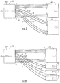
- a transition device in the form of a fan-out unit, designated broadly at 100, is shown therein.
- a terminal 102 that is configured to be connected with a 12-fiber trunk cable (such as cable 200 shown in Figure 3 ) has twelve ports arranged in a row that are associated with twelve fibers 1-12.
- the trunk end terminal 102 includes an alignment key 102k on its upper surface to ensure proper alignment with the trunk cable (the configuration of the alignment key 102k will be well understood to those skilled in this art and need not be described in detail herein).
- each of the terminals 104, 106, 108 may be sized to fit a 12-fiber adapter on a transceiver. However, each terminal receives only four of the 12 fibers that originate in the trunk end terminal 102. More specifically, fibers 1-4 are routed to the terminal 104, where they occupy, respectively, ports 12, 11, 2 and 1 of the terminal 104. Fibers 5-8 are routed to the terminal 106, where they occupy ports 12, 11, 2 and 1 thereof. Finally, fibers 9-12 are routed to the terminal 108 where they occupy ports 12, 11, 2 and 1 thereof. Importantly, the arrangement of occupied ports within terminals 104 and 108 is the same. Also, each of the terminals 104, 106, 108 includes a respective alignment key 104k, 106k, 108k on its upper surface.
- the terminals 104 and 108 receive fibers that originate from "mirror image" ports on terminal 102. More specifically, assuming the presence of an axis of symmetry A2 that extends vertically between the ports from which fibers 6 and 7 originate ( see axis of symmetry A1 in Figure 1 ), fibers 1-4 connect with terminal 104, and mirror image fibers 9-12 ( i.e., ports that are the mirror image of ports 1-4 across the axis of symmetry A2 ) connect with terminal 108. It can also be seen that the terminal 106 receives only fibers that originate from ports that have mirror image ports associated with other fibers received in the terminal 106. That is, fibers originating from ports 5 and 6 have mirror image fibers that originate from ports 7 and 8.
- the transition device when a transition device has fibers and terminals that follow one of the two conditions described above, the transition device can be employed in a telecommunication system that includes multiple transceivers that require fewer than all of the fibers of a connecting trunk cable, and that the same transition device can be employed on both ends of the trunk cable (thereby simplifying manufacturing, connectivity, and the like).
- each of the transceiver end terminals either (a) receives fibers that originate from mirror image ports in the trunk end terminal (as is the case with the transceiver end terminal 106 described above), or (b) has a corresponding transceiver end terminal with the same arrangement of occupied ports, wherein the corresponding transceiver end terminal receives fibers that originate from mirror image ports in the trunk end terminal (as is the case with the transceiver end terminals 104, 108 above).
- the system 150 includes a trunk cable 200 that includes twelve optical fibers 201-212 that extend between terminals 214, 216.
- An exemplary trunk cable is discussed in U.S. Patent No. 7,184,635 to Livingston , the disclosure of which is hereby incorporated herein in its entirety.
- Each of the terminals 214, 216 includes a key 214k, 216k on its upper surface.
- the terminals 214, 216 are inserted into "key-up to key-up" (i.e. aligned key) array adapters 220, 222 ( e . g ., MPO-type adapters).
- a transition device 100 is attached to the adapter 220 via the insertion of the trunk end terminal 102 into the adapter 220.
- the transceiver end terminals 104, 106, 108 are connected with, respectively, transceivers 230 , 232 , 234 , with their keys 104k, 106k, 108k being received in corresponding "key-up to key-up" receptacles in the transceivers 230, 232, 234.
- the trunk end terminal 102' of a second identical transition device 100' is connected to the terminal 216 of the trunk cable 200 via the array adapter 222.
- Transceiver end terminals 108', 106', 104' are connected to transceivers 240, 242, 244 with their alignment keys 108k', 106k', 104k' received in receptacles therein.
- the fiber designated as fiber 1 in the transition device 100 extends from the leftmost port of the terminal 102, whereas the fiber designated as fiber 1 in the transition device 100' extends from the rightmost port of its terminal 102' because the transition device 100' is inverted 180 degrees from the orientation of transition device 100.
- transceivers 230, 232, 234 to communicate with the transceivers 240, 242, 244.
- a signal is transmitted from transmitter T1 and travels along the leftmost fiber (labeled fiber 12 in Figure 3 ) that exits transceiver end terminal 104 to the port labeled position 1 in the trunk end terminal 102. From here, the signal travels through the terminal 214 of the trunk cable 200 to the leftmost fiber 201 thereof.
- the signal exits the leftmost port of the terminal 216 and enters the leftmost port of the trunk end terminal of the transition device 100' (labeled position 12 in Figure 3 ).
- the signal then travels along the leftmost fiber to the terminal 108' of the transition device, entering the leftmost port (labeled 1 in Figure 3 ), where it reaches receiver R1 of the transceiver 240.
- a return signal can then be transmitted from transmitter T1 of transceiver 240 to receiver R1 of the transceiver 230 .
- the signal generated by T1 travels through the rightmost port (labeled position 12 in Figure 3 ) of the transceiver end terminal 108' of the transition device 100', then through the rightmost fiber exiting the terminal 108' to the fourth port from the left (labeled position 9 in Figure 3 ) of the trunk end terminal 102'.
- the signal then enters the terminal 216 of trunk cable 200 at the fourth position from the left and travels through the corresponding fiber 204 to the terminal 214, exiting the port (labeled 9 in Figure 3 ) that is fourth from the left.
- the signal then enters the trunk end terminal 102 of the transition device 100 through the fourth port from the left (labeled position 4 in Figure 3 ) and travels along the rightmost fiber connected to the terminal 104 and enters the rightmost port thereof (labeled position 1). From there, the signal passes through the terminal 104, enters the transceiver 230, and is received in the receiver R1.
- signals can be passed from the transmitter T1 of transceiver 230 to the receiver R1 of transceiver 240, and from the transmitter T1 of transceiver 240 to the receiver R1 of transceiver 230, thereby forming a complete transmit/receive channel between these devices.
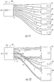
- a transition device 250 includes a trunk end terminal 252, a transceiver end terminal 254 that receives 10 of the 12 fibers that originate at the trunk end terminal 252, and a transceiver end terminal 256 that receives the other 2 fibers from the trunk end terminal 252.
- the transceiver end terminal 254 receives fibers 1-5 and 8-12 (which are sets of mirror image fibers), and transceiver end terminal 256 receives fibers 6 and 7, which are also mirror image fibers.
- both terminals meet condition (a) above, with the result that proper polarity for attached transceivers can be maintained using two of these devices on either end of a trunk cable such as trunk cable 200.
- the device 300 includes a trunk end terminal 302 and three transceiver end terminals 304, 306, 308.
- Transceiver end terminal 304 receives eight fibers from trunk end terminal 302: fibers 1-4 and mirror image fibers 9-12.
- Transceiver end terminals 306, 308 receive two fibers each from trunk end terminal 302; transceiver end terminal 306 receives fibers 5 and 6, and transceiver end terminal 308 receives fibers 7 and 8 that are mirror image fibers of fibers 5 and 6.
- transceiver end terminal 304 meets condition (a) above, and transceiver end terminals 306, 308 meet condition (b) above, so the device 300 can maintain proper polarity for attached transceivers if two such devices were attached at the ends of a trunk cable such as trunk cable 200.
- a device 350 includes a trunk end terminal 352, an eight fiber (four channel) terminal 354, and a four fiber (two channel) terminal 356.
- the fibers of transceiver end terminal 354 originate from ports 1-4 and 9-12 of trunk end terminal 352, thus satisfying condition (a) above, and the fibers of transceiver end terminal 356 originate from ports 5-8, thus also satisfying condition (a).
- two of these devices can maintain proper polarity for attached transceivers if used at opposite ends of a trunk cable such as trunk cable 200.
- a device 400 includes a trunk end terminal 402, a six fiber transceiver end terminal 404 that receives fibers 1-3 and 10-12 from terminal 402, and a six fiber transceiver end terminal 406 that receives fibers 4-9 from terminal 402. Because both transceiver end terminals 404, 406 satisfy condition (a), two of the devices 400 may be used on either end of a trunk cable such as trunk cable 200 and maintain proper polarity for attached transceivers.
- a device 450 has a trunk end terminal 452, a six-fiber transceiver end terminal 454, and three two-fiber transceiver end terminals 456, 458, 460.
- the transceiver end terminal 454 receives fibers 1-3 and 10-12 from trunk end terminal 452, satisfying condition (a).
- the transceiver end terminals 456 and 460 receive, respectively, the fibers 4 and 5 and the fibers 8 and 9, which are mirror image fibers, thereby satisfying condition (b).
- Transceiver end terminal 458 receives fibers 6 and 7, which satisfies condition (a). Because all of the transceiver end terminals 454, 456, 458, 460 satisfy either condition (a) or condition (b), two devices 450 can be attached to either end of a trunk cable such as trunk cable 200 and maintain proper polarity for attached transceivers.
- a device 550 disclosed therein includes a trunk end terminal 552, two transceiver end terminals 554, 556, each of which receives four fibers, and two transceiver end terminals 558, 560, each of which receives two fibers.
- the transceiver end terminal 554 receives fibers 1-4, while the transceiver end terminal 556 receives mirror image fibers 9-12, such that these two transceiver end terminals 554, 556 satisfy condition (b) above.
- the transceiver end terminal 558 receives fibers 5 and 6 and the transceiver end terminal 560 receives mirror image fibers 7 and 8, such that these two transceiver end terminals 558, 560 also satisfy condition (b).
- two devices 550 can be attached to the ends of a trunk cable such as trunk cable 200 and provide proper polarity for attached transceivers.
- Figure 10 illustrates a transition device 600, which includes a trunk end terminal 602, four two fiber transceiver end terminals 604, 606, 610, 612, and a four fiber transceiver end terminal 608.
- the transceiver end terminals 604 and 612 receive mirror image couplets of fibers 1 and 2 and fibers 11 and 12, respectively.
- the transceiver end terminals 606 and 610 receive mirror image couplets of fibers 3 and 4 and fibers 9 and 10, respectively.
- the transceiver end terminal 608 receives fibers 5-8. Because the terminals 604, 606, 610 and 612 meet condition (b), and terminal 608 meets condition (a), two devices 600 can maintain proper polarity for attached transceivers when used on either end of a trunk cable such as trunk cable 200.
- the device 650 illustrated therein includes a trunk end terminal 652 and six transceiver end terminals 654, 656, 658, 660, 662, 664.
- the transceiver end terminals 654, 656, 658, 660, 662, 664 receive, respectively, fibers 1 and 2, 3 and 4, 5 and 6, 7 and 8, 9 and 10, and 11 and 12.
- Transceiver end terminals 654 and 664 receive mirror image fibers, as do transceiver end terminals 656, 662 and transceiver end terminals 658, 660. Because all of the transceiver end terminals meet condition (b), two devices 650 may be employed on either end of a trunk cable such as trunk cable 200 and maintain proper polarity for attached transceivers.
- Figure 12 illustrates a device 700 that includes a trunk end terminal 702 and three transceiver end terminals: a six fiber terminal 704; a two fiber terminal 706; and a four fiber terminal 708.
- the transceiver end terminal 704 receives mirror image fibers 1-3 and 10-12
- the terminal 706 receives mirror image fibers 6 and 7
- the transceiver end terminal 708 receives mirror image fibers 4, 5, 8, and 9. Because all three transceiver end terminals 704, 706, 708 meet condition (a), the device 700 is suitable for use at either end of a trunk cable such as trunk cable 200 to maintain proper polarity for attached transceivers.
- Figure 13 illustrates a communication system 150' that employs two identical devices 700, 700' that connect transceivers 270, 272, 274 with transceivers 280, 278, 276, respectively, through a trunk cable 200.
- the maintenance of polarity between the transceivers can be seen by tracing a signal through each of the proposed channels. For example, starting with the leftmost port of the six-fiber transceiver 270, a signal is transmitted from transmitter T1 through the transceiver end terminal 704 and travels along the leftmost fiber (labeled fiber 12 in Figure 13 ) that exits transceiver end terminal 704 to the port labeled position 1 in the trunk end terminal 702.
- the signal travels through the terminal 214 of the trunk cable 200 to the leftmost fiber 201 thereof. Continuing along this path, the signal exits the leftmost port of the terminal 216 and enters the leftmost port of the trunk end terminal 702' of the transition device 700' (labeled position 12 in Figure 13 ). The signal then travels along the leftmost fiber to the terminal 704' of the transition device 700', entering the leftmost port (labeled 1 in Figure 13 ), where it reaches receiver R1 of the transceiver 280.
- a return signal can then be transmitted from transmitter T1 of transceiver 280 to receiver R1 of the transceiver 270.
- the signal generated by T1 travels through the rightmost port (labeled position 12 in Figure 13 ) of the transceiver end terminal 704' of the transition device 700', then through the rightmost fiber exiting the terminal 704' to the rightmost port (labeled position 1 in Figure 13 ) of the trunk end terminal 702'.
- the signal then enters the terminal 216 of trunk cable 200 at the rightmost position and travels through the corresponding fiber 212 to the terminal 214, exiting the rightmost port (labeled 1 in Figure 13 ).
- the signal then enters the trunk end terminal 702 of the transition device 700 through the rightmost port (labeled position 12 in Figure 13 ), travels along the rightmost fiber connected to the terminal 704, and enters the rightmost port thereof (labeled position 1). From there, the signal passes through the terminal 704, enters the transceiver 270, and is received in the receiver R1 .
- signals can be passed from the transmitter T1 of transceiver 270 to the receiver R1 of transceiver 280, and from the transmitter T1 of transceiver 280 to the receiver R1 of transceiver 270, thereby forming a complete transmit/receive channel between these devices.
- transceivers 272, 278 form one transmit/receive channel
- transceivers 274, 276 form two transmit/receive channels.
- the interconnection of the transceivers in a "key-up to key-up" arrangement can be accomplished with two identical transition devices 700, 700'.
- a transition device 100" is shown in the form of a cassette, with a housing 140 having a wall 141 in which an adapter 143 and the trunk end terminal 102 are mounted and an opposing wall 142 in which adapters 144, 145, 146 and the transceiver end terminals 104, 106, 108 are mounted.
- This configuration may be preferred for some applications.
- a fan-out configuration in which the terminals are not mounted in a wall, but instead are freely movable relative to each other, may be preferred.
- the device 750 differs from the previously discussed devices in that it has 24, rather than 12, fibers, and these fibers are arranged in two rows rather than one.
- the device 750 includes a trunk end terminal 752 from which the fibers originate.
- the trunk end terminal 752 is configured to connect with a 24-fiber trunk cable.
- the upper row of fibers is labeled 1-12 from right to left, and the lower row of fibers is labeled 13-24 from right to left.
- the device 752 includes six transceiver end terminals: terminals 754 and 764 that receive six fibers each; terminals 756 and 762 that receive four fibers each; and terminals 758 and 760 that receive two fibers each.
- the fibers are routed from the trunk end terminal 752 to the transceiver end terminals 754-764 in a pattern that repeats on each row to illustrate stacking of the routing of the transition device of Figure 12 within a multi-row trunk end terminal.
- Any of the transition device routings of Figures 2 and 4 -12 may be mixed within the multi-row trunk terminal, each one occupying a row unto itself.
- the complete transition device exhibits an axis of symmetry A3 and the rows comply with either or both of conditions (a) and (b).
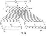
- FIG. 16 An alternative 24-fiber transition device is shown in Figure 16 and designated broadly at 800.
- the device 800 has a trunk end terminal 802 with 24 fibers originating from two rows.
- Two transceiver end terminals 804, 806 receive twelve fibers each, with the transceiver end terminal 804 receiving fibers 1-12 and the transceiver end terminal 806 receiving fibers 13-24.
- Fibers 1-12 are routed to terminal 804 in a way that is compliant to condition (a) about the axis of symmetry A3'.
- fibers 13-24 are routed to terminal 805 in a way that is compliant to condition (a) about the axis of symmetry A3'.
- FIG 17 an additional embodiment of a 24 fiber transition device, designated broadly at 900, is shown therein.
- the device 900 is configured to connect with a 24-fiber transceiver and to two 12-fiber trunk cables. This device may be useful to provide connectivity between transceivers having transmit and receive ports symmetrically arranged about the vertical axis of symmetry A5.
- the transition device 900 includes two trunk end terminals 902, 903 that receive 12 fibers each in a single row, and further includes a transceiver end terminal 904 that can connect with a 24-fiber transceiver.
- the 24 fibers that exit the transceiver end terminal 904 are routed to the trunk end terminals 902, 903 as mirror images of each other about the vertical axis of symmetry A5.
- fibers 1-6 of the top row of transceiver end terminal 904 are routed to positions 7-12 of the trunk end terminal 903, whereas fibers 7-12 of the transceiver end terminal 904 are routed to mirror image positions 1-6 of trunk end terminal 902, and fibers 13-18 of the lower row of transceiver end terminal 904 are routed to positions 1-6 of trunk end terminal 903, whereas fibers 19-24 are routed to mirror image positions 7-12 of trunk end terminal 902.
- the transceiver end terminals 902, 903 may be connected by a strap 905 that maintains the physical relationship of the terminals to each other.
- transition devices are configured such that the order of optical fibers within the trunk end terminals and the order of the trunk end terminals with respect to each other within both transition devices are arranged to produce a mirror image pattern of symmetry, the symmetry being achieved when transmitting fibers and corresponding receiving fibers are located in their respective mirror image positions about the centerline of a generally horizontally arranged array of the trunk end terminations.
- each trunk end terminal meet either of the following three conditions: (i) a first fiber originates from a first port in the transceiver end terminal, and a second fiber originates from a second port in the transceiver end terminal that is positioned at the mirror image location of the first port about the axis of symmetry that divides the transceiver end terminal, the second fiber so originating being positioned in the trunk end terminal at the mirror image location (about an axis of symmetry that divides the trunk end terminal) of the first fiber in the trunk end terminal; (ii) each fiber is received in a first trunk end terminal that has a corresponding second trunk end terminal with the same number and arrangement of trunk ports, and each fiber received in the first trunk end terminal originates from a port in the transceiver end terminal that has a mirror image port about an axis of symmetry from which the fiber that is received in the second trunk end terminal originates, the fiber so originating being
- Figure 18 illustrates a telecommunications system 950 that employs two identical transition devices 900, 900' of the configuration illustrated in Figure 17 .
- the system 950 connects the two transition devices 900, 900' with two 12-fiber trunk cables 920, 920' via 12-fiber array connectors (adapters are not shown - they are typically MPO-type).
- Each of the transition devices 900, 900' is connected to a respective 24-fiber transceiver 910, 912.
- all of the interconnections of the system 950 are "key-up to key-up" as described above.
- the connectivity of the system can be traced by following a signal between the transceivers 910, 912.
- a signal exiting transmitter T1 located in the top row on the far right position travels into the transceiver end terminal 904 and into the rightmost fiber of the upper row (shown as position 1 of the transceiver terminal 904 ).
- the signal travels along this fiber into the rightmost position of the upper row of the trunk end terminal 903 (position 12).
- the signal then travels through the trunk end terminal 903 and into the rightmost position (position 1) of the terminal 922' of the trunk cable 920'.
- the signal travels through the rightmost fiber of the trunk cable 920' and exits through the rightmost position of the terminal 924' (labeled as position 12).
- the signal then enters the trunk end terminal 902' of the transition device 900' at the rightmost position (labeled position 1 in Figure 18 ), travels in the rightmost fiber of the transition device 900', and enters the transceiver end terminal 904' in the rightmost position of the upper row (labeled position 12 in Figure 18 ).
- the signal is then received at receiver R1 of the transceiver 912, which is located at the rightmost position of the upper row.
- the return signal from the transceiver 912 can then be traced back to the transceiver 910.
- the signal exits the transmitter T1 (in Figure 18 , the leftmost position of the upper row of the transceiver 912 ), travels through the leftmost position of the upper row of the transceiver end terminal 904' (labeled as position 1 in Figure 18 ), and further travels through the leftmost fiber of the transition device 900' to the leftmost position of the trunk end terminal 903' (labeled as position 12).
- the signal then travels to and through the terminal 924 of the trunk cable 920 and along the leftmost fiber thereof to the terminal 922, entering the leftmost position (labeled as position 12 in Figure 18 ).
- the signal then passes to the leftmost position of the trunk end terminal 902 (labeled position 1) and through the leftmost fiber of the transition device 900 to the transceiver end terminal 904, where it enters the leftmost position of the upper row (labeled position 12 in Figure 18 ).
- the signal then passes through the transceiver end terminal 904 and to the transceiver 910, where it is received in receiver R1.
- the signal is transmitted from the transmitters T1 and received in the receivers R1 of both transceivers 910, 912 to form a complete transmission channel. Similar tracings can be performed for the other channels of the system 950.
- system 950 provides proper connectivity for the channels of the transceivers 910, 912 with all of the interconnections of the components being "key-up to key-up" connections.
- identical 12-fiber trunk cables 920, 920' can be employed, as can identical transition devices 900, 900'.
- Figure 19 illustrates that a similar telecommunications system 830 can be created with the transition device 800 illustrated in Figure 16 .
- the transition device 800 can be used to interconnect either two 24-fiber transceivers, as shown here, with two 12-fiber trunk cables, or four 12-fiber transceivers with a 24-fiber trunk cable. This device meets condition (iii) with respect to the illustrated 24-fiber transceiver of Figure 19A and condition (b) with respect to certain 12-fiber transceivers).
- the system 830 includes identical transition devices 800, 800' that connect to respective 24-fiber transceivers 810, 812 via transceiver end terminals 802, 802'.
- the transition device 800 connects to two 12-fiber trunk cables 820, 820' via trunk end terminals 804, 806, and the transition device 800' connects to the trunk cables 820, 820' via trunk end terminals 804', 806'.
- the transceivers 810, 812 have their transmit/receive channels arranged as shown in Figure 19A , with the transmitters T1-T12 located in the upper row from left to right and the receivers R1-R12 located in the lower row in opposite order to the transmitters, that is from right to left.
- Transition devices 802, 802' must meet condition (iii) because of this opposing order.
- transceiver port arrangements are also compatible, such as one in which the transmitters and receivers are interchanged, one in which the orders of the transmitters and the receivers are both reversed, and one in which the transmitters and receivers are interleaved (e.g. T1, R12, T2, R11, T3, R10, T4, R9, T5, R8, T6, R7 on the top transceiver row and T7, R6, T8, R5, T9, R4, T10, R3, T11, R2, T12, R1 on the bottom row).
- T1, R12, T2, R11, T3, R10, T4, R9, T5, R8, T6, R7 on the top transceiver row and T7, R6, T8, R5, T9, R4, T10, R3, T11, R2, T12, R1 on the bottom row e.g. T1, R12, T2, R11, T3, R10, T4, R9, T5, R8, T6, R7 on the top transceiver row and T7, R6,
- transceiver arrangement of Figure 19A can be viewed as a rearranged extension of that of Figure 1 wherein the number of transmit and receiver ports has each been increased to twelve, eliminating unused ports, and wherein they are then divided along axis of symmetry A1 and stacked, transmitters above receivers.
- the axis of symmetry A1 in Figure 1 becomes the axis A4 in Figure 19A .
- a signal transmitted from transmitter T1 exits the transceiver 810 from the leftmost position of the upper row, passes through the leftmost position of the upper row of transceiver end terminal 802, and travels along the leftmost fiber routed to the trunk end terminal 804. From there the signal travels through the terminal 822' of the trunk cable 820', along the leftmost fiber thereof, and into the leftmost position of the terminal 824'.
- the signal then enters the leftmost position of the trunk end terminal 806', travels along the leftmost fiber routed to the transceiver end terminal 802' (where it enters in the leftmost position of the lower row), and enters the transceiver 812 at the leftmost position in the lower row, which corresponds to receiver R1.
- the return path for this channel begins with transmitter T1 of the transceiver 812, which is located at the rightmost position of the upper row.
- the remaining channels between the transceivers 810, 812 can similarly be traced.
- the use of two identical transition devices 800, 800' and trunk cables 820, 820' can connect two 24-fiber transceivers in a key-up to key-up relationship and maintain proper connectivity.
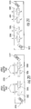
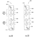
- FIGS 20-23 show a patch panel 1000 that can be used to connect transition devices such as those shown in Figures 16 and 17 to trunk cables.
- the patch panel 1000 includes four adapter apertures 1002, 1004, 1006, 1008, which are arranged in "A" and "B" pairs, with their alignment keyways oriented in the same direction.
- the adapter apertures 1002, 1004, 1006, 1008 are sized to receive trunk cables such as trunk cables 200 and 920 discussed above.
- a transition device such as the transition device 900, would supply trunk end terminals 902, 903 to the patch panel 1000 for interconnection with the trunk cables.
- the panel 1000 also includes orientation indicia 1010 on one corner thereof and orientation indicia 1012 in the opposite corner thereof. As described in detail in U.S. Patent No.
- orientation indicia are themselves oriented such that an "alpha" configuration is indicated when the orientation indicia 1010 is easily read (as in the horizontal orientation of Figure 20 or the vertical orientation of Figure 22 ), and a "beta” orientation is indicated when the orientation indicia 1012 is easily read (as in the horizontal orientation of Figure 21 or the vertical orientation of Figure 23 ).
- the orientation is inverted (e.g., the alpha orientation of Figure 20 versus the beta orientation of Figure 21 )
- the positions of the "A" and "B" pairs are reversed: in the alpha configuration, the B apertures 1002, 1006 are positioned on the left side of each pair, whereas in the beta configuration, the A apertures 1004, 1008 are on the left side of each pair).
- Figure 24 shows a 36-fiber transition device 1100 with three rows of twelve fibers each at the transceiver end terminal 1102.
- the transition device 1100 includes the transceiver end terminal 1102 and three trunk end terminals 1104, 1106, 1108.
- the transceiver end terminal 1102 has port positions that are numbered 1-6, 7-12 and 13-18 on each side of a vertical axis of symmetry A6. Fibers extend from ports 1-4, 7-10 and 13-16 on the left side of the axis A6 to the trunk end terminal 1104, where they feed a single row of ports 1-12.
- Trunk end terminal 1106 receives fibers from ports 5, 6, 11, 12, 17 and 18 from each side of the axis A6 as a single row, wherein each fiber is routed to a port that is the mirror image of the port to which its mirror image fiber is routed. As such, trunk end terminal 1106 meets condition (i).
- the fibers in the trunk end terminals 1104, 1106, 1108 are positioned to produce mirror image order about a central plane that extends through the center of the horizontal arrangement of the trunk end terminals and includes the axis A6.
- two identical transition devices 1100 may be employed in a system with two 36-fiber transceivers and provide proper polarity.
- the transition device 1200 includes a transceiver end terminal 1202 with 36 ports arranged in the same three rows and the same numbering scheme as described above for the transition device 1100 and shown in Figure 24A .
- the fibers are routed from ports 1-12 of the transceiver end terminal 1202 to similarly numbered ports in the trunk end terminals 1204, and to the reverse ordered ports in the trunk end terminal 1208. Fibers are routed from ports 13-18 on each side of the axis A7 into a single row in trunk end terminal 1206.
- the trunk end terminals 1204, 1208 meet condition (ii), and the trunk end terminal 1206 meets condition (i).
- the arrangement of fibers and trunk end terminals in the transition device 1200 produces a mirror image about a plane that extends through the axis A7.
- the system 1150 includes two 36-fiber transceivers 1110, 1112 that are connected with the transition devices and three identical 12-fiber trunk cables 1120, 1120', 1120".
- the trunk end terminal 1104 of transition device 1100 is connected to the trunk end terminal 1108' of the transition device 1100' via the trunk cable 1120
- the trunk end terminal 1106 is connected to the trunk end terminal 1106' via trunk cable 1120'
- the trunk end terminal 1108 is connected to the trunk end terminal 1104' via the trunk cable 1120.
- a signal starting at position 1 on the right side of the upper row of the transceiver 1110 passes through the transceiver end terminal 1102 and into the rightmost fiber of the transition device 1100. From there, the signal passes through the rightmost port of the trunk end terminal 1108 and into the rightmost fiber of the trunk cable 1120. The signals then travels through the rightmost port of the trunk end terminal 1104' and into the rightmost fiber of the transition device 1100'. The signal is then routed through the rightmost port of the upper row of the transceiver end terminal 1102' and into the transceiver 1112, where it is received by receiver R1 at position 1.
- the return path begins at transmitter T1 , from where the signal passes (a) through the leftmost position of the upper row of the transceiver end terminal 1102', (b) along the leftmost fiber of the transition device 1100', (c) through the leftmost port of the trunk end terminal 1108', (d) along the leftmost fiber of the trunk cable 1120", (e) into and through the leftmost port of the trunk end terminal 1104, (f) along the leftmost fiber of the transition device 1100, and (g) into and through the leftmost port of the upper row of the transceiver end terminal 1102, where it is received at the receiver R1. Similar tracings can be performed for the other channels of the system to demonstrate proper connectivity. Thus, it can be seen that the system 1150 maintains proper polarity between the transceivers 1110, 1112 with two identical transition devices 1100, 1100' and three identical trunk cables 1120, 1120', 1120".
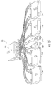
- FIG. 27 and 28 it can be seen that systems of the present invention, and in particular the system 1150 illustrated in Figure 27 , can be inverted to facilitate operations.
- Figures 27 and 28 show the same system in two different perspectives for clarity.
- adapters designated at 1130 and 1130' in Figures 27 and 28
- adapter 1130 can be rotated as a ganged group from keyways-up on one cable end ( i.e., where terminals 1122, 1122', 1122" connect with adapter 1130 ) to keyways-down on the opposite cable end ( i .
- terminals 1124, 1124', 1124" connect with adapter 1130' ). Inverting the keyways so that they face downwardly on one end allows spatial position of signals to be the same on panels at both ends of the cable. To achieve this arrangement and maintain connectivity, the trunk cables 1120, 1120', 1120" are shown with a twist that is imparted by this adapter rotation. Similarly, because the trunk end terminals 1104', 1106', 1108' are oriented with their keyways facing downwardly to attach to the adapter 1130', the fibers of the transition device 1100' are shown with a twist so that the transceiver end terminal 1102' is still oriented in a "key-up" orientation to connect with transceiver 1112. Those skilled in this art will recognize that similar arrangements with others of the systems illustrated and discussed herein may also be employed.
- the device 100 may be modified such that one transceiver end terminal would receive fibers 1, 2, 11 and 12, another would receive fibers 3, 4, 9 and 10, and a third would receive fibers 5-8, as each of these transceiver end terminals would meet condition (b).
- multi-row transceivers with even numbers of rows may employ a modified version of the arrangement of Figure 16 with all of the transmitters in the top half of the rows and all of the receivers in the bottom half of the rows.
Landscapes
- Physics & Mathematics (AREA)
- General Physics & Mathematics (AREA)
- Optics & Photonics (AREA)
- Light Guides In General And Applications Therefor (AREA)
- Optical Communication System (AREA)
Applications Claiming Priority (3)
| Application Number | Priority Date | Filing Date | Title |
|---|---|---|---|
| US12/608,230 US8485737B2 (en) | 2009-10-29 | 2009-10-29 | Optical fiber array connectivity system for multiple transceivers and/or multiple trunk cables |
| EP10757678.7A EP2494395B1 (de) | 2009-10-29 | 2010-09-15 | Glasfaserarraykonnektivitätssystem für mehrere transceiver und/oder mehrere fernkabel |
| PCT/US2010/048873 WO2011053409A1 (en) | 2009-10-29 | 2010-09-15 | Optical fiber array connectivity system for multiple transceivers and/or multiple trunk cables |
Related Parent Applications (1)
| Application Number | Title | Priority Date | Filing Date |
|---|---|---|---|
| EP10757678.7A Division EP2494395B1 (de) | 2009-10-29 | 2010-09-15 | Glasfaserarraykonnektivitätssystem für mehrere transceiver und/oder mehrere fernkabel |
Publications (2)
| Publication Number | Publication Date |
|---|---|
| EP3312650A2 true EP3312650A2 (de) | 2018-04-25 |
| EP3312650A3 EP3312650A3 (de) | 2018-07-25 |
Family
ID=43259737
Family Applications (2)
| Application Number | Title | Priority Date | Filing Date |
|---|---|---|---|
| EP10757678.7A Active EP2494395B1 (de) | 2009-10-29 | 2010-09-15 | Glasfaserarraykonnektivitätssystem für mehrere transceiver und/oder mehrere fernkabel |
| EP17203977.8A Pending EP3312650A3 (de) | 2009-10-29 | 2010-09-15 | Glasfaserarraykonnektivitätssystem für mehrere transceiver und/oder mehrere fernkabel |
Family Applications Before (1)
| Application Number | Title | Priority Date | Filing Date |
|---|---|---|---|
| EP10757678.7A Active EP2494395B1 (de) | 2009-10-29 | 2010-09-15 | Glasfaserarraykonnektivitätssystem für mehrere transceiver und/oder mehrere fernkabel |
Country Status (5)
| Country | Link |
|---|---|
| US (2) | US8485737B2 (de) |
| EP (2) | EP2494395B1 (de) |
| CN (1) | CN102770792B (de) |
| ES (1) | ES2661057T3 (de) |
| WO (1) | WO2011053409A1 (de) |
Families Citing this family (42)
| Publication number | Priority date | Publication date | Assignee | Title |
|---|---|---|---|---|
| US7715679B2 (en) | 2007-05-07 | 2010-05-11 | Adc Telecommunications, Inc. | Fiber optic enclosure with external cable spool |
| US7756379B2 (en) | 2007-08-06 | 2010-07-13 | Adc Telecommunications, Inc. | Fiber optic enclosure with internal cable spool |
| US8737837B2 (en) | 2008-10-14 | 2014-05-27 | Corning Cable Systems Llc | Multi-level distributed fiber optic architectures |
| US9482840B2 (en) | 2009-05-27 | 2016-11-01 | Corning Cable Systems Llc | Port mapping for series connected fiber optic terminals |
| US8251591B2 (en) | 2009-06-17 | 2012-08-28 | Corning Cable Systems | Optical interconnection assemblies and systems for high-speed data-rate optical transport systems |
| US9261654B2 (en) | 2009-10-13 | 2016-02-16 | Leviton Manufacturing Co., Inc. | Fiber optic adapter plates with integrated fiber optic adapters |
| WO2012054091A1 (en) * | 2010-01-19 | 2012-04-26 | Commscope Inc. Of North Carolina | Optical fiber array connectivity system for multiple row trunk cables and terminals |
| US9097873B2 (en) | 2010-04-14 | 2015-08-04 | Corning Cable Systems Llc | Port mapping in fiber optic network devices |
| US8406587B2 (en) * | 2010-05-06 | 2013-03-26 | Commscope, Inc. Of North Carolina | Quad small form factor pluggable (QSFP) adapter module |
| US8961035B2 (en) * | 2010-08-02 | 2015-02-24 | Adc Telecommunications, Inc. | Architecture for a fiber optic network |
| US20120189259A1 (en) * | 2010-12-15 | 2012-07-26 | Leviton Manufacturing Co., Inc. | Pre-terminated fiber devices, systems, and methods |
| US9229172B2 (en) | 2011-09-12 | 2016-01-05 | Commscope Technologies Llc | Bend-limited flexible optical interconnect device for signal distribution |
| US9417418B2 (en) | 2011-09-12 | 2016-08-16 | Commscope Technologies Llc | Flexible lensed optical interconnect device for signal distribution |
| US9097874B2 (en) * | 2012-07-25 | 2015-08-04 | Corning Optical Communications LLC | Polarity configurations for parallel optics data transmission, and related apparatuses, components, systems, and methods |
| US9057863B2 (en) | 2012-07-25 | 2015-06-16 | Corning Cable Systems Llc | Polarity scheme for parallel-optics data transmission |
| ES2792122T3 (es) | 2012-09-28 | 2020-11-10 | Commscope Connectivity Uk Ltd | Casete de fibra óptica |
| US9223094B2 (en) | 2012-10-05 | 2015-12-29 | Tyco Electronics Nederland Bv | Flexible optical circuit, cassettes, and methods |
| US20140140660A1 (en) * | 2012-11-19 | 2014-05-22 | Scott Eaker Buff | Polarity scheme for parallel-optics data transmission |
| TW201437706A (zh) * | 2013-03-18 | 2014-10-01 | Hon Hai Prec Ind Co Ltd | 光纖元件 |
| CN104767561A (zh) * | 2014-01-03 | 2015-07-08 | 上海光维通信技术股份有限公司 | 多通道激光输出装置及mpo光纤连接器的测试装置 |
| US10541754B2 (en) | 2014-05-09 | 2020-01-21 | Sumitomo Electric Lightwave Corp. | Reduced fiber count networks, devices, and related methods |
| US9488795B1 (en) * | 2014-06-27 | 2016-11-08 | Amazon Technologies, Inc. | Optical patch panel |
| US9651755B2 (en) * | 2014-09-30 | 2017-05-16 | Panduit Corp. | Fiber optic interconnect systems and methods |
| EP3018512A1 (de) | 2014-11-05 | 2016-05-11 | Corning Optical Communications LLC | Bidirektionale Datenzentrumsarchitekturen mit einem mantellosen Fernverbindungskabel |
| JP2016126235A (ja) * | 2015-01-07 | 2016-07-11 | ソニー株式会社 | 光コネクタ |
| JP2016126236A (ja) | 2015-01-07 | 2016-07-11 | ソニー株式会社 | 光コネクタ |
| EP3368929A4 (de) * | 2015-10-27 | 2019-06-26 | CommScope, Inc. of North Carolina | Faseroptische spurwechsler zur verwendung mit glasfaserkabeln mit ungenutzten glasfasern sowie entsprechende verfahren |
| US9958620B2 (en) | 2015-12-03 | 2018-05-01 | Sei Optifrontier Co., Ltd. | Optical fiber with connector |
| JP2017156617A (ja) * | 2016-03-03 | 2017-09-07 | 住友電気工業株式会社 | 光接続用部材、光コネクタ、及び、コネクタ付き光ファイバ |
| WO2018046450A1 (en) * | 2016-09-06 | 2018-03-15 | CommScope Connectivity Belgium BVBA | Indexing architecture including an optical fiber cable fan-out arrangement |
| EP3510432A1 (de) | 2016-09-08 | 2019-07-17 | CommScope Connectivity Belgium BVBA | Telekommunikationsverteilungselemente |
| US10267258B2 (en) | 2016-12-05 | 2019-04-23 | Ford Global Technologies, Llc | Method of honing high-porosity cylinder liners |
| EP3404851B1 (de) * | 2017-05-16 | 2020-11-11 | ADVA Optical Networking SE | Optisches verbindungssystem zum verbinden einer ersten und einer zweiten optischen vorrichtung |
| EP3692404A4 (de) | 2017-10-02 | 2021-06-16 | Commscope Technologies LLC | Faseroptische schaltung und herstellungsverfahren |
| WO2020084774A1 (ja) * | 2018-10-26 | 2020-04-30 | 住友電気工業株式会社 | 光コネクタ付きファイバ接続構造、モジュール及びアセンブリ |
| EP4127799B1 (de) | 2020-03-31 | 2025-11-19 | CommScope Technologies LLC | Glasfaserkabelverwaltungssysteme |
| WO2022094286A1 (en) * | 2020-10-30 | 2022-05-05 | Commscope Technologies Llc | Fiber optic connection unit stacking arrangement |
| US20220196939A1 (en) * | 2020-12-17 | 2022-06-23 | Intel Corporation | Molded fiber connector assembly for pluggable optical mcp |
| US11609390B2 (en) * | 2021-01-29 | 2023-03-21 | Mellanox Technologies, Ltd. | Optical splitting adaptor |
| WO2022201474A1 (ja) * | 2021-03-25 | 2022-09-29 | 日本電信電話株式会社 | 多心無反射終端部および光線路試験方法 |
| WO2023137287A1 (en) * | 2022-01-14 | 2023-07-20 | Commscope Technologies Llc | Improved fiber routing and management for a fiber management assembly of a telecommunications closure |
| US12069832B2 (en) * | 2022-11-15 | 2024-08-20 | Corning Research & Development Corporation | Bundled cable assembly |
Citations (2)
| Publication number | Priority date | Publication date | Assignee | Title |
|---|---|---|---|---|
| US7184635B2 (en) | 2004-06-04 | 2007-02-27 | Commscope Solutions Properties, Llc | Optical fiber array connectivity system utilizing angle polished ferrules and aligned-key adapters and cable for same |
| US7416347B2 (en) | 2005-05-31 | 2008-08-26 | Commscope Solutions Properties, Llc | Optical fiber array connectivity system with indicia to facilitate connectivity in four orientations for dual functionality |
Family Cites Families (16)
| Publication number | Priority date | Publication date | Assignee | Title |
|---|---|---|---|---|
| SE510068C2 (sv) | 1997-08-22 | 1999-04-12 | Ericsson Telefon Ab L M | Komponent för korskoppling av optofibrer |
| US6364539B1 (en) * | 1999-03-04 | 2002-04-02 | Avaya Technology Corp. | Stackable multi-fiber ferrules having improved interconnection density |
| US6498882B1 (en) | 2000-11-28 | 2002-12-24 | Lightwave Microsystems Corporation | Assembly and method for reorganizing planar lightwave circuit channels |
| US6556754B2 (en) * | 2001-08-10 | 2003-04-29 | 3M Innovative Properties Company | Three dimensional optical circuit |
| US6850684B2 (en) | 2001-08-10 | 2005-02-01 | 3M Innovative Properties Company | Three dimensional optical circuits |
| US6816642B1 (en) * | 2002-03-01 | 2004-11-09 | Optical Communication Products, Inc. | Apparatus and methods for using fiber optic arrays in optical communication systems |
| JP3840191B2 (ja) | 2003-03-10 | 2006-11-01 | キヤノン株式会社 | 画像形成装置 |
| US6885800B2 (en) * | 2003-05-29 | 2005-04-26 | Molex Incorporated | Method and apparatus of cross-connecting optical fibers with layered substrates forming fiber optic ribbons |
| US7147383B2 (en) * | 2004-12-22 | 2006-12-12 | Corning Cable Systems Llc | Optical polarity modules and systems |
| WO2008134750A2 (en) * | 2007-04-30 | 2008-11-06 | Finisar Corporation | Eye safety and interoperability of active cable devices |
| US7689079B2 (en) * | 2008-01-11 | 2010-03-30 | Corning Cable Systems Llc | Optical fiber interconnection devices and systems using same |
| US8873967B2 (en) * | 2008-10-17 | 2014-10-28 | Corning Cable Systems Llc | Optical interconnection modules for hybrid electrical-optical networks |
| CN102460255A (zh) | 2009-06-17 | 2012-05-16 | 康宁光缆系统有限责任公司 | 用于高速数据率传输系统的光学互连 |
| US8251591B2 (en) * | 2009-06-17 | 2012-08-28 | Corning Cable Systems | Optical interconnection assemblies and systems for high-speed data-rate optical transport systems |
| WO2012054091A1 (en) * | 2010-01-19 | 2012-04-26 | Commscope Inc. Of North Carolina | Optical fiber array connectivity system for multiple row trunk cables and terminals |
| US8406587B2 (en) * | 2010-05-06 | 2013-03-26 | Commscope, Inc. Of North Carolina | Quad small form factor pluggable (QSFP) adapter module |
-
2009
- 2009-10-29 US US12/608,230 patent/US8485737B2/en active Active
-
2010
- 2010-09-15 WO PCT/US2010/048873 patent/WO2011053409A1/en not_active Ceased
- 2010-09-15 EP EP10757678.7A patent/EP2494395B1/de active Active
- 2010-09-15 ES ES10757678.7T patent/ES2661057T3/es active Active
- 2010-09-15 CN CN201080060441.0A patent/CN102770792B/zh active Active
- 2010-09-15 EP EP17203977.8A patent/EP3312650A3/de active Pending
-
2013
- 2013-07-15 US US13/942,212 patent/US9020309B2/en active Active
Patent Citations (2)
| Publication number | Priority date | Publication date | Assignee | Title |
|---|---|---|---|---|
| US7184635B2 (en) | 2004-06-04 | 2007-02-27 | Commscope Solutions Properties, Llc | Optical fiber array connectivity system utilizing angle polished ferrules and aligned-key adapters and cable for same |
| US7416347B2 (en) | 2005-05-31 | 2008-08-26 | Commscope Solutions Properties, Llc | Optical fiber array connectivity system with indicia to facilitate connectivity in four orientations for dual functionality |
Also Published As
| Publication number | Publication date |
|---|---|
| US20110103803A1 (en) | 2011-05-05 |
| US20130343700A1 (en) | 2013-12-26 |
| ES2661057T3 (es) | 2018-03-27 |
| CN102770792B (zh) | 2016-06-08 |
| EP3312650A3 (de) | 2018-07-25 |
| WO2011053409A1 (en) | 2011-05-05 |
| US9020309B2 (en) | 2015-04-28 |
| EP2494395A1 (de) | 2012-09-05 |
| US8485737B2 (en) | 2013-07-16 |
| CN102770792A (zh) | 2012-11-07 |
| EP2494395B1 (de) | 2017-11-29 |
Similar Documents
| Publication | Publication Date | Title |
|---|---|---|
| EP2494395B1 (de) | Glasfaserarraykonnektivitätssystem für mehrere transceiver und/oder mehrere fernkabel | |
| CN102804016B (zh) | 用于多行中继电缆和端子的光纤阵列连接性系统 | |
| US11740424B2 (en) | Structured fiber optic cabling system including an array of ports and orthogonally arranged jumper assemblies | |
| US7416347B2 (en) | Optical fiber array connectivity system with indicia to facilitate connectivity in four orientations for dual functionality | |
| US8406587B2 (en) | Quad small form factor pluggable (QSFP) adapter module | |
| AU2018200618A1 (en) | Polarity scheme for parallel-optics data transmission | |
| US9097874B2 (en) | Polarity configurations for parallel optics data transmission, and related apparatuses, components, systems, and methods | |
| US20210278621A1 (en) | Optical fiber connectivity system including modules and interconnection cables | |
| US9057863B2 (en) | Polarity scheme for parallel-optics data transmission | |
| AU2010260367A1 (en) | Optical interconnections for high-speed data-rate transport systems | |
| US9651755B2 (en) | Fiber optic interconnect systems and methods | |
| WO2006130549A2 (en) | Optical fiber array connectivity system with indicia to facilitate connectivity in four orientations for dual functionality | |
| US20250116827A1 (en) | Connectivity system integrating keying elements | |
| CN114167551A (zh) | 一种用于多光纤的连接器 | |
| AU2015296847A1 (en) | Polarity configurations for parallel optics data transmission, and related apparatuses, components, systems, and methods |
Legal Events
| Date | Code | Title | Description |
|---|---|---|---|
| PUAI | Public reference made under article 153(3) epc to a published international application that has entered the european phase |
Free format text: ORIGINAL CODE: 0009012 |
|
| STAA | Information on the status of an ep patent application or granted ep patent |
Free format text: STATUS: THE APPLICATION HAS BEEN PUBLISHED |
|
| AC | Divisional application: reference to earlier application |
Ref document number: 2494395 Country of ref document: EP Kind code of ref document: P |
|
| AK | Designated contracting states |
Kind code of ref document: A2 Designated state(s): AL AT BE BG CH CY CZ DE DK EE ES FI FR GB GR HR HU IE IS IT LI LT LU LV MC MK MT NL NO PL PT RO SE SI SK SM TR |
|
| PUAL | Search report despatched |
Free format text: ORIGINAL CODE: 0009013 |
|
| AK | Designated contracting states |
Kind code of ref document: A3 Designated state(s): AL AT BE BG CH CY CZ DE DK EE ES FI FR GB GR HR HU IE IS IT LI LT LU LV MC MK MT NL NO PL PT RO SE SI SK SM TR |
|
| RIC1 | Information provided on ipc code assigned before grant |
Ipc: G02B 6/44 20060101AFI20180621BHEP |
|
| STAA | Information on the status of an ep patent application or granted ep patent |
Free format text: STATUS: REQUEST FOR EXAMINATION WAS MADE |
|
| 17P | Request for examination filed |
Effective date: 20190124 |
|
| RBV | Designated contracting states (corrected) |
Designated state(s): AL AT BE BG CH CY CZ DE DK EE ES FI FR GB GR HR HU IE IS IT LI LT LU LV MC MK MT NL NO PL PT RO SE SI SK SM TR |
|
| STAA | Information on the status of an ep patent application or granted ep patent |
Free format text: STATUS: EXAMINATION IS IN PROGRESS |
|
| 17Q | First examination report despatched |
Effective date: 20220218 |
|
| RAP3 | Party data changed (applicant data changed or rights of an application transferred) |
Owner name: COMMSCOPE NORTH CAROLINA, LLC |